lf conductivity measuring probe - pfaudler messtechnik · lf conductivity measuring probe operating...
TRANSCRIPT

LF Conductivity Measuring Probe
Operating InstructionsOperating Instructions
376-4 e
Contents
1 General1.1 Introduction1.2 Application range2 Safety2.1 Warnings and symbols3 Transport and storage4 Application5 Measuring principle6 Assembly7 Construction8 Technical data8.1 Explosion protection9 Calibration10 Startup10.1 Electrical connection11 Spare parts12 Related documents13 Glass Testing14 Avoiding damages to
peripheral devices
Annex 1EC-Type-Examination-Certificate
Annex 2Declaration of conformity

LF Conductivity Measuring Probe
1 General
1.1 IntroductionThe probe may only be installed, started up and serviced by authorized personnel with special skills in measuring technology and in strict compliance with the present instructions as well as the valid provi-sions. Non-compliance with these provi-sions – no matter whether by intention or by negligence – shall release the manu-facturer from all responsibility and relia-bility.
The present operating instructions are designed to familiarize users with the equipment of the probe and its use. The operating instructions should be availa-ble to the operating and maintenance personnel and should be studied before performing any installation and/or main-tenance work.
By knowing these operating instructions, you can avoid damages to the measuring equipment and ensure trouble-free opera-tion.
The representations and data given in these Operating Instructions are subject to modification and further improvement. The latest edition hereof will always supersede all previous ones.
1.2 Application rangeLF probes are used to measure the con-ductivity of changes in conductivity. Never operate this measuring device outside its permissible operating conditions.
2 SafetyThe safety instructions refer exclusively to the scope of delivery. Please also note the valid safety regulations concerning electrical installations and facilities.
2.1 Warnings and symbolsIn the operating instructions, the danger symbol is used to draw your attention to especially important information.
m Compliance with these man-datory instructions helps to avoid personal injury and damage to property.
m Please note the following instructions: Do not practice any working methods which may endan-ger safety!
3 Transport and storageThe probe should only be transported and stored in its closed original packag-ing.
In order to guarantee an as-new condi-tion of the probe, maintain the following storage conditions:■■ dry and dust-free,■■ steady temperature and ventilation
When used probes are sent to the manu-facturer or third parties for repair or other purposes, all parts must be cleaned and decontaminated. Appropriate safety instructions for further handling must be attached to the outside of the packaging.
The probes do not need any preserva-tives, they are resistant to normal envi-ronmental influences.
4 ApplicationThe fully glasslined LF measuring probe is used to measure the electrolytic con-ductivity and can be installed directly inside reactors or pipes. For the resistance of the glass lining used, please refer to our publication no. 614. The LF probe is preferably used for measurement in con-centrated acids at high temperatures and high pressures up to 40 bar (special option up to 100 bar).
2 © Pfaudler GmbH
Figure 1 LF measuring probes

LF Conductivity Measuring Probe
5 Measuring principleThe 4-electrode method is used. A con-stant AC current flows through the external electrodes. The measuring-circuit voltage is picked up in the form of a resistancede-pendent voltage drop across the internal electrodes without current load. The volt-age value is then supplied to a transmitter with a high-resistance input. This measur-ing method is largely insensitive to con-tamination of the electrodes. Polarization errors are impossible because polarization only occurs at the current electrodes.
A built-in Pt 100 resistance thermometercompensates for the temperature de-pendence of the conductivity.
By combining steel, glass and rhodium (for the electrodes) as materials for the probe, the LF probe was given a number of outstanding characteristics:■■ high resistance to corrosion■■ large temperature application rangebetween –25 . . . +200 °C
■■ resistance to pressure: –1 . . . +40 bar(option 100 bar)
■■ resistance to thermal shock
3
Due to these properties, it is even suita-ble for extreme applications.
6 AssemblyWhen measuring in pipes made of plastic materials or steel with an insulating lining, the use of conductive gaskets offers advantages. These gaskets are connect-ed to the equipotential bonding system of the probe.DN50 part number 029 651-DN80 part number 029 652-
When installing the probe in steel pipes, only normal, non-conductive gaskets may be used due to the possible forma-tion of electrolytic element couples between components.DN50 part number 027 728-DN80 part number 027 730-
For the tightening torques of the split flange connection, please refer to Serv-ice Instructions 318. After the first tem-perature cycle (but by no means later than after 24 hours) the screws must be retightened with the prescribed torque.
© Pfaudler GmbH
le cas échéant, ligne de compensation du potentie
l
LF
Figure 2 LF measuring probe in pipes
Figure 3 Structure of the LF measuring probes
equipotential bonding conductor, if necessary
U≈
Process conductometermS/cm – % by weight
mA
Ri = ∞
≈
i
lk ≈
Glass
Rhodiumelectrodes
Pt 100
Metal body
U≈

LF Conductivity Measuring Probe
7 ConstructionThe four metal electrodes with a diame-ter of 2 mm have been fused into the glass layer of a measuring probe carrier so as to ensure insulation between them. Measuring probe carriers may include baffles, thermometer wells or spacing rings.
The supply conductors for the electrodes are also fused into glass and lead to a terminal box at the flange of the probe carrier. The Pt 100 has been integrated into the steel body of the probe carrier.
Baffles and thermometer wells are avail-able in any desired size, spacing rings may be manufactured from DN 50.
9 CalibrationThe glasslined conductivity measuring probe is an open measuring cell, there-fore, it has to be calibrated in the reac-tor/in the pipe in order to allow the stray field to be fully generated. For this rea-son, a transmitter is to be used which can be calibrated for the conductivity data of the product and which automati-cally calculates the cell constant after calibration.
For calibration, the measuring probe is installed inside the reactor or the pipe and filled with product. Measure the con-ductivity of a product sample using an external conductivity meter. Then enter the measured conductivity manually into the transmitter. Please note that the product temperature must be identical to the sample temperature.
4 © Pfaudler GmbH
8 Technical data
Conductivity range: 1 to 2 000 mS/cm
Temperature range: depends on the temperature compensation of the transmitter used glass limits between –25 and 200 °C
Pressure: 40 bar as a standard; up to 100 bar in special design
Electrode material: Rhodium 2 mm in diameter
Cell constant: approx. 0.2 cm–1, depending on design
Glass lining: Glass WWG 9115
1000
100
10
1
0,1
g/l ➜■
0,1 1 10,05 100,6
0,01 0,1 1 10 % by weight
➜■mS/cm
Figure 4 Concentration table H2SO4 20 °C
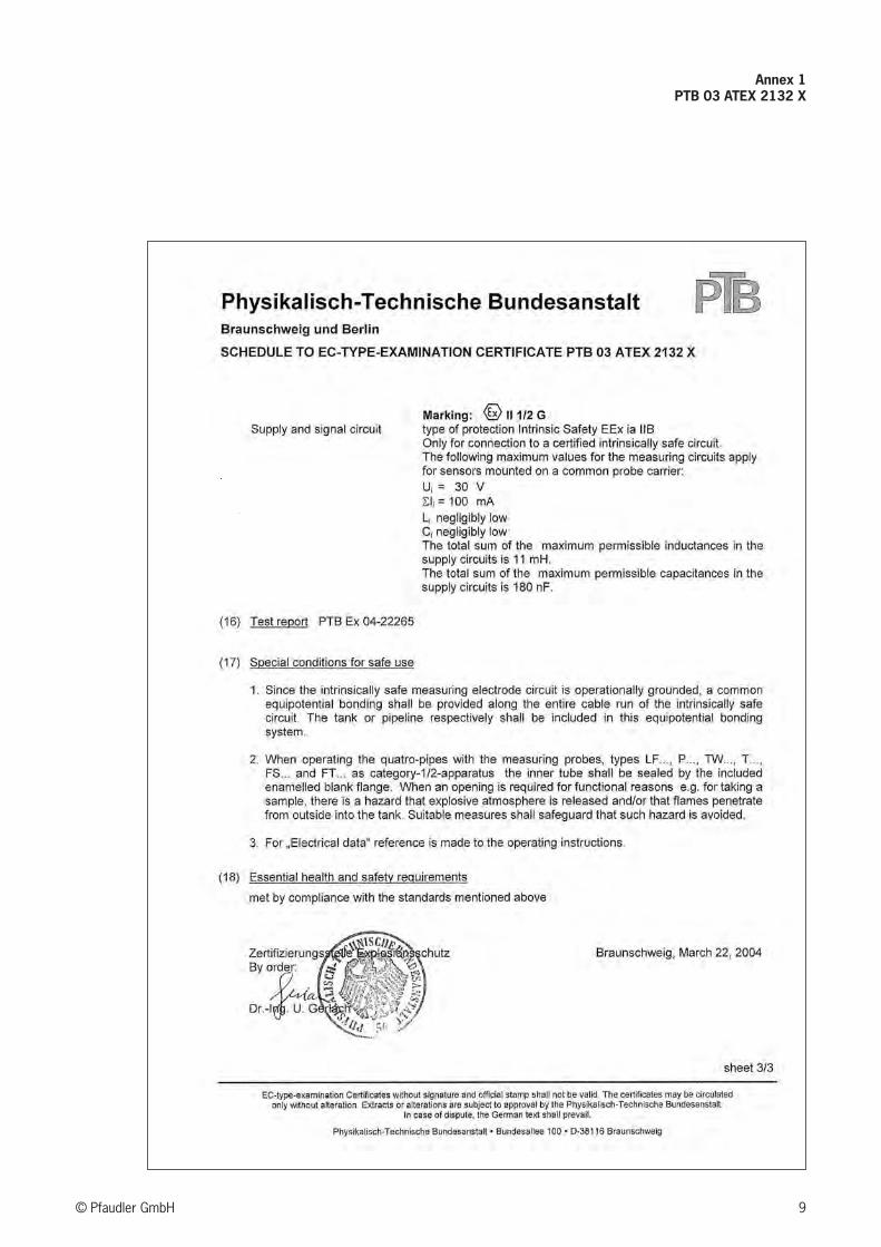
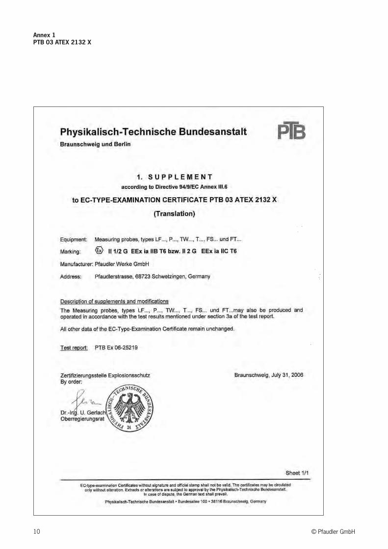
8.1 Explosion protectionWhen using the measuring probe type LF (type of protection: intrinsic safety Ex ia IIC) in potentially explosive areas of zone 0, it is approved for connection to intrinsi-cally safe circuits category “ia” with elec-trical isolation and the maximum electri-cal values specified in the certificate of conformity PTB No. Ex-88.B.2127X.

LF Conductivity Measuring Probe
10 StartupConnect the measuring probe and the transmitter according to the applicable wiring diagram. Startup comprises the parameterization and calibration of the transmitter.
The wiring diagrams of suitable conduc-tivity meters are available on request.■■ During parameterization, enter a cellconstant of approx. 0.2 cm–1.
■■ Measuring range of 1 mS and higher,for a conductivity ≤ 1 mS transmittermessages may be output (sensor notstable), depending on the design andplace of installation of the transmitter.
m Caution!■■ When the probe has been installedin another measuring location, it has to be re-calibrated.
■■ Once a cell constant has been determined, it can always be used if the probe and place of installa-tion are identical.
11.1 Electrical connection
5© Pfaudler GmbH
Figure 5 Connection cable assignment
12
34
56
89
# Conductor color Assignment
1 white voltage electrode coaxial cable
2 brown voltage electrode coaxial cable
3 brown current electrode + Pt 100
4 green Pt 100
5 blue current electrode
6 black Pt 100
Cable shield (total shield on connector to frame)
8 violet coaxial cable shield 1 (insulated at connector)
9 orange coaxial cable shield 2 (insulated at connector)
Figure 6 Terminal box
1
2
5
6
3
4

LF Conductivity Measuring Probe
6 © Pfaudler GmbH
14 Avoiding damages to peripheral devices
■■ When performing a spark test, pleasenote the following information; other-wise, the components and/or theelectronic transmitter may get dam-aged.
■■ The measuring transducers for tem-perature, glass monitoring, capaci-tive sensors and other electronic/electric components that have beenattached to the valve or the bafflemust be disconnected prior to thespark test.
■■ Suitable equipment must be em-ployed for the test (impulse voltage).We recommend using the GlaSparker®,our high-voltage tester
■■ For glass lined measuring probes, themax. test voltage must not exceed7 kV.
■■ The contact window around the meas-uring probe site (e.g. P) must not betested.
In general, however, we recommend call-ing our technical service for performing the test.
female connector
female connector
male connector
protective cap
mains
current output
screwed connection
conductivity processor
(conductive)
Figure 7 Wiring diagram
Measuring Points
Figure 8 Contacs
400 mm
1200
mm
11 Spare parts
Designation Part no.
O-ring made of Viton for protectivecap, 25 x 1.5 mm 024 336 D
Connection cable, blue, 2 m with connector 254 634 2
Connection cable, blue, 5 m with connector 254 634 5
Connection cable, blue, 10 m with connector 254 634 0
12 Related documentsService Instruction 318 Tightening Torques
13 Glass testingDuring a spark test, inflammable sparks may occur at the pores in the form of an electric arc. Therefore, spark testing may only be carried out outside of poten-tially explosive atmospheres.

Annex 1PTB 03 ATEX 2132 X
7© Pfaudler GmbH

Annex 1PTB 03 ATEX 2132 X
8 © Pfaudler GmbH
Annex 1PTB 03 ATEX 2132 X
9© Pfaudler GmbH
10 © Pfaudler GmbH
Annex 1PTB 03 ATEX 2132 X

11© Pfaudler GmbH
Annex 1PTB 03 ATEX 2132 X

12 © Pfaudler GmbH
Annex 1PTB 03 ATEX 2132 X

13© Pfaudler GmbH
Annex 1PTB 03 ATEX 2132 X

14 © Pfaudler GmbH
Annex 2Declaration of conformity

Notes
15© Pfaudler GmbH
The information provided in this documentation corresponds
to the state of the art at the time of printing. It is published
in good faith. However, we will accept no warranty claims
based on the information provided in this documentation. We
reserve the right to include improvements, amendments and
new findings in this documentation without prior notice. The
actual design of products may deviate from the information
contained in the calatoge if technical alterations and product
improvements so require. The proposal made by Pfaudler for
a concrete application will be binding in such cases.
The present documentation is made available free of charge
to our customers and other interested parties. The right to
print or copy this documentation, or any parts there of, or to
convert the same into electronic form shall be subject to our
written permission.
All rights reserved by us.
Pfaudler Werke GmbH
P.O. Box 1780 D-68721 Schwetzingen
Pfaudlerstraße D-68723 Schwetzingen
Phone +49 6202 85-233
Telefax +49 6202 85-273
E-mail [email protected]
www.pfaudler-instrumentation.com