led runway guard light l-804 mode 1 and mode 2 user …
TRANSCRIPT
MAN-FX01 Rev 1.2 3/18/2020
LED Runway Guard Light
L-804 Mode 1 and Mode 2 User Manual
Revision 1.2
In accordance with:
FAA
Advisory Circular AC-150/5345-46
And
Engineering Brief 67
Manufactured by: Airport Lighting Company 108 Fairgrounds Drive Manlius, New York 13104 (315) 682-6460 Email: [email protected]
Website: www.airportlightingcompany.com
MAN-FX01 Rev 1.2 3/18/2020
Warranty – LED Light Source Products FAA EB67D
Products manufactured by Airport Lighting Company (ALC) which use LEDs as a light source are warranted against
mechanical and physical defects in design or manufacture for a period of 2 years from date of installation per the
applicable FAA Advisory Circular and against electrical defects in design or manufacture of the LED or LED specific
circuitry for a period of 4 years per FAA EB67D. ALC will correct such defects by repair or replacement, at its option,
provided the products have been properly handled and stored prior to installation, properly installed and operated
after installation, and provided further that the Buyer has notified ALC in writing within the warranty period and
within a reasonable time after notice of such defects. Refer to handling, storage, installation and operational
instructions for proper procedural guidance that must be followed to maintain warranty provisions.
This warranty is in effect for the specified term as long as the equipment, in ALC's judgment, has not been altered in
such a way as to affect the equipment adversely, subject to accident, negligence, improper storage, and has been
operated and maintained in accordance with accepted FAA guidelines as described in AC 150/5340-26 and ALC’s
published operational guidelines.
ALC reserves the right to examine products about which a claim has been made. Equipment must be presented in
the same condition as when the defect was discovered. ALC also reserves the right to require the return of
equipment to establish any claim.
Disclaimer: ALC's obligation under this warranty is limited to repair or replacement of defective equipment sold by
ALC at no cost to Buyer. This does not include any other costs such as the cost of removal, shipping, or installation
of the defective part or repaired or replaced product, including labor or any consequential damages of any kind.
Warranty services provided under this agreement do not assure uninterrupted operations of LED illuminated
equipment. ALC shall not be liable for any indirect or consequential damages.
ALC's liability under no circumstances will exceed its sales price of the products claimed to be defective. All
transportation costs under this warranty are the responsibility of the purchaser. Replacement parts and/or
equipment provided under this warranty are covered under the same terms until the expiration of the original
warranty period that began upon the first installation of the equipment.
This is ALC's sole and exclusive warranty with respect to the equipment sold to the Buyer. There
are no express or implied warranties of fitness for any particular purpose or any implied warranties other than
those made expressly herein.
ALC shall not be liable to the purchaser of this product or third parties for indirect or consequential damages, or for damages arising from the use of any options or parts other than those designated by ALC as approved products. Damage caused by lightning, flood and other natural or manmade causes are outside the scope of this warranty.
MAN-FX01 Rev 1.2 3/18/2020
Table of Contents 1.1 General Information ...................................................................................................................................... 3
1.2 Mode 1 (Series - Powered) ............................................................................................................................ 4
1.3 Mode 2 (Parallel - Powered) .......................................................................................................................... 4
1.4 Additional Features ....................................................................................................................................... 5
1.5 Power Consumption Mode 1 (Series - Powered) .......................................................................................... 5
1.6 Power Consumption Mode 2 (Parallel - Powered) ........................................................................................ 5
2.1 FAA References and Siting Requirements ..................................................................................................... 5
3.1 Installation ..................................................................................................................................................... 8
3.2 System Test, Mode 1 (Series Powered) ....................................................................................................... 11
3.3 System Test, Mode 2 (Parallel Powered) .................................................................................................... 11
3.4 Maintenance ................................................................................................................................................ 12
3.5 Replacing a Broken Frangible Column ......................................................................................................... 12
4.1 Runway Guard Light Operational Outline ................................................................................................... 13
4.2 Mode 1 (Series-Powered) RGL Power Supply .............................................................................................. 13
4.3 Mode 2 (Parallel-Powered) RGL Power Supply ........................................................................................... 13
4.4 RGL Control Board ....................................................................................................................................... 13
4.5 Fault Detection, Light Engine Failure ........................................................................................................... 14
4.6 Fault Detection, Flash Failure ...................................................................................................................... 14
4.7 Guard Light Controller Trouble Shooting .................................................................................................... 15
List of Figures Figure 1: FAA Guard Light Field Placement (from AC 150/5340-30) ....................................................7 Figure 2: Installing Frangible Column ...................................................................................................8 Figure 3: Anti-rotation clamp, nut and baseplate ................................................................................8 Figure 4: Plug Retainer..........................................................................................................................9 Figure 5: Initial Placement.....................................................................................................................9
Figure 6: Tether...................................................................................................................................10
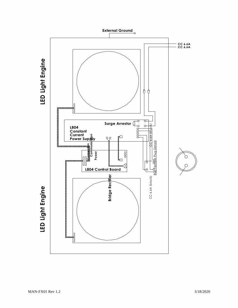
Figure 7: Vertical Adjustment..............................................................................................................11 Figure 8: L-804 Runway Guard Light Control Board............................................................................15 Figure 9: Wiring diagram for a current style L-804 Runway Guard Light shown without
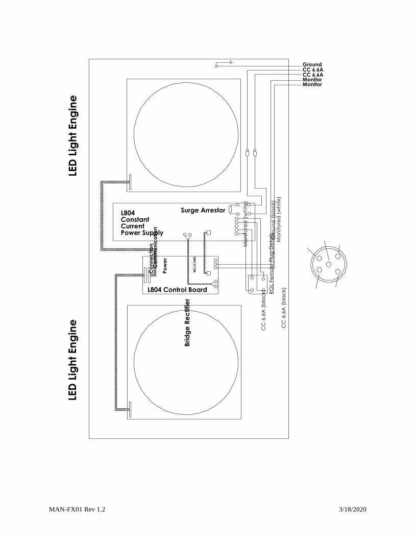
monitoring..........................................................................................................................................16 Figure 10: Wiring diagram for a current style L-804 Runway Guard Light shown with
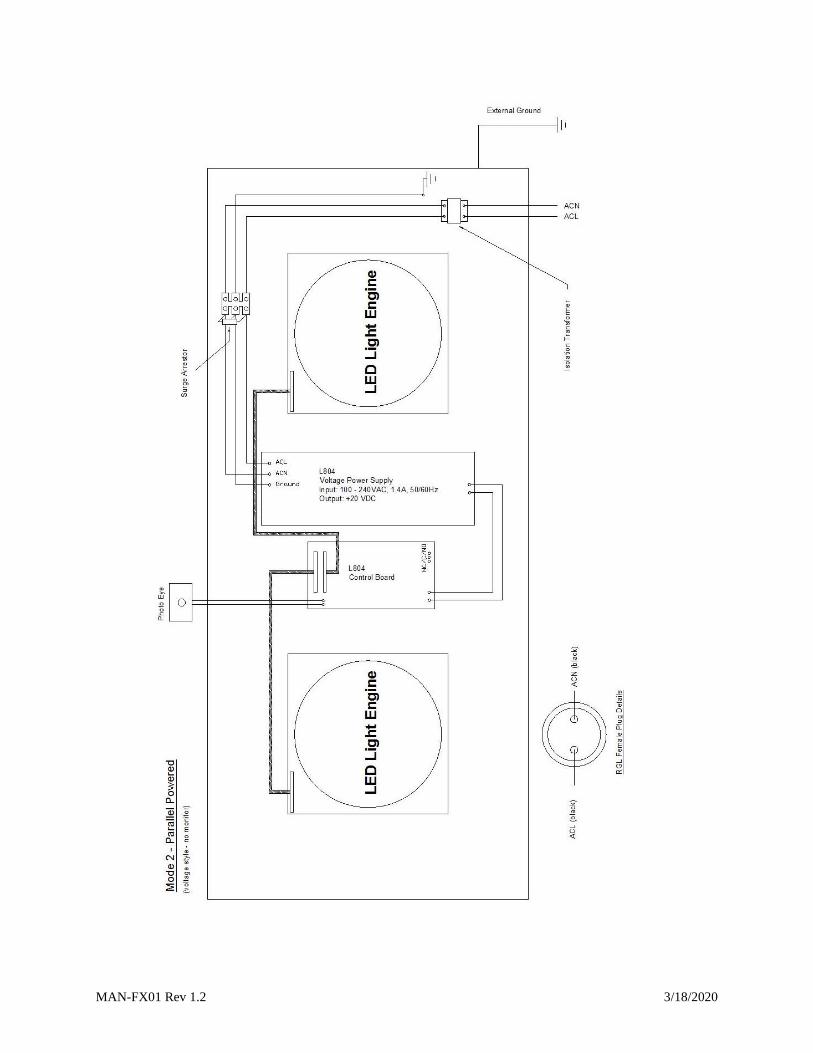
monitoring..........................................................................................................................................16 Figure 11: Wiring diagram for a voltage style L-804 Runway Guard Light shown without
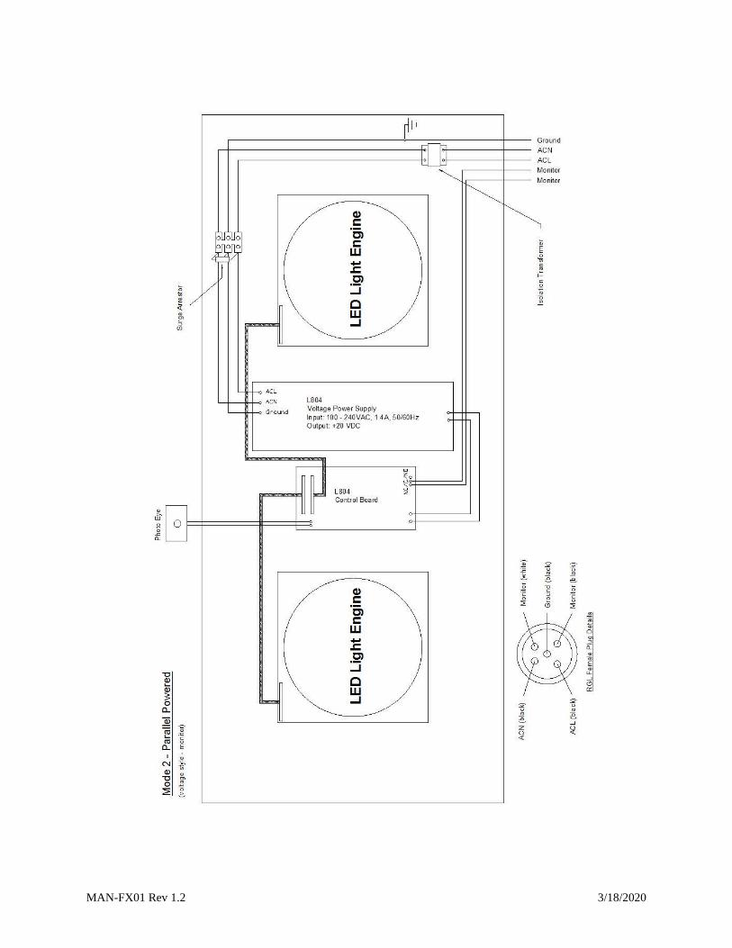
monitoring..........................................................................................................................................16 Figure 12: Wiring diagram for a voltage style L-804 Runway Guard Light shown with monitoring ............................................................................................................................................................16
List of Tables Table 1: Recommended Spare Parts …………………………………………………………………………………….……….16 Table 2: Trouble Shooting …………………………………………………………………………….……………………………….17
1.1 General Information
MAN-FX01 Rev 1.2 3/18/2020
The Airport Lighting Company LED Runway Guard Light (LED RGL) is a FAA
certified L-804. The L-804 LED RGL from Airport Lighting Company comes in four
configurations; Mode 1 (Series-Powered), Mode 2 (Parallel-Powered), in either a
monitored or unmonitored configuration. The L-804 LED RGL comes
preassembled from the factory. The Airport Lighting Company LED RGL comes
with a 12” L-867 base plate with an anti-rotation tab and clamp designed to
prevent the unit from rotating when exposed to jet blasts. This all aluminum
design from the frangible column to the LED enclosure prevents corrosion. All
internal electrical connections are completed at the factory. All that is required
from the contractor is to connect the fixture into the correct electrical supply, bolt
the unit to the light base, and make the correct vertical and horizontal angle adjustments.
1.2 Mode 1 (Series - Powered)
The L804 Mode 1 unit runs from constant current airfield electrical system using a
65W, 6.6A isolation transformer. The L-804 Mode 1 monitored units use a 5 pin
plug that includes a ground pin. The monitored units are configured to have a
normally-closed circuit connection when operating properly. Alternatively the
unit can be configured as a normally-open circuit (troubleshooting 1.1).
Unmonitored units use a 2 pin plug. Also supplied with an unmonitored system
are a #6 wire crimp and a toothed washer. The contractor is expected to supply
external ground wire and ground connection on unmonitored systems.
1.3 Mode 2 (Parallel - Powered)
The L-804 Mode 2 unit operates on 100-240 VAC at 50-60Hertz. The L-804 Mode
2 uses a photodiode to discriminate night from day, and switches the light
intensity accordingly. Monitored units use a 5 pin plug that includes a ground pin.
The monitored units are configured to have a normally-closed circuit connection
when operating properly. Alternatively, the unit can be configured as a
normallyopen circuit (troubleshooting 1.1). Unmonitored units use a 2 pin plug.
Also supplied with the unmonitored system are a #6 wire crimp and a toothed
washer.
MAN-FX01 Rev 1.2 3/18/2020
The contractor is expected to supply external ground wire and ground connection
on unmonitored systems.
1.4 Additional Features
This unit is designed to meet FAA light specifications for 50,000 hours of
operation. Internal temperature monitoring automatically adjusts the LED
intensity to maintain a steady light output across the operating temperature
range. The unit records faults in internal memory so that Airport Lighting
Company can review the performance of any unit that is returned to them.
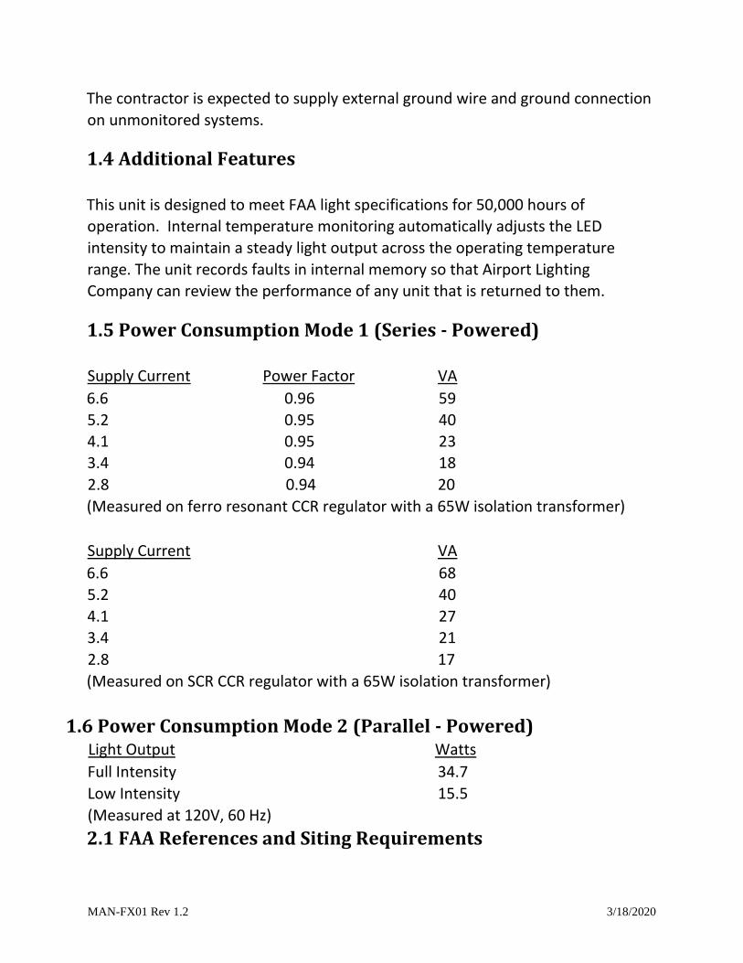
1.5 Power Consumption Mode 1 (Series - Powered)
Supply Current Power Factor VA
6.6 0.96 59
5.2 0.95 40
4.1 0.95 23
3.4 0.94 18
2.8 0.94 20
(Measured on ferro resonant CCR regulator with a 65W isolation transformer)
Supply Current VA
6.6 68
5.2 40
4.1 27
3.4 21
2.8 17
(Measured on SCR CCR regulator with a 65W isolation transformer)
1.6 Power Consumption Mode 2 (Parallel - Powered) Light Output Watts
Full Intensity 34.7
Low Intensity 15.5
(Measured at 120V, 60 Hz)
2.1 FAA References and Siting Requirements
MAN-FX01 Rev 1.2 3/18/2020
Note: When referencing FAA advisory circulars and engineering briefs, Airport Lighting
Company will quote directly from the advisory circular or engineering brief. All FAA references
will be highlighted.
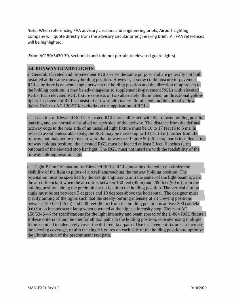
(From AC150/5430-30, sections b and c do not pertain to elevated guard lights) 4.4. RUNWAY GUARD LIGHTS. a. General. Elevated and in-pavement RGLs serve the same purpose and are generally not both
installed at the same runway holding position. However, if snow could obscure in-pavement
RGLs, or there is an acute angle between the holding position and the direction of approach to
the holding position, it may be advantageous to supplement in-pavement RGLs with elevated
RGLs. Each elevated RGL fixture consists of two alternately illuminated, unidirectional yellow
lights. In-pavement RGLs consist of a row of alternately illuminated, unidirectional yellow
lights. Refer to AC 120-57 for criteria on the application of RGLs.
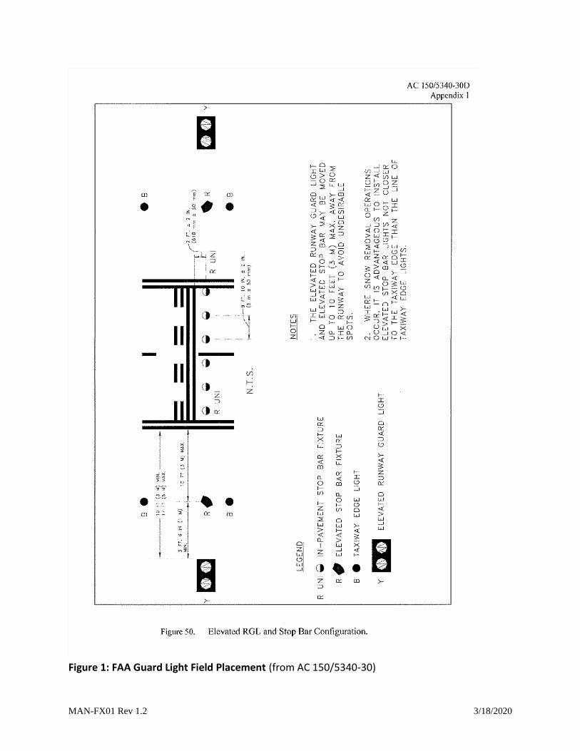
d. Location of Elevated RGLs. Elevated RGLs are collocated with the runway holding position
marking and are normally installed on each side of the taxiway. The distance from the defined
taxiway edge to the near side of an installed light fixture must be 10 to 17 feet (3 to 5 m). In
order to avoid undesirable spots, the RGL may be moved up to 10 feet (3 m) farther from the
runway, but may not be moved toward the runway (see Figure 50). If a stop bar is installed at the
runway holding position, the elevated RGL must be located at least 3 feet, 6 inches (1 m)
outboard of the elevated stop bar light. The RGL must not interfere with the readability of the
runway holding position sign. e. Light Beam Orientation for Elevated RGLs. RGLs must be oriented to maximize the
visibility of the light to pilots of aircraft approaching the runway holding position. The
orientation must be specified by the design engineer to aim the center of the light beam toward
the aircraft cockpit when the aircraft is between 150 feet (45 m) and 200 feet (60 m) from the
holding position, along the predominant taxi path to the holding position. The vertical aiming
angle must be set between 5 degrees and 10 degrees above the horizontal. The designer must
specify aiming of the lights such that the steady-burning intensity at all viewing positions
between 150 feet (45 m) and 200 feet (60 m) from the holding position is at least 300 candela
(cd) for an incandescent lamp when operated at the highest intensity step. (Refer to AC
150/5345-46 for specifications for the light intensity and beam spread of the L-804 RGL fixture.)
If these criteria cannot be met for all taxi paths to the holding position, consider using multiple
fixtures aimed to adequately cover the different taxi paths. Use in-pavement fixtures to increase
the viewing coverage, or aim the single fixtures on each side of the holding position to optimize
the illumination of the predominant taxi path.
MAN-FX01 Rev 1.2 3/18/2020
Figure 1: FAA Guard Light Field Placement (from AC 150/5340-30)
MAN-FX01 Rev 1.2 3/18/2020
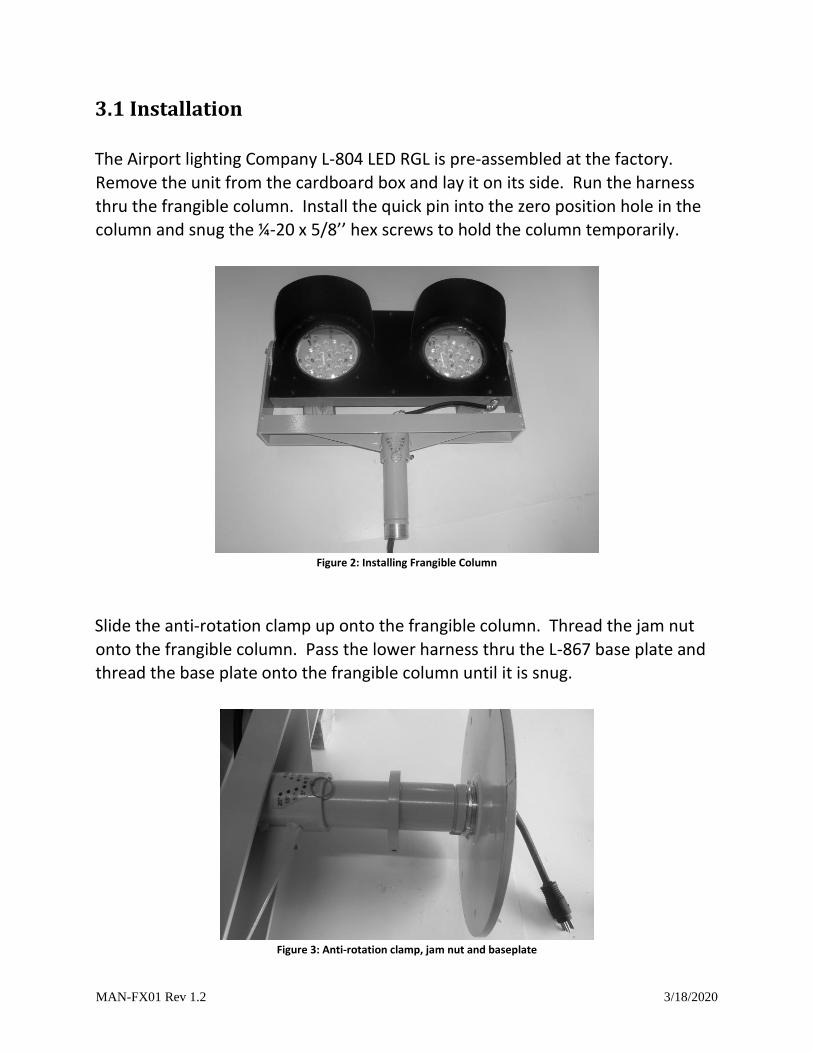
3.1 Installation
The Airport lighting Company L-804 LED RGL is pre-assembled at the factory.
Remove the unit from the cardboard box and lay it on its side. Run the harness
thru the frangible column. Install the quick pin into the zero position hole in the
column and snug the ¼-20 x 5/8’’ hex screws to hold the column temporarily.
Figure 2: Installing Frangible Column
Slide the anti-rotation clamp up onto the frangible column. Thread the jam nut
onto the frangible column. Pass the lower harness thru the L-867 base plate and
thread the base plate onto the frangible column until it is snug.
Figure 3: Anti-rotation clamp, jam nut and baseplate
MAN-FX01 Rev 1.2 3/18/2020
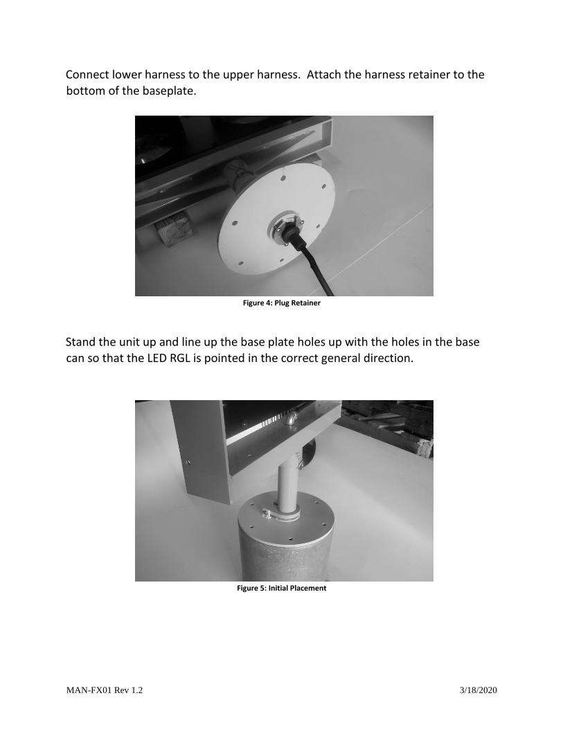
Connect lower harness to the upper harness. Attach the harness retainer to the
bottom of the baseplate.
Figure 4: Plug Retainer
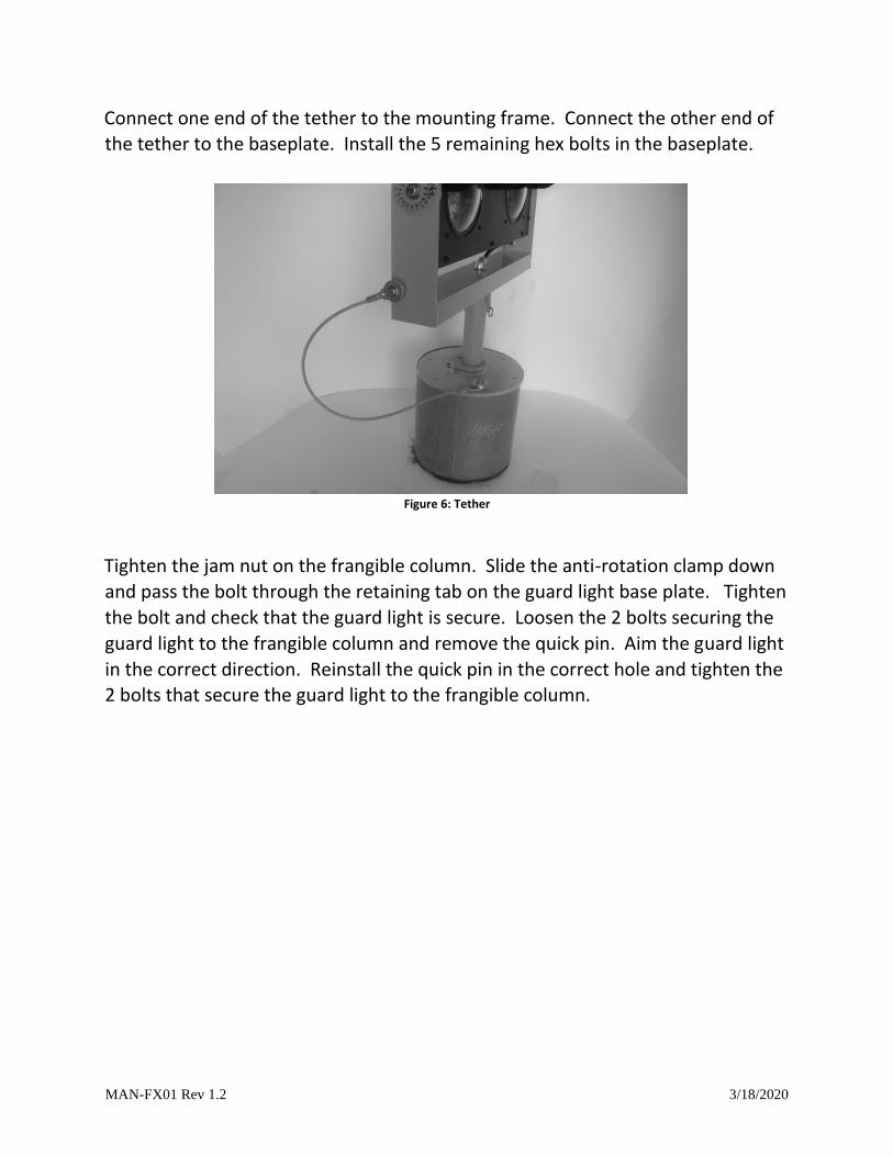
Stand the unit up and line up the base plate holes up with the holes in the base can so that the LED RGL is pointed in the correct general direction.
Figure 5: Initial Placement
MAN-FX01 Rev 1.2 3/18/2020
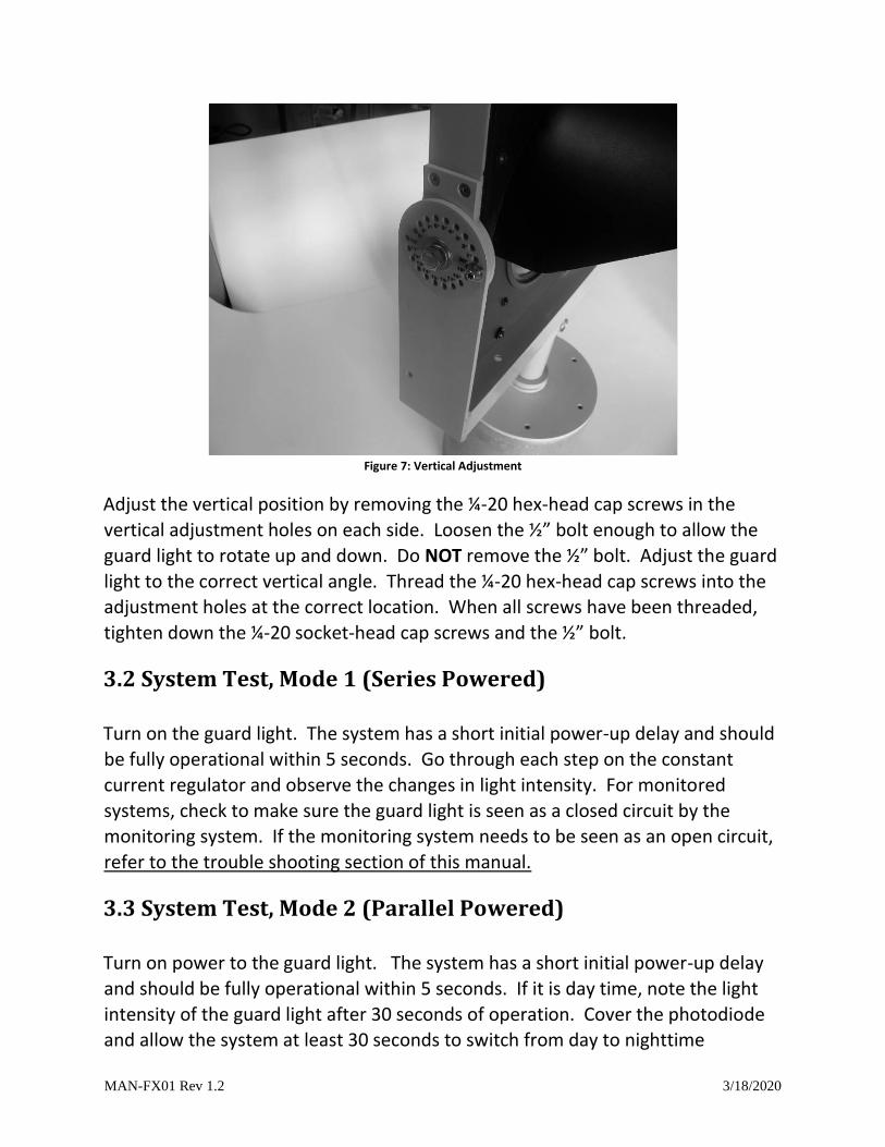
Connect one end of the tether to the mounting frame. Connect the other end of
the tether to the baseplate. Install the 5 remaining hex bolts in the baseplate.
Figure 6: Tether
Tighten the jam nut on the frangible column. Slide the anti-rotation clamp down
and pass the bolt through the retaining tab on the guard light base plate. Tighten
the bolt and check that the guard light is secure. Loosen the 2 bolts securing the
guard light to the frangible column and remove the quick pin. Aim the guard light
in the correct direction. Reinstall the quick pin in the correct hole and tighten the 2 bolts that secure the guard light to the frangible column.
MAN-FX01 Rev 1.2 3/18/2020
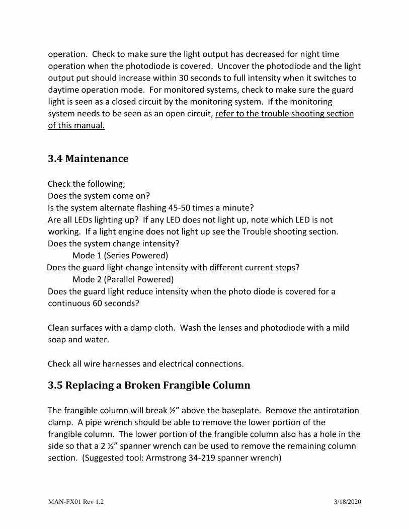
Adjust the vertical position by removing the ¼-20 hex-head cap screws in the
vertical adjustment holes on each side. Loosen the ½” bolt enough to allow the
guard light to rotate up and down. Do NOT remove the ½” bolt. Adjust the guard
light to the correct vertical angle. Thread the ¼-20 hex-head cap screws into the
adjustment holes at the correct location. When all screws have been threaded,
tighten down the ¼-20 socket-head cap screws and the ½” bolt.
3.2 System Test, Mode 1 (Series Powered)
Turn on the guard light. The system has a short initial power-up delay and should
be fully operational within 5 seconds. Go through each step on the constant
current regulator and observe the changes in light intensity. For monitored
systems, check to make sure the guard light is seen as a closed circuit by the
monitoring system. If the monitoring system needs to be seen as an open circuit,
refer to the trouble shooting section of this manual.
3.3 System Test, Mode 2 (Parallel Powered)
Turn on power to the guard light. The system has a short initial power-up delay
and should be fully operational within 5 seconds. If it is day time, note the light
intensity of the guard light after 30 seconds of operation. Cover the photodiode
and allow the system at least 30 seconds to switch from day to nighttime
Figure 7 : Vertical Adjustment
MAN-FX01 Rev 1.2 3/18/2020
operation. Check to make sure the light output has decreased for night time
operation when the photodiode is covered. Uncover the photodiode and the light
output put should increase within 30 seconds to full intensity when it switches to
daytime operation mode. For monitored systems, check to make sure the guard
light is seen as a closed circuit by the monitoring system. If the monitoring
system needs to be seen as an open circuit, refer to the trouble shooting section
of this manual.
3.4 Maintenance
Check the following;
Does the system come on?
Is the system alternate flashing 45-50 times a minute?
Are all LEDs lighting up? If any LED does not light up, note which LED is not working. If a light engine does not light up see the Trouble shooting section.
Does the system change intensity?
Mode 1 (Series Powered)
Does the guard light change intensity with different current steps?
Mode 2 (Parallel Powered)
Does the guard light reduce intensity when the photo diode is covered for a
continuous 60 seconds?
Clean surfaces with a damp cloth. Wash the lenses and photodiode with a mild
soap and water.
Check all wire harnesses and electrical connections.
3.5 Replacing a Broken Frangible Column
The frangible column will break ½” above the baseplate. Remove the antirotation
clamp. A pipe wrench should be able to remove the lower portion of the
frangible column. The lower portion of the frangible column also has a hole in the
side so that a 2 ½” spanner wrench can be used to remove the remaining column
section. (Suggested tool: Armstrong 34-219 spanner wrench)
MAN-FX01 Rev 1.2 3/18/2020
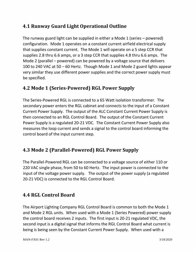
4.1 Runway Guard Light Operational Outline
The runway guard light can be supplied in either a Mode 1 (series – powered)
configuration. Mode 1 operates on a constant current airfield electrical supply
that supplies constant current. The Mode 1 will operate on a 5 step CCR that
supplies 2.8 thru 6.6 amps, or a 3 step CCR that supplies 4.8 thru 6.6 amps. The
Mode 2 (parallel – powered) can be powered by a voltage source that delivers
100 to 240 VAC at 50 – 60 Hertz. Though Mode 1 and Mode 2 guard lights appear
very similar they use different power supplies and the correct power supply must
be specified.
4.2 Mode 1 (Series-Powered) RGL Power Supply
The Series-Powered RGL is connected to a 65 Watt isolation transformer. The
secondary power enters the RGL cabinet and connects to the input of a Constant
Current Power Supply. The output of the ALC Constant Current Power Supply is
then connected to an RGL Control Board. The output of the Constant Current
Power Supply is a regulated 20-21 VDC. The Constant Current Power Supply also
measures the loop current and sends a signal to the control board informing the control board of the input current step.
4.3 Mode 2 (Parallel-Powered) RGL Power Supply
The Parallel-Powered RGL can be connected to a voltage source of either 110 or
220 VAC single phase, from 50 to 60 Hertz. The input power is connected to the
input of the voltage power supply. The output of the power supply (a regulated
20-21 VDC) is connected to the RGL Control Board.
4.4 RGL Control Board
The Airport Lighting Company RGL Control Board is common to both the Mode 1
and Mode 2 RGL units. When used with a Mode 1 (Series Powered) power supply
the control board receives 2 inputs. The first input is 20-21 regulated VDC, the
second input is a digital signal that informs the RGL Control Board what current is
being is being seen by the Constant Current Power Supply. When used with a
MAN-FX01 Rev 1.2 3/18/2020
Mode 2 (Parallel-Powered) power supply the control board receives 2 inputs. The
first input is 20-21 VDC from the voltage power supply, the second input comes
from a photocell that measures the ambient light level. Once the RGL Control
Board knows the ambient light level, it chooses between the daytime full intensity
and nighttime low intensity settings.
4.5 Fault Detection, Light Engine Failure
The RGL Control Board monitors the 2 light engines in the RGL. The control board
evaluates two failure modes of the light engines: an open circuit in a string of
LEDs, and a short circuit across a failed LED. Each light engine consists of 4 strings
of 6 LEDs each. Should one string go open, the system will lose 25% of the light
output, and will consider this a light engine failure. The second mode of failure
for an LED is to fail short. In order to check for LEDs that have failed short, the
RGL Control Board measures the voltage across a string of LEDs and checks it
against know values. From the measured voltage the RGL Control Board is able to
count the number of LEDS that have failed short. If the total number of failed
short LEDs reaches 6, in any LED light engine, the system will consider this a light
engine failure. If a light engine failure is observed by the control board, the light
engine that has failed will be shut down, and the monitoring relay will be
deactivated, signaling a failure to the airport, and the remaining light engine will
continue to flash normally.
4.6 Fault Detection, Flash Failure
The RGL Control Board controls the alternate flashing of the RGL. There is no
separate flashing unit. The monitoring relay of the unit is activated during normal
operation. Any monitored failure, deactivates the monitoring relay, signaling a
fault condition. There are also indicator LEDs on the control board corresponding
to the various faults. When a bad LED light engine is detected the relay is
deactivated. A flash failure means that the RGL Control Board itself is not
operating, and the relay will be in the deactivated state. Additional protections
for the controller include a watchdog timer that will restart the controller should
it become locked-up.
MAN-FX01 Rev 1.2 3/18/2020
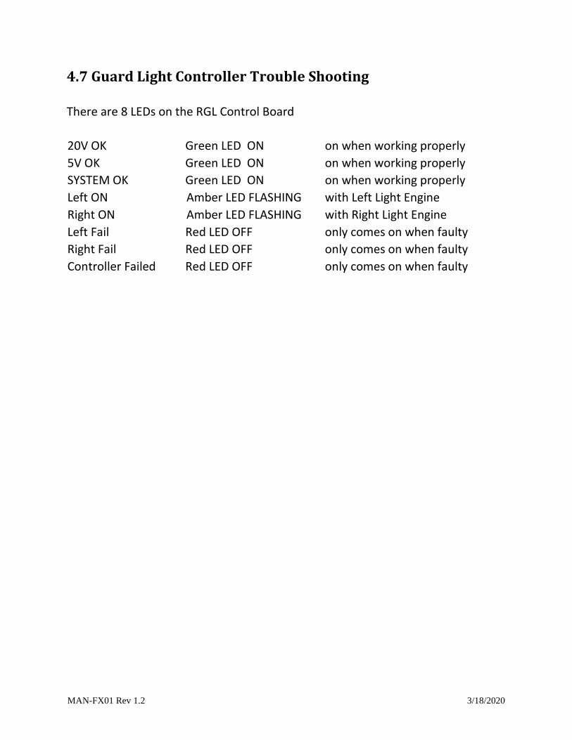
4.7 Guard Light Controller Trouble Shooting
There are 8 LEDs on the RGL Control Board
20V OK Green LED ON on when working properly
5V OK Green LED ON on when working properly
SYSTEM OK Green LED ON on when working properly
Left ON Amber LED FLASHING with Left Light Engine
Right ON Amber LED FLASHING with Right Light Engine
Left Fail Red LED OFF only comes on when faulty
Right Fail Red LED OFF only comes on when faulty
Controller Failed
Red LED OFF only comes on when faulty
MAN-FX01 Rev 1.2 3/18/2020
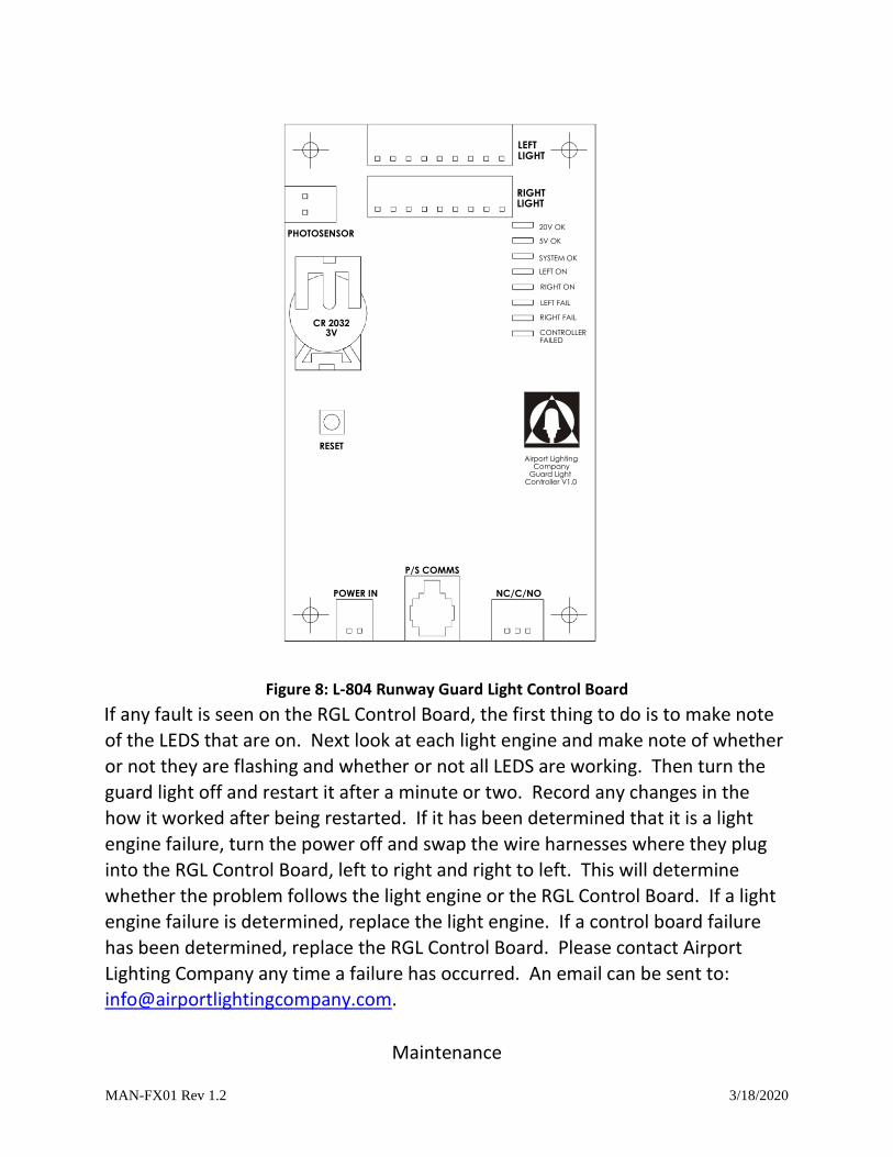
Figure 8: L-804 Runway Guard Light Control Board
If any fault is seen on the RGL Control Board, the first thing to do is to make note
of the LEDS that are on. Next look at each light engine and make note of whether
or not they are flashing and whether or not all LEDS are working. Then turn the
guard light off and restart it after a minute or two. Record any changes in the
how it worked after being restarted. If it has been determined that it is a light
engine failure, turn the power off and swap the wire harnesses where they plug
into the RGL Control Board, left to right and right to left. This will determine
whether the problem follows the light engine or the RGL Control Board. If a light
engine failure is determined, replace the light engine. If a control board failure
has been determined, replace the RGL Control Board. Please contact Airport
Lighting Company any time a failure has occurred. An email can be sent to:
Maintenance
Airport Lighting Company
Guard Light Controller V1.0
POWER IN NC/C/NO
RESET
PHOTOSENSOR
CR 2032 V 3
LEFT LIGHT
RIGHT LIGHT
P/S COMMS
20 V OK 5 V OK SYSTEM OK LEFT ON RIGHT ON LEFT FAIL RIGHT FAIL CONTROLLER FAILED
MAN-FX01 Rev 1.2 3/18/2020
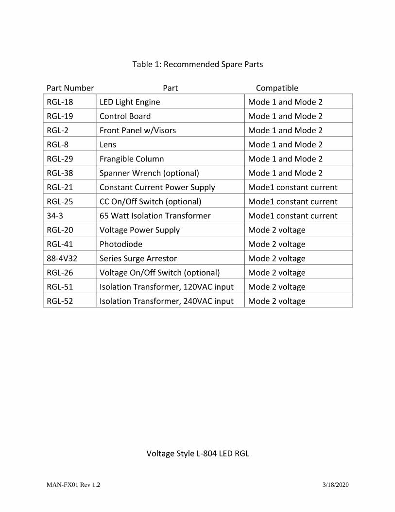
Table 1: Recommended Spare Parts
Part Number Part Compatible
RGL-18 LED Light Engine Mode 1 and Mode 2
RGL-19 Control Board Mode 1 and Mode 2
RGL-2 Front Panel w/Visors Mode 1 and Mode 2
RGL-8 Lens Mode 1 and Mode 2
RGL-29 Frangible Column Mode 1 and Mode 2
RGL-38 Spanner Wrench (optional) Mode 1 and Mode 2
RGL-21 Constant Current Power Supply Mode1 constant current
RGL-25 CC On/Off Switch (optional) Mode1 constant current
34-3 65 Watt Isolation Transformer Mode1 constant current
RGL-20 Voltage Power Supply Mode 2 voltage
RGL-41 Photodiode Mode 2 voltage
88-4V32 Series Surge Arrestor Mode 2 voltage
RGL-26 Voltage On/Off Switch (optional) Mode 2 voltage
RGL-51 Isolation Transformer, 120VAC input Mode 2 voltage
RGL-52 Isolation Transformer, 240VAC input Mode 2 voltage
Voltage Style L-804 LED RGL
MAN-FX01 Rev 1.2 3/18/2020
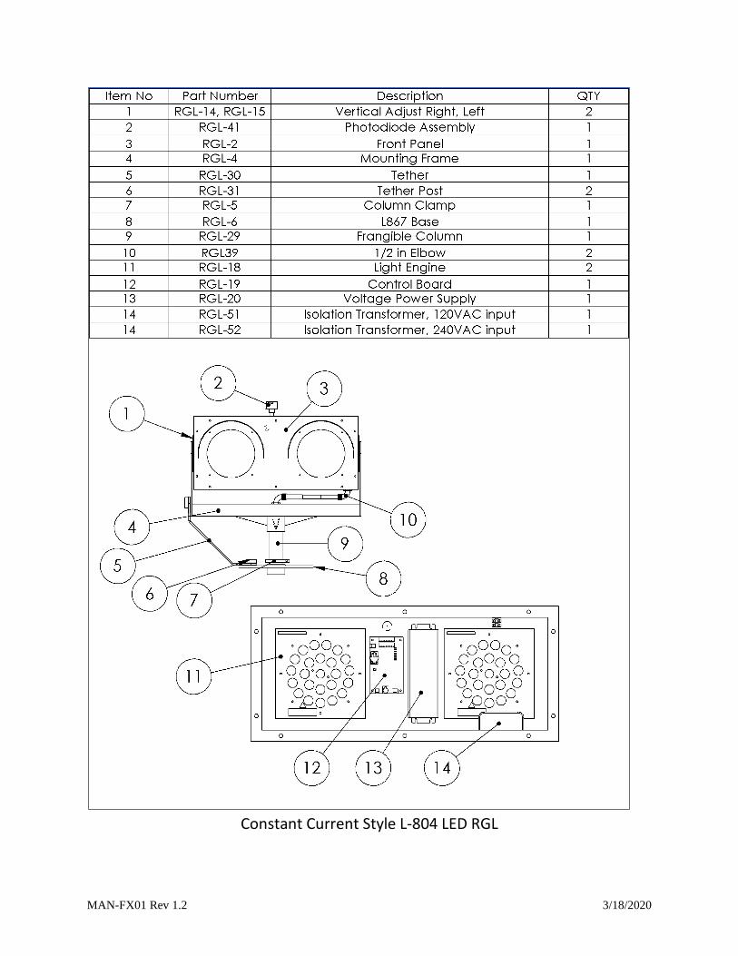
Constant Current Style L-804 LED RGL
MAN-FX01 Rev 1.2 3/18/2020
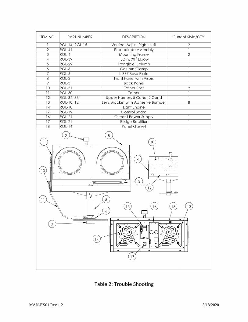
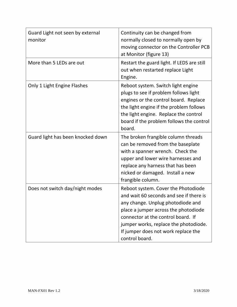
Table 2: Trouble Shooting
MAN-FX01 Rev 1.2 3/18/2020
Guard Light not seen by external
monitor
Continuity can be changed from
normally closed to normally open by
moving connector on the Controller PCB
at Monitor (figure 13)
More than 5 LEDs are out Restart the guard light. If LEDS are still
out when restarted replace Light
Engine.
Only 1 Light Engine Flashes Reboot system. Switch light engine
plugs to see if problem follows light
engines or the control board. Replace
the light engine if the problem follows
the light engine. Replace the control
board if the problem follows the control
board.
Guard light has been knocked down The broken frangible column threads
can be removed from the baseplate
with a spanner wrench. Check the
upper and lower wire harnesses and
replace any harness that has been
nicked or damaged. Install a new
frangible column.
Does not switch day/night modes Reboot system. Cover the Photodiode
and wait 60 seconds and see if there is
any change. Unplug photodiode and
place a jumper across the photodiode
connector at the control board. If
jumper works, replace the photodiode.
If jumper does not work replace the
control board.
MAN-FX01 Rev 1.2 3/18/2020
Mo
nit
ore
d (
wh
ite
)
LED
Lig
ht
En
gin
eLE
D L
igh
t En
gin
e
L804 Constant Current Power Supply
Bri
dg
e R
ec
tifie
r
L804 Control Board
Co
mm
un
ica
tio
n
Surge Arrestor
CC 6.6ACC 6.6A
Mo
de
1 -
Se
ries
Po
we
red
(cu
rre
nt
style
-no
mo
nito
r)
External Ground
CC
6.6
A (
bla
ck)
RG
L Fe
ma
le P
lug
De
tails
CC
6.6
A (
bla
ck)
Po
we
r
Co
nn
ec
tio
n
MAN-FX01 Rev 1.2 3/18/2020
Mo
nito
red
(w
hite
)
LED
Lig
ht
En
gin
eLE
D L
igh
t En
gin
e
L804 Constant Current Power Supply
Bri
dg
e R
ec
tifie
r
L804 Control Board
Co
mm
un
ica
tio
n
Surge Arrestor
CC 6.6ACC 6.6A
Mo
de
1 -
Se
rie
s P
ow
ere
d
(cu
rre
nt
style
-mo
nito
r)
Po
we
r
Co
nn
ec
tio
n
Mo
nito
red
(w
hite
)G
rou
nd
(b
lac
k)
CC
6.6
A (
bla
ck)
Mo
nito
red
(w
hite
)
CC
6.6
A (
bla
ck)
RG
L Fe
ma
le P
lug
De
tails
NC
/C/N
O
Ground
MonitorMonitor
MAN-FX01 Rev 1.2 3/18/2020
MAN-FX01 Rev 1.2 3/18/2020