led driver compact fixed output driver lc 20w 350/500 ... · the led driver is protected against...
TRANSCRIPT
www.tridonic.com 1Subject to change without notice.
Data sheet 05/18-LC453-1
LED Driver
Compact fixed output
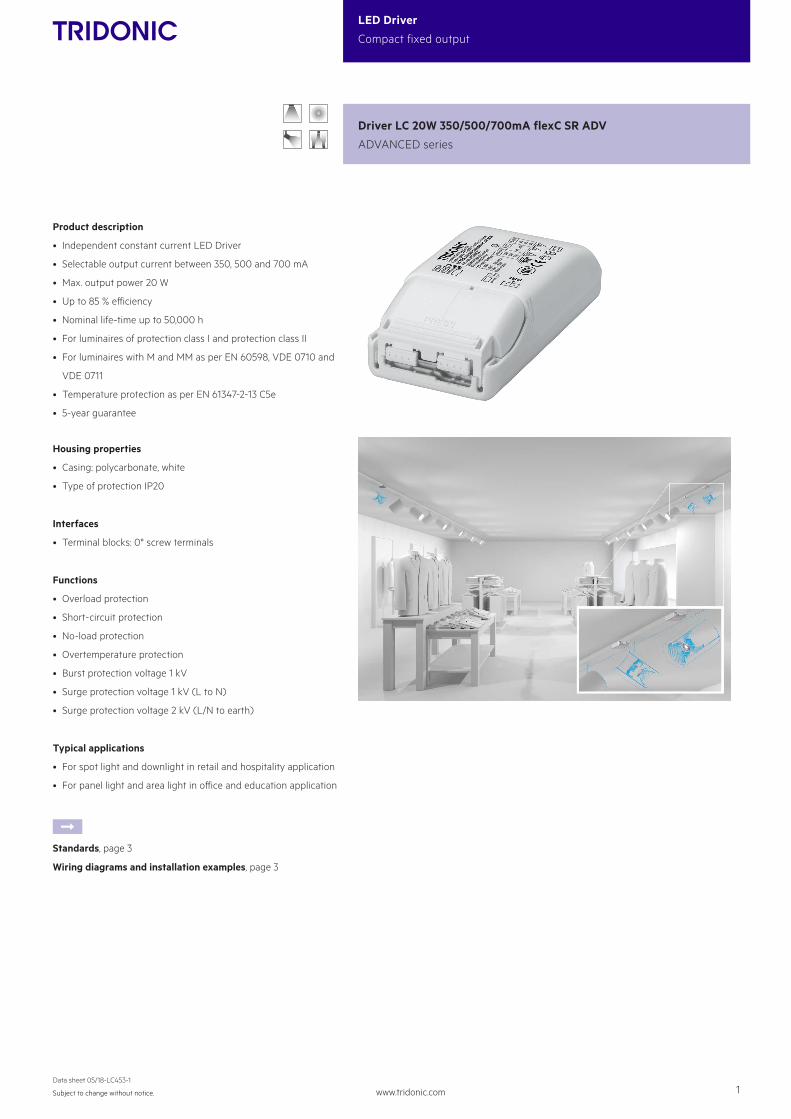
Product description
• Independent constant current LED Driver
• Selectable output current between 350, 500 and 700 mA
• Max. output power 20 W
• Up to 85 % efficiency
• Nominal life-time up to 50,000 h
• For luminaires of protection class I and protection class II
• For luminaires with M and MM as per EN 60598, VDE 0710 and
VDE 0711
• Temperature protection as per EN 61347-2-13 C5e
• 5-year guarantee
Housing properties
• Casing: polycarbonate, white
• Type of protection IP20
Interfaces
• Terminal blocks: 0° screw terminals
Functions
• Overload protection
• Short-circuit protection
• No-load protection
• Overtemperature protection
• Burst protection voltage 1 kV
• Surge protection voltage 1 kV (L to N)
• Surge protection voltage 2 kV (L/N to earth)
Typical applications
• For spot light and downlight in retail and hospitality application
• For panel light and area light in office and education application
ÈStandards, page 3
Wiring diagrams and installation examples, page 3
Driver LC 20W 350/500/700mA flexC SR ADV
ADVANCED series

www.tridonic.com 2Subject to change without notice.
Data sheet 05/18-LC453-1
LED Driver
Compact fixed output
Technical dataRated supply voltage 220 – 240 V
AC voltage range 198 – 264 V
Max. input current (at 230 V, 50 Hz, full load) 0.12 A
Leakage current (at 230 V, 50 Hz, full load) < 450 µA
Mains frequency 50 / 60 Hz
Overvoltage protection 320 V AC, 1 h
Max. input power 26 W
Typ. power consumption (at 230 V, 50 Hz, full load)1 24 W
Min. output power 8.7 W
Max. output power 20 W
Typ. efficiency (at 230 V / 50 Hz / full load)1 85 %
λ (at 230 V, 50 Hz, full load)1 0.95
Output current tolerance2 ± 10 %
Max. output current peak3 ≤ output current + 20 %
Max. output voltage 60 V
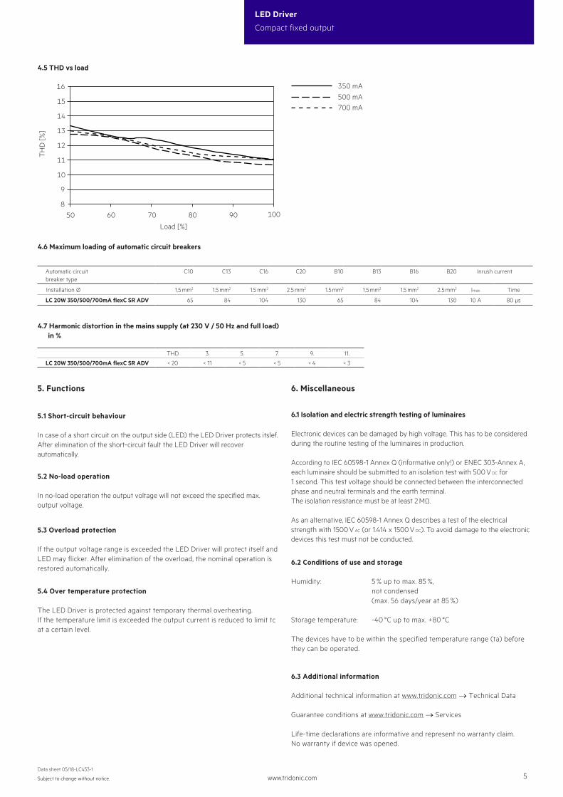
THD (at 230 V, 50 Hz, full load) < 20 %
Output LF current ripple (< 120 Hz) ± 5 %
Time to light (at 230 V, 50 Hz, full load) ≤ 1.2 s
Turn off time (at 230 V, 50 Hz, full load) ≤ 0.2 s
Hold on time at power failure (output) 0 s
Ambient temperature ta (at life-time 50,000 h) 40 °C
Storage temperature ts -40 ... +80 °C
Dimensions L x W x H 101.5 x 51 x 29.5 mm
Driver LC 20W 350/500/700mA flexC SR ADV
ADVANCED series
5120
101,5
3287
29,5
tc-point
4
156
tc-point
Ordering data
TypeArticle number
Packaging, carton
Packaging, low volume
Packaging, high volume
Weight per pc.
LC 20W 350/500/700mA flexC SR ADV 87500621 20 pc(s). 280 pc(s). 3,360 pc(s). 0.094 kg
Specific technical dataType Output
current2Min.
forward voltage
Max. forward voltage
Max. output power
Typ. power consumption (at 230 V, 50 Hz,
full load)
Typ. current consumption (at 230 V, 50 Hz,
full load)
Efficiency (at 230 V, 50 Hz,
full load)
Efficiency (at 230 V, 50 Hz,
min. load)
Max. casing temperature
tc
Ambient temperature ta
max.
LC 20W 350/500/700mA flexC SR ADV
350 mA 25 V 50.0 V 17.5 W 21 W 100 mA 85.0 % 78 % 80 °C -20 ... +50 °C
500 mA 20 V 40.0 V 20.0 W 24 W 110 mA 83.5 % 78 % 85 °C -20 ... +50 °C
700 mA 14 V 28.5 V 20.0 W 24 W 110 mA 82.0 % 75 % 85 °C -20 ... +50 °C
1 Test result at 700 mA.
2 Output current is mean value.
3 Test result at 25 °C.

www.tridonic.com 3Subject to change without notice.
Data sheet 05/18-LC453-1
LED Driver
Compact fixed output
1. Standards
EN 55015EN 60598-1EN 61000-3-2EN 61000-3-3EN 61347-1 EN 61347-2-13 EN 61547EN 62384
The LED Driver is designed for a life-time stated above under reference conditions and with a failure probability of less than 10 %.
2. Thermal details and life-time
2.1 Expected life-time
3. Installation / wiring
3.1 Circuit diagram
LC ... SR ADV
220–240 V
LN
LED
+
+ 700 mA+ LED 500 mA
50/60 Hz
SEC
PRI
–
ôô
+ 350 mA– LED
Iout
sele
ct
1.1 Glow wire test
according to EN 61347-1 with increased temperature of 850 °C passed.
Expected life-timeType Current ta 40 °C 50 °C
LC 20W 350/500/700mA flexC SR ADV
350 mAtc 70 °C 80 °C
Life-time 50,000 h 30,000 h
500 mAtc 75 °C 85 °C
Life-time 50,000 h 30,000 h
700 mAtc 75 °C 85 °C
Life-time 50,000 h 30,000 h
3.3 Fixing conditions
Dry, acidfree, oilfree, fatfree. It is not allowed to exceed the maximum ambient temperature (ta) stated on the device. Minimum distances stated below are recommendations and depend on the actual luminaire. Is not suitable for fixing in corner.
The LED module and all contact points within the wiring must be sufficiently insulated against 3 kV surge voltage.
3.4 Wiring guidelines
• All connections must be kept as short as possible to ensure good EMI behaviour.
• Mains leads should be kept apart from LED Driver and other leads (ideally 5 – 10 cm distance)• Max. lenght of output wires is 2 m.• Incorrect wiring can damage LED modules.• To avoid the damage of the Driver, the wiring must be protected against short circuits to earth (sharp edged metal parts, metal cable clips, louver, etc.).• The current selection has to be installed in the accordance to the requirement of low voltage installation.
>100 mmLeuchte
Luminaire >50 mm
>20
mm
max. ∅ = 8,0 mmmin. ∅ = 4,0 mm
0,5 – 2,5
4 – 5
3.2 Wiring type and cross section
The wiring can be in stranded wires with ferrules or solid. For perfect function of the cage clamp terminals the strip length should be 4 – 5 mm for the input terminal.The max. torque at the clamping screw (M3) is 0.2 Nm.
Input terminal (D2)
max. ∅ = 6,0 mmmin. ∅ = 2,0 mm
0,5 – 2,5
4 – 5
Output terminal (D1)
To get a proper working strain relief it is recommended that the cable jacket diameter of the side D2 is 2 mm bigger than the diameter of the side D1. (This can vary if the used cable jacket material varies from side D2 to D1 in pinching property).
D2D1
PRESS
Depending on the used flaps of the terminal following cable jacket diameter difference between the side D2 and D1 terminals is recommended:
Side D1 Side D2
Difference D2 - D1Housing bottom Cover terminal
With flap Without flap With flap Without flap With flap Without flap
x – x – x – 3.5 mm
x – x – – x 5.5 mm
x – – x – x 3.5 mm
– x x – – x 3.5 mm
– x – x – x 1.5 mm
x – – x x – 1.5 mm
– x x – x – 1.5 mm
– x – x x – -0.5 mm

www.tridonic.com 4Subject to change without notice.
Data sheet 05/18-LC453-1
LED Driver
Compact fixed output
3.7 Mounting of device
Max. torque for fixing: 0.5 Nm/M4
4. Electrical values
4.1 Efficiency vs load
74,0
76,0
78,0
80,0
82,0
84,0
86,0
50 70 80 9060 100
Load [%]
Eic
ienc
y [%
]
Test at 230 V 50 Hz.
4.2 Power factor vs load
0,84
0,86
0,88
0,90
0,92
0,94
0,96
0,98
50 70 80 9060 100
Load [%]
Pow
er fa
ctor
4.3 Input power vs load
10
24
80 90706050 100
20
14
18
16
22
12
Load [%]
Inpu
t pow
er [W
]
3.6 Current select
For 350 mA current use this terminals:
For 500 mA current use this terminals:
For 700 mA current use this terminals:
4.4 Input current vs load
50
120
80 907050 60 100
70
80
90
60
100
110
Load [%]
Inpu
t cur
rent
[mA
]
~~
L
N
LED
+
+ 700 mA+ LED 500 mA
–+ 350 mA– LED
~~
L
N
LED
+
+ 700 mA+ LED 500 mA
–+ 350 mA– LED
~~
L
N
LED
+
+ 700 mA+ LED 500 mA
–+ 350 mA– LED
3.5 Replace LED module
1. Mains off2. Remove LED module3. Wait for 20 seconds4. Connect LED module again
Hot plug-in or output switching of LEDs is not permitted and may cause a very high current to the LEDs.
www.tridonic.com 5Subject to change without notice.
Data sheet 05/18-LC453-1
LED Driver
Compact fixed output
Automatic circuitbreaker type
C10 C13 C16 C20 B10 B13 B16 B20 Inrush current
Installation Ø 1.5 mm2 1.5 mm2 1.5 mm2 2.5 mm2 1.5 mm2 1.5 mm2 1.5 mm2 2.5 mm2 Imax Time
LC 20W 350/500/700mA flexC SR ADV 65 84 104 130 65 84 104 130 10 A 80 µs
THD 3. 5. 7. 9. 11.
LC 20W 350/500/700mA flexC SR ADV < 20 < 11 < 5 < 5 < 4 < 3
4.6 Maximum loading of automatic circuit breakers
4.7 Harmonic distortion in the mains supply (at 230 V / 50 Hz and full load) in %
6.2 Conditions of use and storage
Humidity: 5 % up to max. 85 %, not condensed (max. 56 days/year at 85 %)
Storage temperature: -40 °C up to max. +80 °C
The devices have to be within the specified temperature range (ta) before they can be operated.
6.1 Isolation and electric strength testing of luminaires
Electronic devices can be damaged by high voltage. This has to be considered during the routine testing of the luminaires in production.
According to IEC 60598-1 Annex Q (informative only!) or ENEC 303-Annex A, each luminaire should be submitted to an isolation test with 500 V DC for 1 second. This test voltage should be connected between the interconnected phase and neutral terminals and the earth terminal. The isolation resistance must be at least 2 MΩ.
As an alternative, IEC 60598-1 Annex Q describes a test of the electrical strength with 1500 V AC (or 1.414 x 1500 V DC). To avoid damage to the electronic devices this test must not be conducted.
6.3 Additional information
Additional technical information at www.tridonic.com → Technical Data
Guarantee conditions at www.tridonic.com → Services
Life-time declarations are informative and represent no warranty claim.No warranty if device was opened.
5. Functions
5.1 Short-circuit behaviour
In case of a short circuit on the output side (LED) the LED Driver protects itslef. After elimination of the short-circuit fault the LED Driver will recover automatically.
5.2 No-load operation
In no-load operation the output voltage will not exceed the specified max. output voltage.
5.3 Overload protection
If the output voltage range is exceeded the LED Driver will protect itself and LED may flicker. After elimination of the overload, the nominal operation is restored automatically.
5.4 Over temperature protection
The LED Driver is protected against temporary thermal overheating. If the temperature limit is exceeded the output current is reduced to limit tc at a certain level.
6. Miscellaneous
4.5 THD vs load
8
16
50 9070 8060 100
9
10
11
13
12
14
15
Load [%]
TH
D [%
]
350 mA
700 mA500 mA