lecture 9 modulation, demodulation (detection): part 3 · quadratureamplitude modulation (qam)...
TRANSCRIPT

1
EE4900/EE6720 Digital Communications Suketu Naik
EE4900/EE6720: Digital Communications
Lecture 9
Modulation,
Demodulation
(Detection): Part 3

2
EE4900/EE6720 Digital Communications Suketu Naik
Block Diagrams of Communication System
Digital Communication System
Informatio
n (sound,
video, text,
data, …)
Transducer &
A/D ConverterModulator
Source
Encoder
Channel
Encoder
Tx RF
System
Output
Signal
D/A Converter
and/or output
transducer
DemodulatorSource
Decoder
Channel
Decoder
Rx RF
System
Channel

3
EE4900/EE6720 Digital Communications Suketu Naik
M-ary Quadrature
Amplitude Modulation
(QAM)

4
EE4900/EE6720 Digital Communications Suketu Naik
Quadrature Amplitude Modulation (QAM)
Applications
QAM (rhymes with Guam and VietNAM) is commonly
used in communications
Example1:
DOCSIS Cable modems use 64-QAM, 256-QAM for
downstream channel (to home) and QPSK, 16-QAM for
the upstream channel (from home)
Example 2:
Satellite TV and Military SatCOM use QAM

5
EE4900/EE6720 Digital Communications Suketu Naik
Quadrature Amplitude Modulation (QAM)
QAM: Amplitude and Phase of the baseband signal
changes BPSK: Binary Phase Shift Keying
(2 transitions, 1 bit/symbol)
QPSK: Quadrature Phase Shift Keying
(4 transitions, 2-bits/symbol)
8PSK:Eight Phase Shift Keying
(8 transitions, 3-bits/symbol)
16-QAM (16 transitions, 4-bits/symbol)
32-QAM (32 transitions, 5-bits/symbol)
64-QAM (64 transitions, 6-bits/symbol)
Example: 8PSK Time Domain

6
EE4900/EE6720 Digital Communications Suketu Naik
QAM: BPSK and QPSK
BPSK: Phase of the baseband signal changes from 0 deg
to 180 deg (2 transitions)=1 bit per symbolQ (out of phase)
I (in phase)Phase Diagram 01
QPSK: Phase of the baseband signal changes from 45
deg, 135 deg, 225 deg, 315 deg (4 transitions)=2 bits per
symbol Q (out of phase)
I (in phase)Phase Diagram
11
10
01
00
Radius= 𝑬𝒂𝒗𝒈
Radius= 𝑬𝒂𝒗𝒈
M=2, 1-bit
Eavg=A2
M=4, 2-bits
Eavg=A2

7
EE4900/EE6720 Digital Communications Suketu Naik
QAM: 8-PSK and 4-QAM
8PSK = 8 phase transitions= 3 bits per symbol
4-QAM = 4 transitions = 2-bits/symbol
8-PSK Phase
Diagram
4-QAM
Phase Diagram
Q (out of phase)
I (in phase)
I (in phase)
Q (out of phase)
Radius= 𝑬𝒂𝒗𝒈
M=8, 3-bits
Eavg=A2
M=4, 2-bits
Eavg=2A2

8
EE4900/EE6720 Digital Communications Suketu Naik
QAM: 16-PSK and 32-QAM 16-QAM = 16 transitions = 4-bits/symbol
64-QAM = 64 transitions = 6-bits/symbol
64-QAM
Phase Diagram
Q (out of phase)
I (in phase)
I (in phase)
Q (out of phase)
16-QAM
Phase Diagram
M=16, 4-bits
Eavg=10A2
M=64, 6-bits
Eavg=42A2
9
EE4900/EE6720 Digital Communications Suketu Naik
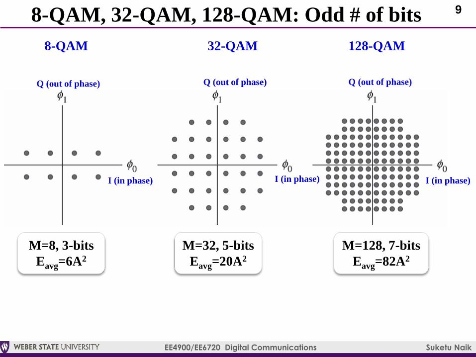
8-QAM, 32-QAM, 128-QAM: Odd # of bits
Q (out of phase)
I (in phase)
8-QAM
M=8, 3-bits
Eavg=6A2
Q (out of phase)
I (in phase)
32-QAM 128-QAM
Q (out of phase)
I (in phase)
M=32, 5-bits
Eavg=20A2
M=128, 7-bits
Eavg=82A2

10
EE4900/EE6720 Digital Communications Suketu Naik
Continuous-time QAM

11
EE4900/EE6720 Digital Communications Suketu Naik
Continuous-time M-ary QAM Basics
M-ary QAM is a 2-dimensional signal
Basis function=unit energy pulse x sinusoid
Sinusoids (cosine and sine) are 90°out of phase with
each other (hence the name Quadrature)
QAM signal s(t) with k symbols*
𝝓𝟎(𝒕) = 𝟐𝒑 𝒕 𝐜𝐨𝐬 𝝎𝟎𝒕
𝝓𝟏(𝒕) = − 𝟐𝒑 𝒕 𝐬𝐢𝐧 𝝎𝟎𝒕
𝒔 𝒕 = 𝑰 𝒕 𝟐𝐜𝐨𝐬 𝝎𝟎𝒕 − 𝑸 𝒕 𝟐 𝐬𝐢𝐧 𝝎𝟎𝒕where,
𝑰 𝒕 =
𝒌
𝒂𝟎 𝒌 𝒑(𝒕 − 𝒌𝑻𝒔)
𝑸 𝒕 =
𝒌
𝒂𝟏 𝒌 𝒑(𝒕 − 𝒌𝑻𝒔)
In phase (‘Eye’)
Out-of-phase (‘Cue’)
*= the book often switches between notation k and M. Here we will assume that k=M. For example, 16-QAM has M=16
and k=16 symbols

12
EE4900/EE6720 Digital Communications Suketu Naik
M-ary QAM Signal
kth QAM symbol in Rectangular and Polar Forms
Rect. Form: 𝒂𝟎 𝒌 𝒑(𝒕 − 𝒌𝑻𝒔) 𝟐𝐜𝐨𝐬 𝝎𝟎𝒕 − 𝒂𝟏 𝒌 𝒑(𝒕 − 𝒌𝑻𝒔) 𝟐 𝐬𝐢𝐧 𝝎𝟎𝒕
Polar Form: 𝒂𝟎𝟐 𝒌 + 𝒂𝟏
𝟐 𝒌 𝒑(𝒕 − 𝒌𝑻𝒔) 𝟐 𝐜𝐨𝐬 𝝎𝟎𝒕 + 𝒕𝒂𝒏−𝟏𝒂𝟏 𝒌
𝒂𝟎 𝒌
Amplitude changes Phase changes
In Phase (I) Out-of-phase (Q)
8PSK signalkth QAM symbol

13
EE4900/EE6720 Digital Communications Suketu Naik
Continuous-time QAM Modulator
Basis
Function
ϕ0(t)
Basis
Function ϕ1(t)
Example: 16-QAM
Constellation

14
EE4900/EE6720 Digital Communications Suketu Naik
Continuous-time QAM Demodulator

15
EE4900/EE6720 Digital Communications Suketu Naik
Continuous-time QPSK Modulator

16
EE4900/EE6720 Digital Communications Suketu Naik
Continuous-time QPSK Demodulator
I & Q signals
corrupted by noise
Eye Diagram
Eye Diagram
Eye Diagram
Eye Diagram

17
EE4900/EE6720 Digital Communications Suketu Naik
Continuous-time QPSK: Eye DiagramQPSK 16-QAM
QPSK 16-QAM
α=1
(100%
excess BW)
α=0.5
(100%
excess BW)
SRRC Pulse

18
EE4900/EE6720 Digital Communications Suketu Naik
Problems: Phase Offset and Symbol Timing Error
1) Uncompensated carrier phase
offset can distort the constellation
and ‘corrupt’ the received bits
- Counterclockwise
(CCW) rotation of °How to compensate?
Carrier Phase Synchronization
(Ch7)
2) Matched filter output: where is
the starting sample?
How to start?
Symbol Timing Synchronization
(Ch8)
Rotation of constellation due
to carrier phase offset
Scattered constellation points due to
symbol timing error

19
EE4900/EE6720 Digital Communications Suketu Naik
Discrete-time QAM

20
EE4900/EE6720 Digital Communications Suketu Naik
Discrete-time QAM Modulator
Basis Function
ϕ0(t)
Example: 16-QAM
Constellation
Basis
Function ϕ1(t)
Direct Digital Synthesizer

21
EE4900/EE6720 Digital Communications Suketu Naik
Discrete-time QAM Modulator
We replace t with nT where n=sample index, T=sampling time
We will also up-sample and down-sample the symbol amplitudes
by factor N (insert N-1 zeros between each sample)
Discrete-time I and Q signals: Eq. 5.83, Eq. 5.84, Eq. 5.85
Next, the I & Q signals are passed through discrete-time pulse-
shaping filter which interpolates the samples (inserted zeros now
change into samples): pulse=samples of impulse response h(t)
Next, the interpolated I & Q signals are multiplied with discrete-
time sinusoids (cosine and sine): frequency of the sinusoids, Eq. 5.86
Finally, we add the I & Q signals and create a QAM signal, which
is passed through DAC and transmitted using a carrier signal
22
EE4900/EE6720 Digital Communications Suketu Naik
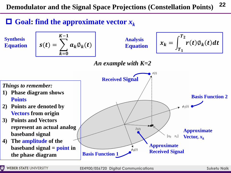
Demodulator and the Signal Space Projections (Constellation Points)
𝒔(𝒕) =
𝒌=𝟎
𝑲−𝟏
𝒂𝒌∅𝒌(𝒕)𝒙𝒌 = න
𝑻𝟏
𝑻𝟐
𝒓 𝒕 ∅𝒌 𝒕 𝒅𝒕
Goal: find the approximate vector xk
Analysis
Equation
Synthesis
Equation
Received Signal
Approximate
Received Signal
Basis Function 2
Basis Function 1
Approximate
Vector, xk
An example with K=2
Things to remember:
1) Phase diagram shows
Points
2) Points are denoted by
Vectors from origin
3) Points and Vectors
represent an actual analog
baseband signal
4) The amplitude of the
baseband signal = point in
the phase diagram
23
EE4900/EE6720 Digital Communications Suketu Naik
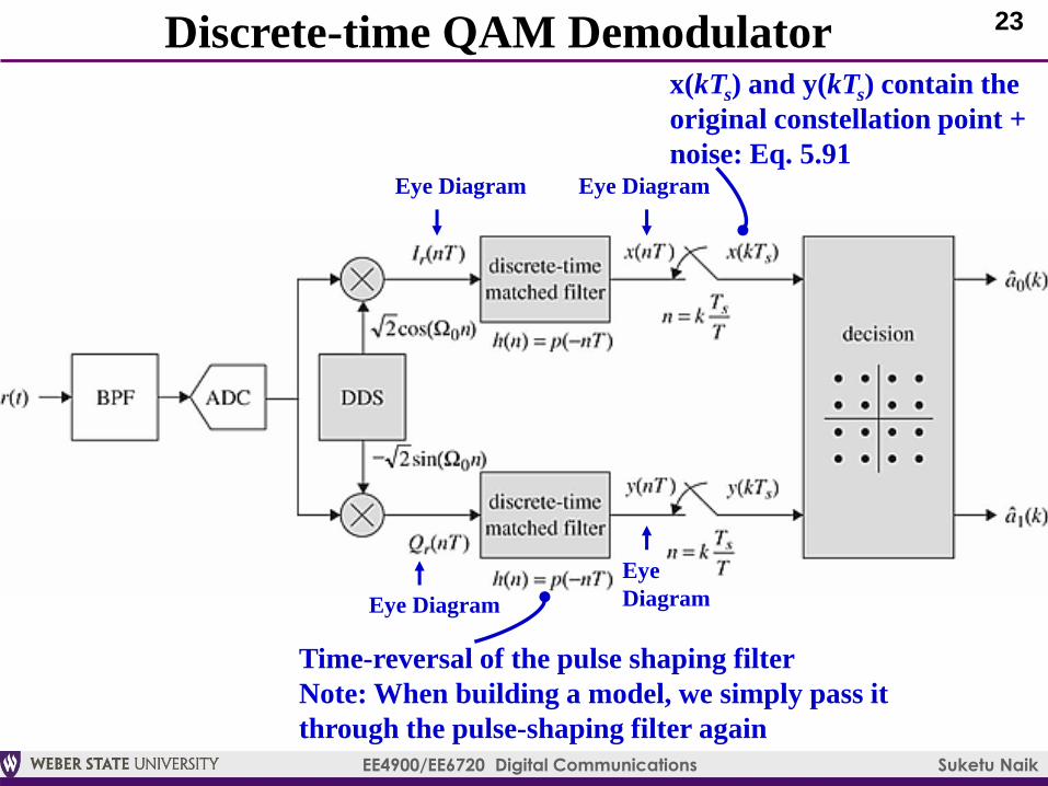
Discrete-time QAM Demodulator
Time-reversal of the pulse shaping filter
Note: When building a model, we simply pass it
through the pulse-shaping filter again
x(kTs) and y(kTs) contain the
original constellation point +
noise: Eq. 5.91Eye Diagram
Eye Diagram
Eye Diagram
Eye
Diagram

24
EE4900/EE6720 Digital Communications Suketu Naik
Problems: Phase Offset, ADC Sampling Rate, Symbol Timing Error
1) Uncompensated carrier phase
offset can distort the constellation
and ‘corrupt’ the received bits
- Counterclockwise (CCW)
rotation of °How to compensate?
Carrier Phase Synchronization (Ch7)
2) ADC sample rate is not an integer
multiple of symbol rate.
How to match sampling rates?
Resampling Filters (Ch9)
3) Matched filter output: where is
the starting sample?
How to start?
Symbol Timing Synchronization
(Ch8)
Rotation of constellation due
to carrier phase offset
Dispersed constellation points due to
symbol timing error

25
EE4900/EE6720 Digital Communications Suketu Naik
Assignment 4 [10]
Simulate BPSK Communication System in Simulink and
decode the secret message [10]
Build the following:
Modulator (for testing demodulator)
Demodulator
Submit the following:
1) Simulink models
2) Time-domain plots
3) Eye-diagram and Constellation
4) Decoded Message
26
EE4900/EE6720 Digital Communications Suketu Naik
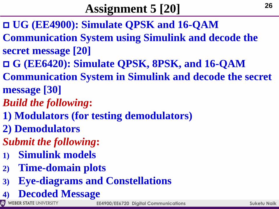
Assignment 5 [20]
UG (EE4900): Simulate QPSK and 16-QAM
Communication System using Simulink and decode the
secret message [20]
G (EE6420): Simulate QPSK, 8PSK, and 16-QAM
Communication System in Simulink and decode the secret
message [30]
Build the following:
1) Modulators (for testing demodulators)
2) Demodulators
Submit the following:
1) Simulink models
2) Time-domain plots
3) Eye-diagrams and Constellations
4) Decoded Message