maintaining an all digital plant - iowa heartland chapter · pdf filemaintaining an all...
TRANSCRIPT

Maintaining an All Digital Plant
Presenter: Tony Holmes
SCTE Iowa Heartland Chapter

Technical Session Overview
Physical Layer (PHY) metrics used by operators to measure
digital health
QAM performance metrics that are used to asses the
forward and return paths
Network layer metrics used to measure digital health at the
service level
Possible Physical and Network layer causes
DOCSIS 3.0 Existing technology
DOCSIS 3.1 Introduction
2

CATV HFC Network
TV
STB
VoIP
Router
CMTS
Internet
Head End
VoD
Satellite
PSTN
Voice
Gateway
DOCSIS
Modem
DHCP
server
TOD
server
TFTP
server
Data
Return Path / Reverse Path
HDTV, HSD, SDV, VoIP, Broadband revenue
generating services are made possible by Digital
Cable Services.
IPTV
O/E
Forward Path
3

Analog vs. Digital
Analog DigitalVideo
Audio
Haystack
Video and two audio channels are
modulated to three separated frequencies
within a 6MHz bandwidth.
They are transmitted at different levels.
Normally, a video channel is about 10dB
higher than the audio channels.
Signals are in analog nature, therefore,
will tolerate more sustained noise however
the picture will degrade.
Video and audio signals are digitized to digital
0 and 1, QPSK or QAM-16/64/256 modulated,
then transmit in a 6MHz band.
Digital symbols (bits) are embedded in the
Haystack.
High digital bit rates can be transmitted in a
6MHz band for up to 40Mbps suitable for
internet, VoIP, or HDTV services.
Noise can affect the digital bit streams.
Uses FEC (forward error correction) to correct
errors caused by noise.
4

Digital Signal Modulation
Modulation algorithms:
QPSK - Quadrature Phase Shift Keying
QAM - Quadrature Amplitude Modulation
QPSK has been used for many years and is the same as
QAM-4.
QAM modulates both phase and amplitude with more
levels to achieve higher bit rate than QPSK, for example;
QAM-16, -64, -128,-256, and -1024
5

Forward Error Correction (FEC)
Adds additional information (data) to the original data stream
The additional information is generated by using Reed Solomon encoder
calculated from the original data stream before transmitting
By using the same Reed Solomon decoder at the receiving end, bit errors can
be detected as are called Pre-FEC errors
By going through the error correction
algorithm, some Pre-FEC errors can
be corrected. When Pre-FEC errors
become significant and some errors
can be not corrected, they are called
Post-FEC errors
Post-FEC errors cause the poor TV
quality or Internet data
retransmission. (Slow Speeds!)
6

Most visible on digital
transmission (Digital Cable TV,
Satellite TV, over-the-air
terrestrial TV)
Image perfect until saturation
Sudden degradation in quality
Pixelization, frozen frames
The Cliff Effect – Analog vs. Digital
7

Effect of noise on Analog Systems (Gradually Poorer C/N)
45dB C/N 35dB C/N 25dB C/N 20dB C/N
Noise has very little effect on Digital systems until the system
fails completely. (Digital Channel with a QAM256)
35dB MER 32dB MER 30dB MER 28dB MER
Effect of noise on Digital Systems (Gradually Poorer MER)
Digital TV vs. Analog TV
8

QAM – Constellation Diagram
Each box in the constellation diagram contains one symbol
QAM64: 6 bits per symbol, 64 boxes
QAM256: 8 bits per symbol, 256 boxes
Quadrant 1
Quadrant 2Quadrant 3
Quadrant 4
9

HFC Forward Path
Modulation
type
Std. Symbol
Rate (MHz)
Max data rate
(Mbps)
Annex A
(8MHz)
QAM64 6.952 41.4
Annex A
(8MHz)
QAM256 6.952 55.2(440 max 8 Ch bonding)
Annex B
(6MHz)
QAM64 5.057 38
Annex B
(6MHz)
QAM256 5.361 43(320M @ 8 Ch bonding)
(800M @ 20 ch bonding)
QAM 64 or QAM 256 are commonly used
10

HFC Return Path – DOCSIS
DOCSIS Bandwidth
(MHz)
Modulation
type
Max data rate
(Mbps)
1.0 3.2 QPSK 5.12
1.1 3.2 QPSK
QAM-16
5.12
10.24
2.0 6.4 QAM-16
(QAM-64)
10.24
30.72
3.0 6.4 QAM-16
(QAM-64)
10.24
120 (4 channel bonding)
3.1 OFDM 10+Gbps DS
1+ Gbps US
DOCSIS (Data-Over-Cable Service Interface Specifications)
Reverse Path / Upstream Data Rate
Standard symbol rate (bandwidth): 1.28 (1.6), 2.56 (3.2), 5.12 (6.4) MHz11

Measuring Analog Channels
1. Video and audio signal levels
2. Carrier to Noise
3. Adjacent channel and HUM
4. More advanced meter measures CSOs and CTB
12

Measuring Digital Channels
1. Signal Level, MER
2. Checks for Pre and Post FEC errors = 0
75
531 MHz
13

Tiling, what is the problem ?
What does our signal level meter and
spectrum analyzer tell us about the digitally
modulated signal on Channel 75 (531
MHz)?
Its average power level is +4.6
dBmV
The “haystack” looks OK
Hmmm, must be the STB!
75
531 MHz
14

What’s missing ?
While a signal level meter and conventional spectrum
analyzer are valuable tools, they don’t tell the whole story
about the health of downstream and upstream digitally
modulated signals.
How, then, can one “look inside” the haystack to see what’s
going on?
15
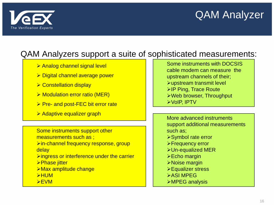
QAM Analyzer
QAM Analyzers support a suite of sophisticated measurements:
Analog channel signal level
Digital channel average power
Constellation display
Modulation error ratio (MER)
Pre- and post-FEC bit error rate
Adaptive equalizer graph
Some instruments support other
measurements such as ;
in-channel frequency response, group
delay
ingress or interference under the carrier
Phase jitter
Max amplitude change
HUM
EVM
Some instruments with DOCSIS
cable modem can measure the
upstream channels of their;
upstream transmit level
IP Ping, Trace Route
Web browser, Throughput
VoIP, IPTV
More advanced instruments
support additional measurements
such as;
Symbol rate error
Frequency error
Un-equalized MER
Echo margin
Noise margin
Equalizer stress
ASI MPEG
MPEG analysis
16
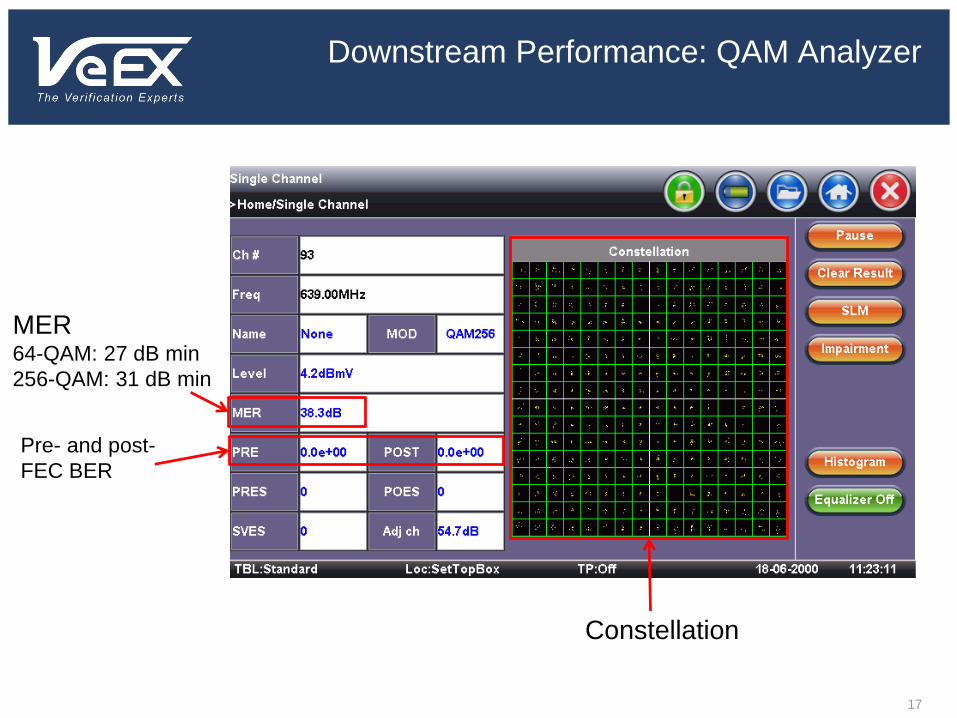
Downstream Performance: QAM Analyzer
Pre- and post-
FEC BER
MER64-QAM: 27 dB min
256-QAM: 31 dB min
Constellation
17

Downstream Performance: Pre/Post-FEC
BER
In this example, digital channel power,
MER and the constellation are fine, but
pre- and post-FEC BER indicate a
problem—perhaps sweep transmitter
interference, downstream laser clipping,
an upconverter problem in the headend,
or a loose connection at the customer
premise.
18

Modulation Quality: Modulation Error Ratio
Modulation error = Transmitted symbol – Target symbol
Source: Hewlett-Packard
Modulation error
Transmitted (or received)
symbol
Target symbol
Q
I
19

Modulation Error Ratio
MER = 10log(average symbol power/average error power)
Average symbol
power
I
Q
Average error power
Source: Hewlett-Packard
I
Q
I
Q
A large “cloud” of
symbol points means
low MER—this is not
good!
A small “cloud” of
symbol points
means high MER—
this is good!
N
jjj
N
jjj
QI
QIMER
1
22
1
22
10log10
20

Intermittent Troubles
21

Constellation Display
Poor CNR or low MER I-Q imbalance
22
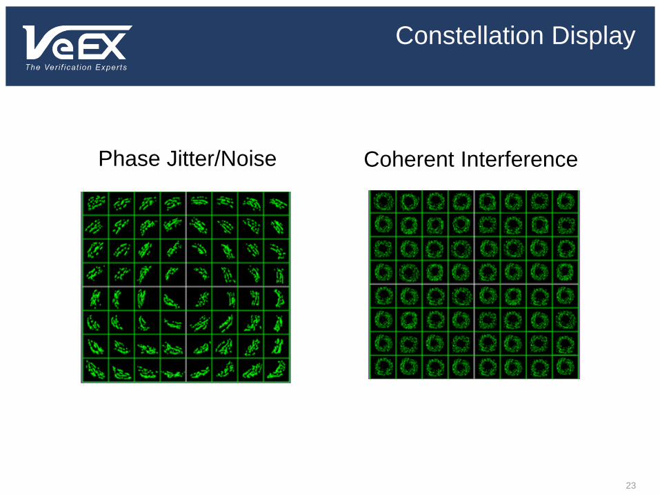
Constellation Display
Phase Jitter/Noise Coherent Interference
23

Constellation Display
Gain compressionGain compression
Upstream Laser Clipping
24

Constellation Display
Quadrature distortion Zoom function
25
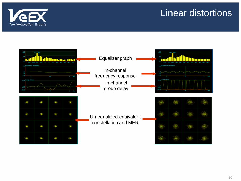
Linear distortions
Equalizer graph
In-channel
frequency response
In-channel
group delay
Un-equalized-equivalent
constellation and MER
26

Linear distortions
Micro-reflection at about 2.5 µs (2500 ns):
Assume ~1 ns per ft., 2500/2 = 1250 ft
(actual is 1.17 ns per ft: (2500/1.17)/2 = 1068 ft)
Frequency response ripple ~400 kHz p-p:
Distance to fault = 492 x (.87/.400) = 1070 ft.
27
Linear Distortions: In-depth understandings
ECHO MARGINThe Coefficients of the Equalizer will also reveal the presence of an Echo, (a.k.a. micro-reflections). The Equalizer will cancel such an echo, and in doing so, the equalizer coefficient which corresponds to the delay of the echo will be much higher than the surrounding ones, “it sticks out of the grass”. The relative amplitude of this coefficient is an indication of the seriousness of the echo, and its position gives the delay of the echo, hence its roundtrip distance.The Echo Margin is the smallest difference between any coefficients and a template defined by Cablelabs, as a safety margin before getting too close to the “cliff effect”. It is normal to notice relatively high coefficients close to the Reference as this corresponds to the filters in the modulator / demodulator pair and to the shape of QAM signal.
28

EQUALIZER STRESS
The Equalizer Stress is derived from the Equalizer coefficients and indicate how much the Equalizer has to work to cancel the Linear distortions, it is a global indicator of Linear distortions. The higher the figure, the less stress.
NOISE MARGIN
We all know that the lower the MER, the larger the probabilities of errors in transmission (Pre-FEC and then Post-FEC); the MER degrades until errors are so numerous that adequate signal recovery is no more possible (cliff effect). As Noise is a major contributor to the MER, we define Noise Margin as the amount of noise that can be added to a signal (in other words, how much we can degrade MER) before get dangerously close to the cliff effect. Noise is chosen because on the one hand it is always present, and on the other hand it is mathematically tractable. Other impairments, such as an Interferer, are not easily factored into error probabilities.
29
Linear Distortions: In-depth understandings
EQUALIZED MER vs. UN-EQUALIZED MER
The MER (Modulation Error Ratio) is the ratio of the QAM signal to Non-Linear distortions of the incoming QAM signal. The MER should have included the Linear distortions to indicate the health of the signal; but the QAM demodulator cannot operate properly without the Equalizer and the Equalizer uses the MER as a tool to adaptively cancel the Linear distortions. Consequently it is convenient to distinguish the MER (non-linear distortions only) from an Un-equalized MER (non-linear and linear distortions), the Un-equalized MER is calculated from the MER and Equalizer Stress.The Un-equalized MER is always worst than the MER. A small difference between the two indicates little Linear distortions, a large difference shows that there are strong Linear distortions. Even if the Linear distortions are cancelled by the Equalizer, we have to keep in mind that the Equalization is a dynamic process as it tracks Linear distortions by trial and error even after converging. The larger the Linear distortions the larger the tracking transients are, hence more probability of transmission error (pre-FEC or Post-FEC BER).
30
Linear Distortions: In-depth understandings

Linear Distortions: In-depth understandings
PHASE JITTERPhase Jitter is caused by instability of the carrier of the QAM signal at the demodulator. This instability could be found at the QAM modulator and up-converter or in the QAM receiver (Local Oscillators used in frequency conversions). The phase jitter introduces a rotation of the constellation, where the symbols clusters elongate and get closer to the symbol’s boundary. Eventually some symbols will cross the boundary and cause an error in transmission. The QAM demodulator has a Phase lock loop to track phase variations of the carrier; it tracks easily long term drift as well as some short terms variations (up to 10 or 30 kHz) but it cannot track very fast variations above its loop response. So in a QAM demodulator, the wideband jitter is more damageable than short term jitter.
31

Linear Distortions: Recommendations
Assumed Downstream RF Channel Characteristics DOCSIS Radio Frequency Interface Specifications
Parameter Value
Carrier-to-noise ratio in a 6 MHz band Not less than 35 dB
Carrier-to-composite triple beat distortion ratio Not less than 41 dB
Carrier-to-composite second order distortion ratio Not less than 41 dB
Carrier-to-any other discrete interference Not less than 41 dB
Amplitude ripple 3 dB within the design bandwidth
Group delay ripple in the spectrum occupied 75 ns within the design bandwidth
Micro-reflections bound for dominant echo -10 dBc @ <= 0.5 µs
-15 dBc @ <= 1.0 µs
-20 dBc @ <= 1.5 µs
-30 dBc @ > 1 .5 µs
Carrier hum modulation Not greater than -26 dB (5%)
Assumed Upstream RF Channel Characteristics DOCSIS Radio Frequency Interface Specifications
Parameter Value
Carrier-to-interference plus ingress ratio Not less than 25 dB
Amplitude ripple 0.5 dB / MHz
Group Delay ripple 200 ns / MHz
Micro-reflections bound for dominant echo -10 dBc @ <= 0.5 µs
-20 dBc @ <= 1.0 µs
-30 dBc @ > 1 .5 µs
TABLE 2 DOCSIS SPECIFICATIONS, UPSTREAM
TABLE 1 DOCSIS SPECIFICATIONS, DOWNSTREAM
32

Other Factors Harm QAM…Ingress!!
Confidential & Proprietary Information of VeEX Inc. 33

Measurement and Troubleshooting Summary
• Constellation display– Low MER or CNR
– Phase noise
– I-Q imbalance
– Coherent interference (ingress, beats)
– Gain compression
– Laser clipping
– Sweep transmitter interference
• Pre- and post-FEC BER– Sweep transmitter interference
– Laser clipping
– Loose connections
– Low MER or CNR
• Equalizer graph– Micro-reflections
• Linear distortionsAdaptive equalizer graph
In-channel frequency response
In-channel group delay
Constellation display (unequalized)
MER (unequalized)
• Transient impairmentsPre- and post-FEC BER
Constellation display zoom function
Upstream packet loss
• Signal level problemsAnalog TV channel signal level
Digital channel power
Upstream transmit level
Constellation display
34

Up/Downstream Performance – Cable Modem
What Digital Impairments do to Data
Proper IP connection and
throughput should be verified at
the cable modem service
location.
Web Browsing
Ping
Speed Tests
35

Obvious Packet Loss Issue
36
• Many Lost Packets
• Out of Control Delay

Modem Bonding Group Performance
37

Speed TestingVerify Down/Upload Performance
38
Cable Modem or
Ethernet Interface

DOCSIS 3.0 existing technology
Confidential & Proprietary Information of VeEX Inc. 39Presentation Name Here

DOCSIS system
Enables transparent bi-directional of Internet Protocol (IP) traffic, between the cable system headend and
customer location
DOCSIS specification
Defines PHY & MAC layer protocols for communication & Ethernet frame transport between CMTS & CM
DOCSIS network comprises:
Cable Modem Termination System (CMTS) located at the headend
Cable Network - an all-coaxial or hybrid-fiber/coax (HFC) cable network
Cable Modem (CM) located at the Customer Premise
An Overview
DOCSIS
DOCSIS® Confidential & Proprietary Information of VeEX Inc 40
Transparent IP traffic
Wide Area
NetworkCable Network
(HFC)
CMTS Cable Modem CPE
CM/CPE
Interface
CMTS/WAN
Interface

Milestones
DOCSIS
DOCSIS 1.0 (1999)
• 1st products certified (CableLabs started project in 1996)
• Open standard for high-speed data over cable
• Modest security, Best-effort service
DOCSIS 1.1 (2000)
• Quality-of-Service (QoS) service flows
• Baseline Privacy Interface (BPI+) Certificates
• Improved privacy & encryption process
DOCSIS 2.0 (2002)
• Improved throughput & robustness on Upstream
• 64/128 QAM modulation & higher symbol rates with FEC
• Programmable interleaving to upstream channels
DOCSIS 3.0 (2006)
• Channel bonding (4U/4D) for increased capacity
• IPv6 support
• Improved security (AES)
DOCSIS® 41Confidential & Proprietary Information of VeEX Inc

Support high bandwidth services of 50 to 100Mbps
Migrate existing customers to higher tier services
Better and more robust data encryption
Provide more IP address space using IPv6
Limit and reduce node splits
Reduce overall cost of CMTS ports
Independent scalability of upstream & downstream
Business Drivers
DOCSIS 3.0
DOCSIS® Confidential & Proprietary Information of VeEX Inc 42

Higher Bandwidth Applications
DOCSIS 3.0
Digital
Photos
Gaming
MP3
WMV
DVD
Blu-ray
SDTV
HDTVMobile
Video
iPod
Walkman
You Tube
VOD
DVR/PVR
Data &
VoIP
Home
Networks
Web 2.0
DOCSIS® 43Confidential & Proprietary Information of VeEX Inc
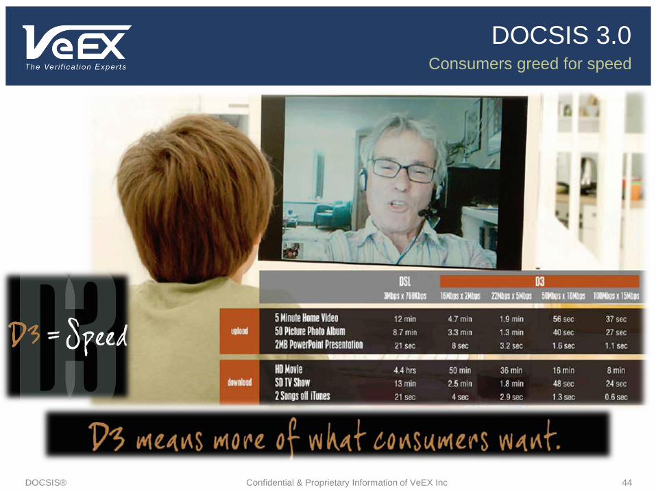
Consumers greed for speed
DOCSIS 3.0
44DOCSIS® Confidential & Proprietary Information of VeEX Inc

High bandwidth residential data and content
Video and photo uploads
Proliferation of social networking sites and applications
IP “Video over DOCSIS” (VDOC)
High definition Video to multiple devices
PCs, hybrid STBs, portable devices
High bandwidth Internet streaming
High Bandwidth Video conferencing
Cisco TelePresence
Commercial service
High bandwidth symmetrical data services
Bonded E1/T1 circuit emulation
High bandwidth Ethernet / L2VPN services
Services driving Channel Bonding
DOCSIS 3.0
DOCSIS® Confidential & Proprietary Information of VeEX Inc 45

Major Feature Overview
DOCSIS 3.0
• Bonded Downstream Channels
• 56Mbps (RAW) each, 448Mbps TotalIncreased DS bandwidth
• Bonded Upstream Channels
• 27Mbps (RAW) each, 122Mbps Total Increased US bandwidth
• IPV6 allows for 3.4x1038 IP addresses
• IP addresses are lengthened from 32 bits to 128 bitsIPv6
• Existing DOCSIS 1.0, 1.1 and 2.0 systems
• Scalable deployment with easy subscriber migrationBackwards compatibility
• IPTV-type applications
• Efficient “switched-video-like” bandwidth usageIP Multicast
• E1 & T1 circuit emulation Commercial
• Early Authentication and Encryption (EAE) and AES 128bit encryption which is more robust and secure
Network Security
DOCSIS® 46Confidential & Proprietary Information of VeEX Inc

Channel bonding basically means data is transmitted to/from Cable Modems
using multiple individual RF channels instead of a single channel
DS Channel Bonding
DOCSIS 3.0
DOCSIS® Confidential & Proprietary Information of VeEX Inc 47
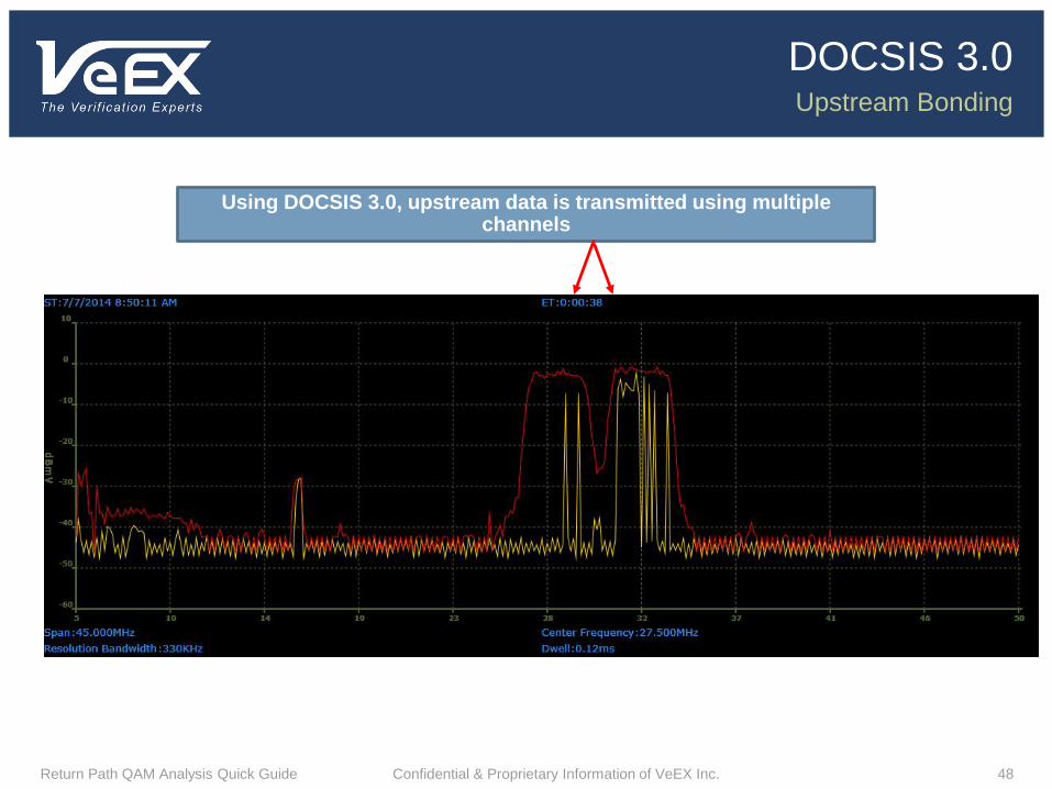
Using DOCSIS 3.0, data is transmitted to cable modems using multiple channels
Upstream Bonding
DOCSIS 3.0
Return Path QAM Analysis Quick Guide Confidential & Proprietary Information of VeEX Inc. 48
Using DOCSIS 3.0, upstream data is transmitted using multiple channels

Throughput Compared
DOCSIS 3.0
DOCSIS® Confidential & Proprietary Information of VeEX Inc 49
DOCSIS VersionDate Rates – Annex B
Downstream Upstream
1.1 ~ 42.88 (38) Mbps 10.29 (9) Mbps
2.0 ~ 42.88 (38) Mbps 30.72 (27) Mbps
3.0 (4 Channels) ~ 171.52 (150+) Mbps 122.88 (108+) Mbps
3.0 (8 Channels) ~ 343.04 (300+) Mbps 122.88 (108+) Mbps

DOCSIS 3.0 review
Physically the same as DOCSIS 2.0 signals
Consists of multiple QAM signals bonded logically together
Bonded channels can be contiguous or non-contiguous:
Contiguous - consists of frequency consecutive signals
Non-contiguous – interspersed with other carriers
MPEG-2 transport for downstream signals
QAM transport for upstream signals
IPv4 or IPv6 support
Enhanced security using EAE, etc.
Quick Summary
DOCSIS 3.0
DOCSIS® 50Confidential & Proprietary Information of VeEX Inc

DOCSIS 3.1 Introduction
Confidential & Proprietary Information of VeEX Inc. 51Presentation Name Here

Traffic growth is driven by demand and competition
The DOCSIS 3.1 spec will greatly increase the
bandwidth performance of the HFC plant using OFDM
PHY & LDPC FEC
10+ Gbps Downstream & 1+ Gbps Upstream will permit
DOCSIS to satisfy subscriber BW needs well in to the
future
DOCSIS scales very well.
Efficient spectrum utilization
Node splits
Adding BW (DS & US)
Mid-split/High-Split architecture
DOCSIS Enhancements (higher modulations, new
PHY/FEC, etc.)
Why DOCSIS 3.1?
52

Higher orders of modulation (HOM)
Elimination/ Reduction of RF guard band
Greater capacity achieved primarily through LDPC (HOM in
clean channel) and OFDM (elimination of guard bands and HOM
in impaired channels)
Close to 2X improvements over DOCSIS 3.0
More Capacity needed?
53

DOCSIS 3.1 delivers more throughput in existing spectrum
Capitalizes on the new LDPC FEC & OFDM PHY technologies
Permits higher modulation orders (QAM 1024, 4096 & etc.)
Eliminates 6MHz & 8MHz channelization (N.A & Europe can unify)
Upstream operation up to at least 200MHz
Downstream operation to at least 1.2GHz
Will use bit-loading to adjust to the HFC plant
DOCSIS 3.1 Delivers More Throughput
54

Existing Phase - Use the available spectrum efficiently
Phase 1 - Node segmentations and splits
Phase 2 - Expand systems with CCAP systems densities
Phase 3 - Add more capacity with DOCSIS 3.1 features
CATEGORY 1: Use DOCSIS 3.1 with existing spectrum
Higher order modulations
New FEC (LDPC)
New PHY (OFDM)
CATEGORY 2: Expand the US spectrum using High split as goal architecture
Mid-Split (85MHz) as and intermediate step
High-split (204MHz or more)
Category 3: Expand the DS spectrum beyond 1 GHz (ex: 1.2GHz or 1.8GHz)
Multi Phase Network Migration Path
55

Option #1 DS OFDM first, keeping the US spectrum unchanged
Create a single DS OFDM channel (48, 96, 192… MHz wide)
Reclaim spectrum or enable beyond 860 MHz
Move heavy & power users to the DS OFDM channel
Accommodates high throughputs needed by heavy users and peak rates needed by
power users
Requires less SC-QAM channels… Spectrum could be reclaimed
Offers better service to the rest of customers
Keep the US spectrum as-is and run in D3.0 mode (if no significant demand is present)
Increase the number of DS and/or US DOCSIS 3.1 channels as needed… Move more
customers to DOCSIS 3.1
Network Migration in DOCSIS 3.1
56
Option #2 (DS OFDM, and growing US Spectrum)
Create a single DS OFDM channel (48, 96, 192… MHz wide)
Reclaim spectrum or enable beyond 860 MHz
Move heavy & power users to the DS OFDM channel
Accommodates high throughputs needed by heavy users and peak rates needed by
power users
Requires less SC-QAM channels… Spectrum could be reclaimed
Offers better service to the rest of customers
Grow the US spectrum (204MHz?)
Keep SC-QAM D3.0 channels in the middle of the US spectrum (ex: 20-60MHz)
Use the bottom and top portions of US spectrum for OFDM (ex: 5/10-20 & 60-
160/204MHz
Requires less SC-QAM channels… Spectrum can be reclaimed
Increase the number of DS and/or US DOCSIS 3.1 channels as needed. Move more
customers to DOCSIS 3.1
Network Migration in DOCSIS 3.1
57

Options 1 & 2 can offer
Gradual phasing for DOCSIS 3.1
Fast throughputs for heavy users
Better service to other users
Seamless co-existence between legacy and new equipment
Network Migration in DOCSIS 3.1
58

Option #3 (Seed the market with DOCSIS 3.1 modems operating in
DOCSIS 3.0 mode
Once a percentage of D3.1 exceeds some predefined threshold, assign DS
(and US?) spectrum for D3.1 operation
Move D3.1 CMs to the new spectrum and operate in D3.1 mode
Gradually move customers to D3.1 and grow D3.1 spectrum as needed
US spectrum can be left as is or get expanded to 5-204MHz depending on
traffic demand
This approach does not require turning on D3.1 spectrum immediately
Network Migration in DOCSIS 3.1
59

All Digital means, the old fashion way of testing = blind
New set of testing parameters = new visibility and possible
prediction
DOCSIS 3.0 adds channel bonding for an increased capacity
over previous versions
Improved security
IPV6 Support
DOCSIS 3.1 will greatly increase the capacity in the existing
spectrum using OFDM and LDPC FEC
Higher Orders of Modulation (HOM) is possible
Scales very well
Summary
60

Questions???
Tony Holmes
Tel: (317) 366-8692
www.veexinc.com
61
References:
Arris
http://www.arriseverywhere.com/2014/07/keven-adams-ccap-and-docsis-3-1-presentation/
SCTE Live Learning Webinars
http://www.cctanet.com/files/2013/DOCSIS_3p1_for_CCTA_Howard.pdf