lecture 4 - fundamentalsgn.dronacharya.info/civildept/downloads/question_papers/visem/de… ·...
TRANSCRIPT
Lecture Goals
• Footing Classification
• Footing Design
Footing
Definition
Footings are structural members used to support
columns and walls and to transmit and distribute
their loads to the soil in such a way that the load
bearing capacity of the soil is not exceeded,
excessive settlement, differential settlement,or
rotation are prevented and adequate safety
against overturning or sliding is maintained.

Types of Footing
Wall footings are used to
support structural walls that
carry loads for other floors
or to support nonstructural
walls.
Types of Footing
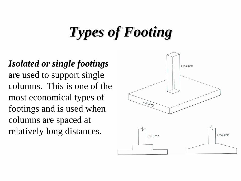
Isolated or single footings
are used to support single
columns. This is one of the
most economical types of
footings and is used when
columns are spaced at
relatively long distances.
Types of Footing
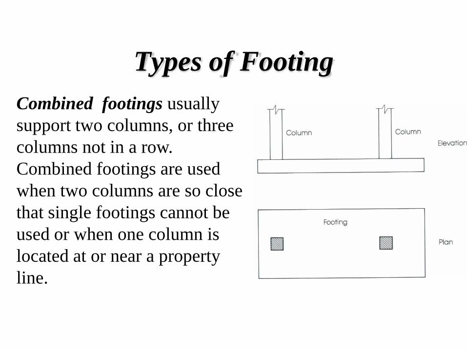
Combined footings usually
support two columns, or three
columns not in a row.
Combined footings are used
when two columns are so close
that single footings cannot be
used or when one column is
located at or near a property
line.
Types of Footing
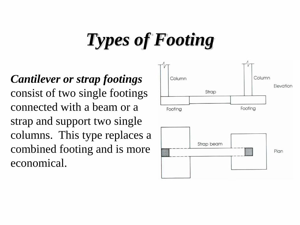
Cantilever or strap footings
consist of two single footings
connected with a beam or a
strap and support two single
columns. This type replaces a
combined footing and is more
economical.

Types of Footing
Continuous footings
support a row of three or
more columns. They have
limited width and continue
under all columns.
Types of Footing
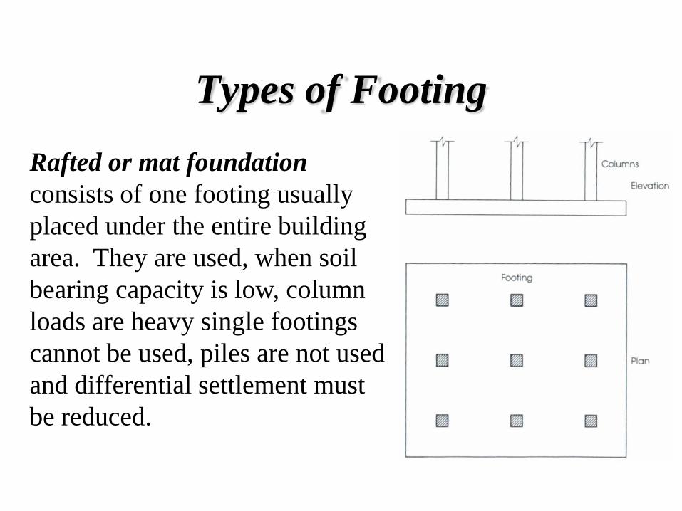
Rafted or mat foundation
consists of one footing usually
placed under the entire building
area. They are used, when soil
bearing capacity is low, column
loads are heavy single footings
cannot be used, piles are not used
and differential settlement must
be reduced.
Types of Footing
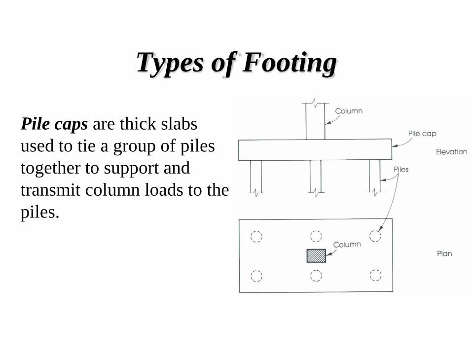
Pile caps are thick slabs
used to tie a group of piles
together to support and
transmit column loads to the
piles.
Distribution of Soil Pressure
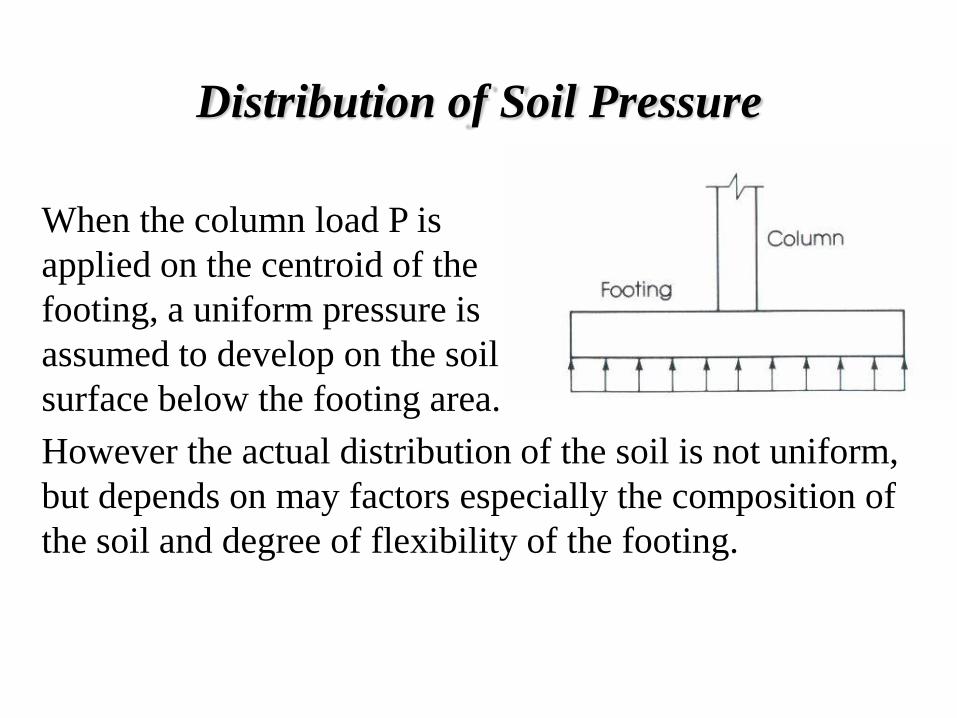
When the column load P is
applied on the centroid of the
footing, a uniform pressure is
assumed to develop on the soil
surface below the footing area.
However the actual distribution of the soil is not uniform,
but depends on may factors especially the composition of
the soil and degree of flexibility of the footing.

Distribution of Soil Pressure
Soil pressure distribution in
cohesionless soil.
Soil pressure distribution in
cohesive soil.

Design Considerations
Footings must be designed to carry the column loads
and transmit them to the soil safely while satisfying
code limitations.
The area of the footing based on the allowable
bearing soil capacity
Two-way shear or punch out shear.
One-way bearing
Bending moment and steel reinforcement
required
1.
2.
3.
4.
Design Considerations
Footings must be designed to carry the column loads
and transmit them to the soil safely while satisfying
code limitations.
Bearing capacity of columns at their base
Dowel requirements
Development length of bars
Differential settlement
1.
2.
3.
4.

Size of Footing
The area of footing can be determined from the actual
external loads such that the allowable soil pressure is
not exceeded.
pressure soil allowable
weight-self including load Total footing of Area
footing of area
uu
Pq
Strength design requirements
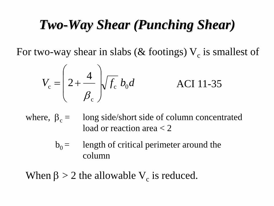
Two-Way Shear (Punching Shear)
For two-way shear in slabs (& footings) Vc is smallest of
long side/short side of column concentrated
load or reaction area < 2
length of critical perimeter around the
column
where, bc =
b0 =
ACI 11-35 dbfV 0c
c
c 4
2
b
When b > 2 the allowable Vc is reduced.
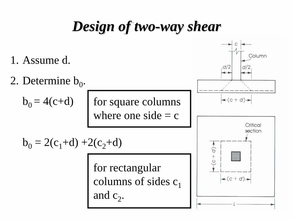
Design of two-way shear
Assume d.
Determine b0.
b0 = 4(c+d)
b0 = 2(c1+d) +2(c2+d)
1.
2.
for square columns
where one side = c
for rectangular
columns of sides c1
and c2.
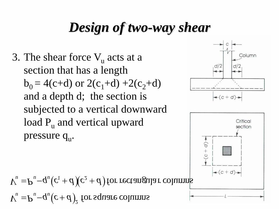
Design of two-way shear
The shear force Vu acts at a
section that has a length
b0 = 4(c+d) or 2(c1+d) +2(c2+d)
and a depth d; the section is
subjected to a vertical downward
load Pu and vertical upward
pressure qu.
3.
columnsr rectangulafor
columns squarefor
21uuu
2
uuu
dcdcqPV
dcqPV
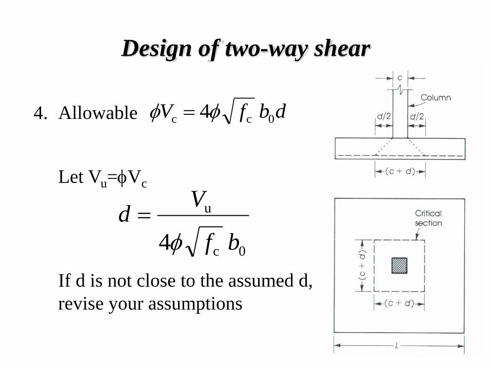
Design of two-way shear
Allowable
Let Vu=fVc
4. dbfV 0cc 4ff
0c
u
4 bf
Vd
f
If d is not close to the assumed d,
revise your assumptions
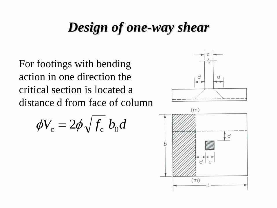
Design of one-way shear
For footings with bending
action in one direction the
critical section is located a
distance d from face of column
dbfV 0cc 2ff

Design of one-way shear
The ultimate shearing force at
section m-m can be calculated
d
cLbqV
22
uu
If no shear reinforcement is to be
used, then d can be checked
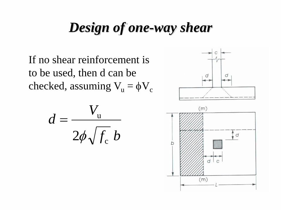
Design of one-way shear
bf
Vd
2 c
u
f
If no shear reinforcement is
to be used, then d can be
checked, assuming Vu = fVc
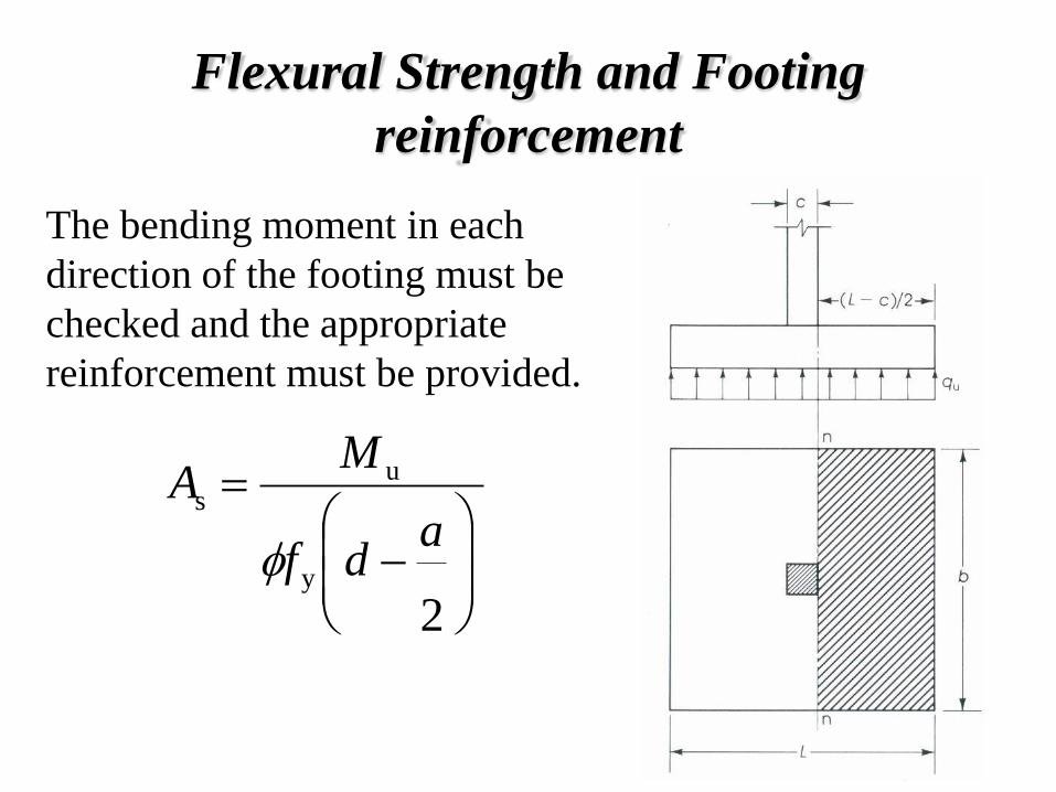
Flexural Strength and Footing
reinforcement
2y
us
a
df
MA
f
The bending moment in each
direction of the footing must be
checked and the appropriate
reinforcement must be provided.
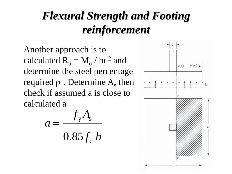
Flexural Strength and Footing
reinforcement
bf
Afa
85.0 c
sy
Another approach is to
calculated Ru = Mu / bd2 and
determine the steel percentage
required r . Determine As then
check if assumed a is close to
calculated a

Flexural Strength and Footing
reinforcement
The minimum steel percentage
required in flexural members is
200/fy with minimum area and
maximum spacing of steel bars
in the direction of bending shall
be as required for shrinkage
temperature reinforcement.

Flexural Strength and Footing
reinforcement
The reinforcement in one-way footings
and two-way footings must be
distributed across the entire width of
the footing.
1
2
directionshort in ent reinforcem Total
widthbandin ent Reinforcem
b
footing of sideshort
footing of side longbwhere

Bearing Capacity of Column at Base
The loads from the column act on the footing at the
base of the column, on an area equal to area of the
column cross-section. Compressive forces are
transferred to the footing directly by bearing on the
concrete. Tensile forces must be resisted by
reinforcement, neglecting any contribution by
concrete.
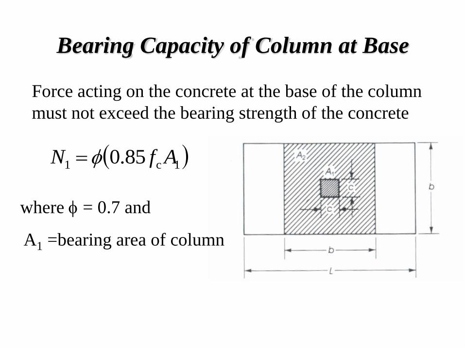
Bearing Capacity of Column at Base
Force acting on the concrete at the base of the column
must not exceed the bearing strength of the concrete
1c1 85.0 AfN f
where f = 0.7 and
A1 =bearing area of column

Bearing Capacity of Column at Base
The value of the bearing strength may be multiplied by a
factor for bearing on footing when the
supporting surface is wider on all sides than the loaded
area.
0.2/ 12 AA
The modified bearing
strength
1c2
121c2
85.02
/85.0
AfN
AAAfN
f
f

Dowels in Footings
A minimum steel ratio r = 0.005 of the column section
as compared to r = 0.01 as minimum reinforcement for
the column itself. The number of dowel bars needed is
four these may be placed at the four corners of the
column. The dowel bars are usually extended into the
footing, bent at the ends, and tied to the main footing
reinforcement. The dowel diameter shall not exceed
the diameter of the longitudinal bars in the column by
more than 0.15 in.
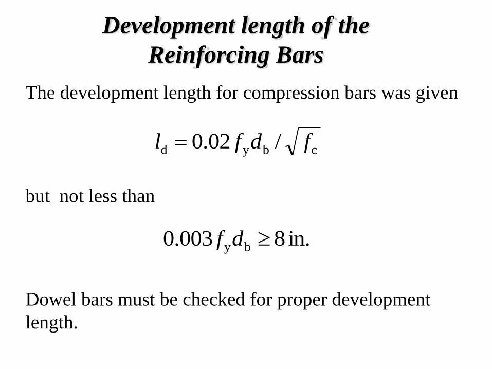
Development length of the
Reinforcing Bars
The development length for compression bars was given
but not less than
Dowel bars must be checked for proper development
length.
cbyd /02.0 fdfl
in. 8003.0 by df

Differential Settlement
Footing usually support the following loads:
Dead loads from the substructure and superstructure
Live load resulting from material or occupancy
Weight of material used in back filling
Wind loads
1.
2.
3.
4.
General Requirements for Footing Design
A site investigation is required to determine the
chemical and physical properties of the soil.
Determine the magnitude and distribution of
loads form the superstructure.
Establish the criteria and the tolerance for the
total and differential settlements of the structure.
1.
2.
3.

General Requirements for Footing Design
Determine the most suitable and economic type
of foundation.
Determine the depth of the footings below the
ground level and the method of excavation.
Establish the allowable bearing pressure to be
used in design.
4.
5.
6.

General Requirements for Footing Design
Determine the pressure distribution beneath the
footing based on its width
Perform a settlement analysis.
7.
8.