lecture 15 chapter 30 fall 2012 - university of alabama at
TRANSCRIPT

PH 222-2C Fall 2012
Induction and inductanceLecture 15
Chapter 30(Halliday/Resnick/Walker, Fundamentals of Physics 8th edition)
1

Chapter 30 Induction and Inductance
In this chapter we will study the following topics:
-Faraday’s law of induction -Lenz’s rule -Electric field induced by a changing magnetic field -Inductance and mutual inductance - RL circuits -Energy stored in a magnetic field
2

In a series of experiments, Michael Faraday in England and Joseph Henry in the U.S. were able to generate electric currents without the use of batteries. Below we describe some of
Faraday's Experiments
these experiments thathelped formulate what is known as "Faraday's lawof induction."
The circuit shown in the figure consists of a wire loop connected to a sensitiveammeter (known as a "galvanometer"). If we approach the loop with a permanent magnet we see a current being registered by the galvanometer. The results can be summarized as follows:
A current appears only if there is relative motion between the magnet and the loop. Faster motion results in a larger current. If
1.2.3. we reverse the direction of motion or the polarity of the magnet, the currentreverses sign and flows in the opposite direction. The current generated is known as " "; the emf that appearinduced current s is known as " "; the whole effect is called " "induced emf induction. 3

In the figure we show a second type of experimentin which current is induced in loop 2 when the switch S in loop 1 is either closed or opened. Whenthe current in loop 1 is constant no induced currentis observed in loop 2. The conclusion is that the magnetic field in an induction experiment can begenerated either by a permanent magnet or by anelectric current in a coil.
loop 1loop 2
Faraday summarized the results of his experiments in what is known as" "Faraday's law of induction.
An emf is induced in a loop when the number of magnetic field lines thatpass through the loop is changing.
Faraday's law is not an explanation of induction but merely a description of what induction is. It is one of the four " of electromagnetism,"all of which are statements of experimen
Maxwell's equationstal results. We have already encountered
Gauss' law for the electric field, and Ampere's law (in its incomplete form). 4

B
n̂
dA
The magnetic flux through a surface that bordersa loop is determined as follows:
Magnetic Flux Φ
1
B
We divide the surface that has the loop as its borderinto elements of area . dA.
For each element we calculate the magnetic flux through it: cos .ˆHere is the angle between the normal and the magnetic field vectors
at the position of the element.
We integrate
Bd BdA
n B
2.
3.
2: T m known as the Weber (symbol
all the terms. cos
We can express Faraday's law of induction in the followinWb).
g form:
B BdA B dA
SI magnetic flux unit
The magnitude of the emf induced in a conductive loop is equal to the rate at which the magnetic flux Φ through the loop changes with time.B
B B dA
Bddt
5

B
n̂
dA
cosB BdA B dA
Change the magnitude of within the loop. Change either the total area of the coil or
the portion of the area within the magnetic field.
Change the angl
BMethods for Changing Φ Through a Loop1.2.
3.
B
ˆe between and .
Problem 30-11cos cos
sin
22 sin 2
B
B
B n
NAB NabB td NabB tdtffNabB ft
An Example.
B
n̂
loop6

Bddt
We now concentrate on the negative sign in the equation that expresses Faraday's law.The direction of the flow of induced currentin a loop is accurately predicted by what is known as Lenz's
Lenz's Rule
rule.
An induced current has a direction such that the magnetic field due to the induced current opposes the change in the magnetic flux that induces the current.
Lenz's rule can be implemented using one of two methods:
In the figure we show a bar magnet approaching a loop. The induced current flowsin the direction indicated becaus
1. Opposition to pole movement
e this current generates an induced magnetic fieldthat has the field lines pointing from left to right. The loop is equivalent to a magnet whose north pole faces the corresponding north pole of the bar magnetapproaching the loop. The loop the approaching magnet and thus opposes the change in that generated the induced current.B
repels
7

N S
magnet motion
Bar magnet approaches the loop with the north pole facing the loop.
2. Opposition to flux changeExample :a
As the bar magnet approaches the loop, the magnetic field points toward the leftand its magnitude increases with time at the location of the loop. Thus the magnitudeof the loop magnetic flux alB
B
net
so increases. The induced current flows in the
(CCW) direction so that the induced magnetic field opposes
the magnetic field . The net field . The induced current i
i
B
B B B B
counterclockwise
is thus trying
to from increasing. Remember that it was the increase in that generated the induced current in the first place.
B B prevent
8

N S
magnet motion
Bar magnet moves away from the loop with north pole facing the loop.
2. Opposition to flux changeExample :b
As the bar magnet moves away from the loop, the magnetic field points toward the left and its magnitude decreases with time at the location of the loop. Thus the magnitude of the loop magnetic flu
B
net
x also decreases. The induced current flows in the (CW) direction so that the induced
magnetic field adds to the magnetic field . The net field . The induced current
B
i iB B B B B
clockwise
is thus trying to from decreasing. Remember that it was the decrease in that generated the induced current in the first place.
B
B
prevent
9

S N
magnet motion
Bar magnet approaches the loop with south pole facing the loop.
2. Opposition to flux changeExample :c
As the bar magnet approaches the loop, the magnetic field points toward the right and its magnitude increases with time at the location of the loop. Thus the magnitude of the loop magnetic flux B
B
net
also increases. The induced current
flows in the (CW) direction so that the induced magnetic field
opposes the magnetic field . The net field . The induced current is t
i
i
B
B B B B
clockwise
hus trying to from increasing. Remember that it was the increase in that generated the induced current in the first place.
B
B
prevent
10

S N
magnet motion
Bar magnet moves away from the loop with south pole facing the loop.
2. Opposition to flux changeExample :d
As the bar magnet moves away from the loop, the magnetic field points toward the right and its magnitude decreases with time at the location of the loop. Thus the magnitude of the loop magnetic fl
B
net
ux also decreases. The induced currentflows in the (CCW) direction so that the induced magnetic
field adds to the magnetic field . The net field . The induced
B
i iB B B B B
counterclockwise
Bcurrent is thus trying to from decreasing. Remember that it was the decrease in that generated the induced current in the first place. B
prevent
11

By Lenz's rule, the induced current always opposesthe external agent that produced the induced current.Thus the external agent must always on theloop-magnetic fie
Induction and Energy Transfers
do workld system. This work appears as
thermal energy that gets dissipated on the resistance of the loop wire.
Lenz's rule is actually a different formulation ofthe principle of energy conservation.Consi
R
der the loop of width shown in the figure. Part of the loop is located in a region where a uniform magnetic field exists. The loop is beingpulled outside the magnetic field region with constants
L
B
peed . The magnetic flux through the loop is. The flux decreases with time:
B
B
vBA BLx
d dx BLvBL BLv idt dt R R
12

2 2 2 22
th
2 3
The rate at which thermal energy is dissipated on is
( )
The magnetic forces on the wire sides are shown
in the figure. Forces and cancel each other:
Force
R
BLv B L vP i R RR R
F F
eq. 1
1 1
2 2
1
2 2 2
ext 1
, sin 90 ,
. The rate at which the external agent is
producing mechanical work is ( )
If we compare equations 1 and 2 we see that indeed the
BLvF iL B F iLB iLB LBR
B L vFR
B L vP FvR
eq. 2
mechanical work done by the external agent that movesthe loop is converted into thermal energy that appearson the loop wires.
13

We replace the wire loop in the previous example with a solid conducting plate and move the plate out of the magnetic field as shown in the figure.
The motion between the plate and indB
Eddy Currents
uces a
current in the conductor and we encounter an opposing force. With the plate, the free electrons do not followone path as in the case of the loop. Instead, the electronsswirl around the plate. These currents are known as " " As in the case of the wire loop, the netresult is that the mechanical energy that moves the plate is transformed into thermal energy that heats up
eddy currents.
the plate.
14
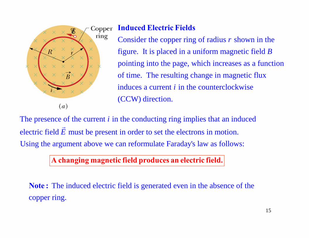
Consider the copper ring of radius shown in thefigure. It is placed in a uniform magnetic field pointing into the page, which increases as a function of time. The resulting
rB
Induced Electric Fields
change in magnetic fluxinduces a current in the counterclockwise(CCW) direction.
i
The presence of the current in the conducting ring implies that an induced
electric field must be present in order to set the electrons in motion.Using the argument above we can reformulate Farada
i
E
y's law as follows:
A changing magnetic field produces an electric field.
The induced electric field is generated even in the absence of the copper ring. Note :
15

Consider the circular closed path of radius shown in the figure to the left. The picture is the same as thaton the previous page except that the copper ring has been removed. The path is now an a
r
bstract line.The emf along the path is given by the equation
( )
The emf is also given by Faraday's law:
( ). If we compare eq. 1 with eq. 2
we get:
B
E d
dE d
s
ddt
s
eq. 1
eq. 2
2 2
2
cos 0
22
.
2
BB
B
E ds Eds E ds rE
d dBr B rdt dt
dBrE rd
dt
r dBEdtt
16

0
Consider a solenoid of length that has loops of
area each, and windings per unit length. A current
flows through the solenoid and generates a uniform magnetic field in
NNA n
iB ni
Inductance
side the solenoid.The solenoid magnetic flux is .B NBA
B
20The total number of turns . The result we got for the
special case of the solenoid is true for any inductor: . Here is a constant known as the of the solenoi
B
B
N n n A i
Li L
inductance
220
0
d. The inductance depends on the geometry of the particular inductor.
For the solenoid, .B n AiL n Ai i
Inductance of the Solenoid
20 L n A
17

loop 1loop 2In the picture to the right we
already have seen how a changein the current of loop 1 results in a change in the flux through loop 2, and thus creates an induced emf in loop 2.
Self - Induction
If we change the current through an inductor this causesa change in the magnetic flux through the inductor
according to the equation . Using Faraday's
law we can determine the resu
B
B
Lid diLdt dt
the henry (symbol: H)An inductor has inductance 1 H if a current change of 1 A/s results in a self
lting emf known as
-induced emf o
f
emf:
1 V
.
.
Bd diLdt dt
L
SI unit for :
self - induc
L
ed
diLdt
18

Consider the circuit in the upper figure with the switchS in the middle position. At 0 the switch is thrownin position and the equivalent circuit is shown inthe lower figure. It cont
ta
RL Circuits
ains a battery with emf , connected in series to a resistor and an inductor (thus the name " circuit"). Our objective is to calculate the current as a function of time . We write Kirchhoff'
R LRL
i t
s loop rule starting at point and moving around the loop in the clockwise direction:
0 diL iR
x
diiR Lt dd t
/
The initial condition for this problem is (0) 0. The solution of the differentialequation that satisfies the initial condition is
The constant is known as the "( ) 1 .t Li t eR R
i
time constant " of
the circuit. RL
/( ) 1 ti t eR
L
R
19

/
/
/
( ) 1 Here .
The voltage across the resistor 1 .
The voltage across the inductor .
The solution gives 0 at 0 as required by the initial conditi
t
tR
tL
Li t eR R
V iR e
diV L edt
i t
on. The solution gives ( ) / .The circuit time constant / tells us how fastthe current approaches its terminal value: ( ) 0.632 /
( 3 ) 0.950 /
( 5 ) 0.993 /If we wait only
i RL R
i t R
i t R
i t R
a few time
the current, for all
practical purposes, has reached its terminal value / . R constants
20

We have seen that energy can be stored in the electric fieldof a capacitor. In a similar fashion, energy can be stored inthe magnetic field of an inductor. Consider
Energy Stored in a Magnetic Field
the circuitshown in the figure. Kirchhoff's loop rule gives
2
2
. If we multiply both sides of the equation we get: .
The term describes the rate at which the battery delivers energy to the circuit.The term is the rate at which t
di diL iR i Li i Rdt dt
ii R
hermal energy is produced on the resistor.
Using energy conservation we conclude that the term is the rate at which
energy is stored in the inductor: . We integrate
both
BB
diLidt
dU diLi dU Lididt dt
2 2
sides of this equation: .2 2
ii
oB
o
L i LiU Li di
2
2B
LiU
21

B
0
Consider the solenoid of length and loop area that has windings per unit length. The solenoidcarries a current that generates a uniform magnetic field
An
iB ni
Energy Density of a Magnetic Field
inside the solenoid. The magnetic fieldoutside the solenoid is approximately zero.
2 22 01The energy stored by the inductor is equal to .
2 2This energy is stored in the empty space where the magnetic field is present.
We define as energy density where is the volume
B
BB
n A iU Li
Uu VV
2 2 2 2 2 2 2 20 0 0
0 0
inside
the solenoid. The density .2 2 2 2
This result, even though it was derived for the special case of a uniformmagnetic field, holds true in general.
Bn A i n i n i Bu
A
2
0
2BBu
22

N2N1 Consider two inductors
that are placed close enough so that the magnetic field of onecan influence the other.
Mutual Induction
1 1
2 21 1
1
In fig. we have a current in inductor 1. That creates a magnetic field in the vicinity of inductor 2. As a result, we have a magnetic flux through inductor 2. If current varies w
a i BM i
i
2 12 21 21
ith time, then we have a time-varying flux through inductor 2 and therefore an induced emf across it:
. is a constant that depends on the geometry
of the two inductors as we
d diM Mdt dt
ll as on their relative position.
12 21
diMdt
23

N2N1
2 2
1 12 2
2
In fig. we have a current in inductor 2. That creates a magnetic field in the vicinity of inductor 1. As a result, we have a magnetic flux through inductor 1. If current varies w
b i BM i
i
1 21 12 12
ith time, then we have a time-varying flux through inductor 1 and therefore an induced emf across it:
. is a constant that depends on the geometry
of the two inductors as w
d diM Mdt dt
ell as on their relative position.
21 12
diMdt
24

N2N1
12 21
diMdt
21 12
diMdt
12 21 12 21It can be shown that the constants and are equal: .The constant is known as the " " between the two coils.Mutual inductance is a constant that depends on the geomet
M M M M MM
mutual inductance
thry
e hof the
enry ( two
inductors as well as on their relative position. The expressions for the induced emfs across the two inductors be
)ome:
Hc
The SI unit for :M
21 diM
dt 1
2diMdt
1 2Mi 2 1Mi 25