lecture 13 gas compression and transport r0 - fitstaff.fit.ac.cy/eng.ap/fall2016/moe506/lecture 13...
TRANSCRIPT
12/5/2016
1
Energoil
Consulting
Lecture 13
Gas Compression and Transport
© Dr. Richard J Barnes 2015 Slide 1
Energoil
Consulting
Pipeline Characteristics
© Dr. Richard J Barnes 2015 Slide 2

12/5/2016
2
Energoil
ConsultingErosional Velocity
• Fluid is continuously flowing past the pipe wall.
• Above a certain velocity, the fluid wears, or
erodes, the pipeline.
• Similar to a high-pressure water hose.
• The velocity that erosion starts is the erosional
velocity.
• Normally operate below the erosional velocity.
© Dr. Richard J Barnes 2015 Slide 3
Energoil
ConsultingEmpirical Erosional Velocity
Erosional velocity,
where V = Erosional velocity, ft/s
C = 100 for continuous liquid flow with
solids.
= 125 for intermittent flow
= 200 in corrosion resistant pipelines
ρ = Fluid density, lb/ft3.
=C
Vρ
© Copyright Dr. Richard J Barnes 2015 Slide 4
12/5/2016
3
Energoil
ConsultingTypes of Material
• Carbon steel;
• Duplex (stainless) steel;
• GRP (Glass reinforced plastic);
• Polyethylene (for water and low pressure gas
lines).
© Dr. Richard J Barnes 2015 Slide 5
Energoil
ConsultingPipe Lining
• Applied internally;
• Used for corrosion prevention or to reduce
friction;
• Must be continuous for corrosion protection;
• Can be alloy, epoxy or rubber;
• Polyethylene used on gas mains.
© Dr. Richard J Barnes 2015 Slide 6

12/5/2016
4
Energoil
ConsultingPipe Coating
• Applied externally.
• For corrosion prevention.
• Thermal insulation.
• Weight coating.
© Dr. Richard J Barnes 2015 Slide 7
Energoil
ConsultingExternal Coating
• Applied in factory;
• Joints coated in field;
• Damage protection
during installation;
• Protects pipe from
corrosion;
• Fusion Bonded Epoxy;
• 3 layer polyethylene.
Source: www.sakhalinenergy.com
© Dr. Richard J Barnes 2015 Slide 8

12/5/2016
5
Energoil
ConsultingHeat Tracing
• Used to reduce heat
loss from fluid;
• Often used to keep
viscous fluids warm;
• Expensive to install and
maintain;
• Heating medium
electricity, steam, hot
oil or heat transfer fluid.Source: www.tycothermal.com
© Dr. Richard J Barnes 2015 Slide 9
Energoil
Consulting
Pressure Containment
© Dr. Richard J Barnes 2015 Slide 10

12/5/2016
6
Energoil
ConsultingDesign Issues
• Pipe stability:
– On seabed;
– Mud slides, slopes, earthquakes.
• Stress:
– Hydrostatic testing;
– Free span stress;
– Installation stress;
– Operating and testing;
– Expansion.© Dr. Richard J Barnes 2015 Slide 11
Energoil
ConsultingFailure Modes
• Buckling
• Upheaval buckling;
• Erosion and corrosion;
• Fatigue;
• Collapse.
© Dr. Richard J Barnes 2015 Slide 12

12/5/2016
7
Energoil
ConsultingPressure Design
• Design to withstand the internal pressure in the
pipe.
• Withstand stress from installation process.
• Withstand external hydrostatic pressure.
• Allowance for corrosion.
• Allowance must also be made for dimensional
tolerance.
© Dr. Richard J Barnes 2015 Slide 13
Energoil
ConsultingWall Thickness Calculation
Minimum wall thickness, tm mm.
tm = wall thickness, mm
P = Design pressure, kPa (g)
dO= Outside diameter, mm
S = Minimum yield strength, kPa
F = Construction type design factor
E = Longitudinal joint factor
T = Temperature derating
(Temperature < 120 °C, T =1.0)
tc = Corrosion allowance, mm
2
Om c
Pdt t
SFET= +
© Dr. Richard J Barnes 2015 Slide 14
12/5/2016
8
Energoil
ConsultingWall Thicknesses
• tm minimum wall thickness:
Wall required be code calculation to contain
the internal pressure.
• tc corrosion allowance:
Thickness above tm that could corrode and not
affect the operating pressure.
• Standard manufactured wall thickness.
© Dr. Richard J Barnes 2015 Slide 15
Energoil
ConsultingExample Calculation (1)
• Design pressure: 30 barg, 3,000 kPa (g)
• Pipe outside diameter: 16”, 406.4 mm
• Minimum yield strength: 241,000 kPa
• Construction type design factor: 0.72
• Longitudinal joint factor: 1.0
• Temperature derating factor: 1.0
• Corrosion allowance: 3 mm
© Dr. Richard J Barnes 2015 Slide 16

12/5/2016
9
Energoil
ConsultingExample Calculation (2)
Minimum wall thickness, tm mm.
2
Om c
Pdt t
SFET= +
© Dr. Richard J Barnes 2015 Slide 17
3,000 406.43.0
2 241,000 0.72 1.0 1.0=
×+
× × × ×mt
6.51=mt mm
Energoil
ConsultingUse of Flanges
• Flanges used to
provide joint in the
line;
• Used to connect
valves, filters, pumps
and compressors;
• Can be a source of
leaks.Source: Richard J. Barnes
© Dr. Richard J Barnes 2015 Slide 18
12/5/2016
10
Energoil
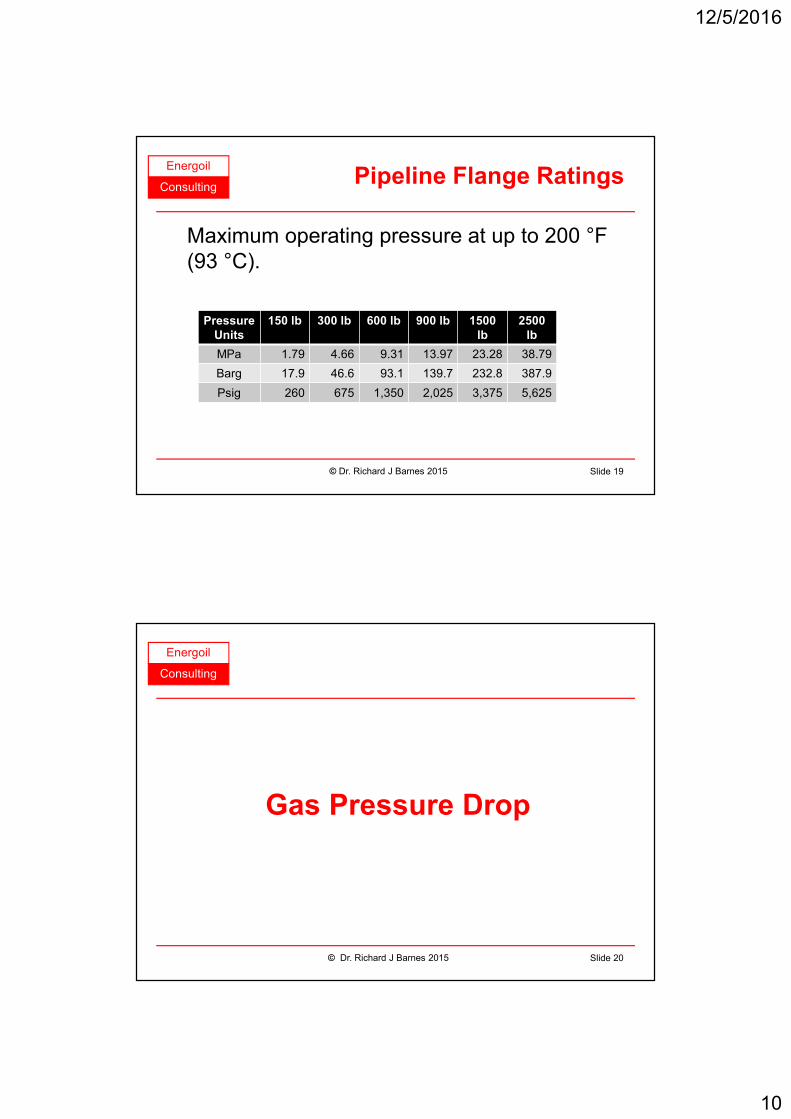
ConsultingPipeline Flange Ratings
Maximum operating pressure at up to 200 °F
(93 °C).
© Dr. Richard J Barnes 2015 Slide 19
Pressure
Units
150 lb 300 lb 600 lb 900 lb 1500
lb
2500
lb
MPa 1.79 4.66 9.31 13.97 23.28 38.79
Barg 17.9 46.6 93.1 139.7 232.8 387.9
Psig 260 675 1,350 2,025 3,375 5,625
Energoil
Consulting
Gas Pressure Drop
© Dr. Richard J Barnes 2015 Slide 20

12/5/2016
11
Energoil
ConsultingImportance of Pressure Drop
• High pressure drop leads to larger gas
compressors;
• Operating costs will be higher;
• Larger proportion of gas from pipeline could
be burnt as fuel.
© Dr. Richard J Barnes 2015 Slide 21
Energoil
ConsultingCalculation Sequence
• Divide pipeline into sections.
• Calculate physical properties.
• Calculate overall pressure drop.
• Pressure drop must be calculated over short
sections because the gas density is not
constant.
© Dr. Richard J Barnes 2015 Slide 22

12/5/2016
12
Energoil
ConsultingPressure Drop Factors
• Gas properties.
• Pipeline diameter.
• Flowrate.
• Temperature.
• Velocity.
• Pressure.
• Internal roughness.
© Dr. Richard J Barnes 2015 Slide 23
Energoil
ConsultingCompressibility Factor
• The compressibility factor, Z, is a
dimensionless number that represents a gas's
deviation from ideal gas behaviour.
• It can be estimated from other physical
properties.
© Dr. Richard J Barnes 2015 Slide 24

12/5/2016
13
Energoil
ConsultingNomenclature
Q Flowrate at base conditions, m3/day
Ts Standard temperature (288.9 °K)
Ps Standard pressure (101.56 kPa)
E Pipeline efficiency, use 1.0
d Pipe internal diameter, mm
ε Pipe roughness, mm
P1 Inlet pressure, kPa
P2 Outlet pressure, kPa
γ Gas specific gravity
L Pipeline length, m
T Average flowing temperature, °K
Z Compressibility factor
© Dr. Richard J Barnes 2015 Slide 25
Energoil
ConsultingAGA Equation
• Used for turbulent flow.
0.52 2
2.51 210
3.70.018 4 logS
S m avg avg
T P PdQ E d
P L T Zε γ
− =
22
2 1 2
5
10
3086
3.74 logS
S
Q LTZP P
T dE d
P
γ
ε
= −
© Dr. Richard J Barnes 2015 Slide 26
12/5/2016
14
Energoil
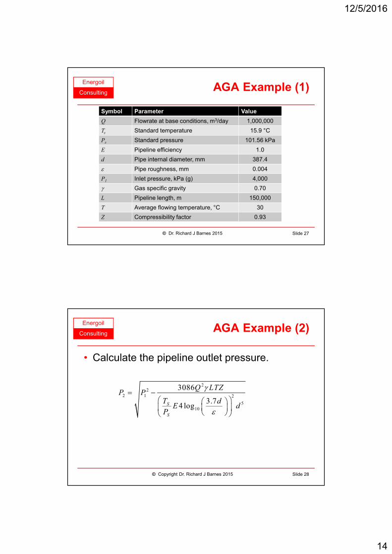
ConsultingAGA Example (1)
© Dr. Richard J Barnes 2015 Slide 27
Symbol Parameter Value
Q Flowrate at base conditions, m3/day 1,000,000
Ts Standard temperature 15.9 °C
Ps Standard pressure 101.56 kPa
E Pipeline efficiency 1.0
d Pipe internal diameter, mm 387.4
ε Pipe roughness, mm 0.004
P1 Inlet pressure, kPa (g) 4,000
γ Gas specific gravity 0.70
L Pipeline length, m 150,000
T Average flowing temperature, °C 30
Z Compressibility factor 0.93
Energoil
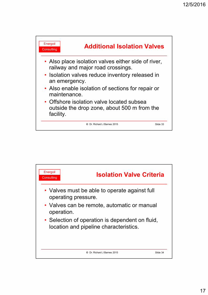
ConsultingAGA Example (2)
• Calculate the pipeline outlet pressure.
22
2 1 2
5
10
3086
3.74 logS
S
Q LTZP P
T dE d
P
γ
ε
= −
© Copyright Dr. Richard J Barnes 2015 Slide 28

12/5/2016
15
Energoil
ConsultingAGA Example (3)
22
2 1 2
5
10
3086
3.74 logS
S
Q LTZP P
T dE d
P
γ
ε
= −
© Dr. Richard J Barnes 2015 Slide 29
22
2 2
5
10
3086 1,000,000 0.70 160,000 303 0.934,101.325
15.9 273 3.7 387.41.0 4 log 387.4
101.56 0.004
× × × × ×= −
+ × ×
P
P2 = 3,768 kPa or 3,667 kPa (g)
Energoil
Consulting
Design Safety
© Dr. Richard J Barnes 2015 Slide 30

12/5/2016
16
Energoil
ConsultingDesign Pressure
• Design pressure is maximum pressure to
which the pipeline should ever be subjected.
• Pipeline must be protected from pressures
above the design pressure.
• Design pressure is normally 110% of
maximum operating pressure.
© Dr. Richard J Barnes 2015 Slide 31
Energoil
ConsultingDesign Temperature
• Design temperature is the maximum
temperature to which a pipeline should ever
be exposed.
• Limited by allowable stress of pipe material,
limit of coating material or limit to amount of
expansion or contraction.
• Ideally at least 25 °C above maximum
operating temperature.
© Dr. Richard J Barnes 2015 Slide 32
12/5/2016
17
Energoil
ConsultingAdditional Isolation Valves
• Also place isolation valves either side of river, railway and major road crossings.
• Isolation valves reduce inventory released in an emergency.
• Also enable isolation of sections for repair or maintenance.
• Offshore isolation valve located subsea outside the drop zone, about 500 m from the facility.
© Dr. Richard J Barnes 2015 Slide 33
Energoil
ConsultingIsolation Valve Criteria
• Valves must be able to operate against full
operating pressure.
• Valves can be remote, automatic or manual
operation.
• Selection of operation is dependent on fluid,
location and pipeline characteristics.
© Dr. Richard J Barnes 2015 Slide 34

12/5/2016
18
Energoil
ConsultingPipe Rupture or Emergency
• Loss of pressure can be caused by a leak due
to corrosion or mechanical damage.
• Loss of pressure should be detected
automatically.
• Pipeline shutdown and isolation should be
automatic.
• In an emergency the operator must be able to
shut down and isolate the pipeline remotely.
© Dr. Richard J Barnes 2015 Slide 35
Energoil
ConsultingLeak Detection
• Automatic system for detecting leaks.
• Based on accurate measurement of fluid
entering and leaving section.
• Leaks can be very small.
• Trend and statistical analysis can improve
accuracy.
© Dr. Richard J Barnes 2015 Slide 36
12/5/2016
19
Energoil
Consulting
Onshore Pipelay
© Dr. Richard J Barnes 2015 Slide 37
Energoil
ConsultingObstructions
• Road, rail or river;
• Ravines or cliffs;
• Seismically active areas
• Other pipelines;
• Underground utilities;
• Overhead utilities;
• Ground conditions.
© Dr. Richard J Barnes 2015 Slide 38

12/5/2016
20
Energoil
ConsultingSurvey Route
• Lays out the route of the
pipeline;
• Defines width of access
• Area classification;
• Soil types and gradients;
• Identify and locate
obstructions;
• Locate features.Source: www.naturalgas.org
© Dr. Richard J Barnes 2015 Slide 39
Energoil
ConsultingDigging Trench
• Trench cut to bury
pipe about 1 m;
• Protects pipeline;
• Allows vehicles and
animals to cross;
• Provides some
thermal insulation.Source: Essochad.com
© Dr. Richard J Barnes 2015 Slide 40
12/5/2016
21
Energoil
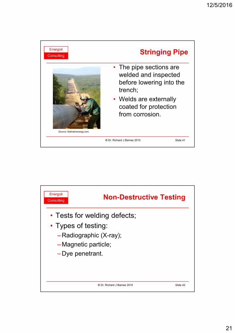
ConsultingStringing Pipe
• The pipe sections are
welded and inspected
before lowering into the
trench;
• Welds are externally
coated for protection
from corrosion.
Source: Sakhalinenergy.com
© Dr. Richard J Barnes 2015 Slide 41
Energoil
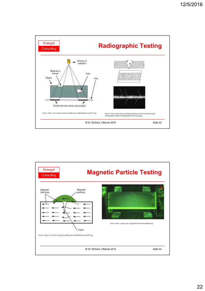
ConsultingNon-Destructive Testing
• Tests for welding defects;
• Types of testing:
– Radiographic (X-ray);
– Magnetic particle;
– Dye penetrant.
© Dr. Richard J Barnes 2015 Slide 42
12/5/2016
22
Energoil
ConsultingRadiographic Testing
© Dr. Richard J Barnes 2015 Slide 43
Source: https://www.nde-ed.org/GeneralResources/MethodSummary/RT1.jpg Source: http://www.ndt-ed.org/EducationResources/CommunityCollege/
Radiography/Graphics/RadiographInterp/Porosity.jpg
Energoil
ConsultingMagnetic Particle Testing
© Dr. Richard J Barnes 2015 Slide 44
Source: https://www.nde-ed.org/GeneralResources/MethodSummary/MT1.jpg
Source: http://i.ytimg.com/vi/qpgcD5k1494/maxresdefault.jpg

12/5/2016
23
Energoil
ConsultingDye Penetrant Testing
© Dr. Richard J Barnes 2015 Slide 45
Source: http://img.tjskl.org.cn/pic/z187cc82-200x200-1/
visible_dye_penetrant_inspection_materials.jpg
Source: https://www.asnt.org/~/media/Images/
About/IntroductionToNDT/fig7.ashx
Source: http://www.sentinelltd.co.nz/SiteAssets/ndt/defect.jpg
Energoil
ConsultingLowering into Trench
• After welding and
testing the pipe is
lowered into the
trench;
• The pipe is then
covered with backfill
material and is ready
for testing.Source: Sakhalinenergy.com
© Dr. Richard J Barnes 2015 Slide 46

12/5/2016
24
Energoil
ConsultingReinstatement
• The land is restored as
much as possible to its
original state;
• Pipe is normally 1 m
below surface;
• Can be used for
farming or grazing.Source: www.mcos.ie
© Dr. Richard J Barnes 2015 Slide 47
Energoil
ConsultingAlternative to Burial
• Avoids upheaval in
permafrost areas;
• Used through swamp
areas and seismically
active areas;
• Allows animals to cross
under pipe;
• Bridges or
underpasses for traffic.
Source: www.doty.org
© Dr. Richard J Barnes 2015 Slide 48

12/5/2016
25
Energoil
ConsultingRiver Crossing
• Can be crossed by damming;
• By new or existing road or rail bridge.
Source: www.waterstructures.com
Source: www.nwf.org
© Dr. Richard J Barnes 2015 Slide 49
Energoil
ConsultingDirectional Drilling
• Enables pipeline to be
installed under roads,
railways and rivers
without disturbance
• Requires acceptable soil
conditions - no rocks or
boulders;
• Tunnelling for rocky
conditions.
Source: www.arizonapipeline.com
© Dr. Richard J Barnes 2015 Slide 50

12/5/2016
26
Energoil
Consulting
Offshore Pipelay
© Dr. Richard J Barnes 2015 Slide 51
Energoil
ConsultingMain Methods
• Lay methods:
– Pipelay barge;
– Reel lay;
– Towed lay.
• Vessel types:
– Semisubmersible;
– Shipshape;
– Shallow draft barge.Source: www.imca-int.com
Pipelay Methods
© Dr. Richard J Barnes 2015 Slide 52
12/5/2016
27
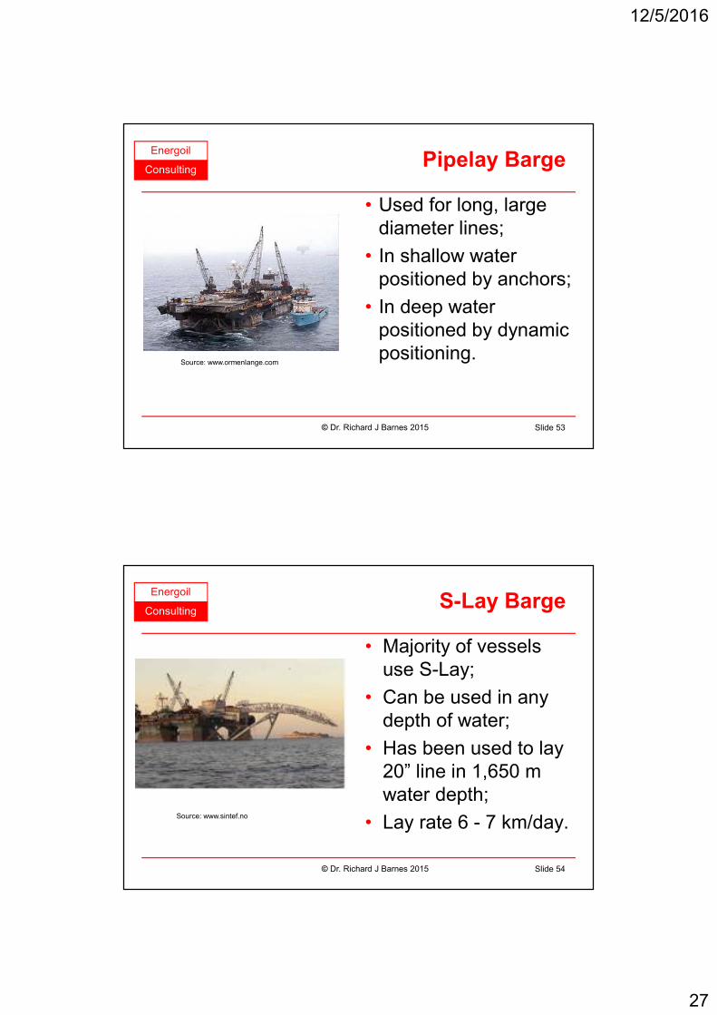
Energoil
ConsultingPipelay Barge
• Used for long, large
diameter lines;
• In shallow water
positioned by anchors;
• In deep water
positioned by dynamic
positioning.Source: www.ormenlange.com
Pipelay Barge
© Dr. Richard J Barnes 2015 Slide 53
Energoil
ConsultingS-Lay
• Majority of vessels
use S-Lay;
• Can be used in any
depth of water;
• Has been used to lay
20” line in 1,650 m
water depth;
• Lay rate 6 - 7 km/day.Source: www.sintef.no
S-Lay Barge
© Dr. Richard J Barnes 2015 Slide 54
12/5/2016
28
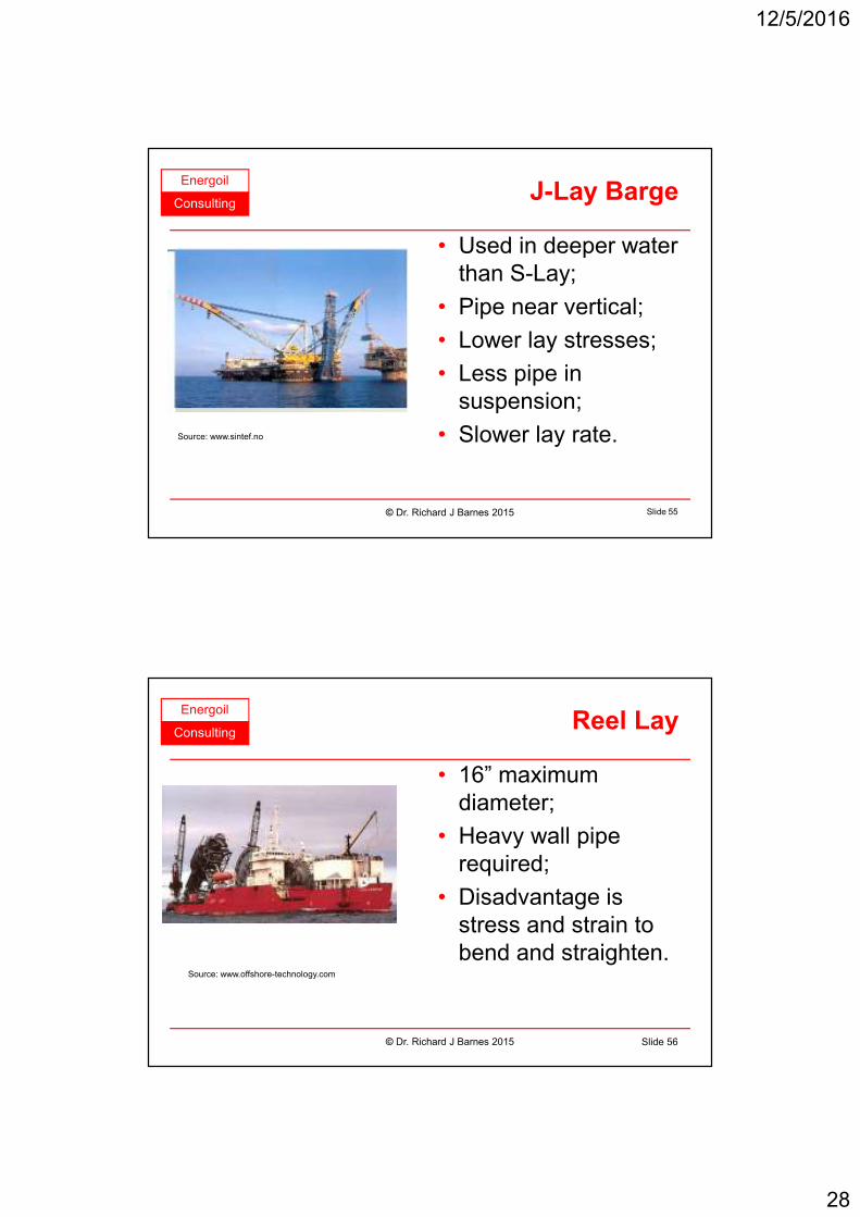
Energoil
ConsultingJ-Lay
• Used in deeper water
than S-Lay;
• Pipe near vertical;
• Lower lay stresses;
• Less pipe in
suspension;
• Slower lay rate.Source: www.sintef.no
J-Lay Barge
© Dr. Richard J Barnes 2015 Slide 55
Energoil
ConsultingReel Lay
• 16” maximum
diameter;
• Heavy wall pipe
required;
• Disadvantage is
stress and strain to
bend and straighten.Source: www.offshore-technology.com
Reel Lay
© Dr. Richard J Barnes 2015 Slide 56
12/5/2016
29
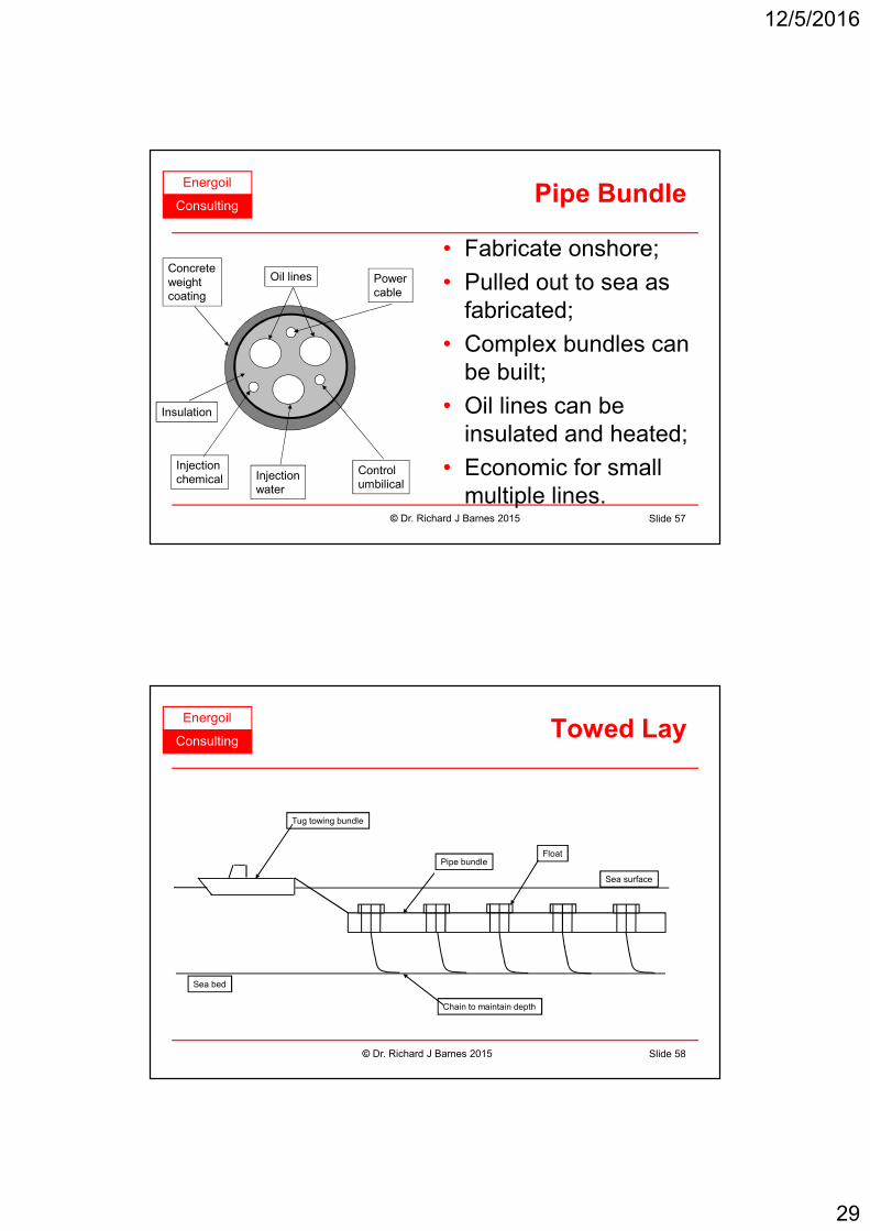
Energoil
ConsultingPipe Bundle
• Fabricate onshore;
• Pulled out to sea as
fabricated;
• Complex bundles can
be built;
• Oil lines can be
insulated and heated;
• Economic for small
multiple lines.
Oil lines
Insulation
Power
cable
Control
umbilicalInjection
water
Injection
chemical
Concrete
weight
coating
Pipe Bundle
© Dr. Richard J Barnes 2015 Slide 57
Energoil
ConsultingTowed Lay
Tug towing bundle
Chain to maintain depth
Pipe bundleFloat
Sea surface
Sea bed
© Dr. Richard J Barnes 2015 Slide 58
12/5/2016
30
Energoil
Consulting
Pigging
© Dr. Richard J Barnes 2015 Slide 59
Energoil
ConsultingPigging
• Pigging is the insertion of a device into a
pipeline and displacing it along the full length
of the pipeline to clean, separate or inspect
the line.
© Dr. Richard J Barnes 2015 Slide 60

12/5/2016
31
Energoil
ConsultingReasons for Pigging
• To clean the line of debris or wax.
• To distribute a protective chemical.
• To separate different products.
• To displace one fluid with another.
• To inspect the pipeline internally.
• Inspect pipewall thickness or ovality.
© Dr. Richard J Barnes 2015 Slide 61
Energoil
ConsultingTypes of Pigs
• Foam or cup pigs to
remove soft deposits.
• Brush pigs for more
severe cleaning.
• Scraper pigs to
remove wax.
• Also removes debris
and water pockets.Source: Pipeline Engineering and Apache Pipeline Products
© Dr. Richard J Barnes 2015 Slide 62
12/5/2016
32
Energoil
ConsultingInspecting the Pipeline
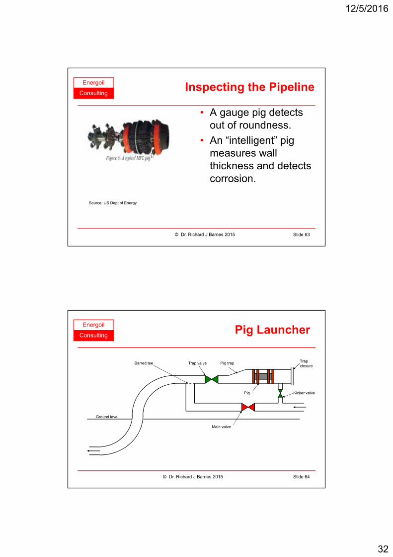
• A gauge pig detects
out of roundness.
• An “intelligent” pig
measures wall
thickness and detects
corrosion.
Source: US Dept of Energy
© Dr. Richard J Barnes 2015 Slide 63
Energoil
ConsultingPig Launcher
Pig trapTrap valveBarred tee
Pig Kicker valve
Trap
closure
Main valve
Ground level
© Dr. Richard J Barnes 2015 Slide 64
12/5/2016
33
Energoil
ConsultingPig Receiver
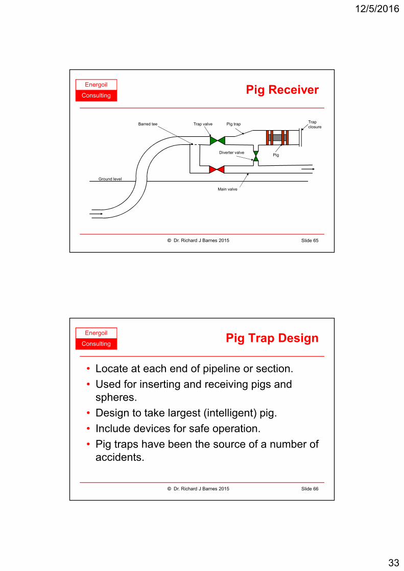
Pig trapTrap valveBarred tee
PigDiverter valve
Trap
closure
Main valve
Ground level
© Dr. Richard J Barnes 2015 Slide 65
Energoil
ConsultingPig Trap Design
• Locate at each end of pipeline or section.
• Used for inserting and receiving pigs and
spheres.
• Design to take largest (intelligent) pig.
• Include devices for safe operation.
• Pig traps have been the source of a number of
accidents.
© Dr. Richard J Barnes 2015 Slide 66
12/5/2016
34
Energoil
Consulting
Pipeline Protection
© Dr. Richard J Barnes 2015 Slide 67
Energoil
ConsultingInternal Corrosion Protection
• Regular fluid quality monitoring.
• Add corrosion inhibitor for protection.
• Avoid letting water accumulate.
• Maintain flow to avoid stagnant areas.
• Consider regular pigging.
• Installation of corrosion coupons.
• Avoid dead-legs in pipeline.
• Perform baseline survey.
© Dr. Richard J Barnes 2015 Slide 68

12/5/2016
35
Energoil
ConsultingExternal Corrosion Protection
• Regularly inspect right of way.
• Correctly applied external pipe wrap applied at
construction.
• Cathodic protection.
• Fusion bonded epoxy coating (FBE).
• 3 layer polyethylene pipe wrap.
© Dr. Richard J Barnes 2015 Slide 69
Energoil
ConsultingCorrosion Mechanism
• Corrosion cell current leaves at anode returns at
cathode.
• Soil conducts current externally.
• Pipe corroded at anode.
Anode Site Cathode Site
Electrolyte
Electrons
Pit Corrosion
Steel Pipe
Corrosion Current Corrosion Current
e e
+-
© Dr. Richard J Barnes 2015 Slide 70

12/5/2016
36
Energoil
ConsultingGalvanic Anode System
• Mainly used offshore;
• Pipe is connected to
magnesium anodes at
60 - 100 m intervals;
• Magnesium corrodes
in preference to steel;
• Anodes sized to last
the life of the pipeline.
Current flowing
through seawater
Insulated wire connecting
cathode to anode
Surface of sea
Magnesium ANODE
Higher potential than steel
Steel CATHODE
protected by anode
© Dr. Richard J Barnes 2015 Slide 71
Energoil
ConsultingPipeline Sacrificial Anodes
• Anodes strapped to
pipe;
• Current generated
monitored to check
performance and
detect high currents
© Dr. Richard J Barnes 2015 Slide 72
Source: http://www.stoprust.com/img/18pic3.jpg

12/5/2016
37
Energoil
ConsultingPlatform Sacrificial Anodes
• Anodes also used on
offshore steel jackets;
• Anode is made of
aluminium,
magnesium or an
alloy;
• Anodes inspected
regularly and replaced
when consumed.
© Dr. Richard J Barnes 2015 Slide 73
Source: http://www.hera.org.nz/images/
structural_systems/Anodes-on-jacket.jpg
Energoil
ConsultingImpressed Current System
• Electrical power
source opposes
corrosion cell.
• Anode bed and
equipment spaced
every 15 to 30 km.
• Anode corrodes
preferentially.Current flowing
through moist soil
Surface of earth
Cast iron ANODE
Dissipates impressed current
Battery, solar cell
or DC source
© Dr. Richard J Barnes 2015 Slide 74
12/5/2016
38
Energoil
Consulting
Compressor Stations
© Dr. Richard J Barnes 2015 Slide 75
Energoil
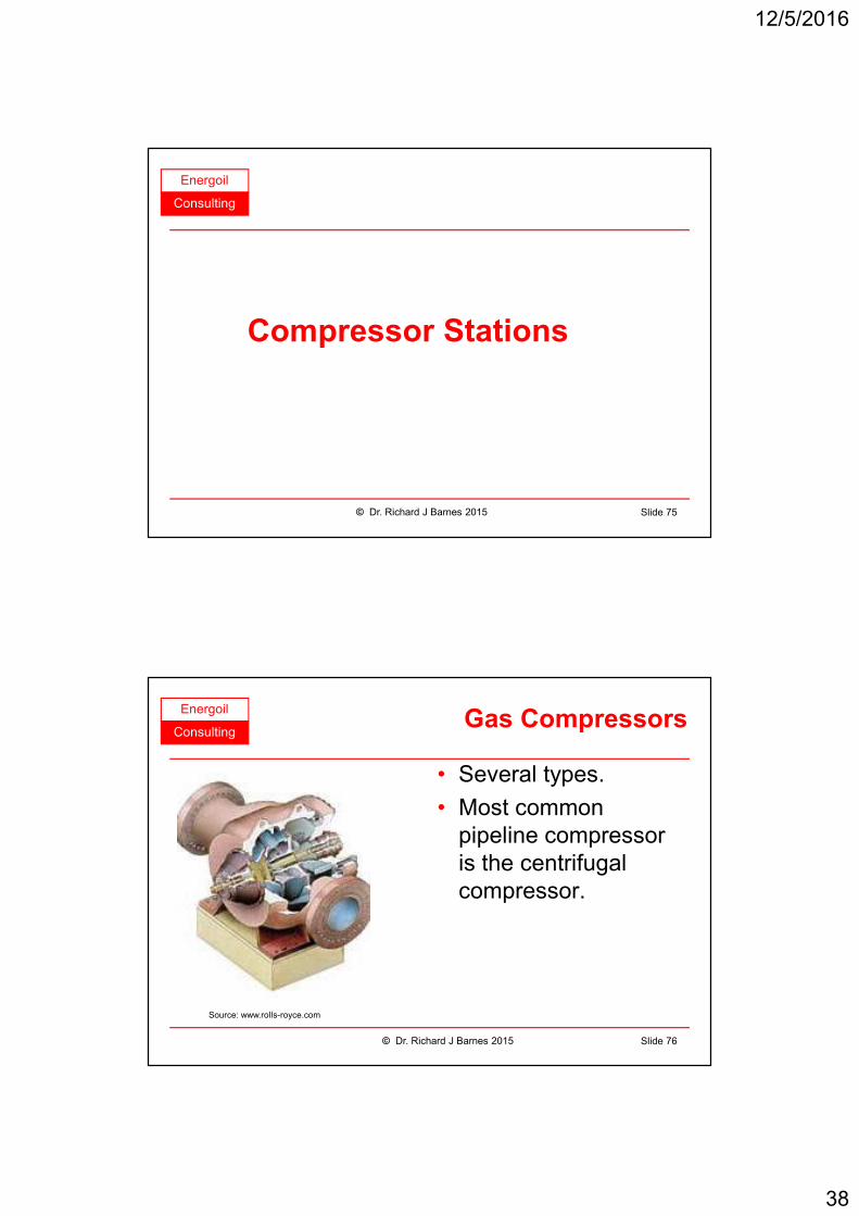
ConsultingGas Compressors
• Several types.
• Most common
pipeline compressor
is the centrifugal
compressor.
Source: www.rolls-royce.com
© Dr. Richard J Barnes 2015 Slide 76

12/5/2016
39
Energoil
ConsultingGas Turbine Drive
• Uses aero-derivative
or industrial gas
turbines.
• Typical power 4 - 52
MW. Source: www.rolls-royce.com
© Dr. Richard J Barnes 2015 Slide 77
Energoil
ConsultingGas Compressor Power
• Four stages in calculation:
– Calculate mass flow rate in kg/hr;
– Calculate head (pressure) developed by
compressor;
– Calculate power required for compression;
– Calculate total power including losses.
© Dr. Richard J Barnes 2015 Slide 78

12/5/2016
40
Energoil
ConsultingMass Flowrate
• Flow often specified in million Sm3/hr
• Conversion to mass flow:
Where:
w = Mass flow, kg/hr Q = Volume flow, Sm3/hr
M = Molecular weight R = Gas constant, 8.314
© Dr. Richard J Barnes 2015 Slide 79
.
QMw
2 842R=
Energoil
ConsultingPressure Head
• Pressure head is given by:
Where:
HIS = Head, N.m/kg Z = Compressibility
R = Gas constant, 8.314 T = Inlet temperature, °K
P1 = Inlet pressure, kPa (abs) P2 = Outlet pressure, kPa (abs)
M = Molecular weight k = Isentropic exponent, Cp/Cv
-
-( - ) /
k 1
k2
IS
1
ZRT PH 1
M k 1 k P
=
© Dr. Richard J Barnes 2015 Slide 80

12/5/2016
41
Energoil
ConsultingGas Power
• Gas power, actual compression power is
given by:
Where:
GP = Gas power, kW w = Mass flow, kg/hr
HIS = Head, N.m/Kg ηIS = Isentropic efficiency
,IS
p
IS
wHG
3 600η=
© Dr. Richard J Barnes 2015 Slide 81
Energoil
ConsultingTotal Power
• Total power includes losses due to seals and
bearings.
• Mechanical losses can be estimated from:
Losses = 0.75 * GP0.4
• To calculate the brake power:
BP = GP + mechanical losses
© Dr. Richard J Barnes 2015 Slide 82
12/5/2016
42
Energoil
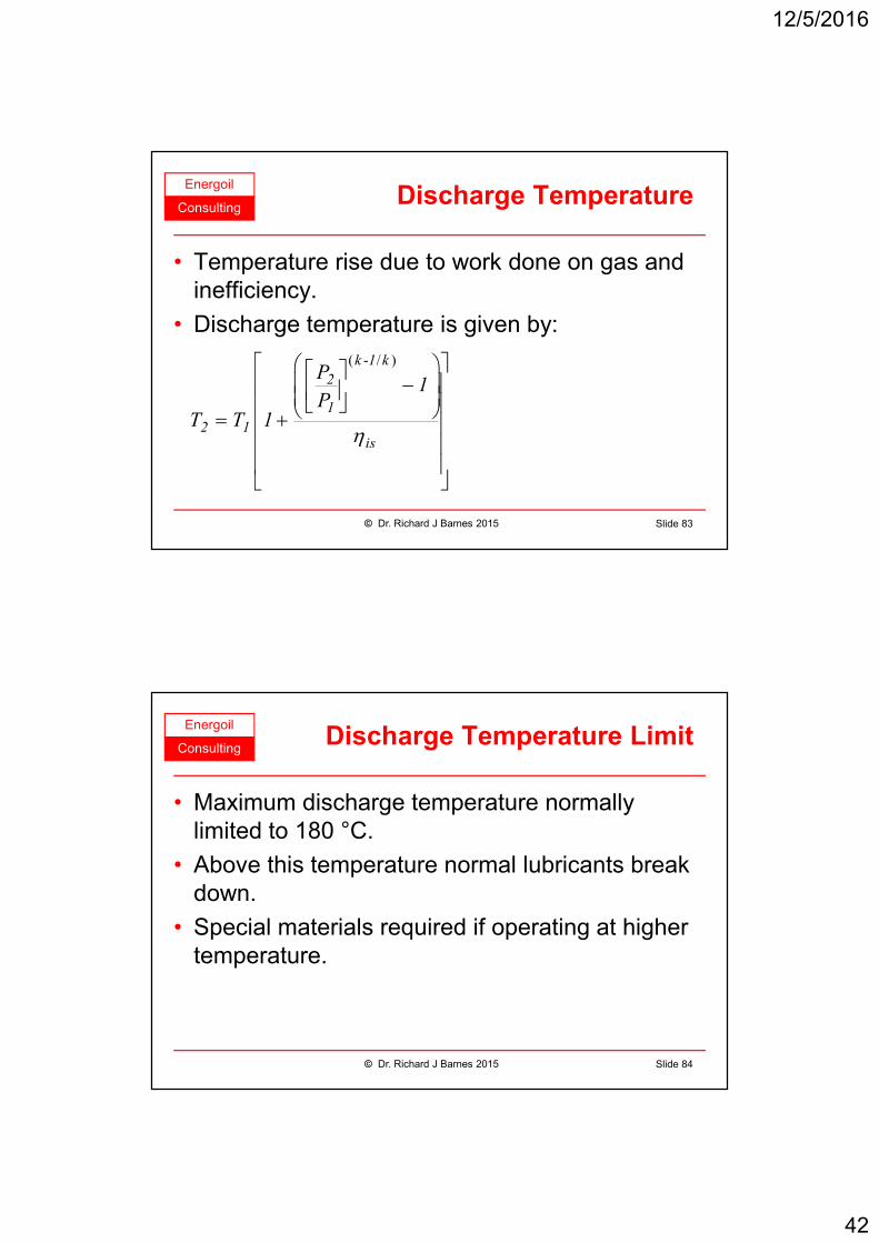
ConsultingDischarge Temperature
• Temperature rise due to work done on gas and
inefficiency.
• Discharge temperature is given by:
( - / )
η
− = +
k 1 k
2
1
2 1is
P1
PT T 1
© Dr. Richard J Barnes 2015 Slide 83
Energoil
ConsultingDischarge Temperature Limit
• Maximum discharge temperature normally
limited to 180 °C.
• Above this temperature normal lubricants break
down.
• Special materials required if operating at higher
temperature.
© Dr. Richard J Barnes 2015 Slide 84

12/5/2016
43
Energoil
ConsultingCompressor Power Example (1)
© Dr. Richard J Barnes 2015 Slide 85
Symbol Parameter Value
Q Volumetric flowrate, Sm3/hr 50,000
M Molecular weight 17.3
P1 Inlet pressure, kPa (g) 500
P2 Outlet pressure, kPa (g) 2,000
T Inlet temperature, °C 35
Z Compressibility 0.87
k Isentropic exponent 1.26
η Isentropic efficiency 0.71
Energoil
ConsultingCompressor Power Example (2)
• Mass flowrate:
w = 36,609 kg/hr
© Dr. Richard J Barnes 2015 Slide 86
.
QMw
2 842R=
, .
. .
×=
×50 000 17 3
w2 842 8 314

12/5/2016
44
Energoil
ConsultingCompressor Power Example (3)
• Pressure head is:-
-( - ) /
=
k 1
k2
IS1
ZRT PH 1
M k 1 k P
© Dr. Richard J Barnes 2015 Slide 87
. -
.. . ( ) , .-
. ( . - ) / . .
× × + + = × +
1 26 1
1 26
IS
0 87 8 314 35 273 2 000 101 325H 1
17 3 1 26 1 1 26 500 101 325
. . /=ISH 183 834 N m kg
Energoil
ConsultingCompressor Power Example (4)
• Gas power is:
,IS
p
IS
wHG
3 600η=
© Dr. Richard J Barnes 2015 Slide 88
, .
. ,
×=
×p
36 608 183 834G
0 71 3 600
,=pG 2 633 kW
12/5/2016
45
Energoil
ConsultingCompressor Power Example (5)
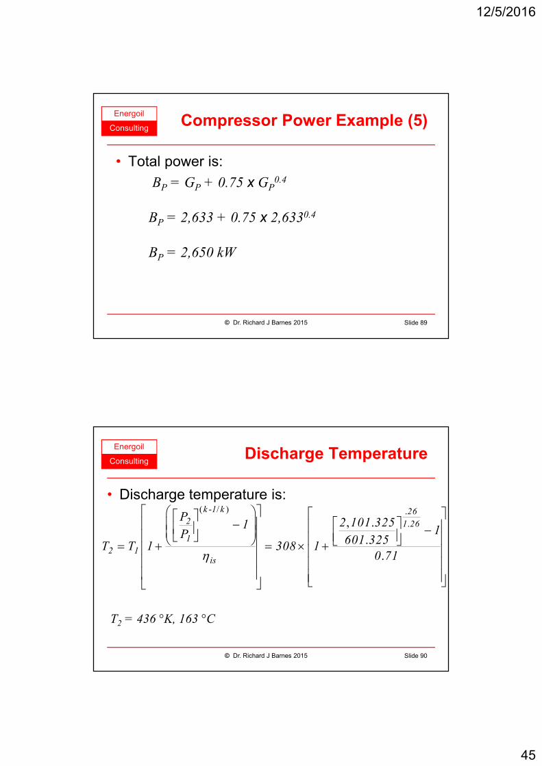
• Total power is:
BP = GP + 0.75 x GP0.4
BP = 2,633 + 0.75 x 2,6330.4
BP = 2,650 kW
© Dr. Richard J Barnes 2015 Slide 89
Energoil
ConsultingDischarge Temperature
• Discharge temperature is:
T2 = 436 °K, 163 °C
( - / ) .
., .
.
.η
− − = + = × +
k 1 k 262 1 26
1
2 1is
P 2 101 3251 1P 601 325T T 1 308 1
0 71
© Dr. Richard J Barnes 2015 Slide 90

12/5/2016
46
Energoil
Consulting
Oil and Gas Storage
© Dr. Richard J Barnes 2015 Slide 91
Energoil
Consulting
Oil Storage
© Dr. Richard J Barnes 2015 Slide 92
12/5/2016
47
Energoil
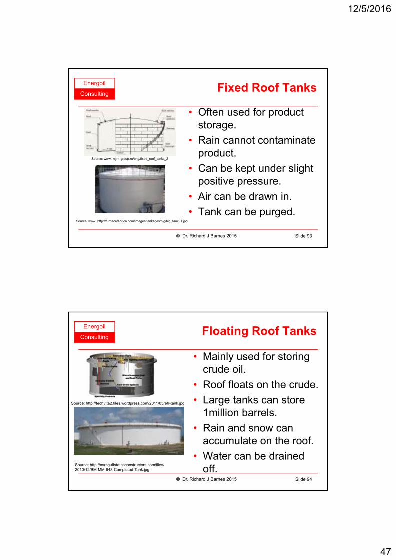
ConsultingFixed Roof Tanks
• Often used for product
storage.
• Rain cannot contaminate
product.
• Can be kept under slight
positive pressure.
• Air can be drawn in.
• Tank can be purged.
Source: www. ngm-group.ru/eng/fixed_roof_tanks_2
© Dr. Richard J Barnes 2015 Slide 93
Source: www. http://furnacefabrica.com/images/tankages/big/big_tank01.jpg
Energoil
ConsultingFloating Roof Tanks
• Mainly used for storing
crude oil.
• Roof floats on the crude.
• Large tanks can store
1million barrels.
• Rain and snow can
accumulate on the roof.
• Water can be drained
off.
Source: http://techvita2.files.wordpress.com/2011/05/efr-tank.jpg
© Dr. Richard J Barnes 2015 Slide 94
Source: http://asrcgulfstatesconstructors.com/files/
2010/12/BM-MM-648-Completed-Tank.jpg
12/5/2016
48
Energoil
Consulting
Gas Storage
© Dr. Richard J Barnes 2015 Slide 95
Energoil
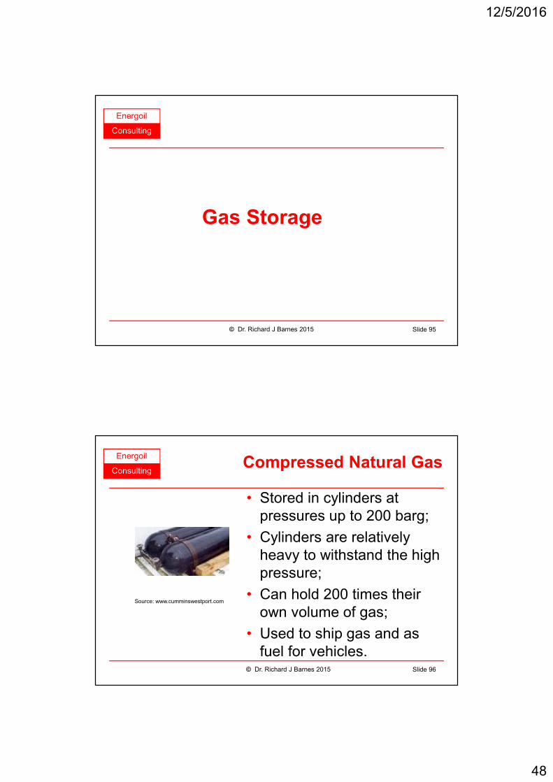
ConsultingCompressed Natural Gas
• Stored in cylinders at
pressures up to 200 barg;
• Cylinders are relatively
heavy to withstand the high
pressure;
• Can hold 200 times their
own volume of gas;
• Used to ship gas and as
fuel for vehicles.
Source: www.cumminswestport.com
© Dr. Richard J Barnes 2015 Slide 96

12/5/2016
49
Energoil
ConsultingUnderground Storage
• Salt domes can be
washed out to form
storage.
• Gas pumped in during
low demand periods.
• Gas produced during
high demand periods.
• Gas may need treating
before distribution.© Dr. Richard J Barnes 2015 Slide 97
Dry gas for
distribution
Dehydrator
Compressor
Feed gas for
storage
Salt deposit
Impervious strata
Salt cavern
leached out
Ground level
Energoil
ConsultingLiquefied Natural Gas
• Stored at atmospheric
pressure and -162 °C;
• Tanks can hold 600
times their own volume;
• Low temperatures
require special insulation
and construction;
• LNG shipped to all over
the world.
Source: www.shell-usgp.com
© Dr. Richard J Barnes 2015 Slide 98
12/5/2016
50
Energoil
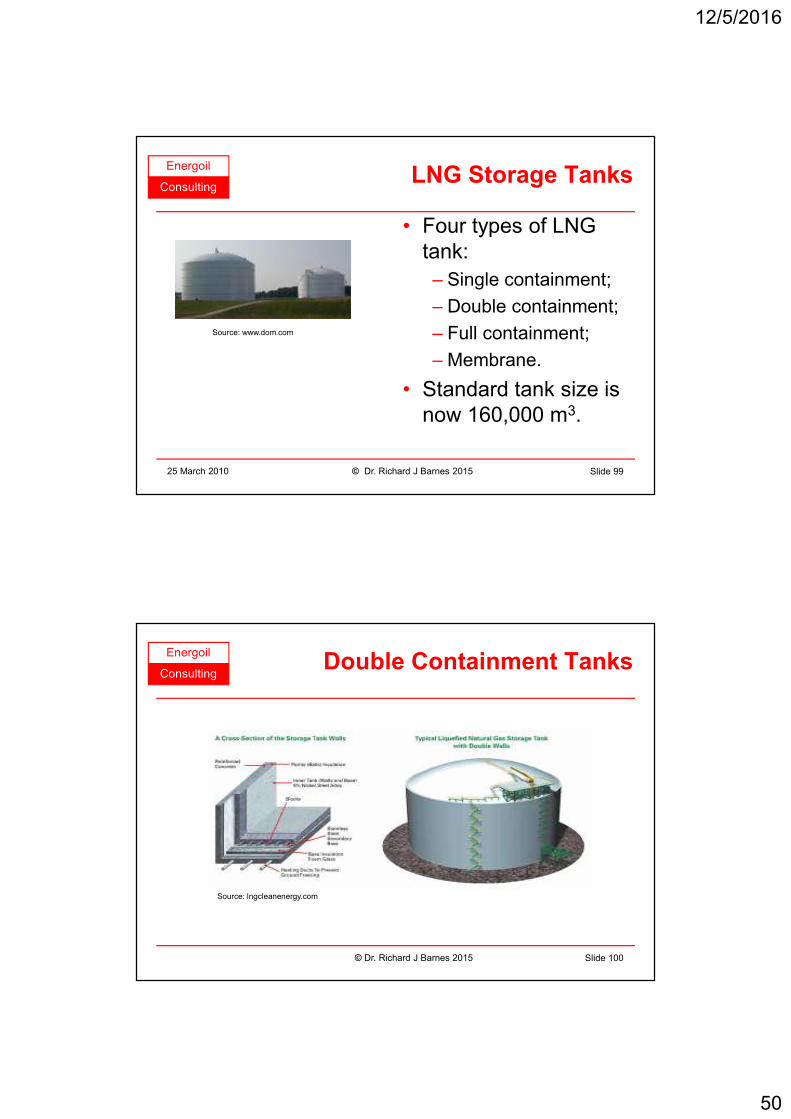
ConsultingLNG Storage Tanks
• Four types of LNG
tank:
– Single containment;
– Double containment;
– Full containment;
– Membrane.
• Standard tank size is
now 160,000 m3.
Source: www.dom.com
25 March 2010 © Dr. Richard J Barnes 2015 Slide 99
Energoil
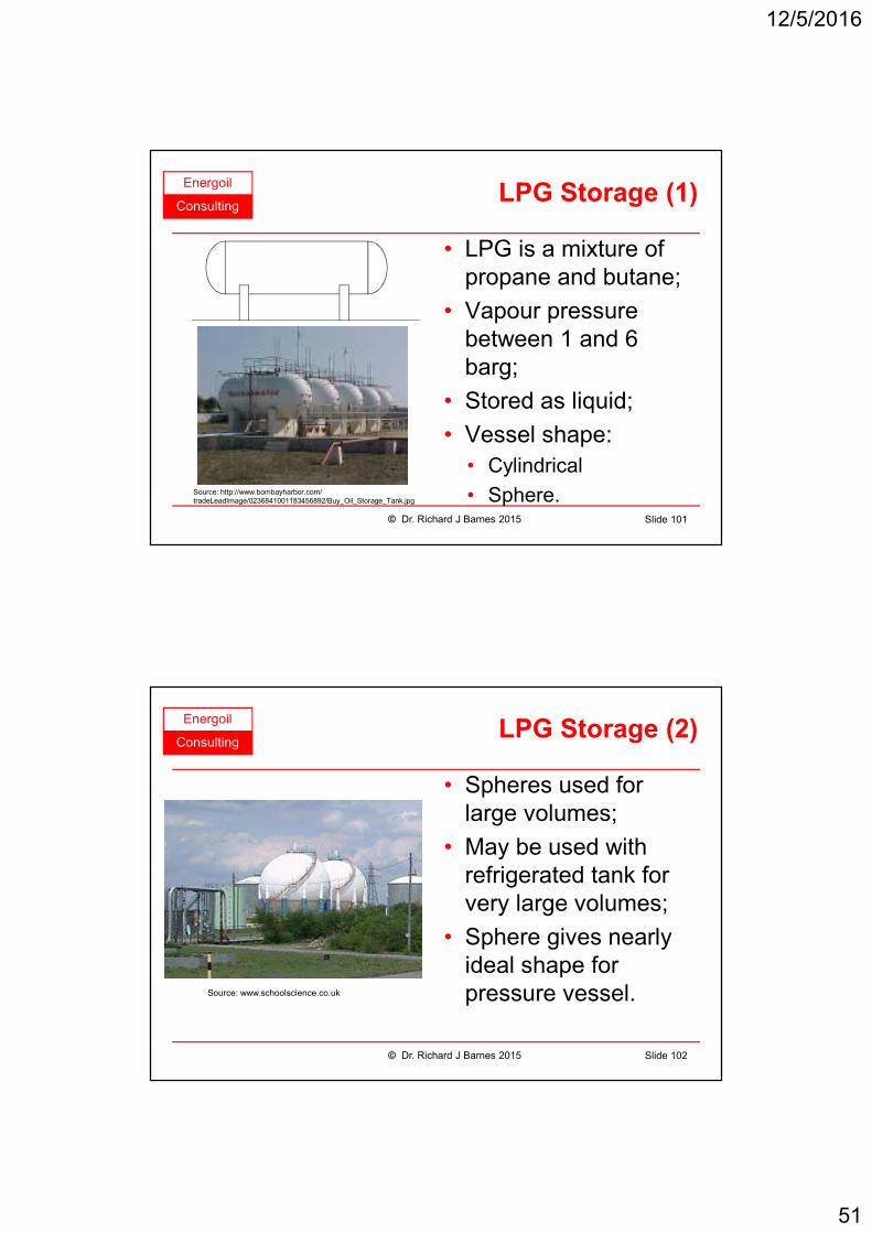
ConsultingDouble Containment Tanks
Source: lngcleanenergy.com
© Dr. Richard J Barnes 2015 Slide 100
12/5/2016
51
Energoil
ConsultingLPG Storage (1)
• LPG is a mixture of
propane and butane;
• Vapour pressure
between 1 and 6
barg;
• Stored as liquid;
• Vessel shape:
• Cylindrical
• Sphere.© Dr. Richard J Barnes 2015 Slide 101
Source: http://www.bombayharbor.com/
tradeLeadImage/0236841001183456892/Buy_Oil_Storage_Tank.jpg
Energoil
ConsultingLPG Storage (2)
• Spheres used for
large volumes;
• May be used with
refrigerated tank for
very large volumes;
• Sphere gives nearly
ideal shape for
pressure vessel.Source: www.schoolscience.co.uk
© Dr. Richard J Barnes 2015 Slide 102
12/5/2016
52
Energoil
Consulting
End of
Presentation
© Dr. Richard J Barnes 2015 Slide 103