lecture 12 cad and parameters - rice university€¦ · · 2015-12-03depend on cad capabilities...
TRANSCRIPT

1 © 2015 ANSYS, Inc. February 27, 2015
16.0 Release
Lecture 12 CAD and Parameters
Introduction to ANSYS Mechanical

2 © 2015 ANSYS, Inc. February 27, 2015
Chapter Overview
In this chapter, interoperability with CAD software as well as parameters will be discussed.
A. CAD Import
B. Defining Parameters in Workbench
C. Using the Parameter Workspace
D. Updating CAD Parameters
E. Workshop 12.1 – Parameter Management
Some CAD functionality are specific to certain CAD software, so these will be designated accordingly.
• Not all CAD software have the same features so there are some differences in CAD-related functionality which is supported in Mechanical.

3 © 2015 ANSYS, Inc. February 27, 2015
A. CAD Import
Numerous Geometry Interfaces are available for commercial CAD systems:
• For the latest information on CAD geometry interfaces and supported platforms see the ANSYS Workbench Mechanical documentation.
Geometry Interface licenses can be run in reader mode for all licenses.
Geometry Interfaces can be run in plug-in mode for the CAD software listed under “Associative”.
DesignModeler is the Workbench geometry application and supports all the functions and capabilities listed for commercial CAD systems.
• Note the SpaceClaim Direct modeler also supports these features.
Please note, not all import capabilities described here are available with all CAD systems. Features depend on CAD capabilities and the support provided through the CAD vendor’s API.

4 © 2015 ANSYS, Inc. February 27, 2015
Workbench geometry properties control the import of numerous CAD items in addition to geometry:
• Parameters, Coordinate Systems, Material properties, etc.
To display geometry import properties:
• RMB > Properties, or
• View > Properties.
Geometry Interface Availability
ACIS (.SAT) ×
AutoCAD ×
Autodesk Inventor ×
Catia V4 ×
Catia V5 ×
Catia V6 ×
Creo Parametric ×
Design Modeler ×
Gambit ×
IGES ×
JT Reader ×
Monte Carlo N-Particle ×
NX ×
Parasolid ×
Solid Edge ×
SolidWorks ×
SpaceClaim ×
STEP ×
… CAD Import

5 © 2015 ANSYS, Inc. February 27, 2015
Import solid, surface, or line bodies:
• Assemblies with mixed solids and surfaces are OK.
• Select desired geometry type to filter import.
• Cannot import a part with mixed solids and surfaces.
Use Associativity:
• Allows updating CAD geometry in Mechanical without redefining material properties, loads, supports, etc..
Smart CAD Update:
• only modified components of a CAD assembly are updated.
… CAD Import

6 © 2015 ANSYS, Inc. February 27, 2015
Local Coordinate systems:
• Allows local CS from CAD models to import with geometry. See current documentation for CAD system support.
… CAD Import

7 © 2015 ANSYS, Inc. February 27, 2015
… CAD Import Parametric CAD dimensions can be imported into Mechanical.
• Check Parameters:
– The “Parameter Key” provides a filter. When used, only parameters whose names contain the key will be imported (default is “DS”).
– Note, multiple filters can be used by separating each with “;” (e.g. NS; AB; VR).
– To import all CAD parameters leave the parameter key field blank.
CAD parameters will appear in the Details view for the part.

8 © 2015 ANSYS, Inc. February 27, 2015
Groups defined in CAD systems can be imported as Named Selections.
Check the “Named Selections” box:
• The Named Selection key provides a filter. When used only groups containing the specified prefix in their name will be imported (default is “NS”).
– Note, multiple filters can be used by separating each with “;” (e.g. NS; AB; VR).
• To import all groups leave the named selection key field blank.
• Imported Named Selections appear in the tree.
… CAD Import

9 © 2015 ANSYS, Inc. February 27, 2015
For most CAD systems Workbench offers an alternate way of working with groups of geometry via the Named Selection Manager in the CAD system.
• Access the NS Manager from the ANSYS menu within the CAD system.
• Once opened the NS Manager allows groups to be created independent of the internal CAD groups. Create, Select, Delete, etc. operations
Sample menu from CAD
… CAD Import

10 © 2015 ANSYS, Inc. February 27, 2015
Material Properties assigned in a CAD system can be imported to Workbench (Engineering Data).
Check “Material Properties”:
• Materials imported from CAD will appear in “Engineering Data”
• Material assignments will match the CAD material assignments.
… CAD Import

11 © 2015 ANSYS, Inc. February 27, 2015
B. Defining Parameters in Workbench Parameters are defined in Mechanical by toggling the parameter flag on/off.
• Click in the square and a blue “P” will appear.
• Material properties are parameterized in the engineering data application.
Example of input parameters
Example of output parameters
CAD parameters must be flagged as well to allow access in Workbench (otherwise they are read only).
12 © 2015 ANSYS, Inc. February 27, 2015
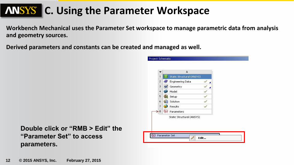
C. Using the Parameter Workspace
Workbench Mechanical uses the Parameter Set workspace to manage parametric data from analysis and geometry sources.
Derived parameters and constants can be created and managed as well.
Double click or “RMB > Edit” the
“Parameter Set” to access
parameters.

13 © 2015 ANSYS, Inc. February 27, 2015
Parameter information is presented in a series of tables:
• Outline: lists all input, output or derived parameters.
• Property: lists information regarding the parameter highlighted in the outline.
Table of Design Points: allows multiple
parameter configurations to be
prepared before solving
Outline
Table of DP
Properties
. . . Using the Parameter Workspace

14 © 2015 ANSYS, Inc. February 27, 2015
. . . Using the Parameter Workspace To modify a parameter value one can enter a new value in the “Value” field in the Outline window then Update/Refresh the project.
Create custom parameters by entering expressions. Expressions can be created using functions or by using already existing parameters.
Where necessary units can be entered using braces
(e.g 1*[mm]).

15 © 2015 ANSYS, Inc. February 27, 2015
Use the Table of Design Points to enter multiple values for input parameters. This allows a number of scenarios to be predefined for study.
Once the DP Table is completed choose “Update All Design Points” to automate solving each scenario. By default each scenario overwrites the previous one keeping only the output parameter values. If you wish to retain complete solutions check the “Exported” box next to any or all rows.
. . . Using the Parameter Workspace

16 © 2015 ANSYS, Inc. February 27, 2015
Example using design points: A CAD dimension has been promoted to a WB input parameter.
• The stress in a particular region of the model is promoted as an output parameter.
• The mass of the geometry has also been promoted to a parametric output.
. . . Using the Parameter Workspace

17 © 2015 ANSYS, Inc. February 27, 2015
Example . . .
Opening the parameter workspace, the parameters can be seen in the outline.
In the table of design points 3 new
values are added to the current CAD
parameter value.
From the top menu “Update All Design
Points” is selected.
. . . Using the Parameter Workspace

18 © 2015 ANSYS, Inc. February 27, 2015
Example . . .
The progress of the updates is reflected in the table.
With updates complete various charts can be created to investigate the data.
Stress vs Fillet
Radius
. . . Using the Parameter Workspace
19 © 2015 ANSYS, Inc. February 27, 2015
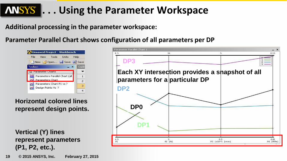
Additional processing in the parameter workspace:
Parameter Parallel Chart shows configuration of all parameters per DP
Vertical (Y) lines
represent parameters
(P1, P2, etc.).
Horizontal colored lines
represent design points.
DP3
DP0
DP2
DP1
Each XY intersection provides a snapshot of all
parameters for a particular DP
. . . Using the Parameter Workspace

20 © 2015 ANSYS, Inc. February 27, 2015
By highlighting parameters, different chart configurations can be selected.
With P1 highlighted notice the chart options are with respect to this parameter.
After selecting (double click) the desired chart to configure the display.
. . . Using the Parameter Workspace

21 © 2015 ANSYS, Inc. February 27, 2015
. . . Using the Parameter Workspace
As charts are created they are stored in the outline window and can be retrieved by highlighting them.
• Using a RMB in various areas of the chart users can “Edit Properties . . .” to control colors, styles, symbols, interpolation type, etc.
• Legend, line display, background, etc..

22 © 2015 ANSYS, Inc. February 27, 2015
D. Updating CAD Parameters (From CAD)
Update From CAD (Project Schematic):
• After modifying the geometry in the CAD system, RMB the “Geometry” cell and “Update From CAD”. This will update the Mechanical geometry to match the CAD system.

23 © 2015 ANSYS, Inc. February 27, 2015
. . . Updating CAD Parameters (From WB)
• Update from Workbench:
• Make sure CAD parameter is promoted in Mechanical.
• Modify parameter value in WB Parameter Set.
• Refresh: causes CAD and Mechanical geometry to match new parameter values.
• Update: causes CAD and Mechanical geometry to update and remesh.

24 © 2015 ANSYS, Inc. February 27, 2015
• Workshop 12.1 – Parameter Management
• Goal: Use the Workbench Parameter Workspace to setup multiple scenarios to explore
structural responses in the bracket shown. Material thickness will be varied in the gusset with the bracket thickness held constant then the process will be reversed.
E. Workshop 12.1