leak test procedure - woods powr-grip · tst-016 – rev. 2014-086 page 1 of 17 leak test procedure...
TRANSCRIPT

TST-016 – Rev. 2014-086 Page 1 of 17
LEAK TEST PROCEDURE
GENERIC GUIDE TO LEAK DETECTION FOR VACUUM LIFTERS
TESTING AND MAINTENANCE MUST BE
DONE BY A QUALIFIED PERSON
KEEP FOR FUTURE REFERENCE

TST-016 – Rev. 2014-086 Page 2 of 17
THIS PAGE INTENTIONALLY LEFT BLANK

TST-016 – Rev. 2014-086 Page 3 of 17
UNDERSTANDING YOUR SYSTEM
If the vacuum system of your lifter has developed a leak, it is necessary to determine the cause
and location of the leak in order to effect repairs. This general guide applies to most types of
Wood’s Powr-Grip powered vacuum lifters. If a specific guide exists for your specific model of
lifter, please refer to it also, since it will provide more detail regarding specific components and
their locations.
Basic Vacuum System Layout
This diagram represents the basic structure of vacuum generating systems found on nearly all of
Wood’s Powr-Grip’s vacuum equipment products.
When the equipment is in “apply” mode, a vacuum pump (or venturi on air powered lifters) draws
air through a control valve assembly evacuating the vacuum pad(s).
In “release” mode, the control valve allows air to re-enter the system causing the vacuum pads to
release. This is accomplished either by opening a valve port to atmosphere or by pumping air
directly into this port from the vacuum pump. The latter function, referred to as “blow-off” is found
on equipment that requires faster release times.
In addition, an air filter with adjoining vacuum gauge is located in the vacuum line between the
control valve and the vacuum pad(s). The vacuum gauge may be mounted directly to the filter or
connect to the vacuum pad side of the filter via hose.
The primary system seal on the majority of our vacuum lifters is a check valve located in the
vacuum line between the control valve assembly and the vacuum pump. The check valve
prevents air from flowing back through the vacuum pump to the vacuum system. On some lifters,
the primary seal is a solenoid valve which, when power is shut off to the vacuum pump (either
manually or by way of vacuum switch settings), closes the port to the vacuum pad system, isolating
it from the vacuum pump port.
If you have determined that your vacuum lifter has a leak and are unsure of what the primary seal
is please contact Wood’s Powr-Grip Co. with your model and serial number. With this information,
additional details can be provided in respect to your specific lifter model.
Note: The information provided in this document is based on the basic vacuum system described
above. If a leak is detected, and particularly if it is determined to be in the vacuum generating
system, having information specific to your particular model may improve your ability to apply the
test information to follow.
TST-016 – Rev. 2014-086 Page 4 of 17
SYMPTOMS OF VACUUM LEAK
DC (battery powered) lifters:
Severe leakage is evidenced by a lifter’s inability to draw full vacuum while attached to clean,
smooth, nonporous surface. In such cases, the vacuum pump runs continuously and the vacuum
level shown on the vacuum gauge will be less than 16" hg [-54 kPa], the red zone of the vacuum
gauge.
Moderate leakage is indicated by intermittent cycling of the vacuum pump and vacuum indicator
light during a lift. If the vacuum generating system turns on more than once every 10 minutes,
leakage is serious enough to warrant repairing the lifter’s vacuum system.
AC or Air powered lifters:
Severe leakage is evidenced by a lifter’s inability to draw full vacuum while attached to clean,
smooth, nonporous surface. In such cases, the vacuum level shown on the vacuum gauge may be
less than 16" hg [-54 kPa], the red zone of the vacuum gauge, or noticeably lower than what the
vacuum system was able to achieve in the past.
Since the vacuum source of this type of lifter runs constantly while in use, moderate leakage may
only be noticed when performing a vacuum test as described in the Maintenance section of the
instruction manual for your lifter.
All vacuum lifters:
To determine if your lifter has a vacuum leak perform the Vacuum Test as described in the
Maintenance section of your instruction manual. Note, if your lifter has quick connects used to
reduce the number of vacuum pads, it should be tested with both the quick connects connected
and disconnected to verify system integrity under all possible conditions.
When performing the vacuum test, if the lifter tests positive for a leak, we recommend that you note
the time and leakage rate such as “lost 5" [-17 kPa] in 10 minutes”. This information can assist in
diagnosing the location of the leak because there may be more than one component leaking
vacuum. For example, when you are performing maintenance, if an isolated section tests positive
for a leak but the leakage rate is less than that of the whole lifter, the indication is that there is still
one or more vacuum leak elsewhere in the system.
If the rate of leakage is sufficient to warrant repair proceed as follows:
To locate the cause of leakage, begin by inspecting the vacuum pads, fittings and hoses of the
entire vacuum system. Look for contamination, cuts or abrasions on pad faces, cracks in suction
stems on the back of pads, cracks, abrasions or cuts in hoses, damaged fittings and loose or
damaged hoses at connection points. If leakage is severe, the cause is often a visibly damaged
part.
Do not apply soapy water to fittings or vacuum hoses in an attempt to find leaks, since it will only
be drawn inside the vacuum system.
If the source of leakage is not immediately evident, the various sections of the entire vacuum
system must be systematically isolated to determine the leakage point. The process to accomplish
this will be described in the tests to follow.

TST-016 – Rev. 2014-086 Page 5 of 17
RECOMMENDED TOOLS
Please note, the information that is gathered when performing a vacuum test is only valid if the
tools used to perform the test are accurate. Be sure that the tools you use are capable of
completely sealing the isolated parts of your system when tested.
Recommended tools, in addition to an appropriate test surface, are plugs for hoses and fittings, a
ball valve with vacuum gauge attached and extra vacuum hose. Hoses should be sized with the
appropriate inside diameter for barbed fittings and outside diameter and hardness for push-in
fittings. The size and type hose will vary based on the model and age of your lifter.
This procedure is written with the assumption that you have access to the appropriate tools. If
needed test equipment is available from Wood’s Powr-Grip Co. and are shown at the end of this
section.
A set of screwdrivers may also be needed if enclosures need to be opened. Note, always proceed
with caution when opening enclosures containing electrical wiring. Wiring is often connected to
components in the cover, as well as the enclosure itself, and hinged covers open only one way, so
open them gently so as not to damage the enclosure or attached wiring.
Note, when removing hoses from barbed fittings take care to avoid damaging the barbs of the
fitting the hose is attached to. Cuts or nicks in fitting barbs can create a leak that did not previously
exist. Additionally, if a hose is removed from a barbed fitting cut approximately ¼” [6mm] off the
end of the hose before reinstalling it on the fitting to remove damaged hose ends.
Cutting a small amount (1/8" [3mm] to 1/4" [6mm]) from the end of a hose used on a push-in style
fitting is also recommended. These are compression style fittings and will typically leave a small
depression in the hose at the point where they compress. Cutting a small portion off relocates this
depression, allowing the fitting to make a good seal in a new location. Additionally, push-in fittings
require that the hose be cut straight and square to seal properly.
For information
concerning test kits
and individual parts,
please contact the
sales staff at
Wood’s Powr-Grip
Co., Inc.
STANDARD PARTS PROVIDED IN BASIC LEAK TEST KIT # 66102
HOSE AND FITTING ADAPTERS PROVIDED IN ACCESSORY KIT #
66102AM

TST-016 – Rev. 2014-086 Page 6 of 17
HOW THE VARIOUS TOOLS ARE USED
The ball valve / gauge assembly:
The primary tool is the ball valve with the vacuum gauge.
This can be used to plug off sections between the lifter’s
vacuum gauge and control valve or vacuum pump
providing a gauge reading when the lifter’s gauge is not
part of the section being tested. An example of this is
shown in FIGURE 1, where the ball valve has been installed
in the line between the vacuum filter and the control valves.
In this instance, the filter is capped off and the ball valve
with gauge installed with the ball valve’s vacuum gauge
towards the control valve. Vacuum was applied and the
ball valve closed. Now the vacuum filter and control valve
are separated into two sections by the (closed) ball valve.
If a leak were noted on the ball valve’s vacuum gauge, it
would indicate that the leak is between the ball valve and
vacuum pump, not the vacuum filter. If a leak were noted on the vacuum filter’s vacuum gauge,
the indication is that the filter assembly is the cause of the leak.
If you did not have the ball valve assembly and a leak was noted when just the filter was plugged
you would not be able to determine which part, from the vacuum filter to the pump, was the cause
of the leak since the gauge is not accessible down line of the filter.
The ball valve provides an additional vacuum gauge that can be located in any section requiring
testing.
The other use of the ball valve is to use it to test individual
components. In FIGURE 2 the hose was removed from a
pad fitting and the valve end of the ball valve was attached
to the hose. An additional piece of hose was attached to
the gauge end of the ball valve and pad fitting installed in
the hose and then capped off with a plug. Vacuum was
applied and then the ball valve was closed. In this instance
if the pad fitting leaked it would be indicated on the ball
valve’s vacuum gauge.
To use the ball valve on vacuum lines larger or smaller than the standard 1/4" i.d. line an adapter
fitting is required. Depending on your model lifter, vacuum lines used on barbed fittings may be
1/8" i.d., 1/4" i.d., 3/8" i.d. or 1/2" i.d. Vacuum lines used with push-in fittings may be 3/8" o.d., 1/4"
o.d. or 5/32" o.d.
FIGURE 1
FIGURE 2
TST-016 – Rev. 2014-086 Page 7 of 17
Plugs and caps:
The plugs and caps are used to cap off fittings in order to isolate individual components or sections
to be tested. This allows you to tell what sections or parts leak vs. those that do not.
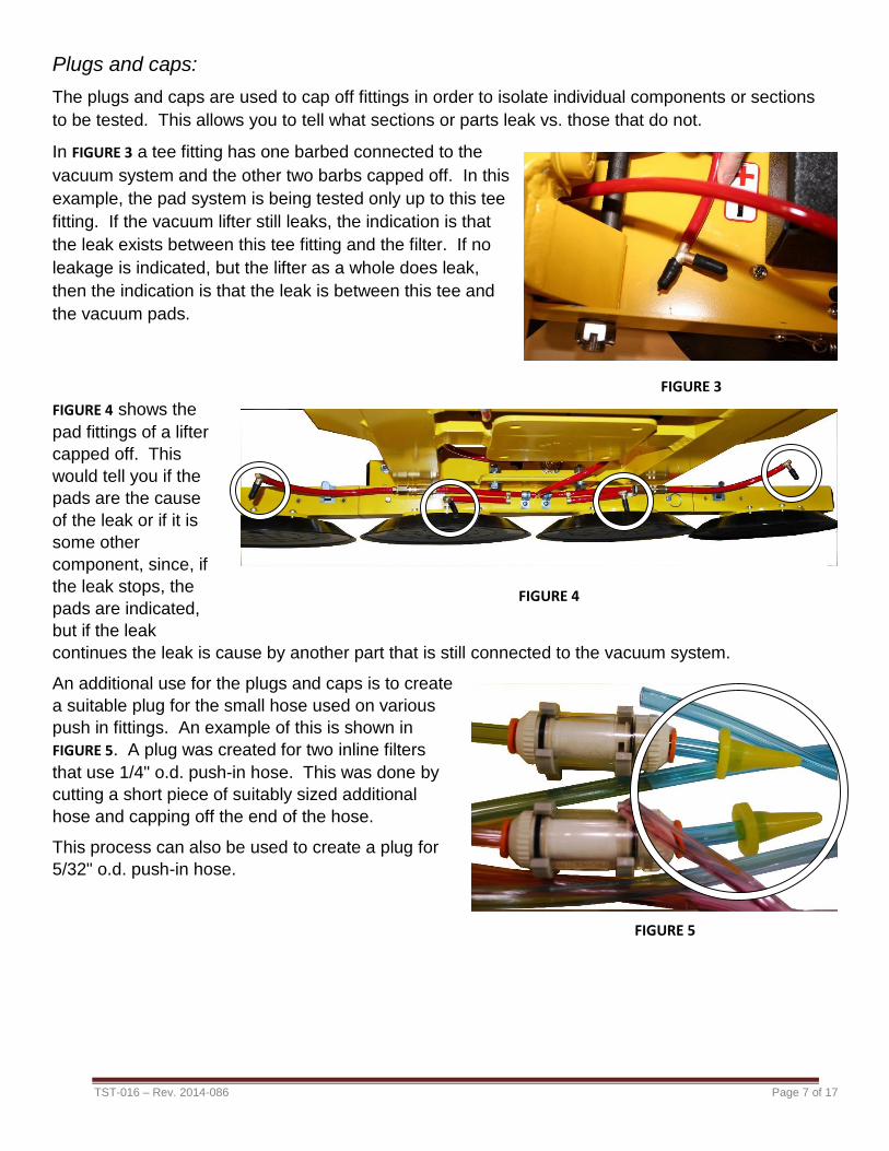
In FIGURE 3 a tee fitting has one barbed connected to the
vacuum system and the other two barbs capped off. In this
example, the pad system is being tested only up to this tee
fitting. If the vacuum lifter still leaks, the indication is that
the leak exists between this tee fitting and the filter. If no
leakage is indicated, but the lifter as a whole does leak,
then the indication is that the leak is between this tee and
the vacuum pads.
FIGURE 4 shows the
pad fittings of a lifter
capped off. This
would tell you if the
pads are the cause
of the leak or if it is
some other
component, since, if
the leak stops, the
pads are indicated,
but if the leak
continues the leak is cause by another part that is still connected to the vacuum system.
An additional use for the plugs and caps is to create
a suitable plug for the small hose used on various
push in fittings. An example of this is shown in
FIGURE 5. A plug was created for two inline filters
that use 1/4" o.d. push-in hose. This was done by
cutting a short piece of suitably sized additional
hose and capping off the end of the hose.
This process can also be used to create a plug for
5/32" o.d. push-in hose.
FIGURE 3
FIGURE 4
FIGURE 5

TST-016 – Rev. 2014-086 Page 8 of 17
LEAK DETECTION PROCESS
The most common problem encountered when dealing with vacuum equipment is leakage.
Essentially any component of a vacuum system may leak, allowing air to enter the system. This
compromises the lifter’s overall efficiency, capacity, and ultimately the ability to operate safely.
Leakage is determined by performing a standard vacuum test as described in the instruction
manual provided with every lifter. If during this test a loss in vacuum is noted, it indicates that a
leak is present somewhere within the system. If the leak is significant, it should be located and
repaired prior to using the lifter. For lifters used on smooth, non-porous materials, significant
leakage is typically considered to be more than 4" Hg. [-14 kPa] in 10 minutes or less, as shown on
the vacuum gauge, when testing on this type surface (as recommended by the leak test).
The vacuum system of vacuum lifters is comprised of two major sections: the “vacuum generating
system” and the “vacuum pad system”. The dividing point for these sections is typically considered
to be the vacuum filter assembly.
Leaks are located by isolating the sections of the vacuum system and performing vacuum tests
that ultimately will identify the component(s) causing the leak. This is a trial and error process
where you can accurately determine which parts are leaking by first identifying which parts do not
leak.
To begin this process, first perform a standard vacuum test with all components attached to know
the total rate of the leak. This will help determine if there is more than one component involved,
by comparing this rate to the rate of leakage found as sections are disconnected from the system
e.g., if the rate of leakage when testing the vacuum generating system is only half the rate noted
as when the entire system was tested, you can determine that there is more than one component
involved and that at least one leak exists in both the vacuum generating system and the vacuum
pad system.
To perform the vacuum test, clean the vacuum pads and attach the lifter to a clean, non-porous
surface. Turn on the lifter and switch the lifter to the apply position. Allow the system to reach a
suitable vacuum level, then, with the lifter still in apply, turn off or disconnect the power. Note, DC
lifters may shut off automatically but the power will still need to be disconnected for the test.
Once the system as a whole is tested, the lifter should be divided into sections (typically at the filter
assembly) and testing continued, working either forward or back through the system until the leak
is no longer present. This is described in the Preliminary Test to follow.
TST-016 – Rev. 2014-086 Page 9 of 17
PRELIMINARY TEST
This test determines whether leakage is located in the vacuum generating system or the pad
system.
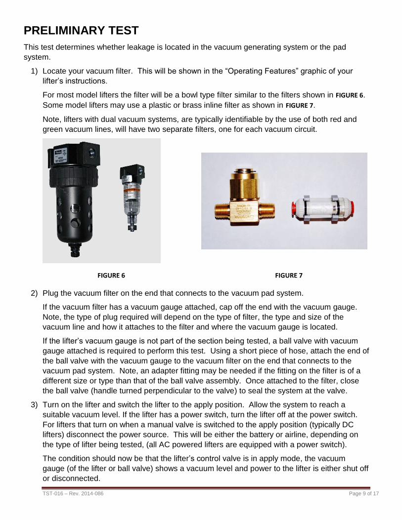
1) Locate your vacuum filter. This will be shown in the “Operating Features” graphic of your
lifter’s instructions.
For most model lifters the filter will be a bowl type filter similar to the filters shown in FIGURE 6.
Some model lifters may use a plastic or brass inline filter as shown in FIGURE 7.
Note, lifters with dual vacuum systems, are typically identifiable by the use of both red and
green vacuum lines, will have two separate filters, one for each vacuum circuit.
2) Plug the vacuum filter on the end that connects to the vacuum pad system.
If the vacuum filter has a vacuum gauge attached, cap off the end with the vacuum gauge.
Note, the type of plug required will depend on the type of filter, the type and size of the
vacuum line and how it attaches to the filter and where the vacuum gauge is located.
If the lifter’s vacuum gauge is not part of the section being tested, a ball valve with vacuum
gauge attached is required to perform this test. Using a short piece of hose, attach the end of
the ball valve with the vacuum gauge to the vacuum filter on the end that connects to the
vacuum pad system. Note, an adapter fitting may be needed if the fitting on the filter is of a
different size or type than that of the ball valve assembly. Once attached to the filter, close
the ball valve (handle turned perpendicular to the valve) to seal the system at the valve.
3) Turn on the lifter and switch the lifter to the apply position. Allow the system to reach a
suitable vacuum level. If the lifter has a power switch, turn the lifter off at the power switch.
For lifters that turn on when a manual valve is switched to the apply position (typically DC
lifters) disconnect the power source. This will be either the battery or airline, depending on
the type of lifter being tested, (all AC powered lifters are equipped with a power switch).
The condition should now be that the lifter’s control valve is in apply mode, the vacuum
gauge (of the lifter or ball valve) shows a vacuum level and power to the lifter is either shut off
or disconnected.
FIGURE 6 FIGURE 7

TST-016 – Rev. 2014-086 Page 10 of 17
4) Observe the vacuum gauge to locate the general area of leakage.
If the vacuum level on the vacuum gauge holds steady and does not drop, the indication
is that the vacuum generating system does not leak, indicating that the leak is located in
the pad system. Proceed to the Pad System Test.
If the vacuum level on the vacuum gauge starts and continues to drop, this indicates the
vacuum generating system does leak. Proceed to the Vacuum Generating System Test.
Note, if the leakage rate observed during this test is noticeably less than the rate
observed when the lifter as a whole was tested, this indicates that a leak may be present
in both the vacuum generating system and the pad system. When this is the case, the
leak in the vacuum generating system should be repaired before proceeding to the pad
system.
However, if the leakage rate is not significant at this point you may proceed with repairs to
the pad system with the knowledge that once the leakage rate drops to the rate noted in
this test, any leaks in the pad system have likely been found and repaired.
VACUUM GENERATING SYSTEM TEST:
At this point, the specific type of lifter will determine what components can actually be tested and
what conclusions can be derived from those tests. The standard combinations are as follows:
Type A: Manual control valve assembly connected to vacuum filter assembly via hose connection.
Type B: Electric (solenoid) control valve assembly connected to vacuum filter assembly via hose
connection.
Type C: Manual control valve assembly connected directly to vacuum filter assembly via fittings
(hard connection).
On most lifters the vacuum gauge is mounted either directly to the pad side of the vacuum filter
or connected to the pad system itself via hose. Since the vacuum gauge is located on the pad side
of the filter, you will lose access to the lifter’s vacuum gauge once you move beyond the vacuum
filter towards the pump. In this scenario, a ball valve with vacuum gauge is required for the
following tests.
The following assumes you have access to suitable plugs, a ball valve with vacuum gauge, and
additional hose for connecting the ball valve to the lifter’s vacuum lines and fittings.
Lifters with manual or electric control valve assembly connected to vacuum filter
assembly via hose connection (types A and B above):
Note: For type C above, manual control valve assembly connected directly to vacuum filter
assembly via fittings, proceed to step 11.
1) Identify the hose that connects the vacuum filter assembly with the control valve assembly.
Remove this hose from the vacuum filter.
2) Install the end of the ball valve assembly with the vacuum gauge into this hose. Note, this
may require the use of a hose adapter if the hose is a size other than 1/4" i.d.

TST-016 – Rev. 2014-086 Page 11 of 17
Close the ball valve (handle turned perpendicular to the valve) to seal the system at the
valve.
3) Turn on the lifter and switch the lifter to the apply position. Allow the system to reach a
suitable vacuum level, then either turn off or disconnect power to the lifter while leaving it in
apply mode.
4) Observe the vacuum gauge on the ball valve to locate the area of leakage.
If the vacuum level on the ball valve’s vacuum gauge holds steady and does not drop this
indicates the leak is located in the filter assembly. Closely inspect the filter assembly.
This is best accomplished by referring to the filter maintenance section of your instruction
manual for any warnings in respect to the type filter used on your lifter.
Check that bowls or caps are tight. That, if a plastic style bowl or filter, that there are no
visible signs of cracks or damage. If a filter assembly with fittings and/or vacuum gauge
attached, that there are no damaged or cracked fittings and the gauge appears to be in
good shape. If it is a filter with push-in style fittings, check that the ends of the hoses are
cut square, that the hoses are pushed in securely, and that there is not excessive pull or
side pressure on the hose.
Additionally, if the filter has been recently serviced, check that it was done thoroughly and
correctly. Consult servicing instructions or contact Wood’s Powr-Grip for information on
servicing your filter.
Repair or replace parts as needed, noting that sometimes it is easier to replace the
assembly than to guess at which individual part may be the cause of the leak.
If the vacuum level on the ball valve’s vacuum gauge starts and continues to drop, this
indicates the leak is located between the ball valve and the vacuum pump.
This includes the hose from the filter to the control valve, the control valve itself and, on
lifters where a check valve is used between the pump and control valve, the check valve.
5) Remove the ball valve from the hose that was connected to the filter. Disconnect the hose
from the control valve. Attach a piece of (new) hose to the end of the ball valve with the
vacuum gauge and attach the other end of this hose to the control valve. Close the ball valve
and repeat the vacuum test above with the new hose attached.
If the vacuum level on the ball valve’s vacuum gauge holds steady and does not drop this
indicates the leak is located in the hose from the control valve to the filter. Replace the
hose.
If the vacuum level on the ball valve’s vacuum gauge starts and continues to drop, this
indicates the leak is located between the ball valve and the vacuum pump.
6) What additional tests can be performed will depend on 1) does your model lifter use a check
valve between the vacuum pump and the control valve and 2) that, if a check valve is used,
where is it located.
If you need assistance in determining if your lifter has a check valve and where it is located
please note the model and serial number of your lifter and contact Wood’s Powr-Grip Co.,
Inc. for information regarding your particular lifter.

TST-016 – Rev. 2014-086 Page 12 of 17
If it was determined that your model lifter does not use a check valve or if a check valve is
used, and is attach to the vacuum pump assembly and then connected to the control valve
via a hose connection proceed to step 7.
If the lifter has a check valve and it is connected directly to the control valve via fittings
proceed to step 9.
7) Remove the ball valve from the control valve and cap the port of the control valve that the
hose was connected to. Remove the hose from the control valve that connects it to the
vacuum pump. Using the ball valve with a hose attached to the end with the vacuum gauge,
attach the hose to the control valve and connect the hose that runs to the vacuum pump to
the other end of the ball valve. With the ball valve in the open position (handle in line with the
valve), turn on the lifter and switch the lifter to the apply position. Allow the system to reach a
suitable vacuum level, then close the ball valve (handle turned perpendicular to the valve)
and either turn off or disconnect power to the lifter while leaving it in apply mode.
8) Observe the vacuum gauge on the ball valve to locate the area of leakage.
If the vacuum level on the ball valve’s vacuum gauge holds steady and does not drop this
indicates the leak is not located in the control valve and that, since the leak was still
evident in step 5, there is likely a check valve located in the system and that it is the
cause of the leak. Locate and replace the check valve.
If the vacuum level on the ball valve’s vacuum gauge starts and continues to drop, this
indicates the leak is located in the control valve assembly.
Note the model and serial number of your lifter and contact Wood’s Powr-Grip Co., Inc. for
additional assistance and information.
9) If the check valve is connected to the control valve via fittings (hard connection), an additional
ball valve is needed to continue testing.
In this instance, the ball valve with test gauge attached will still be attached to the control
valve assembly as it was described in step 5 (ball valve closed, vacuum gauge towards the
control valve). An additional ball valve needs to be installed between the control valve and
the vacuum pump, vacuum gauge end toward the control valve.
With the ball valve between the vacuum pump and control valve in the open position, turn on
the lifter and switch the lifter to the apply position. Allow the system to reach a suitable
vacuum level, then close the ball valve and either turn off or disconnect power to the lifter
while leaving it in apply mode.
10) Observe the vacuum gauge on the ball valve located on the filter side of the control valve to
locate the area of leakage.
If the vacuum level on the ball valve’s vacuum gauge holds steady and does not drop this
indicates the leak is located in the check valve. Locate and replace the check valve.
If the vacuum level on the ball valve’s vacuum gauge starts and continues to drop, this
indicates the leak is located in the control valve assembly.
If the vacuum level on both vacuum gauges starts and continues to drop, this indicates
that both the control valve and the check valve are leaking.

TST-016 – Rev. 2014-086 Page 13 of 17
If it is determined that the leak is in the control valve (regardless of whether or not the
check valve is involved) note the model and serial number of your lifter and contact
Wood’s Powr-Grip Co., Inc. for additional assistance and information.
Lifters with manual control valve assembly connected directly to vacuum filter
assembly via fittings (type C above):
11) If the filter is connected via fittings (hard connection) to the control valve, there is no sure
way to determine the faulty component. Options are as follows:
If the check valve is connected to the vacuum pump and then connected to control valve via
a hose connection proceed to step 12.
If the check valve is connected directly to the control valve via fittings (hard connection),
proceed to step 16.
12) If the check valve is connected to the vacuum pump and then connected to control valve via
a hose connection an additional test can be performed to determine if the check valve is the
cause of the leak and not the control valve/filter assembly.
13) Using a plug, cap off the filter where it connects to the vacuum pad system. Using an
additional piece of hose, connect the end of the ball valve with the vacuum gauge to the
fitting of the control valve that connects to the vacuum (intake) port of the vacuum pump and
connect the other end of the ball valve to the hose running to the pump / check valve
assembly.
14) With the ball valve in the open position (handle in line with the valve), turn on the lifter and
switch the lifter to the apply position. Allow the system to reach a suitable vacuum level, then
close the ball valve (handle turned perpendicular to the valve) and either turn off or
disconnect power to the lifter while leaving it in apply mode.
15) Observe the vacuum gauge on the ball valve to locate the area of leakage.
If the vacuum level on the ball valve’s vacuum gauge holds steady and does not drop this
indicates that the leak is located in the check valve. Locate and replace the check valve.
If the vacuum level on ball valve’s vacuum gauge starts and continues to drop, this
indicates the leak is located in the control valve/filter assembly.
16) If the check valve is connected directly to the control valve/filter assembly via fittings or if it
was determined in step 15 that the control valve/filter assembly is the cause of the leak the
only remaining option is to check the assembly.
17) Examine the filter and control valve for indications of cracked or damaged fittings. Check
that bowls or caps are tight and that there are no cracks or visible damage to the filter or
attached fittings. If the filter has been recently serviced, check that it was done thoroughly
and correctly. Consult servicing instructions or contact Wood’s Powr-Grip for information on
servicing your filter.
Repeat the last test performed. If the leak continues contact Wood’s Powr-Grip Co., Inc. for
additional assistance and information.

TST-016 – Rev. 2014-086 Page 14 of 17
PAD SYSTEM TEST:
Isolate the vacuum pads, fittings and vacuum line sections until the leak point can be located, as
follows:
1) Remove the cap or ball valve from the filter’s barbed fitting and reconnect the vacuum line to
the pad system.
2) Remove and cap each pad fitting as
shown in FIGURE 8, disconnecting all the
pads from the vacuum system.
3) Turn on the lifter and switch the lifter to
the apply position. Allow the system to
reach a suitable vacuum level, then
either turn off or disconnect power to
the lifter while leaving it in apply mode.
4) Observe the vacuum gauge on the ball
valve to locate the area of leakage.
If the vacuum level on the vacuum
gauge holds steady and does not
drop, this indicates the leakage is in
one or more pads. Reconnect one
pad to its vacuum line and retest. If indications of leakage resume, replace that pad.
Continue testing until all pads have been reconnected and all defective pads have been
replaced.
If the vacuum level on the vacuum gauge starts and continues to drop, this indicates the
leakage is in the fittings or vacuum lines between the vacuum pads and the vacuum filter.
5) If it is determined that the leak is in the fittings or vacuum lines continue testing the individual
sections and parts.
6) Fittings may be tested in the same manner as
the pads, by removing the fitting from its
vacuum line and plugging the hose or fitting.
Vacuum line sections may be tested by moving
up each line (toward the vacuum generating
system) to the next fitting, removing the hose
and plugging it at the fitting.
In FIGURE 9, the hoses that connect to the
vacuum pad lines have been removed from the
tee fitting that connects to the valve assembly.
If a leak is still present when tested, this fitting
(or the hose connecting it to the filter
assembly) would be the cause of the leak,
since these are the only parts connected.
FIGURE 9
FIGURE 8
TST-016 – Rev. 2014-086 Page 15 of 17
Apply this method to add or remove fittings and lines, using the vacuum test as the indicator
to determine which part is the cause of a leak.
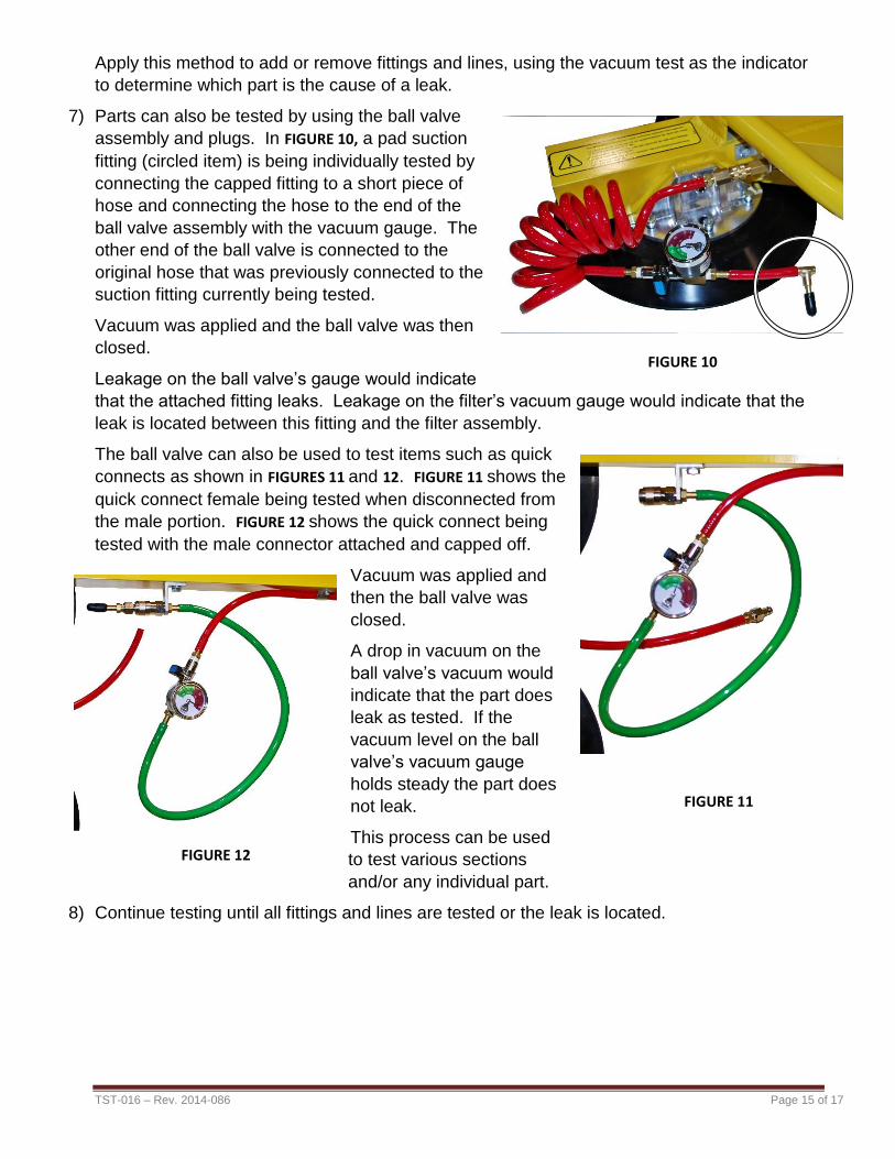
7) Parts can also be tested by using the ball valve
assembly and plugs. In FIGURE 10, a pad suction
fitting (circled item) is being individually tested by
connecting the capped fitting to a short piece of
hose and connecting the hose to the end of the
ball valve assembly with the vacuum gauge. The
other end of the ball valve is connected to the
original hose that was previously connected to the
suction fitting currently being tested.
Vacuum was applied and the ball valve was then
closed.
Leakage on the ball valve’s gauge would indicate
that the attached fitting leaks. Leakage on the filter’s vacuum gauge would indicate that the
leak is located between this fitting and the filter assembly.
The ball valve can also be used to test items such as quick
connects as shown in FIGURES 11 and 12. FIGURE 11 shows the
quick connect female being tested when disconnected from
the male portion. FIGURE 12 shows the quick connect being
tested with the male connector attached and capped off.
Vacuum was applied and
then the ball valve was
closed.
A drop in vacuum on the
ball valve’s vacuum would
indicate that the part does
leak as tested. If the
vacuum level on the ball
valve’s vacuum gauge
holds steady the part does
not leak.
This process can be used
to test various sections
and/or any individual part.
8) Continue testing until all fittings and lines are tested or the leak is located.
FIGURE 10
FIGURE 11
FIGURE 12
TST-016 – Rev. 2014-086 Page 16 of 17
SYSTEM CONFIRMATION
Once all leaks are identified and repaired, reassemble all parts of the lifter.
The Vacuum Test, as described in the instruction manual, should be performed following any
repair or service to a vacuum lifter.
Note: On lifters with quick connects installed, a second vacuum test should be performed with
all quick connects disconnected. All parts must be verified in relation to their function and the
lifter must pass the Vacuum Test before returning the lifter to operation.
TST-016 – Rev. 2014-086 Page 17 of 17
ADDITIONAL INFORMATION
NOTES:
1) When requesting information on a particular lifter please have model number and serial
number information available in order for us to properly identify components.
2) CAUTION: Always proceed with caution when opening enclosures containing electrical
wiring.
Wiring is often connected to components in the cover, as well as the enclosure itself.
3) In some cases a leak may be identified to be in an assembly (such as in a filter or valve
assembly) but the actual cause is not apparent (neither the filter nor valve itself are the
cause). In these cases, it may be a cracked fitting. Cracks in fittings may be visible, but
often are virtually impossible to locate except under factory test conditions; they will often
appear as a dark line along the seam of female fittings, along the hex nut section of
female hose nipples, or at the base of the threads on male fittings. If a leak is traced to an
assembly and the cause is not visibly apparent it may be best to replace the whole
assembly rather than a single component.
4) If any metal fittings are disassembled during testing, always apply thread sealant (Teflon
tape or similar product) to the male threads prior to reassembly, to avoid vacuum leaks.
For plastic fittings use only Teflon tape; liquid sealants must not be used on plastic parts
and may damage the parts.
5) When assembling fittings do not over tighten. After first applying adequate thread sealant
or tape, the fitting is finger tighten as much as possible.
A straight fitting is tightened no more than two additional revolutions with a wrench.
An elbow fitting is tightened no more than one and a half additional revolutions with a
wrench
Once an elbow or tee fitting is tightened with a wrench, the fitting is aligned in the
clockwise direction with a wrench
6) Please note: The information that is gathered when performing a vacuum test is only
valid if the tools used to perform the test are accurate. Be sure that the tools you use are
capable of completely sealing your system.
If needed test equipment is available from Wood’s Powr-Grip Co.
There are various ways to approach testing vacuum lifters.
For further suggestions or information, please contact our staff at:
Wood’s Powr-Grip Co., Inc. 908 West Main
Laurel, Montana 59044 800.548.7341 406.628.8231
406.682.8354 (fax)
www.WPG.com
ALL LIFTERS MUST BE TESTED AFTER MAINTENANCE. SEE
INSTRUCTIONS FOR ADDITIONAL INFORMATION