leaders in m a r c h 2 0 1 3 locking tiles · • felt-tip marker/paint marker to mark tiles for...
TRANSCRIPT

Leaders inLocking Tiles M A R C H 2 0 1 3
- 1 -
Tools & Consumables
Like any job, your SofTILE® AP installation will go much smoother with the proper tools. The following list of tools and consum-ables are recommended for your upcoming project:
• Broom
• Leaf blower
• Aluminum straightedge 30 inch minimum - black lettering
• 24 inch square and speed square – yellow or white lettering
• Measuring tape - Imperial measurement units
(Tiles are made to Imperial measurements)
• Felt-tip marker/paint marker to mark tiles for cutting (Sharpie™
– metallic silver or equal)
• Templates – for marking postholes for cutting
• Polyurethane expansion foam
• Duct or masking tape to protect adjacent items during adhesive
application
• Disposable rags and/or paper towels (adhesive clean up)
• Goof Off® (red can), made by Valspar
• Cordless 18 V Albion deluxe adhesive dispenser for 20 ounce
sausage tube for tile-to-tile adhesive - part No. 1007-1E(SOF)
- SofSURFACES® custom nozzel for adhesive injection
- Recommend an additional dispenser
• Single barrel manual caulking gun for 20 oz (by volume) tubes to
dispense adhesive (Albion™ DL-45-T18 with Hytrel plastic piston)
- Cone nozzels
• V-Notched trowel with 1/8 inch square notch or 3/16 v notch
- plastic or metal trowel - for tile to base adhesive spreading
• 8 lb. sledgehammer
• Pipe Fittings (3/8 inch), for glue gun
Personal protective equipment
• Disposable protective gloves (latex, nitrile or other) - for
adhesive application
• Gloves (general work gloves)
• Safety glasses
• Hard hat
• Knee pads
Optional equipment
• Vacuum cleaner
• Hot box - for heating of adhesive
• Flex curve carpenter
Introduction
SofTILE® AP are suitable for use as an architectural pavers on patiosand terraces. Other products and installation manuals are availablefor other applications.
The SofTILE® AP are suitable for use as an overlayment for mostconventional roofing systems, including built-up and single plymembrance products.
The locking feature, coupled with resiliency and color diversity are the unique benefits that have positioned SofTILE® AP as the prefer-red product for rooftop ballast and architectural paver applications.
SofTILE® Architectural Paver system has been designed to be installedusing specific installation methods developed to ensure the long-term performance of the surface. Each step in the installation processis critical to ensure a successful installation. This manual has been designed utilizing the best installation techniques taken from various professional SofTILE® AP installation crews across North America. The manual was designed to ensure that the SofTILE® AP surface has been installed according to specification and has also incorporatedthe most efficient methods of installation.
INSTALLATION GUIDE
• Chalk line & refill bottle (black is permanent)
• String line
• Heavy-duty auto-lock cutter utility knife (Olfa LA-X™ or equal)
& replacement blades (LBB UltraMax™ or equal)
• Jigsaw (Bosch or equal - minimum 5.5 amp or greater
recommended)
• Jigsaw blades; 10 teeth per inch minimum
- Should be not any longer than 1/4 inch shorter than the
thickness of tile (in saw and when extended)
Site Survey
Note: Insufficient drainage will result in the SofTILE® AP surface being subjected to standing water for long periods of time. Standing water will damage the SofTILE® AP surface and void the warranty.
DRAINAGE IS REQUIRED

- 2 -
The Layout
When preparing the initial site layout there are important factors to
take into consideration:
• Each SofTILE® AP tile is manufactured to a nominal dimension
of 24.2” (+/- 1/16th“) x 24.2” (+/- 1/16th“) from the factory
• The SofTILE® AP installation process requires that each tile be in-
stalled under compression to a finished dimension of 24”
• A site typically requires fixed edges. This may take the form of
buildings, sidewalks, plant boxes, glued-down SofRAMPs®, etc.
• It is unlikely that the site is perfectly square or exactly as shown in
the drawings
• The glueless SofTILE® AP installation method requires that all
perimeter tiles be cut in at the beginning of the installation.
To ensure a visually proportionate site, lay the surface out with similar
dimension cuts on all four sides of the area. When possible, cut tiles should be a minimum of 10” in width. Check the preparedsite tile layout drawing.
INSTALLATION METHOD ONE - Partial Glue Down Method (Applications Larger Than 2,000 sq.ft.)
Each SofTILE® AP tile measures approximately 24.2” (+/- 1/16th“)
x 24.2” (+/- 1/16th“) from the factory.
After they are installed under compression they must measure
24” X 24“ meaning each tile must be compressed by a minimum
of 1/8th inch.
Since each individual SofTILE® AP tile must be compressed by 1/8th
inch, the cumulative compression over a large area can best be
achieved by breaking the total area into smaller more workable grid
sections.
Fig. 1
42’
42’
Horizontal Center Line
Vertical Center Line
The following guidelines have been prepared to ensure that your
large installation is properly compressed using a minimal amount
of effort. This advanced installation technique will introduce new
terminology and concepts involving the use of keystone tiles,
strategic rows of tiles and compression rows. Fig. 2
Chalk Control Lines24”
Note: A properly designed and installed water collection system is often overlooked during SofTILE® AP site planning stages. Although the tiles are impervious, water will pass through the corners and seams of the SofTILE® AP system. It is critical that a proper subsurface drainage system be installed. A - Locate the Center Line of the Area
Locate, measure and chalk line the vertical and horizontal center lines in the area. Center lines should be shifted based on the best visual effect on the perimeter cuts. When possible perimeter cuts should be a minimum of 10 inches in width (Fig. 1).
Note: The installation techniques outlined in the following sections are mandatory to ensure the surface has been installed to specification and to validate the warranty.
In some instances additional surface water drainage is required and
tiles may require holes drilled through them. Drill holes between the
pedestals approximately a 1/2 inch in diameter. Holes do allow for
dirt access. Tiles with drilled holes in them are not covered by the
replacement warranty.

- 3 -
B - Striking LinesFrom the center point in the area strike chalk lines in 24 inch increments across the area in both directions so that a grid pattern has been created across the entire area (Fig. 2).
Fig. 3
Keystone Tile
C - Install Keystone Tiles Tiles that are permenantly fastened to the subsurface in strageic locations throughout the installation are referred to as keystone tiles.Keystone tiles are fastened to the sub-surface using the adhesive supplied with the order. See adhesive section at the back of the book for detailed instructions. The purpose of keystone tiles is to providea fixed point of compression for the strategic tile rows. Using the adhesive method at the back of the book, adhere key-stone tiles in each of the four corners of the installation. Since perimeter cuts can be placed last, each keystone tile should re- present a full tile (Fig. 3).
Continue to place and secure keystone tiles every 7th tile through-out the installation (6 tiles spaces between keystones tiles) (Fig. 4).
D - Install Strategic Tile Rows Strategic rows of tiles are compressed between the keystone tiles.Installation of strageic rows assists in breaking large sites into smaller areas that are much easier to compress into place. a) Begin by trowelling the factory supplied adhesive in a 12” x 12“ square centered where each tile will be placed. See adhesive instructions in back of manual.
b) Install strategic rows of tiles beginning at opposite ends of the keystone tiles working inwards towards the center (Fig. 5).
Fig. 5
Keystone Tiles
Work inward towardsthe center
Strategic Rows
Fig. 4
Note: Keystone tile adhesive must cure enough to prohibitmovement before strategic tiles rows are placed. Average set time is 4 hours based on temperature and humidity.
d) The locking mechanism on each edge of the tile should be en- gaged with the adjacent tile forcing the tile to buckle upwards. Once the locks are engaged, force the tile flat by applying down- ward pressure onto the tile (Fig. 7).
e) The tile must be compressed into each strategic row within the adhesive working time to ensure the tiles are able to move before the adhesive cures.
c) The final tile located in the middle of the strategic row is the compression tile and must be compressed into a space smaller than the tile. The process of compressing the tile into this space will force the other tiles to compress in each direction (Fig. 6).

- 4 -
E - Install Compression RowsFig. 6
CompressionTiles
Apply DownwardPressure
Fig. 7
Fig. 8
Compresssion Rows
11 1/16”
11”
Fig. 10
Fig. 9
Field Tiles
Compression rows are defined as the rows of tiles installed in thecenter of the strategic rows forming a cross hair in the center of each grid. Compression rows are installed before the remaining field tiles are installed. Compression rows of tiles are not adhered to the floor. Compression rows must be installed after the strategic row adhesive has cured (Fig. 8).
F - Installing Field TilesThe remaining tiles to be installed are referred to as the field tiles.Install field tiles according to the diagram shown in Fig. 9.
Fig. 11
Perimeter Cut Tiles Start in the Corners
G - Cutting in the PerimeterAt each seam location along the chalk line around the perimeter of the room, measure the distance from the perimeter tile edge to the wall and add 1/16” to this measurement. Transfer these measure-ments onto the tile (Fig. 10).
- 5 -
Cut tiles with a razor blade knife and metal straight edge on the linebut with a back-cut or under-cut of approximately 5 degreesInstall the cut tiles all the way around the perimeter. Start at thecorners and work around (Fig. 11).
H - Transitional Ramp InstallationIf transitional ramps are being utilized on one or more sides they must be permanently secured to the sub-surface using the adhesive application method below.
ADHESIVE INSTRUCTIONS Depending on the size and scope of your project different adhesives may be supplied with the order: • Sika 221 is supplied for installations that require less than 2 gallons of adhesive. Sika 221 is supplied in 600 ml sausage tube format and will need to be dispensed using the adhesive gun supplied with the order. • Greenfusion is supplied on installations that require more than 2 gallons of adhesive. Greenfusion is supplied in 4 gallon pails. Transitional Ramp Adhesion Prior to beginning the adhesive application process, measurements should be verified to ensure that the transitional edge pieces are placed in the exact position required based on the compression table and floor layout.
Adhere transition pieces by placing the manufacturer supplied adhesive between the transition edge and sub-floor. If using Sika 221, begin by dispensing several large beads of adhesive from the tube onto the subsurface.
Finish the adhesive using a 1/8th inch square notched trowel to obtain 100% coverage.
Once the transition ramp has been placed over the adhesive, itshould be allowed to fully cure before any compressive force is placed on it.
Fig 11c12”
Fig. 12
12”
Keystone and Strategic Tile Row Adhesion Prior to adhering any tiles check the drawing to ensure that the installed tiles represent the intended design.
Ensure that the control lines have been properly marked based on the attached compression chart.
Recommended Trowles For Maximum Performance
1/8” x 1/8” x 1/8” - Coverage 45 ft2 per Gallon
• Trowel size is suggested to maximize coverage of adhesive. Periodically check coverage of adhesive during installation. Uneven surfaces may require the use of either a leveling/ patching material, or a larger notched trowel for proper coverage of adhesive.
1/8”
1/8” 1/8”
A - Locate the Center Line of the AreaLocate, measure and chalk line the vertical and horizontal center lines in the area. Center lines should be shifted based on the best visual effect on the perimeter cuts. When possible perimeter cuts should be a minimum of 10“ in width (Fig. 1).
This method was developed for installations where you are unable to glue to the sub-surface. Please check with the manufacturer or supplier of the roofing membrane for approval to install tiles with or without a protective layer.
Each SofTILE APTM tile measures approximately 24.2” (+/- 1/16th“) x 24.2” (+/- 1/16th“) from the factory.
After they are installed under compression they must measure 24” X 24” meaning each tile must be compressed by a minimum of 1/8th inch.
Fig. 1
42’
42’
Horizontal Center Line
Vertical Center Line
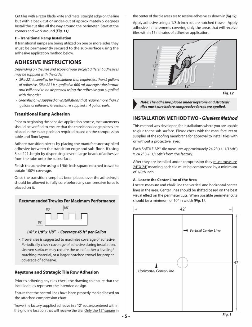
the center of the tile areas are to receive adhesive as shown in (Fig. 12).
Apply adhesive using a 1/8th inch square notched trowel. Apply adhesive in increments covering only the areas that will receive tiles within 15 minutes of adhesive application.
Note: The adhesive placed under keystone and strategic tiles must cure before compressive forces are applied.
INSTALLATION METHOD TWO - Glueless Method
Trowel the factory supplied adhesive in a 12" square, centered within the gridline location that will receive the tile. Only the 12" square in

- 6 -
Transfer these measurement onto the tile.
Cut tiles with a razor blade knife and metal straight edge on the line but with a back-cut or under cut of approximately 5 degrees.Install the cut tiles all the way around the perimeter. Start at the corners and work around the area.
Perimeter tiles should be installed in 6 tile increments leaving a one tile space between each 6 tile row. This is done to make com-pression easier by balancing the compressive forces throughout the floor (Fig. 3).
Compress the final perimeter tiles into the remaining voids (see ‘G’ for further details).
D - Transitional Ramp InstallationIf transitional ramps are being used on one or more sides they must be permanently secured to the floor in order to provide a fixed point of compression for the field tiles. Prior to the installation of field tiles, locate the final position of the transitional ramps based on the attached Compression Chart and fix them in place with the
Fig. 3
Perimeter Cut Tiles Start in the Corners.
Fig. 4
B - Striking LinesFrom the center point of the area strike chalk lines in 24” incre-ments across the area in both directions so that a grid pattern has been created across the entire area (Fig. 2).
C - Cutting in the PerimeterIn order to properly compress all of the field tiles, the perimeter of the area must be cut in and placed first.
At each seam location along the chalk line around the perimeter of the area, measure the distance from the line to the wall and add 1/16“ to this measurement and write that dimension on the floor.
Continue this process at every seam around the perimeter of the area (every 24”).
Fig. 2
Chalk Control Lines24”
adhesive supplied with the order. Adhesive must be fully cured before compression can be applied to the transitional edge (see adhesive instructions for additional information).
E - Installing Field Tiles Install the field tiles running in one direction only across the area. Install every other row of tiles only beginning at the perimeter cuts at each end of the area.
Tile rows should be installed in approx 6 tile increments leaving a one tile space between each 6 tile row. The number of tiles between spaces may need to be adjusted based on the area dimensions. (Fig. 4).
- 7 -
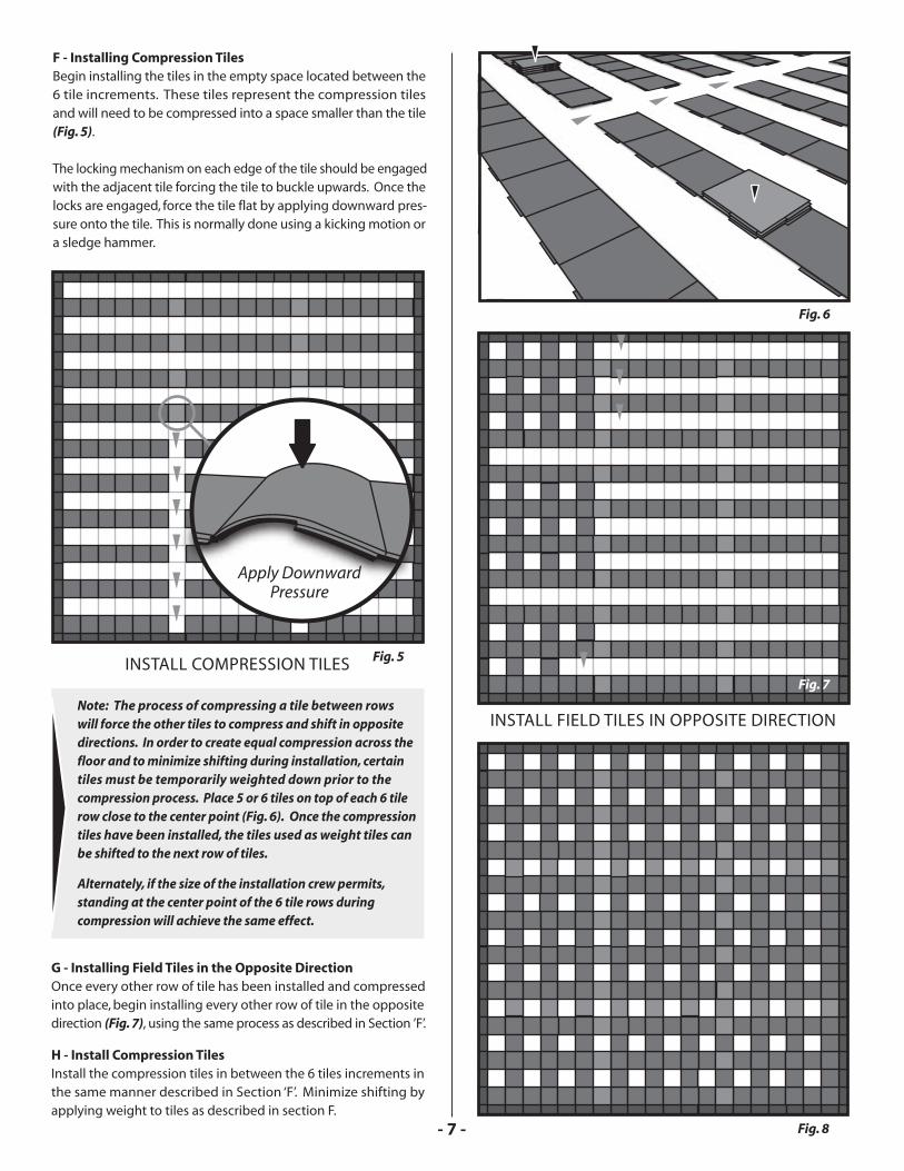
INSTALL FIELD TILES IN OPPOSITE DIRECTION
Fig. 7
Fig. 8
G - Installing Field Tiles in the Opposite DirectionOnce every other row of tile has been installed and compressedinto place, begin installing every other row of tile in the opposite direction (Fig. 7), using the same process as described in Section ’F’.
H - Install Compression TilesInstall the compression tiles in between the 6 tiles increments in the same manner described in Section ‘F’. Minimize shifting by applying weight to tiles as described in section F.
Fig. 6
Note: The process of compressing a tile between rows will force the other tiles to compress and shift in opposite directions. In order to create equal compression across the floor and to minimize shifting during installation, certain tiles must be temporarily weighted down prior to the compression process. Place 5 or 6 tiles on top of each 6 tile row close to the center point (Fig. 6). Once the compressiontiles have been installed, the tiles used as weight tiles canbe shifted to the next row of tiles.
Alternately, if the size of the installation crew permits, standing at the center point of the 6 tile rows during compression will achieve the same effect.
F - Installing Compression Tiles Begin installing the tiles in the empty space located between the 6 tile increments. These tiles represent the compression tiles and will need to be compressed into a space smaller than the tile(Fig. 5).
The locking mechanism on each edge of the tile should be engaged with the adjacent tile forcing the tile to buckle upwards. Once the locks are engaged, force the tile flat by applying downward pres-sure onto the tile. This is normally done using a kicking motion or a sledge hammer.
Fig. 5INSTALL COMPRESSION TILES
Apply DownwardPressure

- 8 -
STEP TWOOnce all of the tiles around the perimeter have been partially installed by engaging the corners, begin compressing the tiles into place. Compressing the tiles can be labor intensive and is best accomplished by applying considerable downward force through a kicking action and the use of a sledge hammer. Continue this process throughout the area using the two step method above. Install final compression tiles in large groups at a time, beginning with the one or two rows around the perimeter and then working throughout the surface area (Fig. 11).
Fig. 10
Fig. 11
I - Placing Final CompressionAt this point in the installation your tile layout should look like the drawing shown in Fig. 8.
The remaining spaces in the floor are smaller than the tiles that will be placed and therefore each tile must be forced into place. The process of forcing each remaining tile into place will compress all of the remaining tiles in opposite directions.
STEP ONEBegin by engaging the locks in each of the four corners with the tiles adjacent. This process will create significant pressure and will cause the compression tile to balloon (Fig. 9).
Starting on the outer perimeter rows, continue to engage the four corners of each compression tile without attempting to compress the tiles (Fig. 10).
Fig. 9
Compress tiles throughout the remainder of the area based on how the tiles are shifting during installation.
Cutting Tiles
Most straight cuts can be made with a utility knife. When using autility knife place the tile on a level surface and score the area to becut with an initial pass of the knife. Once the score has been made,apply pressure to the tile to open the score. Placing the tile over a 2x4or allowing the edge of the tile to hang over a table top will assist in opening the score. Opening the score of the tile reduces friction between the tile and the knife making the cut much easier. Continue making passes with the knife working your way through the tile. A jigsaw can also be used to make straight and irregular cuts. When using a jigsaw, always score the tile with a utility knife or circular saw first.
All cutting should be done in a 15-20 degree back angle. Always usea jigsaw blade that is 1/4 inch shorter than the thickness of the tile. It is easiest to cut tiles when the tile is laying flat on a stable surface.
Adhering Tiles
SofTILE® AP’s unique locking design provides a mechanical means of securing the system. The locking system, however was engineered to be effective only when installed with the proper quantity and placement of adhesive.
Key points • Proper application of adhesive to the KrosLOCK joint is critical to the overall performance of the SofTILE® system and is man- datory for all outdoor applications. • Using too little adhesive, or applying the adhesive in the in- correct location will result in failure of the locking system, and will void the warranty.

- 9 -
1. Checklist prior to applicationPrior to beginning the adhesive application process, the following checklist should be verified. Any corrections that need to be made will be much easier prior to the application of adhesive. • Check your layout and the drawings to ensure that your installation represents the intended design, check that all of your rows are straight, and that all of the seams are properly aligned. • Ensure that the surface has been compressed to the correct dimension. • Make sure your perimeter and post cuts are tight and neat. • Verify that the tiles are clean and dry.
• Only use adhesive provided by or recommended by the manu- facturer. • Only use the application equipment provided by the manu- facturer. • Sealing the entire length of the seam will prevent damage caused by the migration of sand and other loose particles into the seams of the product. • Surface temperatures above 40 degrees F and rising are recom- mended. Avoid temperatures below 40 degrees F and above 105 degrees F. • Surfaces must be clean and completely free of moisture, morning dew, or frost. • Adhesive heated to 75-80°F.
2. Adhesive placement locationsAdhesive application methods vary slightly depending on the typeof installation and the substrate that the system will be placed on. Regardless of the substrate used however, all SofTILE® systemshave minimum adhesive application requirements. 3. Tile to tile adhesionTile to tile adhesive must be properly placed on the vertical wallof the interlocking joint and NOT in the bottom of the u-shapedlocking system (Fig 10a).
Placing the correct amount of adhesive onto the proper location of the product will ensure the long term success of the installation.
4. Preparing the equipment In order to minimize any potential mess during adhesive application, a small set up area should be created using a piece of cardboard
Side View Front View Back View
or other disposable covering material. Prior to beginning the adhesive application process, make sure you have rubber gloves, rags, a knife and appropriate cleaning solutions for clean up purposes (see page 1). a) Open the dispensing unit by unscrewing the tip and cap.b) Pull the notched dispensing arm out to accomodate the adhesive tube.c) When inserting the adhesive tube, leave 3-4 inches exposed.d) Using scissors or a knife cut the entire tip off the tube, and discard the end.e) Hold the dispensing unit upright to allow the tube to slide entirely into the unit.f) Assemble the tips and cap ensuring that they are tightly screwed into each other and the dispensing unit.
Fig 10b
5/8”
5. Application nozzles You will notice that the adhesive application tip has been customdesigned for use with the KrosLOCK system (Fig 10b).The tip has been designed to control both the depth and placementof the adhesive. Although the tip has been designed to minimizeseepage, careful attention must be paid to ensure that the correct amount of adhesive is being applied. Too little adhesive will affect the performance of the locking system. The correct amount of adhesive will rise to flush with the seam lines.
Area of Adhesive ApplicationSofTILE
InterlockingChannel
Fig 10a
ADHESIVE LOCATION
6. Adhesive application techniques
• Adhesive is to be heated to 75-80°F prior to use. • Insert the custom applicator tip into the seam of the tiles until the depth guide (washer), comes in contact with the top of the tiles (Fig 10c). • Do NOT move tip until adhesive begins dispensing. • Begin applying the adhesive between the tiles ensuring that the appropriate amount of adhesive is being applied to each tile. If adhesive begins to seep from the seams of the product adjustments will need to be made to your pressure and speed. • The ideal quantity of adhesive will provide sufficient contact to both sides of the tile and will rise flush with the top of the seamline. • As a general guideline select the 2.5 to 3.0 setting on the power dispenser and start with a travel speed of one tile length every 5 seconds. • Adhesive coverage must always be verified by measuring against the recommended coverage of 40 lineal feet per tube. • Since adhesive flow rates can be affected by temperature adjustments to travel speed may be needed based on the actual adhesive coverage achieved.

- 10 -
Fig 10c
Fig 10d
Fig 10e
take place in both directions representing the length and width
of the site within a short time period of each other.
• Under no circumstances should a SofTILE® AP system be installed
outdoors without the use of adhesive.
• All adhesive supplied with the order should be completely
consumed.
• Any excess adhesive should be left to fully cure prior to removal
the following day. The excess adhesive can be quickly and neatly
removed using a sharp razor knife.
Key Points
• When removing the tip from the seam be sure to have a rag
available. Twist and wipe tip while removing.
• Apply adhesive to an entire row at a time, keeping track of the
rows you have completed (chalk mark, etc.).
• Always mark the last location where adhesive was placed
prior to refilling adhesive gun.
• To prevent blockage from cured adhesive, the application should
Fig 11c12” Fig 11b
7. Transitional edging adhesionWhen a SofRAMP® transitional edge piece is used, adhesive must be
placed both between the tile and SofRAMP®, and between each
SofRAMP® edge using the applicator tip. Adhesive will also be
placed between the SofRAMP® and subsurface using the manu-
facturer supplied subsurface adhesive and a notched trowel
(Fig 11b).
SofRAMP® perimeter edging is adhered to the subsurface using
the perimeter to subsurfaces adhesive supplied with the order.
Care must be taken to ensure that the adhesive does not seep outside
of the coverage area which in some cases may requiring taping.
SofRAMP® perimeter edging is adhered to the tile using the same
procedure as tile to tile adhesion (Fig 11c)
SofRAMP®SofTILE® AP
Fig 11c
Adhesive
8. Post cutsAdhesive must be applied to the initial straight cut leading into thecircular cut (Fig 11d).

- 11 -
Fig 11d
Equipment Post
Adhesive to be applied to the initial straight cut leading into the circular cut.*
*
SofTILE® AP
9. Adhesion under decksSome areas of the site, such as under low elevation decks will be impossible to adhere using the applicator tip. In these instances, adhesive must be placed on the vertical wall of the locking jointprior to positioning the tile in place.
Fig 11e
area will need to be protected so the area is not walked on. After curing you will need to use a knife to “scrape” the bead off of the tile.
2. Initial appearance and maintenance
Solid SofTILE® AP colors will behave like new carpets when initially installed. The solid, brilliant colors will make the initial dust created by foot traffic very apparent. However, with time, the visible dust tracking will diminish.
3. Initial odor
The polyurethane used to bind the rubber granules is 100% inert and odorless after it has fully cured. Full curing can take up to several days depending on atmospheric temperature and moisture. The odor may take longer to dissipate on indoor applications because of the confined area. The rubber may also have an odor.
4. Sealant
It is SofSURFACES’® recommendation not to apply sealants to any SofTILE® AP surface. However should you have any questions about sealing or coating the surface of the SofTILE® AP product please contact our office.
Routine Maintenance
1. Routine maintenance extends life and enhances appearanceLike any surface, a good routine maintenance program will enhance the longevity and appearance of the SofTILE® AP surface.
2. Regular cleaningSweeping or blowing the surface off with a leaf blower shouldbe done regularly to ensure that abrasive materials, such as sand,are removed from the SofTILE® AP surface.
3. VacuumPeriodic vacuuming is recommended in areas where sand is fre-quently tracked onto the surface.
4. Cleaning agentsSofTILE® AP can accommodate moderate use of most household or commercial cleaners that contain both odor suppressants anddisinfectants. Dilute this cleaning agent as recommended by the manufacturer. Apply to the surface using a mop or scrubbing device. This will remove most light stains. Use only pH neutral based cleaning agents that do not contain bleach, or citrus.
Advanced Maintenance
Depending on frequency of use, SofTILE® AP will occasionally need a “deep clean” to remove built up dirt and stains.
For most decks you can use a modified extension on the glue gun as shown in Fig 11e.
Final Installation Details
1. Remove any adhesive spills
a) “Smeared” adhesive spill
If a small amount of adhesive is spilled onto the surface during installation, this can be removed immediately by wiping the
1. Steam vacuumA steam vacuum with or without cleaning agents is ideal for advanced cleaning and maintenance. Follow instructions.
2. Power washingIn areas that can accommodate power washing, use a power washer with a wand tip. Wand tip should be kept a minimum of 8 inches from the surface to prevent damage.
(red can), or other suitable solvent. Use proper handling pro- cedures. Try to “lift” the adhesive if possible from the surface.
b) “Bead-shaped” adhesive spill If any adhesive inadvertently drips out of the end of the caulking tube onto the SofTILE® AP surface, and this adhesive lies on the tile in a convex shaped bead, with extreme caution it can be lifted immediately (do not smear) with a cloth or knife. If unable to lift it should be removed only after it has partially cured. The area will need to be protected so the area is not walked on.
spot with a rag containing a small amount of WD40, GoofOff
- 12 -
Summary
• Proper application and quantity of adhesive to the KrosLOCK
joint is critical to the overall performance of the surfacing system.
• Only use adhesive provided by or recommended by the manu-
facturer.
• Protective gloves should be worn to prevent skin contact.
• Take caution to ensure that adhesive is not spilled on adjacent
surfaces.
• All adhesive supplied with the order should be completely
consumed at the end of the installation.
Closing Statement
The entire SofSURFACES’® team wishes to thank you for your careful
consideration and decision to purchase a SofTILE® AP system.
Your investment in a SofTILE® AP system is a wise one.
We work hard to produce the highest quality products and our
dedication to customer service does not end with the sale of our
surfacing. As industry leaders we are committed to the long-term
success of your project.
We are available by phone at 1-800-263-2363 from 8:00 am to
5:00 pm Monday through Friday.
Thank you for your confidence.
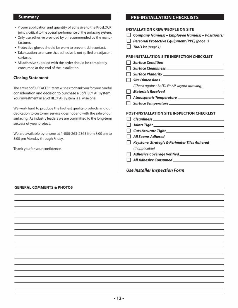
POST-INSTALLATION SITE INSPECTION CHECKLIST
Cleanliness
Joints Tight
Cuts Accurate Tight
All Seams Adhered
Keystone, Strategic & Perimeter Tiles Adhered
(If applicable)
Adhesive Coverage Verified
All Adhesive Consumed
Use Installer Inspection Form
PRE-INSTALLATION CHECKLISTS INSTALLATION CREW/PEOPLE ON SITE
Company Name(s) – Employee Name(s) – Position(s)
Personal Protective Equipment (PPE) (page 1)
Tool List (page 1)
PRE-INSTALLATION SITE INSPECTION CHECKLIST
Surface Condition
Surface Cleanliness
Surface Planarity
Site Dimensions
(Check against SofTILE® AP layout drawing)
Materials Received
Atmospheric Temperature
Surface Temperature
GENERAL COMMENTS & PHOTOS

1 of ___
INSTALLATION INSPECTION FORM
Facility or Site Name: Inspection Date/Time:
Address:
Installation Date(s) & Weather Conditions:
Installation Company: Crew Leader:
Dealer: Customer:
� • Include list of all installation team members on site� • Include photos of before, during, and after installation
1. SUB-SURFACE & EDGE CONDITIONS
Sub-Surface Type Detail - Please record actual detail; may include membrane type, concrete, wood, etc.
Edge Type Detail - Please record actual detail; may include wall, parapet, curbing; concrete, wood, etc.
2. SITE CONDITIONS - Installation
Tiles and Joints are Straight . . . . . . . . . . . . . . . . . . . . . . . . . . . . . .
Cuts Accurate and Tight
Around Posts . . . . . . . . . . . . . . . . . . . . . . . . . . . . . . . . . . . . . . . . .
Around Drains . . . . . . . . . . . . . . . . . . . . . . . . . . . . . . . . . . . . . . . .
At Curbs . . . . . . . . . . . . . . . . . . . . . . . . . . . . . . . . . . . . . . . . . . . . . .
Tiles Installed Under Compression (at 2 foot per tile) . . . . . .
(Measure distance across 15 to 20 tiles in numerous locations and directions)
3. ADHESIVE
All Joints Adhered 100% - Level to Base of Bevel . . . . . .
All Edges and Cuts Adhered 100% . . . . . . . . . . . . . . . . . . . . .
Excessive Adhesive Removed/Trimmed . . . . . . . . . . . . . . . . . .
All Adhesive Supplied with Order Completely Consumed
4. SECURE SURFACES
Edges Secure and Firm . . . . . . . . . . . . . . . . . . . . . . . . . . . . . . . . . . .
At Posts Secure and Firm . . . . . . . . . . . . . . . . . . . . . . . . . . . . . . . . .
Ramps Secure . . . . . . . . . . . . . . . . . . . . . . . . . . . . . . . . . . . . . . . . . . . .
5. SITE CONDITIONS - General (when finished)
Cleanliness of Site . . . . . . . . . . . . . . . . . . . . . . . . . . . . . . . . . . . . . . . .
Yes No COMMENTS
I hereby certify that the above areas are either in good working condition or deficiencies have been forwarded to the appropriate office.
Customer:
Site Installer:
Print Name
Print Name
Signature
Signature
SEND COPY TO SofSURFACES® AT 1.519.882.2697
•� Record temperatures and weather each day while on site� • Record any site issues and how they were resolved
Remaining Tubes: Pails:

2 of ___
Facility or Site Name: Inspection Date/Time:
INSTALLATION INSPECTION FORMSEND COPY TO SofSURFACES AT 1.519.882.2697®
Installer(s) List: Certified:
1.
2.
3.
4.

Leaders inLocking Tiles J A N U A R Y 2 0 1 3