lcls wbs dictionary lclb r4-031209 · lcls wbs dictionary l1 l2 l3 l4 l5 ca 1 1 lcls project - ped...
TRANSCRIPT

LCLS WBS DICTIONARY
L1 L2 L3 L4 L5 CA1 1 LCLS PROJECT - PED & CONSTRUCTION This summary WBS covers the Total Estimated Cost (TEC)
Estimate for the LCLS Project being constructed at SLAC. The LCLS TEC is supported through Project Engineering and Design (PED) and Construction funds by the U.S. Departmentof Energy.
1 01 101 LCLS PROJECT MGMT, PLANNING & ADMN (TEC) This summary WBS covers the project management, planning and organization function of the PED and construction phases (TEC) of the LCLS Project.
1 01 01 10101 Environment, Safety & Health This summary WBS describes the ES&H support for the LCLS project at SLAC.
1 01 01 01 1010101 Radiation Physics This WBS supports radiation physics experts/consultants to facilitate the LCLS shielding and enclosure designs and in conducting periodic radiation safety reviews on the LCLS project.
1 01 01 02 1010102 ESH Management & Coordination This WBS supports ES&H staff/consultants who provide support to the line management for the LCLS Integrated Safety Management System (ISMS)
1 01 01 03 1010103 Professional Services-Project Office Support This WBS supports seismic and engineering experts/consultants to provide seismic and/or engineering evaluations and reviews for the LCLS project.
1 01 02 10102 Project Management This summary WBS describes the project management function for the LCLS project at SLAC.
1 01 02 01 1010201 Project Management Office This summary WBS describes the LCLS Project Office at SLAC.
1 01 02 01 01 101020101 Project Office - General This WBS provides for the management function of the LCLS Project Office based upon the approved LCLS Organization Chart. This includes a Project Director, Deputy Project Director and 2 Associate Project Directors, 2 full-time Technical System Managers (E-Beam and Photon System Managers), 1 full-time Financial Analyst (Budget/Finance Manager), and 4 full-time Administrative Aides. In total,11 FTE's. The 11 FTEs are phased between TEC and OPC to reflect the average fraction of effort spent on construction and R&D/Pre-Operations/Operations.
1 01 02 01 02 101020102 Project Support This WBS provides for the support function of the LCLS Project Office, which includes: The LCLS Project Management Control System (PMCS) supported by a team of cost/schedule analysts that will establish and maintain a PMCS to track the planning, performance and resource allocation during the LCLS construction project. Additional collective duties include maintaining the Work Breakdown Structure (WBS), tracking and maintaining the cost and schedule baseline and documenting the Baseline Change Proposal (BCP) System.). Primavera is used as the primary scheduling tool and COBRA is used for cost analysis.
1 01 02 01 02 101020102 Project Support (continued) Website support for the LCLS project is provided by the Database Manager and includes maintaining the LCLS website as the primary repository of project information. The LCLS website will include a general area of information about LCLS (education, outreach, LCLS applications and future directions), technical areas for LCLS groups to disseminate information, and sensitive LCLS management information on costs, budgets, PMCS data (earned-value, change control). This area also includes a quality control manager as well as consulting support for the LCLS procurement activities.
1 01 02 01 03 101020103 Project Office M&S This WBS provides for the Materials & Supplies (M&S) for the LCLS Project Office, which includes: Miscellaneous M&S to operate the LCLS project on a day-to-day basis which includes all office supplies, binders, etc. to support the LCLS team. All M&S costs necessary to support the LCLS project during reviews (Management, Physics, Safety, Engineering, etc.) is included in this WBS. Tele/videoconferencing equipment (polycoms, monitors, phones, modems) and projector costs for the LCLS project, including setup labor. AllPC + software costs for the LCLS group. Miscellaneous shipping or storage of general LCLS items at SLAC.
WBS NUMBER
TITLE DESCRIPTION
LCLS_WBS_Dictionary_LCLB_r4-031209.xls Page 1 of 63
LCLS WBS DICTIONARY
L1 L2 L3 L4 L5 CA
WBS NUMBER
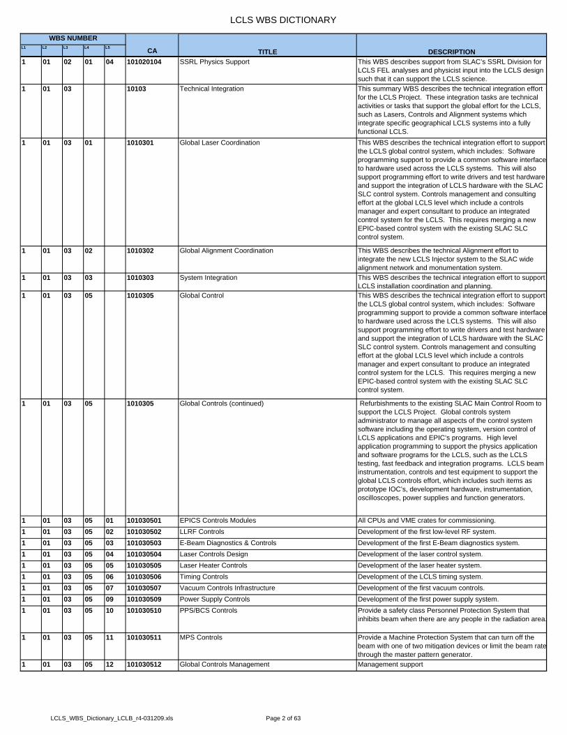
TITLE DESCRIPTION1 01 02 01 04 101020104 SSRL Physics Support This WBS describes support from SLAC’s SSRL Division for
LCLS FEL analyses and physicist input into the LCLS design such that it can support the LCLS science.
1 01 03 10103 Technical Integration This summary WBS describes the technical integration effort for the LCLS Project. These integration tasks are technical activities or tasks that support the global effort for the LCLS, such as Lasers, Controls and Alignment systems which integrate specific geographical LCLS systems into a fully functional LCLS.
1 01 03 01 1010301 Global Laser Coordination This WBS describes the technical integration effort to support the LCLS global control system, which includes: Software programming support to provide a common software interfaceto hardware used across the LCLS systems. This will also support programming effort to write drivers and test hardware and support the integration of LCLS hardware with the SLAC SLC control system. Controls management and consulting effort at the global LCLS level which include a controls manager and expert consultant to produce an integrated control system for the LCLS. This requires merging a new EPIC-based control system with the existing SLAC SLC control system.
1 01 03 02 1010302 Global Alignment Coordination This WBS describes the technical Alignment effort to integrate the new LCLS Injector system to the SLAC wide alignment network and monumentation system.
1 01 03 03 1010303 System Integration This WBS describes the technical integration effort to support LCLS installation coordination and planning.
1 01 03 05 1010305 Global Control This WBS describes the technical integration effort to support the LCLS global control system, which includes: Software programming support to provide a common software interfaceto hardware used across the LCLS systems. This will also support programming effort to write drivers and test hardware and support the integration of LCLS hardware with the SLAC SLC control system. Controls management and consulting effort at the global LCLS level which include a controls manager and expert consultant to produce an integrated control system for the LCLS. This requires merging a new EPIC-based control system with the existing SLAC SLC control system.
1 01 03 05 1010305 Global Controls (continued) Refurbishments to the existing SLAC Main Control Room to support the LCLS Project. Global controls system administrator to manage all aspects of the control system software including the operating system, version control of LCLS applications and EPIC’s programs. High level application programming to support the physics application and software programs for the LCLS, such as the LCLS testing, fast feedback and integration programs. LCLS beam instrumentation, controls and test equipment to support the global LCLS controls effort, which includes such items as prototype IOC’s, development hardware, instrumentation, oscilloscopes, power supplies and function generators.
1 01 03 05 01 101030501 EPICS Controls Modules All CPUs and VME crates for commissioning.1 01 03 05 02 101030502 LLRF Controls Development of the first low-level RF system.1 01 03 05 03 101030503 E-Beam Diagnostics & Controls Development of the first E-Beam diagnostics system.1 01 03 05 04 101030504 Laser Controls Design Development of the laser control system.1 01 03 05 05 101030505 Laser Heater Controls Development of the laser heater system.1 01 03 05 06 101030506 Timing Controls Development of the LCLS timing system.1 01 03 05 07 101030507 Vacuum Controls Infrastructure Development of the first vacuum controls.1 01 03 05 09 101030509 Power Supply Controls Development of the first power supply system.1 01 03 05 10 101030510 PPS/BCS Controls Provide a safety class Personnel Protection System that
inhibits beam when there are any people in the radiation area.
1 01 03 05 11 101030511 MPS Controls Provide a Machine Protection System that can turn off the beam with one of two mitigation devices or limit the beam ratethrough the master pattern generator.
1 01 03 05 12 101030512 Global Controls Management Management support
LCLS_WBS_Dictionary_LCLB_r4-031209.xls Page 2 of 63

LCLS WBS DICTIONARY
L1 L2 L3 L4 L5 CA
WBS NUMBER
TITLE DESCRIPTION1 01 03 05 13 101030513 SLC Aware IOC Design and implementation of the software to emulate the
SLC micro communication inside the EPICS IOC to allow the existing high level applications on SLC to be used for early commissioning and operation.
1 01 03 06 1010306 Technical Requirements/Parameters This WBS describes the Accelerator Physics effort to define and write the technical physics requirements documentation for the LCLS Injector.
1 01 04 10104 Education Support This summary WBS describes the education and outreach support for the LCLS project and LCLS scientific program.
1 01 04 01 1010401 Education/Outreach Travel This WBS provides education/outreach travel to support the LCLS project such as presenting lectures on the scientific merits of the LCLS and promoting Free Electrons Lasers (FEL’s) as scientific instruments.
1 01 04 02 1010402 Education/Outreach M&S This WBS provides education/outreach M&S (brochures, posters, CD's, etc.) to support the LCLS project and the scientific merits of the LCLS.
1 02 102 INJECTOR SYSTEM The injector generates the electron beam and accelerates it to135 MeV. This system includes the laser, optical transport, the electron gun, the accelerator sections, the solenoids and other magnets, the diagnostics including a diagnostic section at the end of the injector, the LCLS timing system, and the laser room. The interface to the Linac is at the downstream end of Dog Leg 1 (DL1), ending at the valve at the entrance tolinac section L1.
1 02 01 10201 Injector System Management & Integration At level 3 of the WBS the Injector System is divided into 17 discrete systems. Each of these systems can have multiple functional requirements that range from local and sub system,to Linac, LCLS project, and then SLAC. This section of WBS identifies these interdependencies, supports the establishment of consistent and hierarchical requirements, and supports systems that manage and integrate these efforts. Requirements and planning for Injector installation is covered in this section.
1 02 01 01 1020101 Injector System Integration This section provides engineering and design support for the entire Injector system. This section addresses common system requirements for the Injector Vault, Shielding Walls, and Linac Insertion areas.
1 02 01 01 01 102010101 Injector Region Integration This section provides engineering and design support for the entire Injector system. This section addresses common system requirements for the Injector Vault, Shielding Walls, and Linac Insertion areas.
1 02 01 01 02 102010102 Gun Area Integration This section provides engineering and design support for this specific sub assembly of the Injector system. The interfaces between this mechanical sub assembly and the Injector vault are reviewed and or addressed in this section.
1 02 01 01 03 102010103 Accelerator Area Integration This section provides engineering and design support for this specific sub assembly of the Injector system. The interfaces between this mechanical sub assembly and the Injector vault are reviewed and or addressed in this section.
1 02 01 01 04 102010104 Heater Area Integration This section provides engineering and design support for this specific sub assembly of the Injector system. The interfaces between this mechanical sub assembly and the Injector vault are reviewed and or addressed in this section.
1 02 01 01 05 102010105 Wall Area Integration This section provides engineering and design support for this specific sub assembly of the Injector system. The interfaces between this mechanical sub assembly and the Injector vault are reviewed and or addressed in this section.
1 02 01 01 06 102010106 Insertion Area Integration This section provides engineering and design support for this specific sub assembly of the Injector system. The interfaces between this mechanical sub assembly and the Injector vault are reviewed and or addressed in this section.
1 02 01 01 07 102010107 Spectrometer Area Integration This section provides engineering and design support for this specific sub assembly of the Injector system. The interfaces between this mechanical sub assembly and the Injector vault are reviewed and or addressed in this section.
LCLS_WBS_Dictionary_LCLB_r4-031209.xls Page 3 of 63

LCLS WBS DICTIONARY
L1 L2 L3 L4 L5 CA
WBS NUMBER
TITLE DESCRIPTION1 02 01 01 08 102010108 Drive Laser Integration This section provides engineering and design support for this
specific sub assembly of the Injector system. The interfaces between this mechanical sub assembly and the Injector vault are reviewed and or addressed in this section.
1 02 01 04 1020104 Injector System Integration Effort / M&S This element covers the costs over the entire Injector for materials and supplies through the PED and Construction phase of the project. Specific categories are identified; Travel,Computers, Cost Account Management, as well as general Management.
1 02 02 10202 Injector Controls Subsystem The injector controls system is to be an EPICS – Experimental Physics and Industrial Control System. The Injector control system must interface with the existing linear accelerator (LINAC) timing system. Local system control, at Sector 20, will be used for development through the commissioning phase of the project. Operational control will reside in the LCLS Main Control Center (MCC).
1 02 02 01 1020201 Personnel Protection Subsystem (PPS) This section covers the cost of designing a new Personnel Protection System (PPS) for the injector, and writing software to integrate the new EPICS Control system with this PPS control system.
1 02 02 02 1020202 Beam Containment Subsystem (BCS) This section covers the cost of designing a beam containmentsystem for the injector, and writing software to integrate the new EPICS Control system with the existing accelerator BCS control system.
1 02 02 03 1020203 Machine Protection Subsystem (MPS) This section covers the cost of designing and writing software to integrate the new EPICS Control system with the existing accelerator MPS control system.
1 02 02 04 1020204 Injector Power Conversion Provide all instances of the magnet power supply system for the Injector.
1 02 02 04 01 102020401 Beamline Pwr Supplies - (Dipole Type) Provide all instances of the magnet power supply system for the Injector.
1 02 02 04 02 102020402 Power Supply Controls Provide all instances of the magnet power supply system for the Injector.
1 02 02 04 03 102020403 Beamline Pwr Supplies - (Trim Type) Provide all instances of the magnet power supply system for the Injector.
1 02 02 04 04 102020404 Beamline Pwr Supply - Misc Hdwr Provide all instances of the magnet power supply system for the Injector.
1 02 02 05 1020205 LLRF Controls Develop a new Low Level RF system for the LCLS Injector1 02 02 05 01 102020501 Readback & Controls - RF Gun LLRF & Temperature Provide software for the control of Gun LLRF as well as the
readback of the LCLS Gun Temperature through EPICS1 02 02 06 1020206 E-Beam Diagnostics Controls Provide all instances of the E-Beam Diagnostics for the
Injector.1 02 02 06 01 102020601 Controls - Wire Scanners Wire scanners are beam profile monitors used to provide
accurate measurements of beam size and position in all three planes (vertical, horizontal and 45 degrees) for beam measurement systems and beam tuning procedures. Components include wires capable of being moved precisely through the path of a beam, and a detector which can accurately measure the amount of charge striking a wire. When in use, a wire is scanned across the path of a beam using stepper motors, and a plot of wire position versus beam intensity is generated that represents the beam profile.
1 02 02 06 02 102020602 Controls - BPM The BPM (Beam Position Monitor) controls for the injector consist of the cables from the BPM hardware to the local VMEcrate, along with the controller and software to communicate with the BPM.
1 02 02 06 03 102020603 Controls - Toroids Toroid (current monitor) controls include the cables from the hardware to the control modules in the VME crates, the VME control modules and the software to communicate with the toroids.
1 02 02 06 05 102020605 Controls - Profile Monitors There are two types of profile monitors: YAGs (where energy is low) and Optical Thermal Radiators (OTR) (where energy ishigher). Controls include the camera and accompanying PC (ratio of cameras: PC may > 1), the Cables between each andthe Ethernet cable to get data to MCC, along with software forinterpreting the image data.
LCLS_WBS_Dictionary_LCLB_r4-031209.xls Page 4 of 63
LCLS WBS DICTIONARY
L1 L2 L3 L4 L5 CA
WBS NUMBER
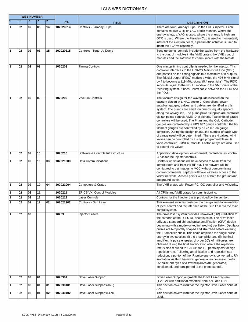
TITLE DESCRIPTION1 02 02 06 14 102020614 Controls - Faraday Cups There are four Faraday Cups in the LCLS injector. Each
contains its own OTR or YAG profile monitor. Where the energy is low, a YAG is used; where the energy is high, an OTR is used. Where the Faraday Cup is used to momentarily intercept the electron beam, a pneumatic actuator is used to insert the FC/PM assembly.
1 02 02 06 15 102020615 Controls - Tune-Up Dump Tune up dump controls include the cables from the hardware to the control modules in the VME crates, the VME control modules and the software to communicate with the toroids.
1 02 02 08 1020208 Timing Controls One master timing controller is needed for the injector. This controller interfaces to the LINAC’s Main Drive Line (MDL) and passes on the timing signals to a maximum of 8 outputs. The fiducial output (FIDO) module divides the 476 MHz signalby 4 to become a 119 MHz signal (8.4 nsec ticks). The FIDO sends its signal to the PDU II module in the VME crate of the receiving system. It uses Heliax cable between the FIDO and the PDU II.
1 02 02 09 1020209 Vacuum Controls The vacuum design for the waveguide is based on the vacuum design at LINAC sector 2. Controllers, power supplies, gauges, valves, and cables are identified in this system. The pumps are small ion pumps, equally spaced along the waveguide. The pump power supplies are controlledvia set points sent via VME IDIM signals. Two kinds of gauge controllers will be used. The Pirani and the Cold Cathode gauges are controlled by a HPS 937 gauge controller; the hot filament gauges are controlled by a GP307 Ion gauge controller. During the design phase, the number of each type of gauge used will be determined. There are 4 valves. All 4 valves can be controlled by a single programmable multi valve controller, PMVC6, module. Faston relays are also usedto control the valves.
1 02 02 10 1020210 Software & Controls Infrastructure Application development environment, control crates, control CPUs for the Injector controls.
1 02 02 10 03 102021003 Data Communications Controls workstations will have access to MCC from the control room and from the RF hut. The network will be configured to get images to MCC without compromising control commands. Laptops will have wireless access to the visitor network. Access points will be at both the ground and subground levels.
1 02 02 10 04 102021004 Computers & Crates The VME crates with Power PC IOC controller and VxWorks.
1 02 02 11 1020211 EPICS VXI Control Modules All CPUs and VME crates for commissioning.1 02 02 12 1020212 Laser Controls Controls for the Injector Laser provided by the vendor.1 02 02 12 02 102021202 Controls - Gun Laser This element includes costs for the design and documentation
of local control and the interface of the Gun Laser to the main control system.
1 02 03 10203 Injector Lasers The drive laser system provides ultraviolet (UV) irradiation to the cathode of the LCLS RF photoinjector. The drive laser utilizes a standard chirped pulse amplification (CPA) design beginning with a mode-locked infrared (ir) oscillator. Oscillatorpulses are temporally shaped and stretched before entering the IR amplifier chain. This chain amplifies the single pulse energy in two sections (i) the preamplifier and (ii) the final amplifier. Ir pulse energies of order 10’s of millijoules are obtained during the final amplification where the repetition rate is also reduced to 120 Hz, the RF photoinjector design repetition rate. Following amplification and repetition rate reduction, a portion of the IR pulse energy is converted to UV irradiation via third harmonic generation in nonlinear media. UV pulse energies of a few millijoules are generated, conditioned, and transported to the photocathode.
1 02 03 01 1020301 Drive Laser Support Drive Laser Support augments the Drive Laser System (1.2.3.2) with additional expertise from ANL and LLNL.
1 02 03 01 01 102030101 Drive Laser Support (ANL) This section covers work for the Injector Drive Laser done at ANL.
1 02 03 01 02 102030102 Drive Laser Support (LLNL) This section covers work for the Injector Drive Laser done at LLNL.
LCLS_WBS_Dictionary_LCLB_r4-031209.xls Page 5 of 63

LCLS WBS DICTIONARY
L1 L2 L3 L4 L5 CA
WBS NUMBER
TITLE DESCRIPTION1 02 03 02 1020302 Drive Laser System The drive laser system is the ultimate source of optical
irradiation for driving the LCLS RF photoinjector. The drive laser could be a chirped pulse amplification (CPA) scheme using TiS as the gain medium. A mode-locked master oscillator will operate at a 119 MHz repetition rate with a proposed central wavelength of 755 nm. Oscillator timing is referenced (and locked) to an external (SLAC) RF source. Oscillator establishes the maximum single pulse infrared (IR) bandwidth available to the drive laser system. Samples of the oscillator pulse energy can be used for diagnostics and diagnostic probe beams. The final high energy IR pulses will be produced via high gain broad band amplification of phase locked oscillator pulses through an amplifier chain.
1 02 03 02 1020302 Drive Laser System (Continued) The system includes the temporal IR pulse shaper which is intended to alter the temporal shape of the pulse exiting the oscillator from a nominally Gaussian temporal envelope to a nominally flattop (rectangular) envelope with specified steepness for rise and fall edges. Given the nominal rectangular envelope requirement, this device then establishes the duration (FWHM) and shape of the final high energy IR pulse to be used for UV conversion. Final IR pulses can be converted to UV pulses via third harmonic generation. The drive laser system including temporal pulse shaping and UV conversion will be built by an outside vendor. SLAC personnel will participate in the technical reviews and acceptance tests of all stages of the laser system.
1 02 03 03 1020303 Drive Laser Diagnostics The drive laser diagnostics includes several diagnostics clusters for each stage of the system: oscillator, preamplifier, final amplifier and UV conversion. Special ultra-fast high resolution diagnostics for the waveform (temporal shape) measurements will be designed by LLNL. The oscillator diagnostic cluster is intended to monitor the intrinsic oscillator output as well as the results of temporal pulse shaping and stretching. The diagnostic cluster includes a spatial profile imaging system, a fast photodiode, an average power sensor, a time-integrated spectrometer for monitoring bandwidth as well as mode-locked operation, and broadband time-resolved diagnostics for monitoring temporal pulse-width and shape (using techniques such as scanning autocorrelation and frequency-resolved optical-gating (FROG) detection). Where possible, diagnostics require only a sample of the oscillator pulse energy.
1 02 03 03 1020303 Drive Laser Diagnostics (Continued) The preamplifier diagnostic cluster is intended to monitor the preamplifier output. It includes fast photodiode detection, a pulse energy/power meter, spatial profile imaging, and broadband single pulse detection (as would be provided, for example, by polarization-gated frequency-resolved optical-gating detection (PG-FROG)). This single pulse broadband time-resolved detection monitors the temporal pulse shape (envelope) that is established between the preamplifier and the oscillator.
1 02 03 03 1020303 Drive Laser Diagnostics (Continued) Final amplifier diagnostics is used to monitor the final amplifier output prior to UV conversion. It includes fast diode detection, a time-integrating spectrometer, spatial profile imaging, energy/power sensors, and broadband time-resolvedsingle pulse diagnostics, with potential to add a single-pass oscillator probe beam. As with the preamplifier, single pulse broadband detection is used to monitor the established temporal pulse shape (envelope) with all amplifier effects included.
1 02 03 03 1020303 Drive Laser Diagnostics (Continued) The UV diagnostic cluster is located at the harmonic generation unit and monitors the UV pulse features prior to transport to the photocathode in the tunnel. It includes a fast photodiode, a pulse energy/power monitor, a time-integrated spectrometer, spatial profile imaging, and single pulse broadband time-resolved UV pulse detection (which will include a streak camera).
LCLS_WBS_Dictionary_LCLB_r4-031209.xls Page 6 of 63

LCLS WBS DICTIONARY
L1 L2 L3 L4 L5 CA
WBS NUMBER
TITLE DESCRIPTION1 02 03 04 1020304 Timing Stability Monitoring Timing stability is measured after the oscillator relative to an
external SLAC RF source.1 02 03 05 1020305 Steering Stability Feedback & Msmts Optical beam steering stability is measured after oscillator,
final amplifier and UV transport. UV steering stability measuring system is located in the tunnel next to the photocathode and its signal serves as the input to the feedback providing the active stabilization of the beam position.
1 02 03 07 1020307 Transport to Tunnel & Relay Optics Transport system refers to the system transmitting UV, visible and IR beams over the extended distance from the output of the Drive laser to the tunnel. UV beam is transmitted to the photocathode launch system, IR beam – to the Laser Heater and visible beam – to the EO diagnostics. Transport system incorporates the long vertical transport tubes with evacuation capabilities that extend from the laser bay to the tunnel. The relay optics is included in the system. Spatial filters will be used as needed. Spatial filter consists of a positive lens pair with a filtering on-axis pinhole placed between them. Due to the high pulse energy the space between lenses must be evacuated.
1 02 03 08 1020308 UV Launch, Conditioning & Diagnostics Important UV pulse conditioning issues (for photcathode irradiation) that finally bring the UV pulse parameters into compliance with the LCLS injector specifications are included here. These include final adjustments to temporal profile shaping at the IR oscillator level, spatial profile shaping and spatial filtering, the performance of UV launch optics near the gun photocathode, and electron beam-based UV pulse energy control. Spatial profile filtering and shaping are accomplished together by combining a UV ‘flattener’ with an input spot size selection using positive lenses. Grating-based launch optics set the required time slew and spatial anamorphic compression.
1 02 03 08 1020308 UV Launch, Conditioning & Diagnostics (Continued) The electron beam-based UV pulse energy control unit is a polarized optics assembly with a waveplate that can be tuned (via rotation) according to the electron bunch charge level. UV Launch and Conditioning system includes the components, which implement the beam steering and control of the beam size on the photocathode. The spatial profile and filtering as well as UV launch optics are set up along side the gun photocathode at the end of the UV transport section. The additional temporal shape control is implemented between theoscillator and preamplifier. The UV pulse energy control is located in the laser bay within the UV transport section and near the harmonic generation unit.
1 02 03 08 1020308 UV Launch, Conditioning & Diagnostics (Continued) The potential for final UV beam steering stabilization also exists here. Diagnostics refer to the cluster located at the gunsite near the photocathode in the tunnel. This cluster is to provide a final characterization of the UV pulse before irradiating the photocathode and incorporates the virtual cathode concept. It includes a fast photodiode, spatial profile imaging (incident and specular reflection from the photocathode), UV energy/power detection (incident and potentially specular reflection from the photocathode), and single pulse broadband time-resolved detection as needed.
1 02 03 11 1020311 LB Infrastructure & LB System Wide Items Drive laser system-wide components are included here. This includes, optical tables (in the laser bay and in the injector tunnel) and equipment for the Laser Bay and Optical Alignment Lab. Important laser-related reviews and preparation of the laser safety documents are also included here.
1 02 03 12 1020312 Alignment Laser The alignment laser is a visible CW diode source located along side the gun photocathode near the end of the UV transport section. Its purpose is to establish and to verify electron beam alignment down the evacuated electron beamline of the injector. This section includes the required steering and collimating optics (and required mounting hardware) that are located outside the vacuum beamline.
LCLS_WBS_Dictionary_LCLB_r4-031209.xls Page 7 of 63

LCLS WBS DICTIONARY
L1 L2 L3 L4 L5 CA
WBS NUMBER
TITLE DESCRIPTION1 02 03 13 1020313 Light path to Streak Camera This broad-band, visible optical path takes light from a prompt
Cherenkov view screen in the gun-to-linac region and images it onto the slit of a streak camera in the laser bay. Its purposeis to measure the electron beam bunch shape. The path optics should be imaging in order to measure transverse-longitudinal correlations between the bunch shape and time. The system includes lenses and mirrors and optical mounts, an alignment laser, mechanical supports and enclosures.
1 02 03 21 1020321 UV Conv Harmonic Generation Unit (Closed Account) Initial idea was for design and fabrication of UV conversion forlaser source. This task was then revised to implement as partof the laser (a purchased unit)
1 02 04 10204 Injector RF Subsystem System Summary for RF Gun, RF Distribution, RF structures and Low Level RF Systems.
1 02 04 01 1020401 RF Gun & Load Lock The RF Gun is at the north end of the Sector 20 alcove. This section covers all of the mechanical system associated with the operation of the gun and any cathode replacement scheme.
1 02 04 01 01 102040101 RF Gun This section specifically includes the copper brazed gun with a cathode, laser windows, and motorized tuners. It is similar to the GTF gun with an added second RF feed, see drawing SA-290-330-04-REV-1. This device will require cooling water (special), temperature sensors, tuner controls, vacuum, clean nitrogen gas, RF power, and laser light.
1 02 04 01 02 102040102 RF Gun Supports The RF Gun Support is at the north end of the Sector 20 Alcove. This section includes the small support between the gun and a larger table under the GTL area.
1 02 04 01 03 102040103 Gun Load Lock The Gun Load Lock is at the north end of sector 20 Alcove. Load Lock is a device which is attached to the RF Gun to replace gun cathode without venting electron beam line.
1 02 04 01 04 102040104 Gun Load Lock Supports The Gun Load Lock Support is at the north end of the Sector 20 Alcove. This section includes the small support between the load lock assembly and a larger table under the GTL area.
1 02 04 01 05 102040105 Gun Solenoid The Gun Solenoid is just downstream of the RF gun in the Sector 20 alcove. This section includes the solenoid magnet similar to the one in GTF, see drawing SA-290-330-64-REV-1, with a skew quad added to the inner bore. This device will require cooling water (LCW), temperature sensors, and electrical power.
1 02 04 01 06 102040106 Gun Solenoid Supports The Gun Solenoid Support is at the north end of the Sector 20Alcove. This section includes the small support between the solenoid and a larger table under the GTL area.
1 02 04 01 07 102040107 Gun RF Feed The Gun RF Feed is just above the RF gun in the Sector 20 alcove. This section includes a circulator, like a Titan TBC284D007 filled with SF6, two RF windows, and a RF splitter, similar to SA-700-870-66. This device will require SF6 and vacuum.
1 02 04 01 08 102040108 Gun RF Feed Supports The Gun RF Feed Support is at the north end of the Sector 20Alcove. This section includes the small support between the RF feed and a larger table under the GTL area.
1 02 04 01 09 102040109 RF Gun Spares Credit RF Gun Spares Credit from TEC to OPC1 02 04 02 1020402 Cathode Processing (CP) Station The cathode processing station is located in the control
building above the Injector Vault. This system is where final preparation of gun cathodes will occur prior to installation in replacement guns or the Load Lock System.
1 02 04 02 03 102040203 CP Load Lock Supports The GP Load Lock Support is in the load lock room of the of the Sector 20 LCLS facilities. This section includes the load lock support hardware and transportation cart. The GP load lock support should be compatibly with the RF gun load lock.
LCLS_WBS_Dictionary_LCLB_r4-031209.xls Page 8 of 63

LCLS WBS DICTIONARY
L1 L2 L3 L4 L5 CA
WBS NUMBER
TITLE DESCRIPTION1 02 04 03 1020403 S-Band Low Level Timing LLRF system consists of the RF components, less than 10kW
in peak power, required to maintain 70fS stability for the injector electronics. The scope of work includes the following:Modifications to the front end RF and timing system of the SLAC main linac, to achieve 70fS stability. A low phase noiseLCLS frequency source and distribution system located at the LCLS injector. RF phase and amplitude monitors including the heliax cables connected to the high power WR284 waveguide adapters. RF phase and amplitude control and drive amplifiers up to the 1kW input of the 5045 klystrons. Beam phase monitor system to include beamline device, all electronics and cables. User interface software and algorithmdevelopment for feedback loops.
1 02 04 03 01 102040301 Controls Interface & Timing The existing timing and RF distribution system for the two mile linac starts in sector 0 of the linac. The 476MHz Master Oscillator gets a timing pulse superimposed on it and drives the 2 mile Main Drive Line, MDL. Modifications to the RF system start with a lower phase noise master oscillator. The timing system will also be upgraded to meet the LCLS requirements. The output of this system will drive the 2 mile MDL with 30 watts at 476MHz.
1 02 04 03 02 102040302 LLRF Phase Reference System The phase reference system will include locking of a low noise oscillator to the linac RF reference. The 476 MHz reference will be multiplied to 2856MHz and distributed to the laser, RF gun, L0-1, L0-2, transverse accelerator, L1-X and L1-S drive and monitoring systems. Electronics for interfacing to the LASER phase lock. The electronics will be housed in a temperature controlled room enclosing penetration 20-17, which all the phase critical heliax cables will be run down.
1 02 04 03 03 102040303 LLRF Monitor & Control System Design and development of an RF phase and amplitude detector to measure the RF at the output of several high power waveguide couplers. Heliax cables are included here to connect to the high power waveguide couplers. Design and development of a solid state 1kW S-band amplifier to drive a 5045. Design and development of the RF control system used to adjust phase and amplitude of the high power RF components. Control cables to connect to modules in a control create are also included here.
1 02 04 03 04 102040304 Beam Phase Monitor Cavity Development of a beam phase monitoring system. The desired sensitivity of this system is about 50fS on a single pulse. Includes the beam line component, RF detectors, and interfaces to the control system. All electronics and cables upto the control create modules are included here.
1 02 04 05 1020405 Injector RF Waveguide Subsystem The INJECTOR RF WAVEGUIDE is located and extends through three different areas: the sector 20 injector alcove, the main LINAC housing, and the klystron gallery. It is split into four systems each fed from a separate klystron. The systems feed the GUN, each of two injector accelerator sections and one transverse kicker section. Three of the systems travel down the ceiling of the klystron gallery, down through a LINAC housing penetration into the main LINAC housing and through the shield wall into the sector 20 injector alcove. The fourth system travels down the LINAC housing and through the shield wall into the sector 20 injector alcove. The systems require vacuum pumping, temperature controlled water and controls feedback. The RF waveguide transports microwave energy from the klystrons to injector beam line components
1 02 04 05 01 102040501 RF Waveguides RF Waveguide includes the costs to design, fabricate, and test discrete sections of UHV High Power S-Band copper Waveguide for the Injector. This section also includes all integral support strong backs, and vacuum hardware in support of the installed system.
1 02 04 05 02 102040502 RF Waveguide Supports RF waveguide supports includes the costs to design, and fabricate. This section also includes all integral support strong backs, and vacuum hardware in support of the installed system
1 02 04 06 1020406 Injector Linac Structures System Summary for accelerating structures in the Injector scope.
LCLS_WBS_Dictionary_LCLB_r4-031209.xls Page 9 of 63

LCLS WBS DICTIONARY
L1 L2 L3 L4 L5 CA
WBS NUMBER
TITLE DESCRIPTION1 02 04 06 01 102040601 L0A-0B Structure Assembly The LO-1 LINAC section is mounted on the major tube
support directly after the gun spectrometer in the sector 20 alcove. This is the first booster section after the gun and is surrounded by a solenoid magnet. This device will require controlled temperature water, temperature sensors, electronics and RF waveguide power from a klystron. It also has a load attached to it and RF couplers for feedback. There is a set of flexures and a strong back support attached to the section. This is the first stage for boosting the beam energy in the injector area. Design and fabrication for both L0A and L0B.
1 02 04 06 03 102040603 Major Linac Support Support structure for both L0A and L0B. The L0A support must also provide support for the L0A solenoid on a common strongback.
1 02 04 06 05 102040605 LTDL1 RF Kicker The LTDL1 RF KICKER is located just after the LASER heater and before the first shield wall in the Sector 20 alcove. This device will require supports, a RF waveguide feed and feedback coupler along with the necessary electronics. It will momentarily deflect the beam proportionally along its' length to measure the longitudinal phase space parameters.
1 02 05 10205 Injector Magnets & Supports This section collects all of the Injector magnets and their associated local supports and alignment hardware.
1 02 05 01 1020501 Injector Dipoles All bending magnets necessary for the Injector System.1 02 05 01 01 102050101 Gun Spectrometer Dipole The GS Dipole is just downstream of the RF gun in the Sector
20 alcove. This section includes a dipole magnet and its support. This device will require cooling water (LCW), temperature sensors, and electrical power. It will be used to bend the beam about 90 degrees to measure the beam energy. It needs to have zero residual field when turned off - this may require special trim coils.
1 02 05 01 02 102050102 DL1 B01 & B02 Dipoles The DL1 B01 & B02 DIPOLES are located in the LINAC housing at the point where the injector beam turns to match the main LINAC beam line. This section includes the two dipole magnets and location adjustment supports. These magnets will require cooling water (LCW), temperature sensors, and electrical power supplies. They will bend the beam 35 degrees to match the main LINAC beam trajectory. The magnets require zero residual field when switched off - this will be accomplished using the trim coils.
1 02 05 01 03 102050103 SAB Spectrometer Dipole The SAB Dipole is located at the end of the straight section of the injector in the main LINAC housing. This section includes a dipole magnet and its support. This device will require cooling water (LCW), temperature sensors, and an electrical power supply. It will be used to bend the beam about 35 degrees to measure the beam energy. It acts as a beam diagnostic device.
1 02 05 01 04 102050104 Chicane DIPOLES (4) The chicane magnets are part of the laser heater system. They comprise a four-magnet bump that displaces the electron beam by 25 mm through an undulator. The displacement is to allow an infrared laser beam to be co-propagated with the electron beam in the undulator, in order to increase the uncorrelated energy spread of the electron beam. This has the effect of smoothing micro-instabilities in the beam to reduce enhancement of these instabilities in the bunch compressors. The downstream pair of magnets in the chicane help to transform the energy gained from the laser interaction into geometrical smoothing.
1 02 05 02 1020502 Injector Quads All focusing and defocusing magnets necessary for the Injector System.
1 02 05 02 01 102050201 Gun Spectrometer Quadrupoles The GS quad magnets are just downstream of the RF gun in the Sector 20 alcove. Two are just before the spectrometer dipole and one is just to the side of the spectrometer dipole. This section includes 3 quad magnets and their supports. These devices will require cooling water (LCW), temperature sensors, and electrical power.
LCLS_WBS_Dictionary_LCLB_r4-031209.xls Page 10 of 63

LCLS WBS DICTIONARY
L1 L2 L3 L4 L5 CA
WBS NUMBER
TITLE DESCRIPTION1 02 05 02 02 102050202 Injector Quadrupoles This is a single model of Injector System Quadrupole that is
used in multiple locations throughout the Injector System.
1 02 05 02 03 102050203 LTDL1 Quadrupoles (4) This is a single model of Injector System Quadrupole that is used in multiple locations throughout the Injector System.
1 02 05 03 1020503 Injector Steering Coils All Steering Coils necessary for the Injector System.1 02 05 03 01 102050301 Gun Solenoid Correctors These are sets of steering correction coils that are integral
with the Gun solenoid.1 02 05 03 03 102050303 Injector Correctors - A These are sets of general use steering correction coils for use
in the Injector System1 02 05 03 05 102050305 Gun Solenoid Quadrupole Correctors These are sets of general use steering correction coils
integral with the SAB Spectrometer Quadrupole.1 02 05 04 1020504 Linac Solenoid The LINAC Solenoid is mounted over the input end of LO-1.
This solenoid magnet is similar in function to the one located in the CID area of the main linac. This device will require cooling water (LCW), temperature sensors, and electrical power. The solenoid acts to focus and collect the beam.
1 02 05 05 1020505 Injector Laser Heater Subsystem This is a system designed to add uncorrelated energy to the LCLS beam in the injector, at 150 MeV, by crossing an IR laser beam with the electron beam in an undulator. The system starts just past a dichroic beam splitter that is downstream from the drive laser doubling crystals. The IR beam that is not absorbed by the doubling crystals passes through an optics system on the drive laser table, down to the linac tunnel, into the electron beamline, along the electron beam in a chicane, and out into a diagnostic system at the end.
1 02 05 05 02 102050502 Injector Undulator A variable gap hybrid undulator 1 meter or shorter in length, with 50 mm period and 28 mm gap that is intended to give theinjector beam transverse motion to allow it to couple to a co-propagating IR laser beam. Establishment of the physical, mechanical, magnetic, and beam dynamic parameters of the undulator, and generation of a technical description suitable for presentation to vendors for RFQ. A design review of the undulator that will consider its physics, mechanical and magnet engineering, and the modeling from which the variousparameters were developed. This review should include some participation from outside SLAC. An assembly level drawing of the undulator; more refined designs will come fromthe vendor if the undulator is built outside, or from further SLAC designs if we build it here.
1 02 05 05 02 102050502 Injector Undulator (Continued) Choice of internal or external construction. If internal construction is chosen, selection of personnel to do the work, and supervision of the work. If external construction is chosen, sending of bid packages, choice of vendor, possible vendor design review, supervision of contract, expediting and checking of item on receipt. If the undulator is awkward or difficult to install, rigging must be designed to put it into place. This requirement is much reduced as of placement of the undulator upstream from the shielding walls. Fabrication of any rigging required for emplacement of undulator. Measurements by the SLAC magnetic measurements group of the magnetic fields of the undulator, to verify that the device meets its specifications. This work will also include calibration of trim coils provided to cancel the earth's field and any residual dipole errors.
1 02 06 10206 Injector Vacuum & Supports Summary of all vacuum system component and support costs as outlined by the general ICD.
1 02 06 01 1020601 Injector Vacuum Engineering All engineering associated with the design, fabrication, planning and oversight for the Injector Vacuum System
1 02 06 02 1020602 Injector Vacuum Components Covers the cost of general components. (gages, pumps, valves, feedthroughs, and other commercial vacuum components)
1 02 06 03 1020603 Injector Vacuum Special Chambers This section covers the cost of design and fabrication of special chambers not associated and covered by a specific component and or diagnostic.
LCLS_WBS_Dictionary_LCLB_r4-031209.xls Page 11 of 63
LCLS WBS DICTIONARY
L1 L2 L3 L4 L5 CA
WBS NUMBER
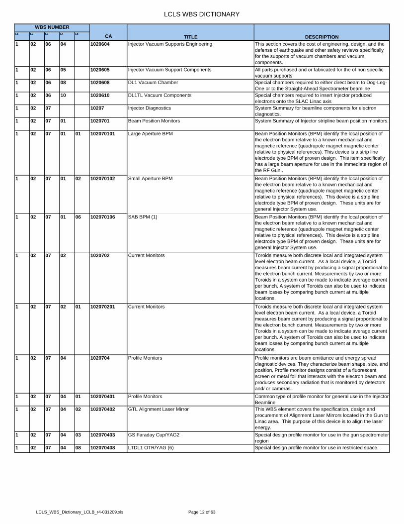
TITLE DESCRIPTION1 02 06 04 1020604 Injector Vacuum Supports Engineering This section covers the cost of engineering, design, and the
defense of earthquake and other safety reviews specifically for the supports of vacuum chambers and vacuum components.
1 02 06 05 1020605 Injector Vacuum Support Components All parts purchased and or fabricated for the of non specific vacuum supports
1 02 06 08 1020608 DL1 Vacuum Chamber Special chambers required to either direct beam to Dog-Leg-One or to the Straight-Ahead Spectrometer beamline
1 02 06 10 1020610 DL1TL Vacuum Components Special chambers required to insert Injector produced electrons onto the SLAC Linac axis
1 02 07 10207 Injector Diagnostics System Summary for beamline components for electron diagnostics.
1 02 07 01 1020701 Beam Position Monitors System Summary of Injector stripline beam position monitors.
1 02 07 01 01 102070101 Large Aperture BPM Beam Position Monitors (BPM) identify the local position of the electron beam relative to a known mechanical and magnetic reference (quadrupole magnet magnetic center relative to physical references). This device is a strip line electrode type BPM of proven design. This item specifically has a large beam aperture for use in the immediate region of the RF Gun..
1 02 07 01 02 102070102 Small Aperture BPM Beam Position Monitors (BPM) identify the local position of the electron beam relative to a known mechanical and magnetic reference (quadrupole magnet magnetic center relative to physical references). This device is a strip line electrode type BPM of proven design. These units are for general Injector System use.
1 02 07 01 06 102070106 SAB BPM (1) Beam Position Monitors (BPM) identify the local position of the electron beam relative to a known mechanical and magnetic reference (quadrupole magnet magnetic center relative to physical references). This device is a strip line electrode type BPM of proven design. These units are for general Injector System use.
1 02 07 02 1020702 Current Monitors Toroids measure both discrete local and integrated system level electron beam current. As a local device, a Toroid measures beam current by producing a signal proportional to the electron bunch current. Measurements by two or more Toroids in a system can be made to indicate average current per bunch. A system of Toroids can also be used to indicate beam losses by comparing bunch current at multiple locations.
1 02 07 02 01 102070201 Current Monitors Toroids measure both discrete local and integrated system level electron beam current. As a local device, a Toroid measures beam current by producing a signal proportional to the electron bunch current. Measurements by two or more Toroids in a system can be made to indicate average current per bunch. A system of Toroids can also be used to indicate beam losses by comparing bunch current at multiple locations.
1 02 07 04 1020704 Profile Monitors Profile monitors are beam emittance and energy spread diagnostic devices. They characterize beam shape, size, and position. Profile monitor designs consist of a fluorescent screen or metal foil that interacts with the electron beam and produces secondary radiation that is monitored by detectors and/ or cameras.
1 02 07 04 01 102070401 Profile Monitors Common type of profile monitor for general use in the Injector Beamline
1 02 07 04 02 102070402 GTL Alignment Laser Mirror This WBS element covers the specification, design and procurement of Alignment Laser Mirrors located in the Gun to Linac area. This purpose of this device is to align the laser energy.
1 02 07 04 03 102070403 GS Faraday Cup/YAG2 Special design profile monitor for use in the gun spectrometer region
1 02 07 04 08 102070408 LTDL1 OTR/YAG (6) Special design profile monitor for use in restricted space.
LCLS_WBS_Dictionary_LCLB_r4-031209.xls Page 12 of 63

LCLS WBS DICTIONARY
L1 L2 L3 L4 L5 CA
WBS NUMBER
TITLE DESCRIPTION1 02 07 05 1020705 Injector Wire Scanners Wire scanners utilize a set of wires that move with the respect
of the beam centroid pulse to pulse. The radiation produced isproportional to the density of the portion of the pulse intercepted. A correlation of radiation to wire-position can reconstruct the average beam profile. A combination of three or more wire scanners with adequate betatron offset can be used to measure beam emmittance. THese wire scanners measure beam emmittance at the 135MeV point prior to insertion into the SLAC Linac.
1 02 07 07 1020707 PPS Stopper The LTDL1 PPS Stopper is located between the two shield walls. The stopper protects people in the sector 20 Injector vault during normal LINAC operation when they service injector components in the gun and booster linac in the vault. This device will require air and actuation control electronics.
1 02 17 10217 Injector Installation & Alignment System Summary for installation of beamline components, controls hardware and cabling.
1 02 17 01 1021701 Injector Infrastructure Installation This section accounts for the general installation activities for the Injector tunnel at Sector 20. The activities are wide ranging and vary from, to alignment network and device footprints, to the installation completion of cable tray and other utilities. Post delivery operations like component alignment, pump down and leak check as well as all other operations that are necessary to bring the injector to ‘commissioning’ are included in this section for injector infrastructure.
1 02 17 02 1021702 Injector Controls Subsystem Install & Align This section accounts for the specific tasks associated with the field installation of the specific Injector section.
1 02 17 03 1021703 Injector Lasers Install & Align This section accounts for the specific tasks associated with the field installation of the specific Injector section. Specifically included; Laser Bay in the Control Room, Laser Transport to Injector Vault (penetration), and Laser Paths in the Injector Vault to the Heater and eventually into the Linac Housing.
1 02 17 04 1021704 Gun Area Integration This section accounts for the specific tasks associated with the field installation of the specific Injector section.
1 02 17 06 1021706 Accelerator Area Integration This section accounts for the specific tasks associated with the field installation of the specific Injector section.
1 02 17 07 1021707 Heater Area Integration This section accounts for the specific tasks associated with the field installation of the specific Injector section.
1 02 17 08 1021708 Wall Area Integration This section accounts for the specific tasks associated with the field installation of the specific Injector section.
1 02 17 09 1021709 Insertion Area Integration This section accounts for the specific tasks associated with the field installation of the specific Injector section.
1 02 17 12 1021712 Injector RF High Power System Install & Align This section accounts for the specific tasks associated with the field installation of the specific Injector section.
1 03 103 LINAC SYSTEM The Linac accelerates the electron beam while preserving the transverse emittance and compressing the longitudinal size. This element includes modifications to the last third of the existing SLAC linac, Bunch Compressor 1 (BC1), Bunch Compressor 2 (BC2), beam transport to the Undulator (LTU), beam transport after the undulator, bend magnets and beam dump, the bypass system for transporting test beams to end station A, and diagnostics including characterizing both the electron and x-ray beams as they pass through the undulator. The interface with the undulator is a vacuum flange at each end of the undulator. This element includes the common beam line beyond the undulator for the electrons and x-rays until the electrons are deflected enough for an interface to the x-ray beam line.
1 03 01 10301 System Management & Integration The Linac is made up of a number of individual devices and systems. These devices and systems must be integrated into functional blocks. In consecutive order with respect to the electron beam the functional blocks or areas are: Linac 1 (L01), Bunch Compressor Chicane 1 (BC1), Linac 2 (L02), Bunch Compressor Chicane 2 (BC2), Linac 3 (L03), Linac-to-Undulator Transport Line (LTU), and Main Electron Dump (E-Dump).
LCLS_WBS_Dictionary_LCLB_r4-031209.xls Page 13 of 63

LCLS WBS DICTIONARY
L1 L2 L3 L4 L5 CA
WBS NUMBER
TITLE DESCRIPTION1 03 01 01 1030101 Linac Mechanical Integration Linac Mechanical Integration defines a physical envelope for
the LCLS modifications in the Accelerator Housing and Klystron Gallery. Mechanical Integration also ensures that existing Linac systems are, once modified by LCLS, returned to an acceptable level of function along with complete documentation.
1 03 01 01 01 103010101 L01 System Integration L01 accelerates and ‘chirps’ the electron beam in preparation for first stage BC1 compression. Representing an LCLS Linacfunctional block, it is here where the functional requirements for systems and components are presented, reviewed, and documented. The mechanical top assembly of this functional area is completed here.
1 03 01 01 02 103010102 BC1 System Integration BC1 applies first stage bunch compression to the electron beam. Representing an LCLS Linac functional block, it is herewhere the functional requirements for systems and components are presented, reviewed, and documented. The mechanical top assembly of this functional area is completed here.
1 03 01 01 03 103010103 L02 System Integration L02 accelerates and ‘chirps’ the electron beam in preparation for first stage BC1 compression. Representing an LCLS Linacfunctional block, it is here where the functional requirements for systems and components are presented, reviewed, and documented. The mechanical top assembly of this functional area is completed here.
1 03 01 01 04 103010104 BC2 System Integration BC2 applies second stage bunch compression to the electron beam. Representing an LCLS Linac functional block, it is herewhere the functional requirements for systems and components are presented, reviewed, and documented. The mechanical top assembly of this functional area is completed here.
1 03 01 01 05 103010105 L03 System Integration L3 accelerates the electron beam to a final energy of 14 Gev. Representing an LCLS Linac functional block, it is here wherethe functional requirements for systems and components are presented, reviewed, and documented. The mechanical top assembly of this functional area is completed here.
1 03 01 01 06 103010106 LTU System Integration LTU transports the electron beam to the FEL Undulator. The system includes bend magnets that support energy and emittance diagnostics. Representing an LCLS Linac functional block, it is here where the functional requirements for systems and components are presented, reviewed, and documented. The mechanical top assembly of this functional area is completed here
1 03 01 01 07 103010107 E-Dump System Integration The Electron Dump receives the electron beam from the FEL Undulator and terminates the electron stream. It is a high radiation area with possibly some beam diagnostic capabilities. Representing an LCLS Linac functional block, it is here where the functional requirements for systems and components are presented, reviewed, and documented. The mechanical top assembly of this functional area is completed here
1 03 01 03 1030103 Travel Linac group project-related travel expenditures.1 03 01 04 1030104 Linac Management Linac group costs related to management; administration,
personal computers, productivity software, as well as simulation and modeling software.
1 03 02 10302 Linac Controls & Power Conversion Subsystem Provide an EPICS based control system for the portions of the linac that are modified for LCLS use.
1 03 02 01 1030201 Personnel Protection System (PPS) This system creates a physical barrier that subtends the LCLS for the purpose of personnel protection from radiation, electrical, and other present or imagined hazards. An LCLS area may use or combine with other SLAC control areas. The PPS system will include monitoring of radiation shielding integrity, barriers, area status annunciators, and multiple interlocked control gates for access to a safe machine space.
LCLS_WBS_Dictionary_LCLB_r4-031209.xls Page 14 of 63
LCLS WBS DICTIONARY
L1 L2 L3 L4 L5 CA
WBS NUMBER
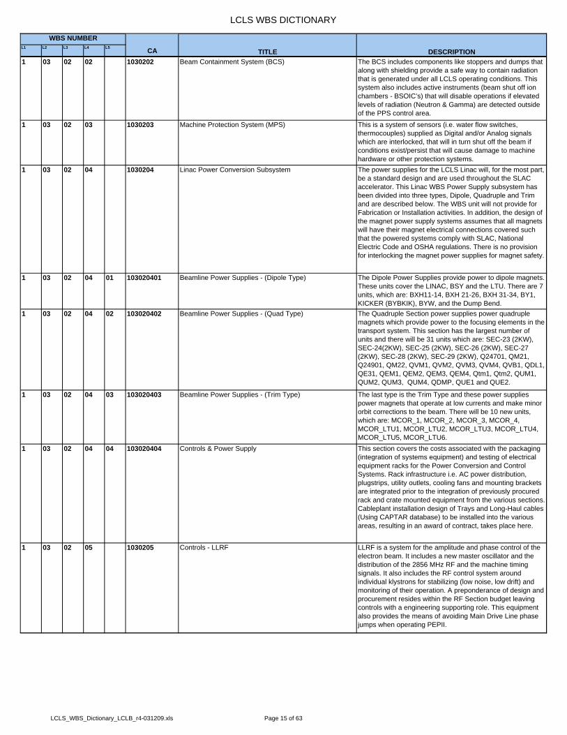
TITLE DESCRIPTION1 03 02 02 1030202 Beam Containment System (BCS) The BCS includes components like stoppers and dumps that
along with shielding provide a safe way to contain radiation that is generated under all LCLS operating conditions. This system also includes active instruments (beam shut off ion chambers - BSOIC’s) that will disable operations if elevated levels of radiation (Neutron & Gamma) are detected outside of the PPS control area.
1 03 02 03 1030203 Machine Protection System (MPS) This is a system of sensors (i.e. water flow switches, thermocouples) supplied as Digital and/or Analog signals which are interlocked, that will in turn shut off the beam if conditions exist/persist that will cause damage to machine hardware or other protection systems.
1 03 02 04 1030204 Linac Power Conversion Subsystem The power supplies for the LCLS Linac will, for the most part, be a standard design and are used throughout the SLAC accelerator. This Linac WBS Power Supply subsystem has been divided into three types, Dipole, Quadruple and Trim and are described below. The WBS unit will not provide for Fabrication or Installation activities. In addition, the design of the magnet power supply systems assumes that all magnets will have their magnet electrical connections covered such that the powered systems comply with SLAC, National Electric Code and OSHA regulations. There is no provision for interlocking the magnet power supplies for magnet safety.
1 03 02 04 01 103020401 Beamline Power Supplies - (Dipole Type) The Dipole Power Supplies provide power to dipole magnets. These units cover the LINAC, BSY and the LTU. There are 7 units, which are: BXH11-14, BXH 21-26, BXH 31-34, BY1, KICKER (BYBKIK), BYW, and the Dump Bend.
1 03 02 04 02 103020402 Beamline Power Supplies - (Quad Type) The Quadruple Section power supplies power quadruple magnets which provide power to the focusing elements in the transport system. This section has the largest number of units and there will be 31 units which are: SEC-23 (2KW), SEC-24(2KW), SEC-25 (2KW), SEC-26 (2KW), SEC-27 (2KW), SEC-28 (2KW), SEC-29 (2KW), Q24701, QM21, Q24901, QM22, QVM1, QVM2, QVM3, QVM4, QVB1, QDL1, QE31, QEM1, QEM2, QEM3, QEM4, Qtm1, Qtm2, QUM1, QUM2, QUM3, QUM4, QDMP, QUE1 and QUE2.
1 03 02 04 03 103020403 Beamline Power Supplies - (Trim Type) The last type is the Trim Type and these power supplies power magnets that operate at low currents and make minor orbit corrections to the beam. There will be 10 new units, which are: MCOR_1, MCOR_2, MCOR_3, MCOR_4, MCOR_LTU1, MCOR_LTU2, MCOR_LTU3, MCOR_LTU4, MCOR_LTU5, MCOR_LTU6.
1 03 02 04 04 103020404 Controls & Power Supply This section covers the costs associated with the packaging (integration of systems equipment) and testing of electrical equipment racks for the Power Conversion and Control Systems. Rack infrastructure i.e. AC power distribution, plugstrips, utility outlets, cooling fans and mounting brackets are integrated prior to the integration of previously procured rack and crate mounted equipment from the various sections. Cableplant installation design of Trays and Long-Haul cables (Using CAPTAR database) to be installed into the various areas, resulting in an award of contract, takes place here.
1 03 02 05 1030205 Controls - LLRF LLRF is a system for the amplitude and phase control of the electron beam. It includes a new master oscillator and the distribution of the 2856 MHz RF and the machine timing signals. It also includes the RF control system around individual klystrons for stabilizing (low noise, low drift) and monitoring of their operation. A preponderance of design and procurement resides within the RF Section budget leaving controls with a engineering supporting role. This equipment also provides the means of avoiding Main Drive Line phase jumps when operating PEPII.
LCLS_WBS_Dictionary_LCLB_r4-031209.xls Page 15 of 63

LCLS WBS DICTIONARY
L1 L2 L3 L4 L5 CA
WBS NUMBER
TITLE DESCRIPTION1 03 02 06 1030206 Controls - E-Beam Diagnostic Diagnostic devices measure salient beam parameters such
as beam size, position, phase, bunch length, beam current etc. for the purposes of setting and tuning the various machine parameters such as the strength of magnets and the amplitude and phase of klystrons. The diagnostic signals provide a monitoring function and in some case a direct feedback for closed-loop control of the accelerator hardware.
1 03 02 06 01 103020601 Controls - Wire Scanners Wire scanners are beam profile monitors used to provide accurate measurements of beam size and position in all three planes (vertical, horizontal and 45 degrees) for beam measurement systems and beam tuning procedures. Components include wires capable of being moved precisely through the path of a beam, and a detector which can accurately measure the amount of charge striking a wire. When in use, a wire is scanned across the path of a beam using stepper motors, and a plot of wire position versus beam intensity is generated that represents the beam profile.
1 03 02 06 02 103020602 Controls - BPMs Beam Position Monitor. A device including four electrodes located inside the beam pipe, and the associated electronics necessary to locate the position of the centroid of the beam. The electrodes are usually located about 90 degrees apart inside the vacuum chamber, far enough away from the beam's path not to interfere with it, but close enough to feel the electric charge of the beam's passing. A device called an RF cavity BPM uses resonant cavities in place of electrodes to detect the electric charge of the beam.
1 03 02 06 03 103020603 Controls - Toroids The Toroid is an average beam current (charge) monitor (CM) which uses transformer action to measure the intensity of a beam pulse. A lead shielded pre-amplifier is usually placed near and connected to the wire wound ferrites. The amplified signal is then cabled to an electronic module external to the shielded housing. Comparisons can be made between Toroid installations as a way of determining beam losses between two points.
1 03 02 06 04 103020604 Controls - Stoppers A Personnel Protection System device used to stop the beam,usually by allowing a heavy metal slug to pivot into the beam'spath. The de-energized default is in the beam path as a fail-safe. This is removed from the path by means of air solenoids. This device, as all PPS devices rely on redundant parallel limit switches to supply status prior to allowing entry into beamline areas.
1 03 02 06 05 103020605 Controls - Profile Monitors A screen inserted is inserted into a beam transport line to view the beam cross section via a remote camera focused through a glass viewing port. The screen can be made from a variety of materials suited to the beam energy at that location. The visible emission picture is captured on a digital video camera, triggered to look a specific beam pulse. Profile monitor screens can be inserted and removed remotely by themachine operators. Position status is determined by limit switches. Cameras can be remotely triggered, iris controlled, zoom activated, lamp intensity varied via electronic modules connected to a two channel Profile Monitor chassis.
1 03 02 06 07 103020607 Controls - Bunch Length Monitors The bunch length monitor, BLM, is used to measure the length of the bunch after each longitudinal compression stage in the accelerator. The measurement is done on a pulse-by-pulse basis so that the information can be transmitted to a feedback loop for control and stabilization of the bunch length. The BLM device senses the coherent radiation from the bunch, where the spectral power is proportional to the peak current in the bunch and so is able to detect relative changes in bunch length. For calibration purposes this measurement is compared to measurements made with the RF transverse deflecting cavities.
LCLS_WBS_Dictionary_LCLB_r4-031209.xls Page 16 of 63

LCLS WBS DICTIONARY
L1 L2 L3 L4 L5 CA
WBS NUMBER
TITLE DESCRIPTION1 03 02 06 09 103020609 Controls - Single Beam Dump The single bunch beam dumper, SBBD, consists of a fast-
acting pulsed magnet that is able to selectively deflect a bunch toward a beam stopper on a pulse-by-pulse basis. The purpose of this is to control the rate at which beam is sent to the downstream undulator beam line which contains sensitive equipment. If a fault condition occurs such as a beam loss in the undulator then the SBBD is able to prevent the next beam pulse from being sent down the beam line and potentially causing damage. The fault conditions are passed to the SBBD from the Machine Protection System, MPS. The SBBDis able to stop the full-rate 120 Hz beam from the linac upstream and selectively allow single shots, 1 Hz, 10 Hz or anarbitrary rate to be sent downstream, thereby facilitating tune up of the beam without risking damage to the beam line.
1 03 02 06 10 103020610 Controls - E Beam Dump The main electron beam dump is used to safely stop the spent electrons after the undulator. The design of the dump addresses issues of cooling the maximum possible heat load from the electron beam with regard to thermal stress and corrosion problems to ensure that the radiation in the dump is fully contained. The control system monitors temperatures and coolant systems for long-term reliability.
1 03 02 06 11 103020611 Controls - Protection Collimator These fixed mask devices are a principal initial means of scraping errant beams thereby preventing damage to beamline components and/or beampipe if not outright venting of the vacuum envelope. Water flow and temperatures are monitored using distributed digital and analog input modular devices via signal interfaces.
1 03 02 06 12 103020612 Controls - Movable Collimator This system provides control and monitoring of two-axis beamintercepting blades which can be used as a diagnostic in the LTU front end and further downstream for beam clean-up. Stepper-motors are used for movement which is read back with transducers (LVDT’s) for positional information.
1 03 02 06 13 103020613 Controls - X-Band Accel Structure Provide the hardware and software for the LLRF control of theX-band accelerating structure
1 03 02 08 1030208 Controls - Timing This system includes the synchronization of pulsed accelerator devices with generating the beam and the acquisition of beam measurements for use in feedback and timing.
1 03 02 09 1030209 Controls - Vacuum This system includes the monitoring and control of gages, pumps, and valves. This system includes interlocks for the protection of the machine during maintenance and against a catastrophic change in pressure.
1 03 02 09 01 103020901 Controls - Vacuum Instrumentation & Interlocks This system collects and displays the operating state of vacuum system in discrete areas of the accelerator. It uses this information to control beam operation as well as the state of isolation valves and vacuum pump power supplies.
1 03 02 09 02 103020902 Vacuum Instrumentation & Controls These are High Voltage power supplies, controlled current, to pump down and maintain design operating pressure in the accelerator.
1 03 02 10 1030210 Software & Controls Infrastructure The controls infrastructure provides the interconnection between various parts of the control system. It performs supervisory function for the control network. It includes the software tools and applications for the real time programming of the control modules as well as the tools for supporting the database structure.
1 03 02 10 04 103021004 Data Communications Gigabit networking has been costed to connect 5 locations to MCC. The locations are: Bldg 406, sector 24, sector 30, support bldg at near end and the end of the LTU. One gigabit switch has been allocated per location except at the end station, where two have been allocated because of the high quantity of cameras at this location. Wireless network access points (to the visitor network) are also included.
1 03 02 10 05 103021005 Computers This is actually "Computers and crates". VME crates with Power PC controllers and VxWorks run-time licenses have been costed for all systems. The cables and the modules that go in the crates are distributed across the systems (in the rest of the controls WBS) that use/need them. No workstations have been costed for the Linac controls.
LCLS_WBS_Dictionary_LCLB_r4-031209.xls Page 17 of 63

LCLS WBS DICTIONARY
L1 L2 L3 L4 L5 CA
WBS NUMBER
TITLE DESCRIPTION1 03 03 10303 Linac Magnets & Supports This system may include permanent and electromagnetic
elements (dipoles, quadrupoles, sextupoles, and correctors) for the manipulation and direction of charged beams. The structure and systems to locate and accurately position these elements are included in the system.
1 03 03 01 1030301 Bend Magnet (BX1_BC1) This is a new bend magnet design for use in BC1. It is direct current string of four magnets powered to bend the electron beam into and out of the BC1 chicane. The final alignment stage for each magnet and support stand for the entire BC1 system have been cost with these components.
1 03 03 02 1030302 Bend Magnet (BX3_LTU) This is an existing bend magnet design for use in the LTU. Five existing bend magnets will be recycled from SLAC / FFTB. One of the five will become the first bend in the dump line in front of the BYD bend magnets.
1 03 03 03 1030303 Bend Magnet (BX2_BC2) This is a new bend magnet design for use in BC1. It is direct current string of four magnets powered to bend the electron beam into and out of the BC2 chicane. The final alignment stage for each magnet and support stand for the entire BC2 system have been cost with these components.
1 03 03 04 1030304 Bend Magnet (BY_LTU) This is a new bend magnet design for use in the LTU. It is a direct current powered to bend the electron beam in a vertical plane in the LTU.
1 03 03 05 1030305 Quad Magnet (Quad_LTU) These magnets are an existing design. Fifteen additional unitswill have to be fabricated to augment the lot of existing refurbished units that will be removed from FFTB.
1 03 03 07 1030307 Quad Magnet (QE) This is an existing linac design(s) of a laminated steel quadrupole. It is used to focus or defocus the electron beam. They are usually found at linac intergirder and or drift locations. The majority of these magnetic elements already exists in the current linac and will assume new position and control for LCLS.
1 03 03 08 1030308 Corrector Magnet (Type 4) This is an existing linac design for a weak (iron core) bend magnet. Its large appeture allows for installation over the accelerating structure. They provide bend correction for the electron beam. A single design can be installed in either a vertical or horizontal orientation. The majority of these magnetic elements exists in the current linac and will assume new position and control for LCLS.
1 03 03 09 1030309 Bend Magnet (BYD_DUMP) This is a new direct current electromagnetic dipole that bends the bends the spent electron beam after the Undulator and directs it to the main dump. Along with other magnetic elements, this magnet is part of a spectrometer that analyzes the energy distribution of the discarded electrons that reach the dump.
1 03 03 10 1030310 Quad Magnet (QA) This is an existing linac Quadrupole magnet for focusing or defocusing of the electron beam. They are usually found at linac intergirder and or drift locations. The majority of these magnetic elements already exists in the current linac and will assume new position and control for LCLS.
1 03 03 11 1030311 Bend Magnet (BYPM_LTU) This is a new system of permanent dipole magnets located immediately after the dump bend magnet that directs the electron beam into a safe shielding zone in the event of a failure of the Dump Bend Magnet.
1 03 03 12 1030312 Bend Magnet (BYKIK_LTU) This is a new pulsed magnet in the LTU that limits the rate of beam bunches into the Undulator by deflecting unwanted bunches out of the forward Beamline into the Single Beam Dump.
1 03 03 13 1030313 Bend Magnet (BYW_LTU) This magnet system is a diagnostic device rather than a beamtransport element. The magnet for this application will be a refurbished item from SSRL.
1 03 03 14 1030314 BXKIK LINAC TCAV Screen Kicker This WBS section identifies and collects the resources and costs associated with the BXKIK LINAC TCAV Screen Kicker.
1 03 04 10304 Linac Vacuum Subsystem Section Summary
LCLS_WBS_Dictionary_LCLB_r4-031209.xls Page 18 of 63

LCLS WBS DICTIONARY
L1 L2 L3 L4 L5 CA
WBS NUMBER
TITLE DESCRIPTION1 03 04 02 1030402 Linac Beamline Vacuum System This section represents all of the interconnecting vacuum
parts between accelerating, magnetic, or diagnostic components for the identified LCLS system. It includes, but is not limited too, drifts, tees, pumps, gauges, pumps, and manifolds. Gauge controllers and ion pump controllers are notincluded in this section. They are estimated under WBS 1.3.2.9. Cutting and re-assembly of accelerator structures are not covered under this WBS number. Those activities are covered under WBS 1.3.6.2.
1 03 04 03 1030403 BC1 Vacuum System This section represents all of the interconnecting vacuum parts between accelerating, magnetic, and diagnostic components for the identified LCLS system. It includes, but is not limited to, drifts, tees, pumps, gauges, pumps, and manifolds. Gauge controllers and ion pump controllers are notincluded in this section. They are covered under WBS 1.3.2.9.Since the vacuum supports are an integral part of the BC1 magnet support system those items are covered under WBS 1.3.3.1.
1 03 04 04 1030404 BC2 Vacuum System This section represents all of the interconnecting vacuum parts between accelerating, magnetic, or diagnostic components for the identified LCLS system. It includes, but is not limited to, drifts, tees, pumps, gauges, pumps, and manifolds. Gauge controllers and ion pump controllers are notincluded in this section. They are estimated under WBS 1.3.2.9. Since the vacuum supports are an integral part of the BC2 magnet support system those items are covered under WBS 1.3.3.3.
1 03 04 05 1030405 Linac to Undulator (LTU) Vacuum System This section represents all of the interconnecting vacuum parts between accelerating, magnetic, or diagnostic components for the identified LCLS system. It includes, but is not limited to, drifts, tees, pumps, gauges, pumps, vacuum supports and manifolds. Gauge controllers and ion pump controllers are not included in this section. They are estimatedunder WBS 1.3.2.9
1 03 04 06 1030406 Dumpline Vacuum System This section represents all of the interconnecting vacuum parts between accelerating, magnetic, or diagnostic components for the identified LCLS system. It includes, but is not limited to, drifts, tees, pumps, gauges, pumps, vacuum supports and manifolds. Gauge controllers and ion pump controllers are not included in this section. They are estimatedunder WBS 1.3.2.9
1 03 04 07 1030407 Vacuum System Undulator Interface Specification of the vacuum system requirements at the entrance and exit to the undulator system.
1 03 04 07 01 103040701 Entrance Section Assembly Specification of the vacuum system requirements at the entrance to the undulator system.
1 03 04 07 02 103040702 Exit Section Assembly Specification of the vacuum system requirements at the exit to the undulator system.
1 03 04 08 1030408 LTU/BSY& Cold Trap Vacuum System This section represents all of the interconnecting vacuum parts between accelerating, magnetic, or diagnostic components for the identified LCLS system. It includes, but is not limited to, drifts, tees, pumps, gauges, pumps, vacuum supports and manifolds. Gauge controllers and ion pump controllers are not included in this section. They are estimatedunder WBS 1.3.2.9
1 03 05 10305 Linac Electron Diagnostics Summary System Summary1 03 05 01 1030501 Wire Scanners (7) Summary Wire Scanners are used to measure beam size in order to
determine Beam Emittance and Energy Spread. They consist of at least one set of wires orthogonal to the beam Z-axis that are moved through the electron beam. The resulting radiation is measured by a photon detector.
LCLS_WBS_Dictionary_LCLB_r4-031209.xls Page 19 of 63
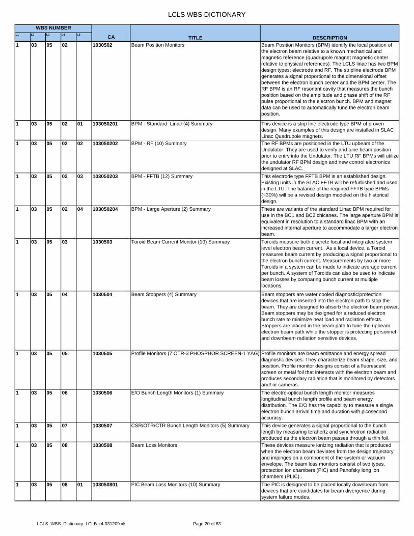
LCLS WBS DICTIONARY
L1 L2 L3 L4 L5 CA
WBS NUMBER
TITLE DESCRIPTION1 03 05 02 1030502 Beam Position Monitors Beam Position Monitors (BPM) identify the local position of
the electron beam relative to a known mechanical and magnetic reference (quadrupole magnet magnetic center relative to physical references). The LCLS linac has two BPM design types; electrode and RF. The stripline electrode BPM generates a signal proportional to the dimensional offset between the electron bunch center and the BPM center. The RF BPM is an RF resonant cavity that measures the bunch position based on the amplitude and phase shift of the RF pulse proportional to the electron bunch. BPM and magnet data can be used to automatically tune the electron beam position.
1 03 05 02 01 103050201 BPM - Standard Linac (4) Summary This device is a strip line electrode type BPM of proven design. Many examples of this design are installed in SLAC Linac Quadrupole magnets.
1 03 05 02 02 103050202 BPM - RF (10) Summary The RF BPMs are positioned in the LTU upbeam of the Undulator. They are used to verify and tune beam position prior to entry into the Undulator. The LTU RF BPMs will utilize the undulator RF BPM design and new control electronics designed at SLAC.
1 03 05 02 03 103050203 BPM - FFTB (12) Summary This electrode type FFTB BPM is an established design. Existing units in the SLAC FFTB will be refurbished and used in the LTU. The balance of the required FFTB type BPMs (~30%) will be a revised design modeled on the historical design.
1 03 05 02 04 103050204 BPM - Large Aperture (2) Summary These are variants of the standard Linac BPM required for use in the BC1 and BC2 chicanes. The large aperture BPM is equivalent in resolution to a standard linac BPM with an increased internal aperture to accommodate a larger electron beam.
1 03 05 03 1030503 Toroid Beam Current Monitor (10) Summary Toroids measure both discrete local and integrated system level electron beam current. As a local device, a Toroid measures beam current by producing a signal proportional to the electron bunch current. Measurements by two or more Toroids in a system can be made to indicate average current per bunch. A system of Toroids can also be used to indicate beam losses by comparing bunch current at multiple locations.
1 03 05 04 1030504 Beam Stoppers (4) Summary Beam stoppers are water cooled diagnostic/protection devices that are inserted into the electron path to stop the beam. They are designed to absorb the electron beam power.Beam stoppers may be designed for a reduced electron bunch rate to minimize heat load and radiation effects. Stoppers are placed in the beam path to tune the upbeam electron beam path while the stopper is protecting personnel and downbeam radiation sensitive devices.
1 03 05 05 1030505 Profile Monitors (7 OTR-3 PHOSPHOR SCREEN-1 YAG) Profile monitors are beam emittance and energy spread diagnostic devices. They characterize beam shape, size, and position. Profile monitor designs consist of a fluorescent screen or metal foil that interacts with the electron beam and produces secondary radiation that is monitored by detectors and/ or cameras.
1 03 05 06 1030506 E/O Bunch Length Monitors (1) Summary The electro-optical bunch length monitor measures longitudinal bunch length profile and beam energy distribution. The E/O has the capability to measure a single electron bunch arrival time and duration with picosecond accuracy.
1 03 05 07 1030507 CSR/OTR/CTR Bunch Length Monitors (5) Summary This device generates a signal proportional to the bunch length by measuring terahertz and synchrotron radiation produced as the electron beam passes through a thin foil.
1 03 05 08 1030508 Beam Loss Monitors These devices measure ionizing radiation that is produced when the electron beam deviates from the design trajectory and impinges on a component of the system or vacuum envelope. The beam loss monitors consist of two types, protection ion chambers (PIC) and Panofsky long ion chambers (PLIC)..
1 03 05 08 01 103050801 PIC Beam Loss Monitors (10) Summary The PIC is designed to be placed locally downbeam from devices that are candidates for beam divergence during system failure modes.
LCLS_WBS_Dictionary_LCLB_r4-031209.xls Page 20 of 63

LCLS WBS DICTIONARY
L1 L2 L3 L4 L5 CA
WBS NUMBER
TITLE DESCRIPTION1 03 05 09 1030509 Single Beam Dump (1) Summary The single beam dump is an electron beam stopper designed
to absorb the full beam energy. This dump is designed for system tuning and to provide protection for the undulator system in concert with a pulsed bend magnet.
1 03 05 10 1030510 Electron Beam Dump (1) Summary The electron beam dump is the endpoint for the electron beam in the LCLS system after the beam passes through the undulator system.
1 03 05 11 1030511 Protection Collimators (5) Summary Protection collimators are designed to limit the beam cross sectional dimensions in X and Y to prevent damage to devices downbeam from the collimator.
1 03 05 12 1030512 Movable Collimators (7x,3y) Summary Movable collimators are designed to tune the electron beam characteristics by limiting the beam dimension in either the X or Y axes.
1 03 05 13 1030513 Safety Electron Dump (1) Summary The safety electron dump is a redundant system designed to remove the electron beam in the event of a system failure mode.
1 03 06 10306 Linac RF Subsystem System Summary1 03 06 02 1030602 S-Band High Power System All of the new and modified RF power transmission parts
necessary to upgrade the Linac to the LCLS standard are included in this section. Layout for these components is charged to system integration for the particular LCLS functional area where the modification takes place. Parts found here are typically, S-Band waveguide straights and bends, pump outs, waveguide supports, and low energy couplers. Parts necessary to protect the linac during installation and/or store removed assemblies are included in this section.
1 03 06 03 1030603 S-Band Structures For LCLS, two existing 10 ft DLWG structures will be removed and be replaced by shortened sections (9.5 ft) to make room for LCLS optics or additional diagnostic devices. This section includes the cost to replace the 10 ft sections with existing 9.5 ft sections from current linac spares.
1 03 06 04 1030604 X-Band Low Level System The X-band RF system will be operated from the existing modulator and modified control system, which can adjust the phase and amplitude to within 10 picoseconds in phase and 2% in amplitude. A new feedback system will measure phase and amplitude of the beam, via BPMs and Bunch Length Monitors, process the information, and more precisely correct the phase and amplitude to meet LCLS specifications.
1 03 06 05 1030605 X-Band High Power System System Summary1 03 06 05 01 103060501 X-Band HP Klystron A conventional XL-4, X-Band klystron will be employed for
LCLS operation. This klystron model has shown it is capable of delivering 50 MW at 60 Hz and 1.6 us pulse lengths and it is not anticipated that running at 120 Hz and 0.1 us pulse lengths at a power of 25 MW for LCLS should be a problem for this tube.
1 03 06 05 02 103060502 X-Band HP Modulator The X-band modulator will comprise of an existing S-Band modulator, modified to to achieve as short a rise time as possible, to limit the average power from the klystron. A 19:1 turn ratio pulse transformer will enable the required 450 kV to be achieved from the standard 23.5 kV/6.7 kA modulator.
1 03 06 05 03 103060503 X-Band HP Waveguide System The system will use WR90 waveguide out of the klystron to a WR293 mode converter section, which will run from the gallery above straight down to the tunnel below. Once in the tunnel a mode converter will change back to WR90 and fed tothe RF structure. There will be three high power Bethe hole couplers in the system, one at the klystron output, one at the accelerator input, and one at the accelerator output. The coupler at the klystron output will be used to feed into the existing control system for the 21-2 klystron. The accelerator input and output couplers will be routed to the new RF feedback system.
LCLS_WBS_Dictionary_LCLB_r4-031209.xls Page 21 of 63

LCLS WBS DICTIONARY
L1 L2 L3 L4 L5 CA
WBS NUMBER
TITLE DESCRIPTION1 03 06 06 1030606 X-Band Structures The structure that will be used will be a NLCTA type 60cm
long traveling wave structure, whose shunt impedance is of the order of 30 MOhms/m. The 7.2mm diameter aperture of this structure will be the limiting aperture in the main linac andinterception of high power End Station beams could be damaging. Therefore, removal of the structure, either automatic or manual, during high power End Station running is foreseen.
1 03 06 07 1030607 RF Distribution System System Summary1 03 06 07 01 103060701 Modulator Refurbishment Not all modulators in the linac are stable enough to enable the
RF output of a 5045 klystron to meet LCLS specifications. The critical stations used in feedback and for L1 will require the stability of the best linac modulators. Most of the voltage jitter is believed to be coming from the thyratron. The modulators will be refurbished and have new thyratrons installed.
1 03 06 07 02 103060702 Solid State Sub Booster The Solid State Sub-Booster (SSSB) is a pulsed amplifier with 600W out and is used to drive a 5045 klystron. With 50dB of gain the unit can be driven from the LLRF system with 10mW input power levels. Klystrons with SSSBs can be controlled independent of other klystrons in the sector on a pulse to pulse basis. PED for this unit is done in the injector budget.
1 03 06 07 06 103060706 RF Phase Measurements Modifications to the S-band Phase and Amplitude Detector (PAD) are required to run the X-band system with the existing control system. This task will include modifications internal to an existing PAD or development of a new PAD with compatible IO.
1 03 06 07 07 103060707 RF Distribution L2 & L3 The existing RF distribution system is not accurate to LCLS specifications. A new reference line running the last kilometerof the accelerator in the temperature stabilized tunnel will improve stability an order of magnitude, relaxing the requirements of the feedback systems.
1 03 07 10307 Linac Installation & Alignment This WBS section covers the reception of parts, components, and sub assemblies from either a Post Processing & Testing or a Rack Integration activity. Installation begins at beneficial occupancy or at a planned SLAC Linac downtime and completes all necessary activities prior to the start of commissioning. These activities are, but not limited to, mechanical installation of beam line components, installation of vacuum components, alignment, vacuum pump down, vacuum leak checking and functional testing of components and all of their respective control systems. Management of project installation activities are not covered in this section. Those activities are covered under WBS 1.3.1, System Management & Integration. This WBS section also covers the removal and/or relocation of existing SLAC Linac beam line components to make room for new LCLS Linac components such as magnets, vacuum components, RF components and diagnostic instruments.
1 03 07 01 1030701 Linac L01 System Installation & Alignment This WBS section identifies and collects the resources and costs associated with the removal and/or relocation of SLAC Linac beam line components and the installation and relocation of all LCLS Linac beam line components in accordance with the activity description above. This section also accounts for the shortening of the existing SLAC Linac accelerator structures in SLAC Linac Sector 21.
1 03 07 02 1030702 Linac BC1 System Installation & Alignment This WBS section identifies and collects the resources and costs associated with the removal of SLAC Linac beam line components and the installation of all BC1 components in accordance with the activity description above.
1 03 07 05 1030705 Linac L03 System Installation & Alignment This WBS section identifies and collects the resources and costs associated with the removal and/or relocation of SLAC Linac beam line components and the installation of all LCLS Linac beam line components in accordance with the activity description above.***Moved to 1.03.07.20****
LCLS_WBS_Dictionary_LCLB_r4-031209.xls Page 22 of 63
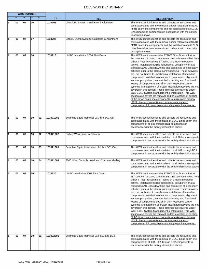
LCLS WBS DICTIONARY
L1 L2 L3 L4 L5 CA
WBS NUMBER
TITLE DESCRIPTION1 03 07 06 1030706 Linac LTU System Installation & Alignment This WBS section identifies and collects the resources and
costs associated with the removal and/or relocation of SLAC FFTB beam line components and the installation of all LCLS Linac beam line components in accordance with the activity description above.
1 03 07 07 1030707 Linac E-Dump System Installation & Alignment This WBS section identifies and collects the resources and costs associated with the removal and/or relocation of SLAC FFTB beam line components and the installation of all LCLS Linac beam line components in accordance with the activity description above.
1 03 07 10 1030710 LINAC Installation 2006 Shut Down This WBS section covers the FY2006 Shut Down effort for the reception of parts, components, and sub assemblies from either a Post Processing & Testing or a Rack Integration activity. Installation begins at beneficial occupancy or at a planned SLAC Linac downtime and completes all necessary activities prior to the start of commissioning. These activities are, but not limited to, mechanical installation of beam line components, installation of vacuum components, alignment, vacuum pump down, vacuum leak checking and functional testing of components and all of their respective control systems. Management of project installation activities are not covered in this section. Those activities are covered under WBS 1.3.1, System Management & Integration. This WBS section also covers the removal and/or relocation of existing SLAC Linac beam line components to make room for new LCLS Linac components such as magnets, vacuum components, RF components and diagnostic instruments.
1 03 07 10 01 103071001 Beamline Equip Removal L01 thru BC1 Out This WBS section identifies and collects the resources and costs associated with the removal of SLAC Linac beam line components of all L01 through BC1 components in accordance with the activity description above.
1 03 07 10 02 103071002 Gallery Waveguide Installation This WBS section identifies and collects the resources and costs associated with the installation of all Gallery Waveguide components in accordance with the activity description above.
1 03 07 10 03 103071003 Beamline Equip Installation L01 thru BC1 Out This WBS section identifies and collects the resources and costs associated with the installation of all L01 through BC1 components in accordance with the activity description above.
1 03 07 10 04 103071004 2006 Linac Controls Install and Checkout Gallery This WBS section identifies and collects the resources and costs associated with the installation of all Gallery Waveguide components in accordance with the activity description above.
1 03 07 20 1030720 LINAC Installation 2007 Shut Down This WBS section covers the FY2007 Shut Down effort for the reception of parts, components, and sub assemblies from either a Post Processing & Testing or a Rack Integration activity. Installation begins at beneficial occupancy or at a planned SLAC Linac downtime and completes all necessary activities prior to the start of commissioning. These activities are, but not limited to, mechanical installation of beam line components, installation of vacuum components, alignment, vacuum pump down, vacuum leak checking and functional testing of components and all of their respective control systems. Management of project installation activities are not covered in this section. Those activities are covered under WBS 1.3.1, System Management & Integration. This WBS section also covers the removal and/or relocation of existing SLAC Linac beam line components to make room for new LCLS Linac components such as magnets, vacuum components, RF components and diagnostic instruments.
1 03 07 20 01 103072001 Beamline Equip Removal L02, L03 and BC2 This WBS section identifies and collects the resources and costs associated with the removal of SLAC Linac beam line components of all L01, L02 through BC2 components in accordance with the activity description above.
LCLS_WBS_Dictionary_LCLB_r4-031209.xls Page 23 of 63

LCLS WBS DICTIONARY
L1 L2 L3 L4 L5 CA
WBS NUMBER
TITLE DESCRIPTION1 03 07 20 02 103072002 Beamline Equip Installation L02, L03 and BC2 This WBS section identifies and collects the resources and
costs associated with the installation of all Gallery Waveguide components in accordance with the activity description above.
1 03 07 20 03 103072003 2007 Linac Controlls Install and Checkout This WBS section identifies and collects the resources and costs associated with the installation and checkout of all 2007 Linac Controls in accordance with the activity description above.
1 03 07 20 04 103072004 Linac Undulator Interface This WBS section identifies and collects the resources and costs associated with the installation of all Undulator Interfacewith Linac in accordance with the activity description above.
1 04 104 UNDULATOR SYSTEM The LCLS Undulator System Project Costs, including undulator magnets and supports, undulator diagnostics, vacuum systems, and controls for the undulator equipment are included herein. Integration and installation are also included within this area. Total cost for the LCLS undulator system planning, project management, design, construction, and installation are summed at this level.
1 04 01 10401 Undulator System Management & Integration All project management and engineering integration oversight is covered by this element. Total cost of all project management and project integration tasks required to design, construct, test and install an operationally complete undulator system for the LCLS: Undulator System Management; ANL Project Support; Undulator System M&S – General; UndulatorSystem Reviews and Workshops.
1 04 01 01 1040101 Undulator System Management Oversee project management details and delivery of a completely operational undulator system for the LCLS. This section includes all project management and project integration tasks required to design, construct, test and install an operationally complete undulator system for the LCLS: Undulator System Management-Technical; ANL Project Support-General.
1 04 01 01 01 104010101 Undulator System Management - Technical Oversee the technical project management details and delivery of a completely operational undulator system for the LCLS. Technical management and oversight cost of all project management and project integration tasks required to design, construct, test and install an operationally complete undulator system for the LCLS. It also include SLAC indirect costs generated as a part of doing business with ANL.
1 04 01 01 02 104010102 ANL Project Support Provide all necessary administrative, PMCS, budget, schedule, and contract monitoring, website and other basic sundry support required for the delivery of a completely operational undulator system for the LCLS. This section includes direct and indirect ANL LCLS project support costs required to design, construct, test, and install an operationally complete undulator system for the LCLS.
1 04 01 02 1040102 Undulator System Materials & Supplies This section covers the total M&S cost of the ANL LCLS project office required during the design, construction, testing and installation of an operationally complete undulator systemfor the LCLS.
1 04 01 02 01 104010201 Undulator System M&S - General Basic M&S cost excluding travel of the ANL LCLS project office required during the design, construction, testing and installation of an operationally complete undulator system for the LCLS: Office supplies and miscellaneous materials; Tele/video conferencing; CPUs and Software; Shipping and Storage.
1 04 01 02 02 104010202 Undulator System Travel Basic M&S cost of travel for the ANL LCLS project required during the design, construction, testing and installation of an operationally complete undulator system for the LCLS.
LCLS_WBS_Dictionary_LCLB_r4-031209.xls Page 24 of 63

LCLS WBS DICTIONARY
L1 L2 L3 L4 L5 CA
WBS NUMBER
TITLE DESCRIPTION1 04 01 03 1040103 Undulator System Reviews and Workshops This section provides the necessary support for all reviews of
the undulator system or required workshops. It includes all costs required to cover all semiannual reviews and occasionalworkshops focused on the needs of the LCLS undulator system: Organization and management of all LCLS undulator system reviews and related workshops; Travel for reviewers or necessary workshop attendees; Miscellaneous items required during the reviews and workshops.
1 04 02 10402 Controls Overall undulator controls task covers all controls issues involved with the LCLS undulator. This includes the costs involved with the entire controls section of the LCLS undulator. It also consists of the specification, design, procurement, assembly and testing of all controls components of the LCLS undulator.
1 04 02 01 1040201 Controls Management and Integration Management and Integration of the Undulator controls activities.
1 04 02 01 03 104020103 Software Interface with SLAC This is the Cost Center for the software design effort required for high-level control applications which will interface with the SLAC control system. Includes commercial software required for design and implementation of these applications. The high level software is that which the operators and scientists in charge of the LCLS use to interact with the undulators. By necessity, this software must function in a dual control systemenvironment (LCLS and SLAC).
1 04 02 01 04 104020104 Undulator Cable, Tray, and Rack Layout This is the Cost Center for the design effort required to generate a plan for the equipment location, layout and distribution within the undulator hall. All components connected via cable to equipment located in racks must be accounted for, and estimates on cable lengths and locations will be made.
1 04 02 01 05 104020105 Miscellaneous Controls This element includes miscellaneous tasks that do not fit into all the other controls effort WBS elements. Significant items are all vacuum pump equipment including pumps, controls, and cabling.
1 04 02 02 1040202 Motion This element tracks any controls effort and materials for motion within the LCLS undulator hall. This consists of all controls effort and materials required to control motion based component within the LCLS undulator.
1 04 02 02 01 104020201 Undulator Cam Movers This element covers effort and materials costs for the cam mover system.
1 04 02 02 02 104020202 Motion Test Stand In order to test certain controls aspect of the undulator motion, a test stand will be assembled to evaluate a variety of motion parameters. This cost center will cover the design and procurement of these components.
1 04 02 02 06 104020206 Scanning Wire Motion The motion of the scanning wire element is contained within this element. This covers the controls effort and costs involved in the motion of the scanning wire transducer. (descoped)
1 04 02 02 07 104020207 Translation Stage Motion This element covers effort and materials costs for the undulator translation stage mechanism.
1 04 02 03 1040203 Signal Analysis This element includes all signal analysis done for data acquisition and beam analysis within the LCLS undulator. All signal acquisition hardware and software for signal analysis isincluded in this element. Effort for data analysis and control is also included.
1 04 02 03 01 104020301 RFBPM This element consists of the hardware and software required to interface the RFBPM units to the control system. All hardware and software required for interfacing the RFBPM units to the control system is included within this element. This includes the timing interface, signal acquisition and control software.
1 04 02 03 03 104020303 Beam Finder Wire This element covers the integration of the beam finder wire into the undulator control system.
1 04 02 04 1040204 Video The costs to develop and OTR Monitor and video for the undulator system.
1 04 02 04 01 104020401 OTR Monitor The cost to develop an OTR monitor for the undulator system.
1 04 02 04 03 104020403 Observation Station Video The cost to develop video for the undulator system.
LCLS_WBS_Dictionary_LCLB_r4-031209.xls Page 25 of 63

LCLS WBS DICTIONARY
L1 L2 L3 L4 L5 CA
WBS NUMBER
TITLE DESCRIPTION1 04 02 05 1040205 Data Acquisition and Control This element covers the various I/O that is not covered in
previous elements but is a part of the control system. In general the costs underneath this section are effort only. If hardware is required, it is typically for reading of discrete signals. This consists of the specification and integration of general signals into the control system.
1 04 02 05 01 104020501 Strongback Temperature Monitoring Consists of the software required to communicate to the strongback temperature probes. The costs cover the effort involved in interfacing the strongback temperature monitoring equipment to the undulator control system. This consists mainly of effort involved in creating software to talk to the temperature equipment.
1 04 02 06 1040206 Vacuum This is the overall element covering any controls tasks involved in interfacing the vacuum equipment. This is a parentto the other (specific) vacuum controls tasks. It consists of software effort to interface commercial vacuum components.
1 04 02 06 01 104020601 Ion Pump Controller This element covers the costs of developing the installation and layout plan for the ion pump controllers of the undulator system.
1 04 02 07 1040207 Machine Protection All MPS components and effort will fall under this category. The MPS system is responsible for protecting the undulator hall from equipment damage. It must interface to the SLAC injector to cause a beam abort in event of a failure.
1 04 02 07 01 104020701 Undulator Beam Loss Monitor Controls All effort and materials devoted to the undulator beam loss monitor controls will be tracked within this element. The beam loss monitor generates a signal which must be processed to interface to the machine protection system.
1 04 02 08 1040208 Undulator Magnet Power Supplies This element covers design of the power supply controls software, documentation, construction of the computer interface, and integration. It also covers all costs of purchasing the power supplies and controls for them.
1 04 02 10 1040210 Undulator Control Module This is the cost center for the effort to design and procure the undulator control module. It includes the design and purchaseof the components.
1 04 02 12 1040212 Rack and Cable This is the cost center for the specification and purchase of the intra-undulator racks and cables for the in-tunnel equipment.
1 04 02 13 1040213 BPM This is the cost center used to support the design and development of the RF Cavity BPM. It includes engineering effort for software design used to charaterize the BPM electronics.
1 04 02 14 1040214 Long Term Test Prep This is the cost center used to design and deploy the cabling and controls electronics for the long-term test fixture at APS.
1 04 02 17 1040217 Undulator Conrols - Management This is the const center used to cover effort and expenses associated with the management of the undulator controls effort.
1 04 02 20 1040220 Undulator MPS Machine Protection System for the undulator installed and tested.
1 04 02 21 1040221 Undulator Controls - Timing The timing system providing the rates and triggers installed and tested.
1 04 02 22 1040222 Undulator Controls - BPM The beam position monitor data acquisition electronics and software installed.
1 04 02 23 1040223 Undulator Controls - Vacuum The vacuum controls and monitoring hardware and software installed.
1 04 02 24 1040224 Undulator Controls - ADS System The undulator diagnostics including WPM and HLS installed and tested.
1 04 03 10403 Undulator Magnet & Support This element covers the LCLS undulator magnets and supports, including calibration, assembly, and integration.
1 04 03 01 1040301 UND Magnet & Support - Mgmt and Integration Integration of the undulator design, construction, installation, and commissioning efforts.
LCLS_WBS_Dictionary_LCLB_r4-031209.xls Page 26 of 63
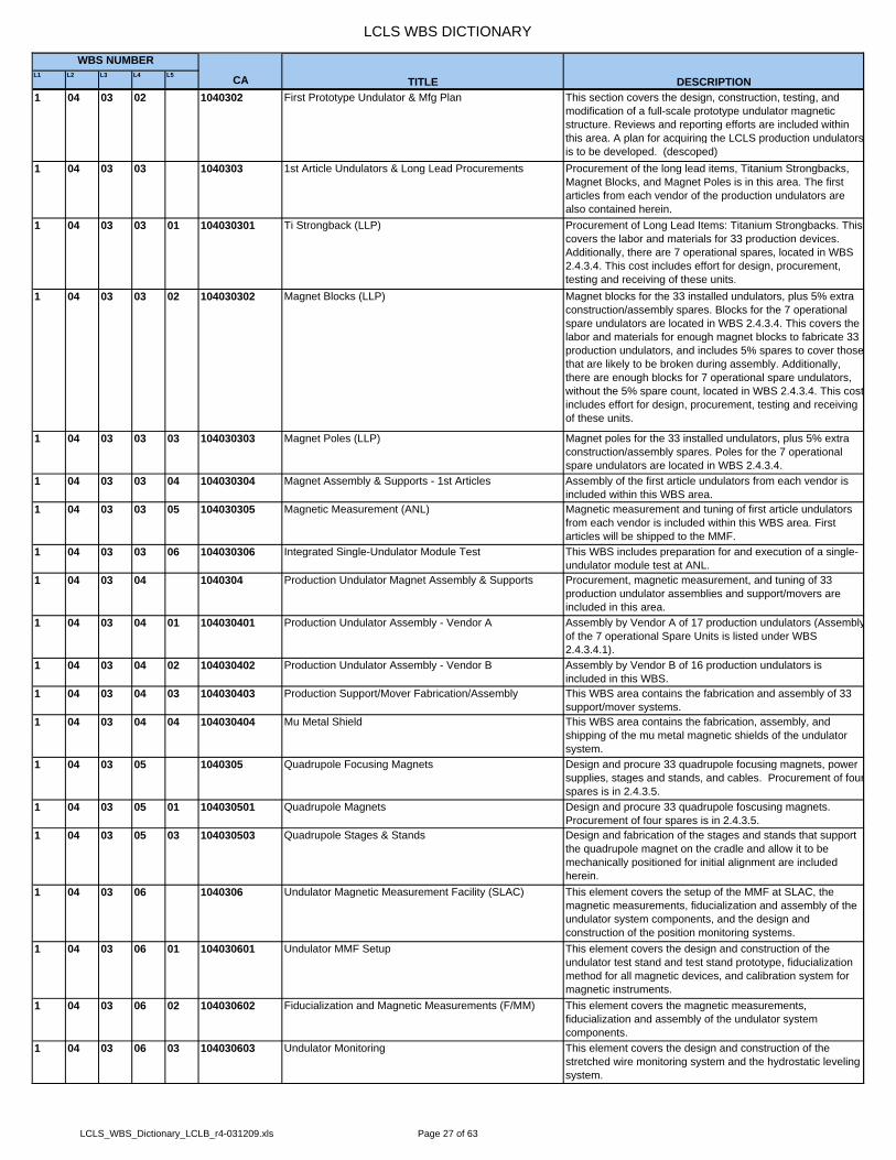
LCLS WBS DICTIONARY
L1 L2 L3 L4 L5 CA
WBS NUMBER
TITLE DESCRIPTION1 04 03 02 1040302 First Prototype Undulator & Mfg Plan This section covers the design, construction, testing, and
modification of a full-scale prototype undulator magnetic structure. Reviews and reporting efforts are included within this area. A plan for acquiring the LCLS production undulatorsis to be developed. (descoped)
1 04 03 03 1040303 1st Article Undulators & Long Lead Procurements Procurement of the long lead items, Titanium Strongbacks, Magnet Blocks, and Magnet Poles is in this area. The first articles from each vendor of the production undulators are also contained herein.
1 04 03 03 01 104030301 Ti Strongback (LLP) Procurement of Long Lead Items: Titanium Strongbacks. This covers the labor and materials for 33 production devices. Additionally, there are 7 operational spares, located in WBS 2.4.3.4. This cost includes effort for design, procurement, testing and receiving of these units.
1 04 03 03 02 104030302 Magnet Blocks (LLP) Magnet blocks for the 33 installed undulators, plus 5% extra construction/assembly spares. Blocks for the 7 operational spare undulators are located in WBS 2.4.3.4. This covers the labor and materials for enough magnet blocks to fabricate 33 production undulators, and includes 5% spares to cover thosethat are likely to be broken during assembly. Additionally, there are enough blocks for 7 operational spare undulators, without the 5% spare count, located in WBS 2.4.3.4. This costincludes effort for design, procurement, testing and receiving of these units.
1 04 03 03 03 104030303 Magnet Poles (LLP) Magnet poles for the 33 installed undulators, plus 5% extra construction/assembly spares. Poles for the 7 operational spare undulators are located in WBS 2.4.3.4.
1 04 03 03 04 104030304 Magnet Assembly & Supports - 1st Articles Assembly of the first article undulators from each vendor is included within this WBS area.
1 04 03 03 05 104030305 Magnetic Measurement (ANL) Magnetic measurement and tuning of first article undulators from each vendor is included within this WBS area. First articles will be shipped to the MMF.
1 04 03 03 06 104030306 Integrated Single-Undulator Module Test This WBS includes preparation for and execution of a single-undulator module test at ANL.
1 04 03 04 1040304 Production Undulator Magnet Assembly & Supports Procurement, magnetic measurement, and tuning of 33 production undulator assemblies and support/movers are included in this area.
1 04 03 04 01 104030401 Production Undulator Assembly - Vendor A Assembly by Vendor A of 17 production undulators (Assemblyof the 7 operational Spare Units is listed under WBS 2.4.3.4.1).
1 04 03 04 02 104030402 Production Undulator Assembly - Vendor B Assembly by Vendor B of 16 production undulators is included in this WBS.
1 04 03 04 03 104030403 Production Support/Mover Fabrication/Assembly This WBS area contains the fabrication and assembly of 33 support/mover systems.
1 04 03 04 04 104030404 Mu Metal Shield This WBS area contains the fabrication, assembly, and shipping of the mu metal magnetic shields of the undulator system.
1 04 03 05 1040305 Quadrupole Focusing Magnets Design and procure 33 quadrupole focusing magnets, power supplies, stages and stands, and cables. Procurement of fourspares is in 2.4.3.5.
1 04 03 05 01 104030501 Quadrupole Magnets Design and procure 33 quadrupole foscusing magnets. Procurement of four spares is in 2.4.3.5.
1 04 03 05 03 104030503 Quadrupole Stages & Stands Design and fabrication of the stages and stands that support the quadrupole magnet on the cradle and allow it to be mechanically positioned for initial alignment are included herein.
1 04 03 06 1040306 Undulator Magnetic Measurement Facility (SLAC) This element covers the setup of the MMF at SLAC, the magnetic measurements, fiducialization and assembly of the undulator system components, and the design and construction of the position monitoring systems.
1 04 03 06 01 104030601 Undulator MMF Setup This element covers the design and construction of the undulator test stand and test stand prototype, fiducialization method for all magnetic devices, and calibration system for magnetic instruments.
1 04 03 06 02 104030602 Fiducialization and Magnetic Measurements (F/MM) This element covers the magnetic measurements, fiducialization and assembly of the undulator system components.
1 04 03 06 03 104030603 Undulator Monitoring This element covers the design and construction of the stretched wire monitoring system and the hydrostatic leveling system.
LCLS_WBS_Dictionary_LCLB_r4-031209.xls Page 27 of 63
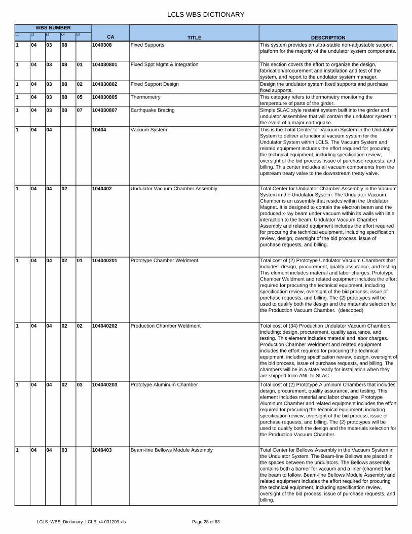
LCLS WBS DICTIONARY
L1 L2 L3 L4 L5 CA
WBS NUMBER
TITLE DESCRIPTION1 04 03 08 1040308 Fixed Supports This system provides an ultra-stable non-adjustable support
platform for the majority of the undulator system components.
1 04 03 08 01 104030801 Fixed Sppt Mgmt & Integration This section covers the effort to organize the design, fabrication/procurement and installation and test of the system, and report to the undulator system manager.
1 04 03 08 02 104030802 Fixed Support Design Design the undulator system fixed supports and purchase fixed supports.
1 04 03 08 05 104030805 Thermometry This category refers to thermometry monitoring the temperature of parts of the girder.
1 04 03 08 07 104030807 Earthquake Bracing Simple SLAC style restaint system built into the girder and undulator assemblies that will contain the undulator system in the event of a major earthquake.
1 04 04 10404 Vacuum System This is the Total Center for Vacuum System in the Undulator System to deliver a functional vacuum system for the Undulator System within LCLS. The Vacuum System and related equipment includes the effort required for procuring the technical equipment, including specification review, oversight of the bid process, issue of purchase requests, and billing. This center includes all vacuum components from the upstream treaty valve to the downstream treaty valve.
1 04 04 02 1040402 Undulator Vacuum Chamber Assembly Total Center for Undulator Chamber Assembly in the Vacuum System in the Undulator System. The Undulator Vacuum Chamber is an assembly that resides within the Undulator Magnet. It is designed to contain the electron beam and the produced x-ray beam under vacuum within its walls with little interaction to the beam. Undulator Vacuum Chamber Assembly and related equipment includes the effort required for procuring the technical equipment, including specification review, design, oversight of the bid process, issue of purchase requests, and billing.
1 04 04 02 01 104040201 Prototype Chamber Weldment Total cost of (2) Prototype Undulator Vacuum Chambers that includes: design, procurement, quality assurance, and testing.This element includes material and labor charges. Prototype Chamber Weldment and related equipment includes the effortrequired for procuring the technical equipment, including specification review, oversight of the bid process, issue of purchase requests, and billing. The (2) prototypes will be used to qualify both the design and the materials selection for the Production Vacuum Chamber. (descoped)
1 04 04 02 02 104040202 Production Chamber Weldment Total cost of (34) Production Undulator Vacuum Chambers including: design, procurement, quality assurance, and testing. This element includes material and labor charges. Production Chamber Weldment and related equipment includes the effort required for procuring the technical equipment, including specification review, design, oversight ofthe bid process, issue of purchase requests, and billing. The chambers will be in a state ready for installation when they are shipped from ANL to SLAC.
1 04 04 02 03 104040203 Prototype Aluminum Chamber Total cost of (2) Prototype Aluminum Chambers that includes: design, procurement, quality assurance, and testing. This element includes material and labor charges. Prototype Aluminum Chamber and related equipment includes the effort required for procuring the technical equipment, including specification review, oversight of the bid process, issue of purchase requests, and billing. The (2) prototypes will be used to qualify both the design and the materials selection for the Production Vacuum Chamber.
1 04 04 03 1040403 Beam-line Bellows Module Assembly Total Center for Bellows Assembly in the Vacuum System in the Undulator System. The Beam-line Bellows are placed in the spaces between the undulators. The Bellows assembly contains both a barrier for vacuum and a liner (channel) for the beam to follow. Beam-line Bellows Module Assembly and related equipment includes the effort required for procuring the technical equipment, including specification review, oversight of the bid process, issue of purchase requests, and billing.
LCLS_WBS_Dictionary_LCLB_r4-031209.xls Page 28 of 63

LCLS WBS DICTIONARY
L1 L2 L3 L4 L5 CA
WBS NUMBER
TITLE DESCRIPTION1 04 04 03 01 104040301 Prototype Bellows Module Total cost of (3) Prototype Bellows Modules including: design,
procurement, quality assurance, and testing. This element includes material and labor charges. The (3) prototypes will be used to qualify both the design and the materials selection for the Production Bellows Module.
1 04 04 03 02 104040302 Production Bellows Module Total cost of (47) Production Bellows Modules including: design, procurement, quality assurance, and testing. This element includes material and labor charges. The (47) Production Bellows Modules will be used in the Short and Long Diagnostics Breaks along with the Entrance and Exit Sections.
1 04 04 04 1040404 Single Undulator Test (SUT) Vacuum Total cost of Vacuum Components to be used in the Single Undulator Test including: design, procurement, and quality assurance. This element includes material and labor charges. These are the temporary units that will be used until actual units are available.
1 04 04 05 1040405 Short Diagnostic Break (SDB) Assembly Total Center for (23) Short Diagnostic Break Assembly in the Vacuum System in the Undulator System. This center includes: design, procurement, quality assurance, and testing.This element includes material and labor charges. The Short Diagnostics Break is that set of vacuum components that reside within the smaller breaks between the undulator magnets. This is also the assembly that includes both diagnostics devices and vacuum components, although the costing of these items will be found in other places in the WBS.
1 04 04 06 1040406 Long Diagnostic Break (LDB) Assembly Total Center for (11) Long Diagnostic Break Assembly in the Vacuum System in the Undulator System. The Long Diagnostics Break is that set of vacuum components that reside within the larger breaks between the undulator magnets.
1 04 04 07 1040407 Entrance Section Assembly Specification of the vacuum system requirements at the entrance to the undulator system.
1 04 04 08 1040408 Exit Section Assembly Specification of the vacuum system requirements at the exit to the undulator system.
1 04 04 09 1040409 Baking System Total Center for Baking System in the Vacuum System in the Undulator System. This element covers the labor and materials for the baking system for vacuum components going into the undulator vacuum system. This includes effort for design, procurement, and receiving of these units. Baking System and related equipment includes the effort required for procuring the technical equipment, including specification review, oversight of the bid process, issue of purchase requests, and billing.
1 04 05 10405 Diagnostics Deliver a functional Diagnostics for the Undulator System within LCLS. This center includes all diagnostics devices from the upstream treaty valve to the downstream treaty valve.
1 04 05 02 1040502 Undulator Line Diagnostics (ULD) Total Center for the Undulator Line Diagnostics for the Undulator System. This element covers the labor and materials for this center. This includes effort for design, procurement, testing and receiving of the units. This center contains the intra-undulator diagnostics that reside within the diagnostics station that are placed in the (11) Long Diagnostics Breaks.
1 04 05 02 01 104050201 ULD Test Station This element covers the labor and materials for making the (1) ULD Test Station. This includes effort for design, procurement, testing and receiving of this unit. The Test Station will be used along with the prototypes of the scanning wire, OTR, x-ray imaging, x-ray intensity, and monochromator to test the sub-systems in a beam line. (descoped)
1 04 05 02 02 104050202 ULD Vacuum Chamber This element covers the labor and materials for the group of (11) production vacuum chambers. This includes effort for design, procurement, testing and receiving of the units. The ULD Vacuum Chamber is the housing where the production type ULD Diagnostics are contained. (descoped)
LCLS_WBS_Dictionary_LCLB_r4-031209.xls Page 29 of 63

LCLS WBS DICTIONARY
L1 L2 L3 L4 L5 CA
WBS NUMBER
TITLE DESCRIPTION1 04 05 02 03 104050203 Positioning Mechanism The Positioning Mechanism is a device for moving from one
diagnostic device to another within the EBXPD Diagnostics Station. This cost element covers the labor and materials for prototype related work and the group of (11) production devices. This includes effort for design, procurement, testing and receiving of the units. (descoped)
1 04 05 02 04 104050204 Scanning wire assembly (ULD-SWA) The Scanning Wire, also called wire scanner, will be used to measure the overlap of the undulator line diagnostics. (descoped)
1 04 05 02 05 104050205 Optical transition radiation imaging assembly The OTR is used to produce an image of the electron beam to characterize its size and shape, this is needed for beam tuning purposes. This element covers the labor and materials for prototype related work and the group of (11) production devices. This includes effort for design, procurement, testing and receiving of the units. (descoped)
1 04 05 04 1040504 End-of-Undulator(EOU) X-ray and Profile diagnost The End of Undulator Diagnostics is an important area where studies and simulations are being conducted to best utilize the area. Total Center for the End-of-Undulator Diagnostics for the Undulator System. There will be just a single suite of EOU diagnostics.This is a LOE task with a small amount of M&S devoted to the development of a suite of end-of-undulator diagnostics.
1 04 05 04 01 104050401 Prototype Construction and Testing This element covers the labor and materials for the fixtures related to testing the (1) EOU prototype. This includes effort for design, procurement, testing and receiving of the fixtures and test pieces for the EOU prototype test.
1 04 05 05 1040505 RFBPM The RFBPM will be used to precisely measure the position of the electron beam in all the breaks between the undulators. Total Center for RFBPM Diagnostics for the Undulator System.
1 04 05 05 01 104050501 X-Band Cavity BPM Development The X Band Cavity BPM is the sensor installed in the beam line that will be used to precisely measure the position of the electron beam in all the breaks between the undulators. Total Center for RFBPM Diagnostics for the Undulator System. This element covers the labor and materials for (5) prototypes: (1) non-vacuum bench unit, (1) ITS beam test unit, and (3) for single shot test. This includes effort for design, procurement, testing and receiving of the units.
1 04 05 05 02 104050502 X-Band Receiver Development The X-Band Receiver takes the signals from the RFBPM cavity and down converts to a lower frequency signal. Total Center for X-Band Receiver Prototype activities for the Undulator System. This element covers the labor and materials for (4) prototypes: (1) for the ITS test and (3) for the single shot test. This includes effort for design, procurement, testing and receiving of the units.
1 04 05 05 03 104050503 X-Band BPM Production This element represents the production of the RFBPM system. It incompasses the production of the cavities, receivers, waveguides and supports. This element covers thelabor and materials for (8) units going into the LTU and a group of (35) devices going into the Undulator System. This includes effort for design, procurement, testing and receiving of the units.
1 04 05 06 1040506 Beam Finder Wire The Beam Finder Wire will be used to precisely measure the position of the electron beam in all the breaks between the undulators. Total Center for Beam Finder Wire Diagnostics for the Undulator System. This element covers the labor and materials for prototype effort and a group of (33) production devices. This includes effort for design, procurement, testing and receiving of the units.
1 04 05 07 1040507 Charge Monitor (CM) Review of SLAC Charge Monitor Design.1 04 05 08 1040508 Beam Loss Monitoring This element cover the design and materials costs for the
beam loss monitor system installed in the undulator system and used to protect it from significant radiation doses.
LCLS_WBS_Dictionary_LCLB_r4-031209.xls Page 30 of 63

LCLS WBS DICTIONARY
L1 L2 L3 L4 L5 CA
WBS NUMBER
TITLE DESCRIPTION1 04 05 08 1040508 Beam Loss Monitoring (cont) Radiation Detection Monitor is a gamma ray detector and is
part of the machine protection system. RDM and related equipment includes the effort required for procuring the technical equipment, including specification review, oversight of the bid process, issue of purchase requests, and billing. This element covers the labor and materials for a single (1) production device. This includes effort for design, procurement, testing and receiving of this unit.
1 04 05 10 1040510 Single Undulator Test (SUT) Diagnostics Total cost of Diagnostic Components to be used in the Single Undulator Test including: design, procurement, and quality assurance. This element includes material and labor charges. These are the temporary units that be used until actual units are available.
1 04 06 10406 Undulator System Installation and Alignment This element covers all the M&S and effort, management oversight, technical and other labor, required for the LCLS undulator system installation, basic checkout, and alignment tasks. Following beneficial occupancy (BO) of the LCLS Undulator Hall all technical equipment, fixed supports, undulators and quadrupole magnets, diagnostics, vacuum systems, and controls system, will be moved into the undulator hall, installed, checked out, and aligned to the required position and accuracy.
1 04 06 02 1040602 Control System Installation and Alignment The control system installation will be done as the pieces to be controlled are installed - in a phased approach. Checkout will be done when specific modules are in place and testing will be productive. All costs involved in the installation and checkout of the undulator control system will be tracked withinthis element.
1 04 06 04 1040604 Vacuum System Installation and Alignment This element contains the individual effort for transporting the vacuum system into the LCLS undulator tunnel and installing the different vacuum components in the Undulator System. Installation, integration, and checkout of bellows, pumps, vacuum gauges, residual gas analyzers, pump-out valves, and gate valves will be worked on in this element. Total Center for the installation of the Vacuum System in the Undulator System at SLAC. This element covers the labor for vacuum components going into the undulator vacuum system.
1 04 06 06 1040606 2008 Undulator System Installation This element is the total cost center for all M&S and effort, management oversight, technical and other labor, required forthe LCLS undulator system installation, basic checkout, and alignment tasks. Following beneficial occupancy (BO) of the LCLS Undulator Hall all technical equipment, fixed supports, undulators and quadrupole magnets, diagnostics, vacuum systems, and controls system, will be moved into the undulator hall, installed, checked out, and aligned to the required position and accuracy.
1 05 105 X-RAY TRANSPORT & DIAGNOSTICS SYSTEMS XTOD includes mechanical and vacuum systems for the x-raybeam path, attenuators, x-ray optics and x-ray diagnostics required for manipulation and characterization of the x-ray beam downstream of the undulator. “Manipulation” includes collimation, attenuation, turning, and monochromatizing. “Characterization” includes measurement of x-ray beam properties as necessary for commissioning and operation of the LCLS.
1 05 01 10501 System Management & Integration This element provides overall management for XTOD.1 05 01 01 1050101 Management This element provides overall management for XTOD safety,
conceptualization, R&D, design, construction, testing, installation, integration, and commissioning.
1 05 01 01 01 105010101 XTOD Management - Technical This covers a full time manager.1 05 01 01 02 105010102 LLNL Project Support This covers a half time administrator, and funding for
programmatic travel to attend weekly staff meetings, recruit project staff prepare monthly reports, prepare reviews, and other required project documentation.
1 05 01 01 03 105010103 Commissioning Coordinator This element provides support to develop a schedule for installation, testing, and commissioning activities for X-Ray Transport. Also, the work must be coordinated with X-Ray Endstations as well as other LCLS subprojects.
LCLS_WBS_Dictionary_LCLB_r4-031209.xls Page 31 of 63

LCLS WBS DICTIONARY
L1 L2 L3 L4 L5 CA
WBS NUMBER
TITLE DESCRIPTION1 05 02 10502 Controls Controls captures upper-level work required to interface and
integrate the LCLS system-wide control systems to the XTOD primitive controls and to provide remote access to the instrumentation in the Front End Enclosure (FEE), the Near Experimental Hall (NEH), the Tunnel, and the Far Experimental Hall (FEH).
1 05 02 01 1050201 Controls This element covers the development and delivery of the EPICS control system for XTOD. This will include the development of high level application programming to supportthe physics application and software programs for all XTOD diagnosics and instruments. The control system will interface to a variety of devices including cameras, sensor electronics, valves, motors, and gas flow and pressure controllers.
1 05 02 02 1050202 Controls - Motors This element covers the initial specification, design and material list evaluation for the motors in the X-Ray Transport control system.
1 05 02 03 1050203 Controls - Vacuum Design pumps, pipes and stands for interconnecting the experimental tanks in the FEE, Near Hall, Tunnel and Far Hall.
1 05 03 10503 Mechanical & Vacuum Subsystem This WBS element covers the Mechanical and Vacuum specification, design, and procurement for the FEE, Near Hall, Tunnel, and Far Hall.
1 05 03 01 1050301 Vacuum Systems Engineering This covers the management for the Mechanical and Vacuum work.
1 05 03 02 1050302 Mech/Vac Front End This covers the mechanical and vacuum specification, design,and procurement for the FEE.
1 05 03 03 1050303 Mech/Vac Near Hall This covers the mechanical and vacuum specification, design,and procurement for the Near Hall.
1 05 03 03 01 105030301 Mech/Vac Near Hall This covers the mechanical and vacuum specification, design,and procurement for the Near Hall.
1 05 03 04 1050304 Mech/Vac Tunnel This covers the mechanical and vacuum specification, design,and procurement for the Tunnel.
1 05 03 05 1050305 Mech/Vac Far Hall This covers the mechanical and vacuum specification, design,and procurement for the Far Hall.
1 05 04 10504 Optical Subsystem All elements used to manipulate the X-Ray beam.1 05 04 02 1050402 Facility Optics This WBS element will provide specification, design,
procurement, install and testing for the fixed masks, the slits and collimators, the mirrors, the gas attenuator, and the solid attenuator.
1 05 04 02 02 105040202 Fixed Mask The Fixed Masks insure that all radiation allowed downstreamis confined to within a very small angular region.
1 05 04 02 03 105040203 Slit Slit consists of a two movable jaws defining an adjustable horizontal aperture, and two movable jaws defining an adjustable vertical aperture. The purpose of the slit is to allow the users to remove the halo of spontaneous radiation surrounding the FEL.
1 05 04 02 05 105040205 Gas/Solid Attenuator This element includes both the solid and gas attenuators. The gas attenuator is a section of pipe filled with gas whose purpose is to attenuate the FEL beam at low photon energies.
1 05 04 02 05 105040205 Gas/Solid Attenuator (Cont.) The solid attenuators reside in one of the gas attenuator cells.The attenuators are mounted on inserters allowing various combinations of attenuators to be selected.
1 05 04 02 06 105040206 TTF Damage Experiment This WBS element covers the planning, procurement, running, analysis, and documentation of a series of measurements at the TTF VUVFEL facility. The purpose of these measurements is to measure damage thresholds of materials used at the LCLS under the conditions of high brightness and short times.
1 05 04 02 07 105040207 FEL Offset Mirrors This WBS element covers the specification, design and procurement of FEL Offset Mirrors located in the Front End Enclosure. This purpose of this device is to filter the spontaneous energy.
LCLS_WBS_Dictionary_LCLB_r4-031209.xls Page 32 of 63

LCLS WBS DICTIONARY
L1 L2 L3 L4 L5 CA
WBS NUMBER
TITLE DESCRIPTION1 05 04 02 08 105040208 Solid Attenuator This WBS element covers the specification, design and
procurement of Solid attenuators located in the Front End Enclosure. This purpose of the solid attenuators is to provide a means of attenuating the FEL for photon energies above 2 keV. The attenuator consists of 6 Be foils mounted on solinoidcontrolled arms that can be inserted into the beam. An additional 3 insertion mechanisms provide spares and alternatitive solids to meet future needs for attenuation. The solid attenuators are mounted on the gas attenuator pipe.
1 05 05 10505 Diagnostics Subsystem Provide diagnostics to characterize and measure beam performance for the users and the facility.
1 05 05 02 1050502 Modeling & Simulation Develop Monte Carlo and Wave based numerical models of the LCLS FEL and spontaneous radiation for use indesign and specification of the diagnostics.
1 05 05 02 01 105050201 Wave Model This element covers the development and execution of programs modeling the wave properties of the diagnostics and optical elements.
1 05 05 02 02 105050202 Monte Carlo Model This element covers the development and execution of MonteCarlo simulations of the x-ray interactions within the diagnostics and optical elements.
1 05 05 02 03 105050203 Beam Simulation This WBS covers the development of computer codes to simulate the expected levels of FEL and spontanious beams. Both monte-carlo and wave models will be developed and applied to each instrument.
1 05 05 03 1050503 Facility Diagnostics This WBS element will provide specification, design, procurement, prototype, install and testing for the Direct Imager, Indirect Imager, Pulsed Ion Chamber, Gas Mixing System, FEE Diagnostic Tanks, Ion Pump Diagnostic Tanks.
1 05 05 03 01 105050301 Direct Imager The Direct Imager is an insertable, high-resolution scintillator viewed by CCD cameras for measuring spatial distributions and for alignment and focusing of optical elements.
1 05 05 03 02 105050302 Indirect Imager The Indirect Imager utilizes a multi-layer mirror to reflect a portion of the beam onto an imaging camera. The imager creates a spectral slice of the beam over a limited, low-energybandwidth and will be used to perform monochromatic measurements of the beam distribution.
1 05 05 03 06 105050306 Gas Detector There are two Gas Detectors located upstream and downstream of the attenuators which provide a non-intrusive measure of the FEL pulse energy, in real-time, on a pulse-by-pulse basis.
1 05 05 04 1050504 Commissioning Diagnostics This WBS element will provide specification, design, procurement, prototype, install and testing for the Total Energy Measurement, and Spatial Shape & Centroid Measurement.
1 05 05 04 02 105050402 Total Energy Measurement The Total Energy Measurement System is located downstream of the Attenuator and provides an accurate, although intrusive, measure of the FEL pulse energy based on the temperature rise produced in a known quantity of matter after interaction with an FEL pulse.
1 05 05 04 04 105050404 Soft X-Ray Imager The commissioning diagnostic tank is converted into a spectrometer by adding a multilayer optic at 0.8 keV. The optic disperses the radiation onto an x-ray sensitive region of a fast readout position-sensitive detector.
1 05 05 04 05 105050405 Popup Cameras This WBS element supports the design, procurement, fabrication, assembly, testing, and shipping of the Popup Alignment System. The Popup Alignment System is a series of stations consisting of cameras viewing scintillators that normally are not in the beam path but when required can be inserted into the beam path. The Popup camera systems are located at various positions before, after, and between the mirrors of the FEL offset systems to provide information on the position of the main and reflected beams. This informationwill be used to align the FEL offset systems.
LCLS_WBS_Dictionary_LCLB_r4-031209.xls Page 33 of 63
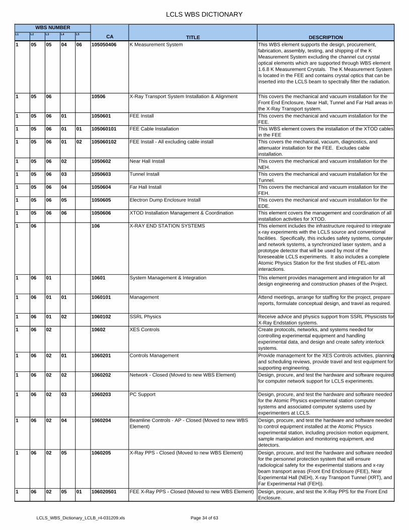
LCLS WBS DICTIONARY
L1 L2 L3 L4 L5 CA
WBS NUMBER
TITLE DESCRIPTION1 05 05 04 06 105050406 K Measurement System This WBS element supports the design, procurement,
fabrication, assembly, testing, and shipping of the K Measurement System excluding the channel cut crystal optical elements which are supported through WBS element 1.6.8 K Measurement Crystals. The K Measurement System is located in the FEE and contains crystal optics that can be inserted into the LCLS beam to spectrally filter the radiation.
1 05 06 10506 X-Ray Transport System Installation & Alignment This covers the mechanical and vacuum installation for the Front End Enclosure, Near Hall, Tunnel and Far Hall areas in the X-Ray Transport system.
1 05 06 01 1050601 FEE Install This covers the mechanical and vacuum installation for the FEE.
1 05 06 01 01 105060101 FEE Cable Installation This WBS element covers the installation of the XTOD cables in the FEE
1 05 06 01 02 105060102 FEE Install - All excluding cable install This covers the mechanical, vacuum, diagnostics, and attenuator installation for the FEE. Excludes cable installation.
1 05 06 02 1050602 Near Hall Install This covers the mechanical and vacuum installation for the NEH.
1 05 06 03 1050603 Tunnel Install This covers the mechanical and vacuum installation for the Tunnel.
1 05 06 04 1050604 Far Hall Install This covers the mechanical and vacuum installation for the FEH.
1 05 06 05 1050605 Electron Dump Enclosure Install This covers the mechanical and vacuum installation for the EDE.
1 05 06 06 1050606 XTOD Installation Management & Coordination This element covers the management and coordination of all installation activities for XTOD.
1 06 106 X-RAY END STATION SYSTEMS This element includes the infrastructure required to integrate x-ray experiments with the LCLS source and conventional facilities. Specifically, this includes safety systems, computer and network systems, a synchronized laser system, and a prototype detector that will be used by most of the foreseeable LCLS experiments. It also includes a complete Atomic Physics Station for the first studies of FEL-atom interactions.
1 06 01 10601 System Management & Integration This element provides management and integration for all design engineering and construction phases of the Project.
1 06 01 01 1060101 Management Attend meetings, arrange for staffing for the project, prepare reports, formulate conceptual design, and travel as required.
1 06 01 02 1060102 SSRL Physics Receive advice and physics support from SSRL Physicists for X-Ray Endstation systems.
1 06 02 10602 XES Controls Create protocols, networks, and systems needed for controlling experimental equipment and handling experimental data, and design and create safety interlock systems.
1 06 02 01 1060201 Controls Management Provide management for the XES Controls activities, planningand scheduling reviews, provide travel and test equipment for supporting engineering.
1 06 02 02 1060202 Network - Closed (Moved to new WBS Element) Design, procure, and test the hardware and software required for computer network support for LCLS experiments.
1 06 02 03 1060203 PC Support Design, procure, and test the hardware and software needed for the Atomic Physics experimental station computer systems and associated computer systems used by experimenters at LCLS.
1 06 02 04 1060204 Beamline Controls - AP - Closed (Moved to new WBS Element)
Design, procure, and test the hardware and software needed to control equipment installed at the Atomic Physics experimental station, including precision motion equipment, sample manipulation and monitoring equipment, and detectors.
1 06 02 05 1060205 X-Ray PPS - Closed (Moved to new WBS Element) Design, procure, and test the hardware and software needed for the personnel protection system that will ensure radiological safety for the experimental stations and x-ray beam transport areas (Front End Enclosure (FEE), Near Experimental Hall (NEH), X-ray Transport Tunnel (XRT), and Far Experimental Hall (FEH)).
1 06 02 05 01 106020501 FEE X-Ray PPS - Closed (Moved to new WBS Element) Design, procure, and test the X-Ray PPS for the Front End Enclosure.
LCLS_WBS_Dictionary_LCLB_r4-031209.xls Page 34 of 63

LCLS WBS DICTIONARY
L1 L2 L3 L4 L5 CA
WBS NUMBER
TITLE DESCRIPTION1 06 02 06 1060206 X-Ray MPS - Closed (Moved to new WBS Element) Design, procure, and test the hardware and software needed
for the machine protection system that will minimize the possibility of significant damage to the LCLS source due to accidents in the experimental stations and x-ray beam transport areas (Front End Enclosure, Near Experimental Hall, X-ray Transport Tunnel, and Far Experimental Hall).
1 06 02 06 01 106020601 FEE X-Ray MPS Design, procure, and test the X-Ray MPS for the Front End Enclosure.
1 06 02 07 1060207 AMOS Experiment Controls X1 Design the hardware and software needed to control equipment installed at the High Field Atomic Physics experimental station (X1), including precision motion equipment, sample manipulation and monitoring equipment, optics, detectors, and diagnostics.
1 06 02 07 01 106020701 AMOS Requirements, Design, Setup Design the hardware and software needed to control equipment installed at the Atomic Physics experimental station X1.
1 06 02 07 07 106020707 Development Hardware & Software Procure hardware and software for test setups to develop andtest contol and DAQ components
1 06 02 07 08 106020708 Beam Viewing System for Phase 1 Design, procure, and test the beamviewing system for the initial phase of the experiment
1 06 02 07 09 106020709 Beam Viewing System for Phase 2 Design, procure, and test the beamviewing system for the later phase of the experiment
1 06 02 07 12 106020712 Differential Pumping Design, procure, and test the hardware and software for the differential pumping controls
1 06 02 07 14 106020714 Temperature Monitoring Design, procure, and test the hutch temperature monitoring system
1 06 02 07 15 106020715 Gas Storage & Delivery System Design, procure, and test the gas storage and delivery system
1 06 02 07 16 106020716 High Field Physics Chamber Design, procure, and test the controls for the experimental chamber
1 06 02 07 17 106020717 Diagnostics Chamber Design, procure, and test the controls for the diagnostics chamber
1 06 02 07 18 106020718 Total Power Measurement Design, procure, and test the controls for the total energy measurement system
1 06 02 08 1060208 AMOS Particle Imaging Controls Design the hardware and software needed to control equipment installed at the Particle Imaging Atomic Physics experimental station (X2).
1 06 02 08 01 106020801 AMOS Particle Imaging Controls Design the hardware and software needed to control equipment installed at the Atomic Physics experimental station X2.
1 06 02 08 02 106020802 AMOS Particle Imaging Software Procure, and test the software needed to control the X2 Particle Imaging instrument.
1 06 02 09 1060209 Controls Management Provide management for the XES Controls activities, planningand scheduling reviews, provide travel and test equipment for supporting engineering.
1 06 02 10 1060210 Global Controls System Create protocols, networks, and systems needed for controlling experimental equipment and handling experimental data, and design and create safety interlock systems.
1 06 02 10 01 106021001 Network Design, procure, and test the hardware and software required for computer network support for LCLS experiments.
1 06 02 10 02 106021002 Machine Protection System Design, procure, and test the hardware and software needed for the machine protection system that will minimize the possibility of significant damage to the LCLS source due to accidents in the experimental stations and x-ray beam transport areas (front end enclosure, Near Experimental Hall, x-ray transport Tunnel, and Far Experimental Hall).
1 06 02 10 03 106021003 Personnel Protection System Design, procure, and test the hardware and software needed for the personnel protection system that will ensure radiological safety for the experimental stations and x-ray beam transport areas (front end enclosure, Near Experimental Hall, x-ray transport tunnel, and Far Experimental Hall).
1 06 02 10 04 106021004 Laser Safety System (LSS) Design, procure, and test the hardware and software needed for the personnel protection system that will ensure safe operation of the laser system for the laser laboratory, beam transport and experimental hutches in the Near Experimental Hall.
LCLS_WBS_Dictionary_LCLB_r4-031209.xls Page 35 of 63

LCLS WBS DICTIONARY
L1 L2 L3 L4 L5 CA
WBS NUMBER
TITLE DESCRIPTION1 06 02 10 05 106021005 User Safeguards Design, procure, and test the hardware and software needed
for user safeguard systems that will ensure safety of the usersin the experimental areas (FEE, NEH, Tunnel, FEH).
1 06 02 10 06 106021006 Timing System Design, procure, and test the hardware and software required for a timing system to provide timing information for the experiments through the EPICS systems.
1 06 02 10 07 106021007 Data Management Design, procure, and test the hardware and software required for data management system supporting the data storage andprocessing needs of the experiments.
1 06 02 10 08 106021008 Global Cabling & Racks Design and procure the cabling and racks need for all the global control systems.
1 06 02 10 09 106021009 Laser Timing Design, procure, and test the hardware and software required for a high precision low jitter laser based timing system as a timng backbone for the LCLS including the experimental areas.
1 06 02 10 11 106021011 Common Hutch Controls Design, procure, and test the hardware and software required for common hutch controls as 120-Hz beam-data exchange, workstations, etc
1 06 02 10 12 106021012 Data Acquisition (DAQ) Design, procure, and test the hardware and software required for the data acquisition at 120Hz from the readout devices
1 06 02 10 13 106021013 Archives Design, procure, and test the hardware and software required to archive the 120-Hz EPICS and also science data
1 06 02 10 14 106021014 Data Retrieval & Analysis Design, procure, and test the hardware and software required to retrieve and analyze EPICS and also science data
1 06 02 11 1060211 Laser Controls Design, procure, and test the hardware and software required to control the laser of the AMO experiment in the Near Hall.
1 06 02 12 01 106021201 SXR Requirements, Design & Set-up All effort to define and document the experiment requirementsfrom the controls and data systems side. Includes preparationof engineering specification documents (ESD) and interface control documents (ICD). Preparation for reviews.
1 06 02 12 02 106021202 SXR Hardware Procurement All effort to procure controls and data system components for the SXR beamline. List of components to be procured is based on ESD and ICD released documents.
1 06 02 12 03 106021203 SXR EDI Software & Hardware All effort to produce software for the hardware components for the SXR beamline. Includes debugging of the system.
1 06 04 10604 XES Laser System Design, procure, and receive the ultrafast laser system, the laser diagnostics, the laser transport of the Atomic Physics Station that will be installed in the Near Experimental Hall. Specify, design and certify the laser safety system.
1 06 04 01 1060401 XES Laser Specify, procure, and receive the XES laser system that will be installed in the Near Experimental Hall for the Atomic Physics Station.
1 06 04 02 1060402 Laser Diagnostics Design, procure, and test the hardware and software that will be used to monitor the operation of the ultrafast laser system in the Near Experimental Hall.
1 06 04 03 1060403 Laser Optical Transport Design, procure, and test the optical transport system for transporting the ultrashort laser pulses to the experimental hutche(s) in the Near Experimental Hall.
1 06 04 04 1060404 Laser Safety Specify, design, review, certify and procure the Laser safety systems for the XES laser system to ensure laser operation according to SLAC Laser Safety rules.
1 06 05 10605 X-Ray Detectors Specify, procure, and test prototype detectors that will be needed for the first experiments at LCLS. Development of advanced detector concepts that are essential to LCLS are included under 2.6 as R&D.
1 06 05 01 1060501 Beam Imaging Beam Imaging detector descoped. 1 06 05 04 1060504 Detector & Streak Camera Detector Engineering activities to manage and coordinate all
detector development programs for the Endstation Systems atLCLS including the R&D detector project in WBS 2.6.
1 06 05 04 01 106050401 X-Ray Detector Management Detector Engineering activities to manage and coordinate all detector development programs for the Endstation Systems atLCLS including the R&D detector project in WBS 2.6.
LCLS_WBS_Dictionary_LCLB_r4-031209.xls Page 36 of 63

LCLS WBS DICTIONARY
L1 L2 L3 L4 L5 CA
WBS NUMBER
TITLE DESCRIPTION1 06 06 10606 System Installation & Alignment This element provides for System Installation and Alignment
in all areas of the X-Ray Endstation system (Front End Enclosure, Near Hall, Tunnel, and Far Hall). Specifically, this includes controls, computer and network systems, safety systems, laser system, x-ray detector and instrumentation andinfrastructure for the atomic physics station. This also includes the integration of the X-Ray Endstation system with other components of the LCLS source, such as the LCLS timing and control system, vacuum system and conventional facilities. Initial test activities are included in this section.
1 06 06 01 1060601 Front End Install This element provides for System Installation and Alignment in the Front End Enclosure. Specifically, this includes controls, computer and network systems and safety systems.
1 06 06 02 1060602 Near Hall Install This element provides for System Installation and Alignment in the Near Hall. Specifically, this includes controls, computer and network systems, safety systems, a complete instrument of a Atomic Physics Station with its experimental chambers and their vacuum components, and the laser system and optical transport. Initial test activities of these systems are included in this section.
1 06 06 02 01 106060201 Near Hall Install Controls Closed.1 06 06 02 02 106060202 Near Hall Install Network Fiber This element covers the installation and cable termination of
the network fiber for the FEE and the NEH. Also included is cable plant design, installation contract, and oversight.
1 06 06 02 04 106060204 NEH Install AMO Experiment This element covers all Atomic Physics system installation in the Near Hall.
1 06 06 02 05 106060205 NEH Install Laser This element covers the installation of the laser system and the optical transport in the Near Hall.
1 06 06 02 06 106060206 NEH Install PPS This element covers all Personal Protection System installation, testing and certifying in the Near Hall.
1 06 06 02 09 106060209 NEH Install Timing This element covers the installation of the LBL timing system. It includes installation of the fiber trunk from sector 20 up to the NEH. Also included is cable plant design, installation contract, and oversight.
1 06 06 02 10 106060210 SXR Instrument Installation This element includes labor and incidental materials for installation of the SXR instrument systems in the NEH.
1 06 06 02 99 106060299 NEH Install - Other This element covers installation of components, such as, racks for controls, beamline components not integral with AMO or laser equipment.
1 06 06 03 1060603 Tunnel Install This element provides for System Installation and Alignment in the Tunnel. Specifically, this includes controls, computer and network systems, and safety systems.
1 06 06 04 1060604 Far Hall Install This element provides for System Installation and Alignment in the Far Hall. Specifically, this includes controls, computer and network systems, safety systems, and x-ray detector.
1 06 06 05 1060605 Electron Dump Enclosure Install This element provides for System Installation and Alignment in the Electron Dump Enclosure. Specifically, this includes safety systems.
1 06 06 06 1060606 XES Installation Management & Coordination This element covers the management and coordination of all installation activities for XES.
1 06 07 10607 AMOS Experiment This element covers specification, design, procurement and testing of the hardware needed for the AMO instruments including diagnostics and focussing needs. Management tasks for the technical and safety reviews are also included.
1 06 07 01 1060701 AMO Exp - Management & Design This WBS section covers the AMO management tasks of performing technical design and safety reviews, and producing documentation and plans.
1 06 07 02 1060702 AMO Exp - High Field Physics This element includes the procurement, assembly and testing of the AMO High Field Physics instrument (also labeled X1). This includes detectors, sample source, vacuum system and the differential pumping system.
1 06 07 03 1060703 AMO Exp - Refocus Optics This element includes the procurement, assembly,alignment and testing of the AMO refocussing optics.
LCLS_WBS_Dictionary_LCLB_r4-031209.xls Page 37 of 63

LCLS WBS DICTIONARY
L1 L2 L3 L4 L5 CA
WBS NUMBER
TITLE DESCRIPTION1 06 07 04 1060704 AMO Exp - Diagnostics This element includes the procurement, assembly and testing
of the AMO diagnostics.1 06 08 10608 K Measurement Crystals This element includes tasks in suppport of building the K
Measurement spectrometer. The remainder of the tasks are covered in the WBS 1.5.
1 06 08 01 1060801 K Measurement Crystals This element includes the preparation of the Physics Requirement Document for the K Measurement spectrometer and the procurement of the crystals for this instrument.
1 06 09 10609 Mechanical Systems This element covers specification, design, procurement, assembly and testing of mechanical systems which include PPS stopper hardware and PPS shielding. The safety and Radiation Physics Review process is also included.
1 06 09 01 1060901 PPS Stoppers This element covers specification, design, procurement, assembly and testing of the PPS stopper hardware.
1 06 09 02 1060902 PPS Shielding This element covers specification, design, procurement, assembly and testing of the PPS shielding.
1 06 09 03 1060903 NEH Hutch Doors This element covers specification, design, procurement, assembly and testing of 3 hutch doors for the NEH, one for each hutch. Doors are 44" wide, sliding doors with frames and lead lining.
1 06 10 10610 SXR Instrument This element includes labor and incidental materials for integration and installation of SXR systems.
1 06 10 01 1061001 SXR Instrument Management and Design This element includes labor for integration SXR systems into the LCLS and reviews of SXR systems.
1 09 109 CONVENTIONAL FACILITIES The Conventional Facilities for the Linac Coherent Light Source (LCLS) will include renovations to the existing SLAC facilities and the development of new facilities. Included will be all major systems and subsystems contained herein that will be required to support the facilities related to the LCLS programmatic requirements. The scope of the WBS will include 17 elements: Sector 20 Injector Facilities, Magnetic Measuring Facility, BTH West, Linac Upgrades, Research Yard Modifications, Beam Transport Hall, Front End Enclosure, Electron Beam Dump, Near Experimental Hall, Undulator Hall, X-Ray Transport & Diagnostics, Far Experimental Hall, BTH Service Building 2.1, 2.2, and 2.3, UHService Building 3.1, Service Yard FEH , Central Utility Plant, and SLAC Space Renovation for LCLS Ops
1 09 109 CONVENTIONAL FACILITIES (Continued) Activities within these elements include, site preparation and development (including establishment of survey monuments for site alignment), beam line housings including a beam dump, renovations to existing facilities, buildings, service buildings, utility systems (including cooling systems), fire protection systems, roads, sidewalks, berms, fencing and parking areas.
1 09 01 10901 System Management & Integration This element will provide the overall project management to implement and integrate the design, construction, checkout and close-out for all phases of the project related to conventional facilities.
1 09 01 01 1090101 Management This element will provide overall level of effort management support for conventional facilities to include development of reports and peer reviews, attendance of meetings, insure integration of other systems interfacing with conventional facilities, software acquisitions and travel as required, managing the WBS including cost, schedule and resources; coordinate Title I, Title II and Title III efforts with AE firms and in-house support staff engineers, designers and drafters; coordinate Title III with subcontractors (including architecturaland engineering firms) and general contractors and construction managers, and managing the close-out of activities including commissioning and final acceptance by end users.
LCLS_WBS_Dictionary_LCLB_r4-031209.xls Page 38 of 63

LCLS WBS DICTIONARY
L1 L2 L3 L4 L5 CA
WBS NUMBER
TITLE DESCRIPTION1 09 01 02 1090102 CAM/CF Engineering This element covers SLAC project management support
during Title I, Title II and Title III activities throughout the WBS. The UTR will provide oversight for subcontractors (including architectural and engineering firms), labor service and in-house labor. During the construction phase (Title III), SLAC Engineering / UTR has the responsibility to monitor construction activities including safety program, tests for bolt torque, welding, concrete strength, pressure certification, fire systems and electrical testing for project compliance with technical specifications and regulatory compliance. ETC baseline redefined the Title as "Engineering / CAM" to include CF engineering support and AE engineering support for Beam-Path.
1 09 01 03 1090103 Construction Management & AE Support This element will provide a support role for various construction management activities in support of the WBS. CM will support all phases of activities to include pre-construction services, bidding, field supervision, commissioning, and close-out. Particular emphasis will be given to validation of WBS schedules and estimates, value engineering and general construction support activities including Safety plan, EP site sampling analysis/characterization and disposal plans, quality control and preparing bid packages to release for construction. ETC baseline redefined the scope for this element and transferred A&E Title 3 engineering support to WBS 1.09.01.02.
1 09 01 04 1090104 Mechanical Design (MD) This element will provide SLAC MD drafting support and drawing research for as-builts in support of the WBS for Title I and Title II activities.
1 09 01 04 01 109010401 Mechanical Design Title 1 (Linac not included) This element will provide MD effort (excluding Linac) in support of Title I activities.
1 09 01 04 02 109010402 Mechanical Design T1 Linac Facilities This element will provide MD effort directly related to the Linac in support of Title I activities.
1 09 01 04 03 109010403 Mechanical Design Title 2 (Linac not included) This element will provide MD effort (excluding Linac) in support of Title II activities.
1 09 01 04 04 109010404 Mechanical Design T2 Linac Facilities This element will provide MD effort directly related to the Linac in support of Title II activities.
1 09 01 04 05 109010405 Mechanical Design Title 3 Linac Facility This element will provide MD effort directly related to the Linac in support of Title III activities.
1 09 01 04 06 109010406 Mechanical Design Title 3 (Linac not Included) This element will provide MD effort (excluding Linac) in support of Title III activities.
1 09 01 05 1090105 Conventional Experiment Facility (CEF) This element will provide SLAC CEF effort in support of the WBS for utility upgrades and misc engineering in-house support and project coordination in support of for Title I and Title II activities (Pre-Title I and Pre-Title II). Activities included in this element are field surveying, gathering user requirements, developing design criteria packages, obtaining user review and approvals, assisting in the request for proposal packages for engineering and construction firms, assisting in job walks for engineering and construction firms.
1 09 01 05 01 109010501 CEF Engineering Title 1(Linac Not Included) This element will provide SLAC CEF effort (excluding Linac) in support of Title I activities.
1 09 01 05 02 109010502 CEF Engineering Title 1 Linac Facility This element will provide SLAC CEF effort directly related to the Linac activities in support of Title I activities.
1 09 01 05 03 109010503 CEF Engineering Title 2 (Linac Not Included) This element will provide SLAC CEF effort (excluding Linac) in support of Title II activities.
1 09 01 05 04 109010504 CEF Design Linac Facility Title 2 This element will provide SLAC CEF effort directly related to the Linac activities in support of Title II activities.
1 09 02 10902 Title 1 & Title 2 Conventional Facilities This element will provide both SLAC in-house engineering, drafting support, and subcontractor architectural/engineering support for the Title I and Title II design efforts for the following WBS elements: Sector 20 Injector Facilities, Magnetic Measuring Facility, Main Control Center Modifications, Linac Upgrades, Beam Transport Hall, Research Yard Modifications, Undulator Hall, Front End Enclosure, Beam Dump, Near Experimental Hall, X-Ray Transport & Diagnostic Tunnel, Far Experimental Hall and theCentral Lab Office Complex.
LCLS_WBS_Dictionary_LCLB_r4-031209.xls Page 39 of 63

LCLS WBS DICTIONARY
L1 L2 L3 L4 L5 CA
WBS NUMBER
TITLE DESCRIPTION1 09 02 02 1090202 A & E Services (S20, MMF, MMC not Incl) This element will provide architectural and engineering
support for the WBS (excluding S20 and MMF). Included will be Title I and Title II construction document development to include drawings, specifications, studies and analyses, engineering and geotechnical study tunnel reports, cost and schedule estimates, renderings and engineering calculations.
1 09 02 02 01 109020201 Title 1 Design This element will provide the preliminary architectural and engineering support for Title I phase of the design development for conventional facilities. This design phase further develops the conceptual design to include engineering studies and analyses, risk assessments, preliminary drawings and engineering specifications, cost and schedule estimates, and life cycle cost estimates. This phase will consume up to a third of the engineering effort.
1 09 02 02 02 109020202 Title 2 Design This element will provide the architectural and engineering support for Title II phase of the design development for conventional facilities, including final working drawings, specifications and complete bidding documents for conventional facilities. This phase commences after approval of the Title I design by the DOE.
1 09 02 03 1090203 A & E Services - (S20, MMF,MCC) This element will provide architectural and engineering support for Sector 20 (shielding wall, RF hut and alcove modifications), Magnetic Measuring Facility and the Main Control Center upgrades. Included will be Title I and Title II construction document development to include drawings, specifications, studies and analyses, engineering reports, costestimates, renderings and engineering calculations.
1 09 02 03 01 109020301 Title 1 Design (Sector 20) This element will provide the preliminary architectural and engineering support for Title I phase. This design phase further develops the conceptual design to include engineering studies and analyses, risk assessments, preliminary drawings and engineering specifications, cost and schedule estimates, and life cycle cost estimates. This phase will consume up to a third of the engineering effort.
1 09 02 03 02 109020302 Title 2 Design (Sector 20) This element will provide the architectural and engineering support for Title II phase of the design development for S20 Injector Facilities, including final working drawings, specifications and complete bidding documents. This phase commences after approval of the Title I design by the DOE.
1 09 02 03 03 109020303 Title 1 Design (MMF) This element will provide the preliminary architectural and engineering support for Title I phase. This design phase further develops the conceptual design to include engineering studies and analyses, risk assessments, preliminary drawings and engineering specifications, cost and schedule estimates, and life cycle cost estimates. This phase will consume up to a third of the engineering effort.
1 09 02 03 04 109020304 Title 2 Design (MMF) This element will provide the architectural and engineering support for Title II phase of the design development for MMF, including final working drawings, specifications and complete bidding documents. This phase commences after approval ofthe Title I design by the DOE.
LCLS_WBS_Dictionary_LCLB_r4-031209.xls Page 40 of 63

LCLS WBS DICTIONARY
L1 L2 L3 L4 L5 CA
WBS NUMBER
TITLE DESCRIPTION1 09 03 10903 Construction -T3 Conventional Facilities This element will provide the construction phase of activities
to cover the receipt, inspection, assembly of the project conventional facilities, as well as any changes that are required during construction. Included will be support of: obtaining permits, safety plan, quality control, site preparations, buildings demolition, buildings construction, tunnels, shielding blocks, control rooms, preparation areas, laser rooms, experimental hutches (NEH), cooling systems, electrical systems, cable trays, ventilation systems, HVAC systems, drainage systems and utility systems. Installation of the interiors, commissioning, testing, punchlist, furnishing, final as-built drawings, operation and maintenance manuals, on-site safety and equipment training and other documentation of the facility are also prepared as part of Title III close-out activities. At the end of Title III the project is ready for activation and operation by the operations staff. [Note: cable tray within the Linac is not included].
1 09 03 01 1090301 Sector 20 Injector Facilities This element will provide the requirements for Sector 20 Injector Facilities including the removal and rebuild/relocate Alcove Pump Room; RF Hut at approximately 200 square feet; Alcove modifications to include a new Laser Room, LoadLock Room and Control Room. This existing area consists of approximately 2,000 square feet of floor space at grade level adjacent to the Klystron Gallery. The area is in need of total renovations including roofing, siding, lighting, power, utilities, hvac and other interior modifications. The Laser Room and Load Lock Room will be environmentally controlled.
1 09 03 01 01 109030101 S20 - Site Preparation/General Requirements This element will provide the General Requirements costs for: summarization of the project, work restriction, price and payment procedure, project management and coordination, construction progress and photographic documentations, submittal procedures, references, temporary facility and controls, environmental protection, product requirements, cutting and patching, site clearance & preparation, selective demolition, and HVAC commissioning requirements.
1 09 03 01 02 109030102 S20 - Site Construction This element will provide the Site Construction materials and construction costs for: building demolition, site clearing, dewatering, excavation support and protection, earthwork, utilities, soil surface erosion control, storm drainage, hot mix asphalt paving, portland concrete pavement, and pavement joint sealants
1 09 03 01 03 109030103 S20 - Concrete This element will provide the Concrete materials and installation costs for: castinplace concrete.
1 09 03 01 04 109030104 S20 - Masonry NA1 09 03 01 05 109030105 S20 - Metals This element will provide the Metals materials and
construction costs for: structural steel, steel joists, steel deck, cold-formed metal framing, metal fabrications, metal stairs, gratings, railings, and architectural joint systems.
1 09 03 01 06 109030106 S20 - Woods & Plastics This element will provide the Rough Carpentry materials and construction costs.
1 09 03 01 07 109030107 S20 - Thermal & Moisture Protection This element will provide the Thermal and Moisture materials and construction costs for: building insulation, metal wall panels, sheet metal roofing, sheet metal flashing and trim, roof expansion assemblies, roof accessories, horizontal lifeline fall protection system, fire-resistive joint systems, and joint sealants
1 09 03 01 08 109030108 S20 - Doors & Windows This element will provide the Doors and Windows materials and construction costs for: standard steel doors& frames, access doors, overhead coiling doors, metal-framed roof hatches, and door hardware.
1 09 03 01 09 109030109 S20 - Finishes This element will provide the Finishes materials and construction costs for: gypsum board assemblies, gypsum board shaft-wall assemblies, acoustical panel ceilings, resilient floor tile, static-control resilient floor covering, exteriorpainting, interior painting, concrete floor stain, and heigh-performance coatings.
LCLS_WBS_Dictionary_LCLB_r4-031209.xls Page 41 of 63
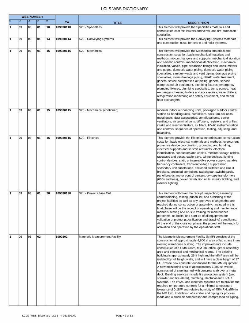
LCLS WBS DICTIONARY
L1 L2 L3 L4 L5 CA
WBS NUMBER
TITLE DESCRIPTION1 09 03 01 10 109030110 S20 - Specialties This element will provide the Specialties materials and
construction cost for: louvers and vents, and fire-protection specialties
1 09 03 01 14 109030114 S20 - Conveying Systems This element will provide the Conveying Systems materials and construction costs for: crane and hoist systems.
1 09 03 01 15 109030115 S20 - Mechanical This element will provide the Mechanical materials and construction costs for: basic mechanical materials and methods, motors, hangers and supports, mechanical vibrationand seismic controls, mechanical identification, mechanical insulation, valves, pipe expansion fittings and loops, meters and gages, domestic water piping, domestic water piping specialties, sanitary waste and vent piping, drainage piping specialties, storm drainage piping, HVAC water treatment, general-sevice compressed-air piping, general-service compressed-air equipment, plumbing fixtures, emergency plumbing fixtures, plumbing specialties, sump pumps, heat exchangers, heating boilers and accessories, water chillers, refrigeration monitoring and safety equipment, and steam heat exchangers,
1 09 03 01 15 109030115 S20 - Mechanical (continued) modular indoor air-handling units, packaged outdoor central station air handling units, humidifiers, coils, fan-coil units, metal ducts, duct accessories, centrifugal fans, power ventilators, air terminal units, diffusers, registers, and grilles, intake and relief ventilators, air filters, HVAC instrumentation and controls, sequence of operation, testing, adjusting, and balancing.
1 09 03 01 16 109030116 S20 - Electrical This element provide the Electrical materials and construction costs for: basic electrical materials and methods, overcurrent protective device coordination, grounding and bonding, electrical supports and seismic restraints, electrical identification, conductors and cables, medium-voltage cables, raceways and boxes, cable trays, wiring devices, lighting control devices, static uninterruptible power supply, variable frequency controllers, transient voltage suppression, secondary unit substations, enclosed switches and circuit breakers, enclosed controllers, switchgear, switchboards, panel boards, motor control centers, dry-type transformers (600v and less), power distribution units, interior lighting, and exterior lighting.
1 09 03 01 20 109030120 S20 - Project Close Out This element will cover the receipt, inspection, assembly, commissioning, testing, punch list, and furnishing of the project facilities as well as any approved changes that are required during construction or assembly. Included in this final phase will be the receipt of operating and maintenance manuals, testing and on-site training for maintenance personnel, as-builts, and start-up of all equipment for validation of project (specification and drawing) compliance. At the end of the close out phase, the project will be ready for activation and operation by the operations staff.
1 09 03 02 1090302 Magnetic Measurement Facility The Magnetic Measurement Facility (MMF) consists of the construction of approximately 4,800 sf area of lab space in an existing warehouse building. The improvements include construction of a CMM room, MM lab, office, girder assembly area and electrical and mechanical rooms. The existing building is approximately 25 ft high and the MMF area will be isolated by full height walls, and will have a clear height of 17 Ft. Provide new concrete foundations for the MM equipment. A new mezzanine area of approximately 1,300 sf, will be constructed of steel framed with concrete slab over a metal deck. Building services include fire protection system (wet sprinkler and fire alarm), plumbing, electrical and HVAC systems. The HVAC and electrical systems are to provide the required temperature controls for a minimal temperature tolerance of 0.18ºF and relative humidity of 45% RH, ±5% in the MM Lab. Installation of a chiller and piping for process loads and a small air compressor and compressed air piping.
LCLS_WBS_Dictionary_LCLB_r4-031209.xls Page 42 of 63

LCLS WBS DICTIONARY
L1 L2 L3 L4 L5 CA
WBS NUMBER
TITLE DESCRIPTION1 09 03 02 1090302 Magnetic Measurement Facility (continued) To accommodate the new facility some modifications will be
necessary. These changes include installation of a new electrical feeder (800 amps, 480 volts, 3 phase) and Motor Control Center for the building. Some additional modifications will include the relocation of existing racks, Haz Material Storage and office cubicles that support the Stores operation currently in place.
1 09 03 02 01 109030201 MMF - Site Preparation/General Requirements This element will provide the General Requirements costs for: mobilization, safety, project management and coordination, construction progress and photographic documentations, submittal procedures, temporary facility and environmental protection, product requirements, cutting and patching, site clearance & preparation, selective demolition, and HVAC commissioning requirements.
1 09 03 02 02 109030202 MMF - Site Construction This element will provide the Sitework materials and construction costs for: building demolition, site clearing, dewatering, excavation support and protection, earthwork, utilities, storm drainage, hot mix asphalt paving, portland concrete pavement, pavement joint sealants.
1 09 03 02 03 109030203 MMF - Concrete This element will provide the Concrete materials and installation costs for: castinplace concrete.
1 09 03 02 05 109030205 MMF - Metals This element will provide the Metals materials and construction costs for: structural steel, steel joists, steel deck, cold-formed metal framing, metal fabrications, metal stairs, gratings, railings, and architectural joint systems.
1 09 03 02 06 109030206 MMF - Woods & Plastics This element will provide the Rough Carpentry materials and construction costs.
1 09 03 02 07 109030207 MMF - Thermal & Moisture Protection This element will provide the Thermal and Moisture materials and construction costs for: electrometric sheet waterproofing, building insulation, metal wall panels, thermoplastic membrane roofing, sheet metal roofing, sheet metal flashing and trim, roof expansion assemblies, roof accessories, and joint sealants
1 09 03 02 08 109030208 MMF - Doors & Windows This element will provide the Doors and Windows materials and construction costs for: standard steel doors& frames, flush wood doors, access doors, overhead coiling doors, and door hardware.
1 09 03 02 09 109030209 MMF - Finishes This element will provide the Finishes materials and construction costs for: gypsum board assemblies, gypsum board shaft-wall assemblies, acoustical panel ceilings, exterior painting, interior painting, concrete floor sealer/epoxy.
1 09 03 02 10 109030210 MMF - Specialities This element will provide the Specialties materials and construction cost for: louvers and vents, and fire-protection specialties
1 09 03 02 13 109030213 MMF - Special Construction This element of the WBS is reserved for any special construction for the magnetic measurement facility (MMF). This would be construction not already reserved in other partsof the MMF WBS (i.e. Site Prep, Concrete, Metals, Mechanical, Electrical, etc).
1 09 03 02 14 109030214 MMF - Conveying Systems This element will provide the Conveying Systems materials and construction costs for: crane and hoist systems.
1 09 03 02 15 109030215 MMF - Mechanical This element will provide the Mechanical materials and construction costs for: basic mechanical materials and methods, motors, hangers and supports, mechanical viration and seismic controls, mechanical identification, mechanical insulation, valves, pipe expansion fittings and loops, meters and gages, domestic water piping, domestic water piping specialties, sanitary waste and vent piping, drainage piping specialties, storm drainage piping, hydronic piping, hydronic pumps , HVAC water treatment, fuel gas piping, general-sevice compressed-air piping, general-service compressed-air equipment, plumbing fixtures, emergency plumbing fixtures, plumbing specialties, sewage pumps, sump pumps, heat exchangers, heating boilers and accessories, scroll water chillers, hydronic, and heat exchanger.
LCLS_WBS_Dictionary_LCLB_r4-031209.xls Page 43 of 63

LCLS WBS DICTIONARY
L1 L2 L3 L4 L5 CA
WBS NUMBER
TITLE DESCRIPTION1 09 03 02 15 109030215 MMF - Mechanical (continued) modular indoor air-handling units, humidifiers, coils, propeller
unit heaters, metal ducts, duct accessories, centrifugal fans, air terminal units, diffusers, registers, and grilles, intake and relief ventilators, air filters, HVAC instrumentation and controls, sequence of operation, testing, adjusting, and balancing.
1 09 03 02 16 109030216 MMF - Electrical This element provide the Electrical materials and construction costs for: basic electrical materials and methods, over current protective device coordination, grounding and bonding, electrical supports and seismic restraints, electrical identification, conductors and cables, medium-voltage cables, raceways and boxes, cable trays, wiring devices, lighting control devices, variable frequency controllers, circuit breakers, enclosed controllers, panel boards, motor control centers, dry-type transformers (600v and less), power distribution units, interior lighting, and exterior lighting.
1 09 03 02 20 109030220 MMF - Project Close Out This element will cover the receipt, inspection, assembly, commissioning, testing, punch list, and furnishing of the project facilities and hardware, as well as any approved changes that are required during construction or assembly. Included in this final phase will be the receipt of operating andmaintenance manuals, testing and on-site training for maintenance personnel, as-builts, and start-up of all equipment for validation of project (specification and drawing) compliance and commissioning report. At the end of the close out phase, the project will be ready for activation and operation by the operations staff.
1 09 03 03 1090303 BTH West The Beam Transport Hall West commences from the end of the Muon Shield (~159.246 m) to the beginning of the BTH.
1 09 03 03 01 109030301 BTH West - Site Preparation This element includes the demolition and removal of existing cables and cable trays, piping, electrical conduits and wiring to allow the modification and installation of new electrical and mechanical systems and beam components.
1 09 03 03 15 109030315 BTH West Mechanical This element will provide the mechanical materials and construction costs for: fire protection and Low Conductivity piping, ventilation and balancing/testing of water systems. Plumbing includes a compressed air header and isolation valve and drainage piping system.
1 09 03 03 16 109030316 BTH West - Electrical This element will provide the installation of the project primary electrical distribution systems to the main panel source of the area. The distribution of electric power will follow downstreamand will include secondary electrical panels, transformers, disconnects, panel boards, electrical system grounding for 480V, 3 phase; 208/120V, 3 phase; and 120V single phase and cable trays. This element will include the installation and modification of general lighting, welding outlets, GFCI outlets and duplex outlets for 120V electric power.
1 09 03 03 20 109030320 BTH West Project Close Out This element will cover the receipt, inspection, commissioning, testing, punchlist, and furnishing of the project facilities and equipment, as well as any approved changes that are required during construction. Included in this final phase will be the receipt of operating and maintenance manuals, testing and on-site training for maintenance personnel, as-builts, and start-up of all equipment for validation of project (specification and drawing) compliance. At the end of the close out phase, the project willbe ready for activation and operation by the operations staff.
LCLS_WBS_Dictionary_LCLB_r4-031209.xls Page 44 of 63
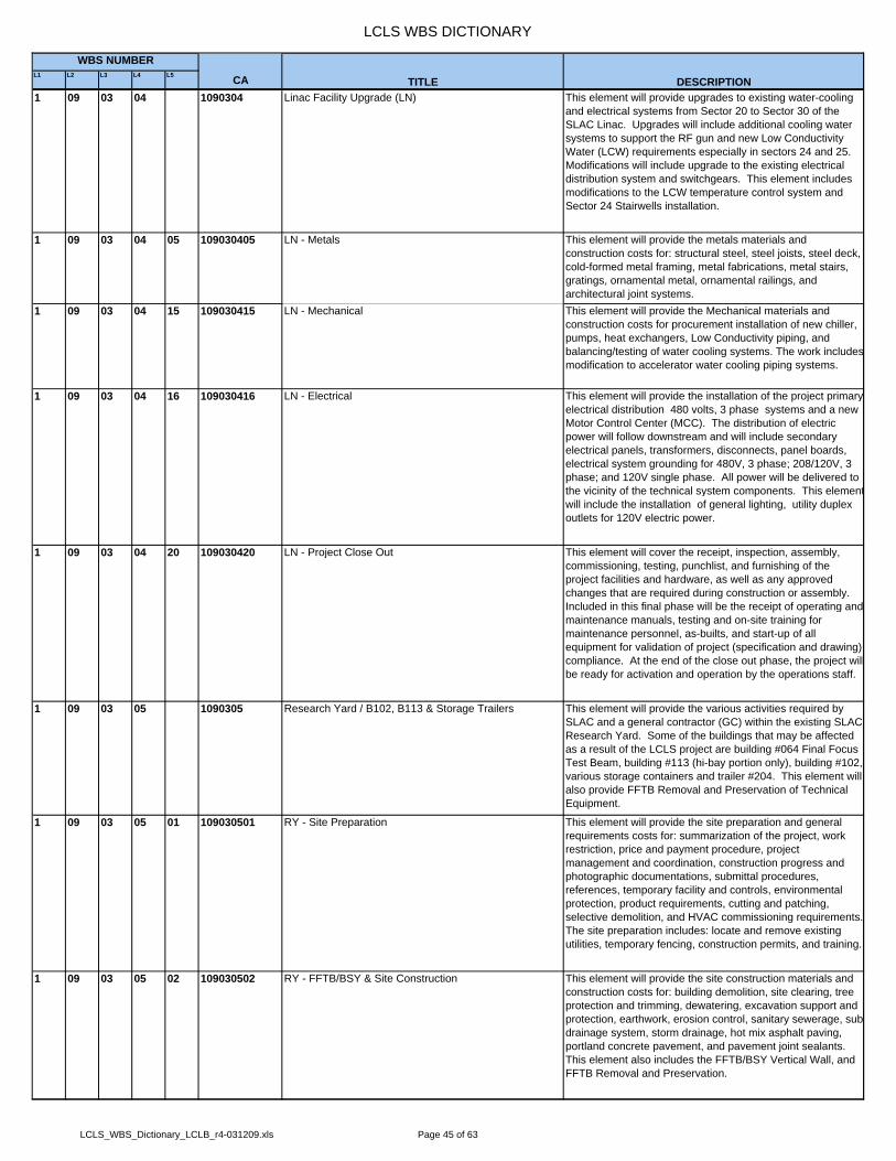
LCLS WBS DICTIONARY
L1 L2 L3 L4 L5 CA
WBS NUMBER
TITLE DESCRIPTION1 09 03 04 1090304 Linac Facility Upgrade (LN) This element will provide upgrades to existing water-cooling
and electrical systems from Sector 20 to Sector 30 of the SLAC Linac. Upgrades will include additional cooling water systems to support the RF gun and new Low Conductivity Water (LCW) requirements especially in sectors 24 and 25. Modifications will include upgrade to the existing electrical distribution system and switchgears. This element includes modifications to the LCW temperature control system and Sector 24 Stairwells installation.
1 09 03 04 05 109030405 LN - Metals This element will provide the metals materials and construction costs for: structural steel, steel joists, steel deck, cold-formed metal framing, metal fabrications, metal stairs, gratings, ornamental metal, ornamental railings, and architectural joint systems.
1 09 03 04 15 109030415 LN - Mechanical This element will provide the Mechanical materials and construction costs for procurement installation of new chiller, pumps, heat exchangers, Low Conductivity piping, and balancing/testing of water cooling systems. The work includesmodification to accelerator water cooling piping systems.
1 09 03 04 16 109030416 LN - Electrical This element will provide the installation of the project primary electrical distribution 480 volts, 3 phase systems and a new Motor Control Center (MCC). The distribution of electric power will follow downstream and will include secondary electrical panels, transformers, disconnects, panel boards, electrical system grounding for 480V, 3 phase; 208/120V, 3 phase; and 120V single phase. All power will be delivered to the vicinity of the technical system components. This elementwill include the installation of general lighting, utility duplex outlets for 120V electric power.
1 09 03 04 20 109030420 LN - Project Close Out This element will cover the receipt, inspection, assembly, commissioning, testing, punchlist, and furnishing of the project facilities and hardware, as well as any approved changes that are required during construction or assembly. Included in this final phase will be the receipt of operating andmaintenance manuals, testing and on-site training for maintenance personnel, as-builts, and start-up of all equipment for validation of project (specification and drawing) compliance. At the end of the close out phase, the project willbe ready for activation and operation by the operations staff.
1 09 03 05 1090305 Research Yard / B102, B113 & Storage Trailers This element will provide the various activities required by SLAC and a general contractor (GC) within the existing SLAC Research Yard. Some of the buildings that may be affected as a result of the LCLS project are building #064 Final Focus Test Beam, building #113 (hi-bay portion only), building #102, various storage containers and trailer #204. This element will also provide FFTB Removal and Preservation of Technical Equipment.
1 09 03 05 01 109030501 RY - Site Preparation This element will provide the site preparation and general requirements costs for: summarization of the project, work restriction, price and payment procedure, project management and coordination, construction progress and photographic documentations, submittal procedures, references, temporary facility and controls, environmental protection, product requirements, cutting and patching, selective demolition, and HVAC commissioning requirements. The site preparation includes: locate and remove existing utilities, temporary fencing, construction permits, and training.
1 09 03 05 02 109030502 RY - FFTB/BSY & Site Construction This element will provide the site construction materials and construction costs for: building demolition, site clearing, tree protection and trimming, dewatering, excavation support and protection, earthwork, erosion control, sanitary sewerage, sub drainage system, storm drainage, hot mix asphalt paving, portland concrete pavement, and pavement joint sealants. This element also includes the FFTB/BSY Vertical Wall, and FFTB Removal and Preservation.
LCLS_WBS_Dictionary_LCLB_r4-031209.xls Page 45 of 63

LCLS WBS DICTIONARY
L1 L2 L3 L4 L5 CA
WBS NUMBER
TITLE DESCRIPTION1 09 03 05 20 109030520 RY - Project Close Out This element will cover the receipt, inspection, assembly,
commissioning, testing, punchlist, and furnishing of the project facilities and hardware, as well as any approved changes that are required during construction or assembly. Included in this final phase will be the receipt of operating andmaintenance manuals, testing and on-site training for maintenance personnel, as-builts, and start-up of all equipment for validation of project (specification and drawing) compliance. At the end of the close out phase, the project willbe ready for activation and operation by the operations staff.
1 09 03 06 1090306 Pre-Purchase Equipment for Beam Path The element will provide the mechanical and electrical equipments for Beam Path construction and installation.
1 09 03 06 01 109030601 PPE - General Requirements This element will provide costs for Pre-Construction /Bid/Award , submittal release approvals, manufacture releases, equipment deliveries, and final turnover.
1 09 03 06 11 109030611 PPE - Pre-Purchase Equipment This element will provide the cost for mechanical and electrical equipments.
1 09 03 07 1090307 SITEWORK, Earthwork, Site Utilities, & Survey This element will provide construction and installation of underground utilities. This includes electrical, water, sewer and storm drain. Construction of major surface excavations. Installation of survey control and layout of items during construction and installation.
1 09 03 07 01 109030701 SW - General Requirements This element will cover CCIP insurance, bond, and mobilization to site for Earthwork, Site Utilities, SWPPP installation and maintenance, and Site Survey contractors
1 09 03 07 02 109030702 SW - Earthwork, Site Utilities & Survey This element will provide the costs for: construction and installation of underground utilities. This includes electrical, water, sewer and storm drain. Construction of major surface excavations, hot mix asphalt paving, portland concrete pavements, pavement joint sealants, and shotcrete. Installation of survey control and layout of items during construction and installation.
1 09 03 07 16 109030716 SW - Electrical This element will provide costs for construction and installation of the Power & Tel-Data underground, temporary power, feeder wire, under slab, and site lighting.
1 09 03 08 1090308 Beam Transport Hall (BTH) The new Beam Transport Hall commences from the end of the Linac to the beginning of the Undulator Hall and replaces the existing Final Focus Test Beam enclosure. The existing Linac finish floor is approximately one foot lower than the required elevation of the new facility which will be at 247.25’. The BTH will have roughly the same general footprint of the FFTB extending from the BSY wall in the direction of the beam at 227 meters (length) x 4.5 meters (width) x 3 meters (height). This element also includes the installation cost for a new BTH Switchboard which will provide power to the entire BTH area including the service buildings.
1 09 03 08 01 109030801 BTH - Site Preparation/General Requirements This element will cover CCIP insurance, bond, and mobilization to site.
1 09 03 08 03 109030803 BTH - Concrete This element will provide the Concrete materials and installation costs for: castinplace concrete.
1 09 03 08 05 109030805 BTH - Metals This element will provide the Metals materials and construction costs for: structural steel, steel joists, steel deck, cold-formed metal framing, metal fabrications, metal stairs, gratings, railings, and architectural joint systems.
1 09 03 08 15 109030815 BTH - Mechanical This element will provide the Mechanical materials and construction costs for: air handlers, fans, ductwork, chilled and hot water piping, balancing/testing and temperature controls. Plumbing includes a compressed air header, a pumped waste system.
1 09 03 08 16 109030816 BTH - Electrical This element provide the Electrical materials and construction costs for: basic power distribution from bldg 406/407 to an MCC in each Service building. The communication cable tray runs the length of the tunnel to each service building from a SLAC provided backbone conductor. This element also includes the installation costs for anew 1600 amp, 480 volts, 3phase, BTH Switchboard which will provide power to the BTH area.
LCLS_WBS_Dictionary_LCLB_r4-031209.xls Page 46 of 63
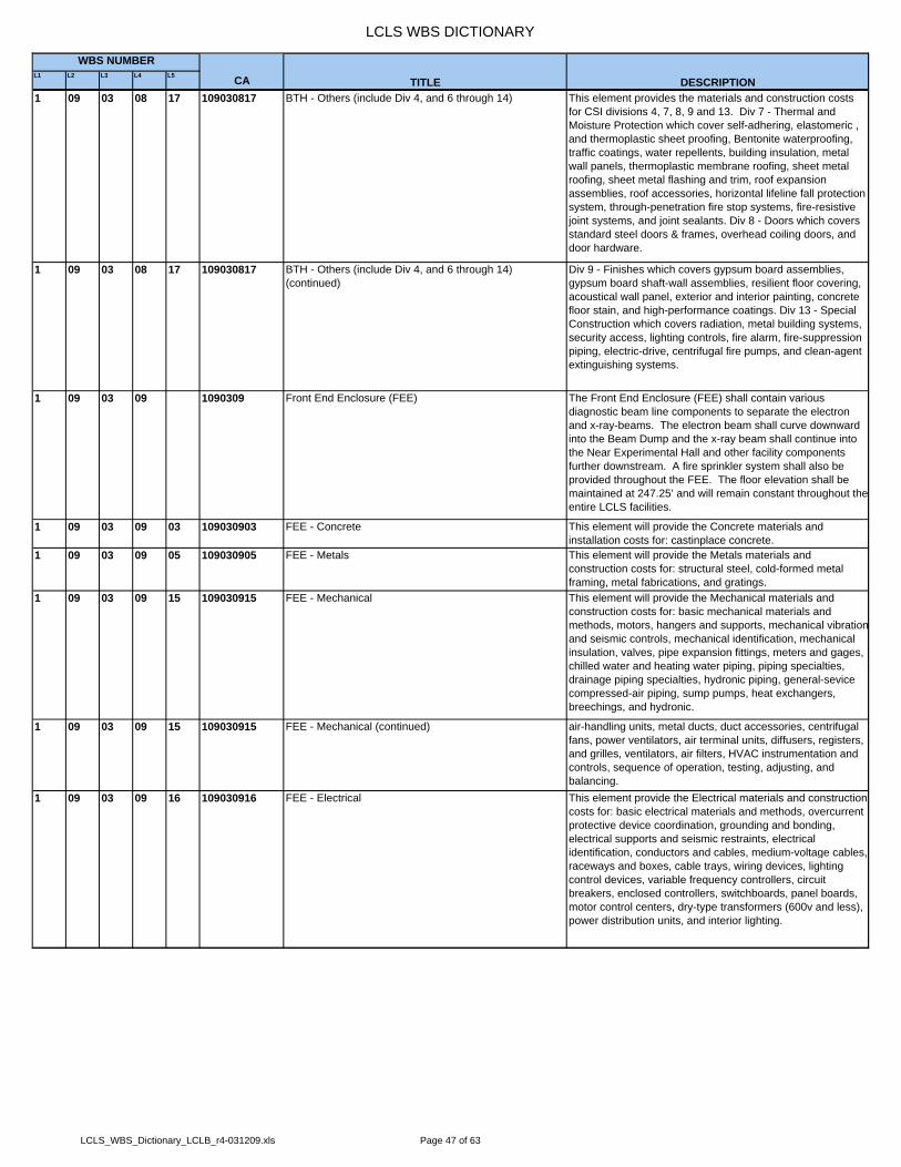
LCLS WBS DICTIONARY
L1 L2 L3 L4 L5 CA
WBS NUMBER
TITLE DESCRIPTION1 09 03 08 17 109030817 BTH - Others (include Div 4, and 6 through 14) This element provides the materials and construction costs
for CSI divisions 4, 7, 8, 9 and 13. Div 7 - Thermal and Moisture Protection which cover self-adhering, elastomeric , and thermoplastic sheet proofing, Bentonite waterproofing, traffic coatings, water repellents, building insulation, metal wall panels, thermoplastic membrane roofing, sheet metal roofing, sheet metal flashing and trim, roof expansion assemblies, roof accessories, horizontal lifeline fall protection system, through-penetration fire stop systems, fire-resistive joint systems, and joint sealants. Div 8 - Doors which covers standard steel doors & frames, overhead coiling doors, and door hardware.
1 09 03 08 17 109030817 BTH - Others (include Div 4, and 6 through 14) (continued)
Div 9 - Finishes which covers gypsum board assemblies, gypsum board shaft-wall assemblies, resilient floor covering, acoustical wall panel, exterior and interior painting, concrete floor stain, and high-performance coatings. Div 13 - Special Construction which covers radiation, metal building systems, security access, lighting controls, fire alarm, fire-suppression piping, electric-drive, centrifugal fire pumps, and clean-agent extinguishing systems.
1 09 03 09 1090309 Front End Enclosure (FEE) The Front End Enclosure (FEE) shall contain various diagnostic beam line components to separate the electron and x-ray-beams. The electron beam shall curve downward into the Beam Dump and the x-ray beam shall continue into the Near Experimental Hall and other facility components further downstream. A fire sprinkler system shall also be provided throughout the FEE. The floor elevation shall be maintained at 247.25’ and will remain constant throughout the entire LCLS facilities.
1 09 03 09 03 109030903 FEE - Concrete This element will provide the Concrete materials and installation costs for: castinplace concrete.
1 09 03 09 05 109030905 FEE - Metals This element will provide the Metals materials and construction costs for: structural steel, cold-formed metal framing, metal fabrications, and gratings.
1 09 03 09 15 109030915 FEE - Mechanical This element will provide the Mechanical materials and construction costs for: basic mechanical materials and methods, motors, hangers and supports, mechanical vibrationand seismic controls, mechanical identification, mechanical insulation, valves, pipe expansion fittings, meters and gages, chilled water and heating water piping, piping specialties, drainage piping specialties, hydronic piping, general-sevice compressed-air piping, sump pumps, heat exchangers, breechings, and hydronic.
1 09 03 09 15 109030915 FEE - Mechanical (continued) air-handling units, metal ducts, duct accessories, centrifugal fans, power ventilators, air terminal units, diffusers, registers, and grilles, ventilators, air filters, HVAC instrumentation and controls, sequence of operation, testing, adjusting, and balancing.
1 09 03 09 16 109030916 FEE - Electrical This element provide the Electrical materials and construction costs for: basic electrical materials and methods, overcurrent protective device coordination, grounding and bonding, electrical supports and seismic restraints, electrical identification, conductors and cables, medium-voltage cables, raceways and boxes, cable trays, wiring devices, lighting control devices, variable frequency controllers, circuit breakers, enclosed controllers, switchboards, panel boards, motor control centers, dry-type transformers (600v and less), power distribution units, and interior lighting.
LCLS_WBS_Dictionary_LCLB_r4-031209.xls Page 47 of 63

LCLS WBS DICTIONARY
L1 L2 L3 L4 L5 CA
WBS NUMBER
TITLE DESCRIPTION1 09 03 09 17 109030917 FEE - Others (include Div 4, and 6 through 14) This element provides the materials and construction costs
for CSI divisions 4, 7, 8, 9 and 13. Div 7 - Thermal and Moisture Protection which cover self-adhering, elastomeric , and thermoplastic sheet proofing, Bentonite waterproofing, traffic coatings, water repellents, building insulation, metal wall panels, thermoplastic membrane roofing, sheet metal roofing, sheet metal flashing and trim, roof expansion assemblies, roof accessories, horizontal lifeline fall protection system, sprayed fire-resistive materials, through-penetration fire stop systems, fire-resistive joint systems, and joint sealants. Div 8 - Doors which covers standard steel doors & frames, flush wood doors, overhead coiling doors, and door hardware.
1 09 03 09 17 109030917 FEE - Others (include Div 4, and 6 through 14) (continued)
Div 9 - Finishes which covers gypsum board assemblies, gypsum board shaft-wall assemblies, resilient floor covering, acoustical wall panel, exterior and interior painting, concrete floor stain, and high-performance coatings. Div 13 - Special Construction which covers radiation, metal building systems, security access, lighting controls, fire alarm, fire-suppression piping, electric-drive, centrifugal fire pumps, and clean-agent extinguishing systems.
1 09 03 10 1090310 Electron Beam Dump (EBD) This facility is a 132' long underground concrete cast in-place facility used to separate the electron and x-ray beams.
1 09 03 10 01 109031001 EBD - Site Preparation/General Requirements This element will provide the site preparation including steel modification, steel blocks storing, fabrication and installation of EBD Steel Shielding.
1 09 03 10 02 109031002 EBD - Site Construction This element will provide the cost for construction of electron beam dump
1 09 03 10 03 109031003 EBD - Concrete This element will provide the Concrete materials and installation costs for: castinplace concrete.
1 09 03 10 05 109031005 EBD - Metals This element will provide the Metals materials and construction costs for: structural steel, cold-formed metal framing, metal fabrications, and gratings.
1 09 03 10 15 109031015 EBD - Mechanical This element will provide the Mechanical materials and construction costs for: basic mechanical materials and methods, motors, hangers and supports, mechanical vibrationand seismic controls, mechanical identification, mechanical insulation, valves, pipe expansion fittings, meters and gages, chilled water and heating water piping, piping specialties, drainage piping specialties, hydronic piping, general-sevice compressed-air piping, sump pumps, heat exchangers, breechings, and hydronic.
1 09 03 10 15 109031015 EBD - Mechanical (continued) air-handling units, metal ducts, duct accessories, centrifugal fans, power ventilators, air terminal units, diffusers, registers, and grilles, ventilators, air filters, HVAC instrumentation and controls, sequence of operation, testing, adjusting, and balancing.
1 09 03 10 16 109031016 EBD - Electrical This element provide the Electrical materials and construction costs for: basic electrical materials and methods, overcurrent protective device coordination, grounding and bonding, electrical supports and seismic restraints, electrical identification, conductors and cables, medium-voltage cables, raceways and boxes, cable trays, wiring devices, lighting control devices, variable frequency controllers, circuit breakers, enclosed controllers, switchboards, panel boards, motor control centers, dry-type transformers (600v and less), power distribution units, interior lighting, and exterior lighting.
LCLS_WBS_Dictionary_LCLB_r4-031209.xls Page 48 of 63

LCLS WBS DICTIONARY
L1 L2 L3 L4 L5 CA
WBS NUMBER
TITLE DESCRIPTION1 09 03 10 17 109031017 EBD - Others (include Div 4, and 6 through 14) This element provides the materials and construction costs
for CSI divisions 4, 7, 8, 9 and 13. Div 7 - Thermal and Moisture Protection which cover self-adhering, elastomeric , and thermoplastic sheet proofing, Bentonite waterproofing, traffic coatings, water repellents, building insulation, metal wall panels, thermoplastic membrane roofing, sheet metal roofing, sheet metal flashing and trim, roof expansion assemblies, roof accessories, horizontal lifeline fall protection system, sprayed fire-resistive materials, through-penetration fire stop systems, fire-resistive joint systems, and joint sealants. Div 8 - Doors which covers standard steel doors & frames, flush wood doors, overhead coiling doors, and door hardware.
1 09 03 10 17 109031017 EBD - Others (include Div 4, and 6 through 14) (continued)
Div 9 - Finishes which covers gypsum board assemblies, gypsum board shaft-wall assemblies, resilient floor covering, acoustical wall panel, exterior and interior painting, concrete floor stain, and high-performance coatings. Div 13 - Special Construction which covers radiation, lighting controls, fire alarm, fire-suppression piping, electric-drive, centrifugal fire pumps, and clean-agent extinguishing systems.
1 09 03 11 1090311 Near Experimental Hall (NEH) The Near Experimental Hall (NEH) is a two-story structure (below grade) that will begin downstream of the FEE and will extend approximately 33 meters in the direction of the beam. The primary function of the NEH is to house three experimental hutches. Each hutch shall have its independent PPS entry (provided by others). Adjacent to the hutches shall be floor space to accommodate Prep and Control areas. Provisions shall be made for restroom facilities and 5-ton freight elevator. The second floor shall house a Laser Bay The NEH shall be provided with heating, cooling, ventilation and smoke purge systems. Provisions shall be made for the hutches to have process exhaust fans. A fire sprinkler system shall also be provided throughout the NEH. The floor elevation shall be maintained at 247.25’ and remain constant throughout the entire LCLS facilities.
1 09 03 11 01 109031101 NEH - Site Preparation/General Requirements This element will provide CCIP insurance, bond, and mobilization to site.
1 09 03 11 02 109031102 NEH - Site Construction This element will provide the installation costs for Fire Protection (Hazard Analysis).
1 09 03 11 03 109031103 NEH - Concrete This element will provide the Concrete materials and installation costs for: castinplace concrete.
1 09 03 11 05 109031105 NEH - Metals This element will provide the Metals materials and construction costs for: structural steel, cold-formed metal framing, metal fabrications, and gratings.
1 09 03 11 15 109031115 NEH - Mechanical This element will provide the Mechanical materials and construction costs for: basic mechanical materials and methods, motors, hangers and supports, mechanical vibrationand seismic controls, mechanical identification, mechanical insulation, valves, pipe expansion fittings, meters and gages, chilled water and heating water piping, piping specialties, drainage piping specialties, hydronic piping, general-sevice compressed-air piping, sump pumps, heat exchangers, breechings, and hydronic.
1 09 03 11 15 109031115 NEH - Mechanical (continued) air-handling units, metal ducts, duct accessories, centrifugal fans, power ventilators, air terminal units, diffusers, registers, and grilles, ventilators, air filters, HVAC instrumentation and controls, sequence of operation, testing, adjusting, and balancing.
1 09 03 11 16 109031116 NEH - Electrical This element provide the Electrical materials and construction costs for: basic electrical materials and methods, overcurrent protective device coordination, grounding and bonding, electrical supports and seismic restraints, electrical identification, conductors and cables, medium-voltage cables, raceways and boxes, cable trays, wiring devices, lighting control devices, variable frequency controllers, circuit breakers, enclosed controllers, switchboards, panel boards, motor control centers, dry-type transformers (600v and less), power distribution units, interior lighting, and exterior lighting.
LCLS_WBS_Dictionary_LCLB_r4-031209.xls Page 49 of 63
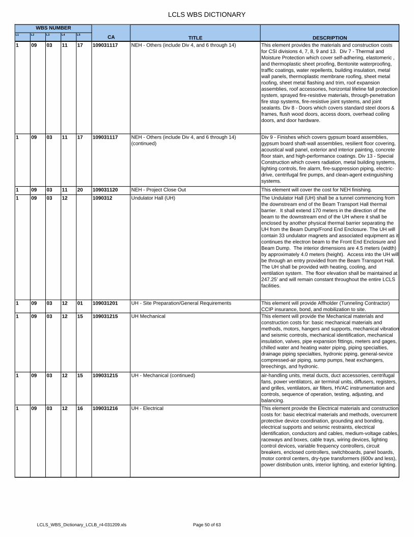
LCLS WBS DICTIONARY
L1 L2 L3 L4 L5 CA
WBS NUMBER
TITLE DESCRIPTION1 09 03 11 17 109031117 NEH - Others (include Div 4, and 6 through 14) This element provides the materials and construction costs
for CSI divisions 4, 7, 8, 9 and 13. Div 7 - Thermal and Moisture Protection which cover self-adhering, elastomeric , and thermoplastic sheet proofing, Bentonite waterproofing, traffic coatings, water repellents, building insulation, metal wall panels, thermoplastic membrane roofing, sheet metal roofing, sheet metal flashing and trim, roof expansion assemblies, roof accessories, horizontal lifeline fall protection system, sprayed fire-resistive materials, through-penetration fire stop systems, fire-resistive joint systems, and joint sealants. Div 8 - Doors which covers standard steel doors & frames, flush wood doors, access doors, overhead coiling doors, and door hardware.
1 09 03 11 17 109031117 NEH - Others (include Div 4, and 6 through 14) (continued)
Div 9 - Finishes which covers gypsum board assemblies, gypsum board shaft-wall assemblies, resilient floor covering, acoustical wall panel, exterior and interior painting, concrete floor stain, and high-performance coatings. Div 13 - Special Construction which covers radiation, metal building systems, lighting controls, fire alarm, fire-suppression piping, electric-drive, centrifugal fire pumps, and clean-agent extinguishing systems.
1 09 03 11 20 109031120 NEH - Project Close Out This element will cover the cost for NEH finishing.1 09 03 12 1090312 Undulator Hall (UH) The Undulator Hall (UH) shall be a tunnel commencing from
the downstream end of the Beam Transport Hall thermal barrier. It shall extend 170 meters in the direction of the beam to the downstream end of the UH where it shall be enclosed by another physical thermal barrier separating the UH from the Beam Dump/Frond End Enclosure. The UH will contain 33 undulator magnets and associated equipment as it continues the electron beam to the Front End Enclosure and Beam Dump. The interior dimensions are 4.5 meters (width) by approximately 4.0 meters (height). Access into the UH will be through an entry provided from the Beam Transport Hall. The UH shall be provided with heating, cooling, and ventilation system. The floor elevation shall be maintained at 247.25’ and will remain constant throughout the entire LCLS facilities.
1 09 03 12 01 109031201 UH - Site Preparation/General Requirements This element will provide Affholder (Tunneling Contractor) CCIP insurance, bond, and mobilization to site.
1 09 03 12 15 109031215 UH Mechanical This element will provide the Mechanical materials and construction costs for: basic mechanical materials and methods, motors, hangers and supports, mechanical vibrationand seismic controls, mechanical identification, mechanical insulation, valves, pipe expansion fittings, meters and gages, chilled water and heating water piping, piping specialties, drainage piping specialties, hydronic piping, general-sevice compressed-air piping, sump pumps, heat exchangers, breechings, and hydronic.
1 09 03 12 15 109031215 UH - Mechanical (continued) air-handling units, metal ducts, duct accessories, centrifugal fans, power ventilators, air terminal units, diffusers, registers, and grilles, ventilators, air filters, HVAC instrumentation and controls, sequence of operation, testing, adjusting, and balancing.
1 09 03 12 16 109031216 UH - Electrical This element provide the Electrical materials and construction costs for: basic electrical materials and methods, overcurrent protective device coordination, grounding and bonding, electrical supports and seismic restraints, electrical identification, conductors and cables, medium-voltage cables, raceways and boxes, cable trays, wiring devices, lighting control devices, variable frequency controllers, circuit breakers, enclosed controllers, switchboards, panel boards, motor control centers, dry-type transformers (600v and less), power distribution units, interior lighting, and exterior lighting.
LCLS_WBS_Dictionary_LCLB_r4-031209.xls Page 50 of 63

LCLS WBS DICTIONARY
L1 L2 L3 L4 L5 CA
WBS NUMBER
TITLE DESCRIPTION1 09 03 12 17 109031217 UH - Others (include Div 4, and 6 through 14) This element provides the materials and construction costs
for CSI divisions 4, 7, 8, 9 and 13. Div 7 - Thermal and Moisture Protection which cover self-adhering, elastomeric , and thermoplastic sheet proofing, Bentonite waterproofing, traffic coatings, water repellents, building insulation, metal wall panels, thermoplastic membrane roofing, sheet metal roofing, sheet metal flashing and trim, roof expansion assemblies, roof accessories, horizontal lifeline fall protection system, sprayed fire-resistive materials, through-penetration fire stop systems, fire-resistive joint systems, and joint sealants. Div 8 - Doors which covers standard steel doors & frames, flush wood doors, overhead coiling doors, and door hardware.
1 09 03 12 17 109031217 UH - Others (include Div 4, and 6 through 14) (continued) Div 9 - Finishes which covers gypsum board assemblies, gypsum board shaft-wall assemblies, resilient floor covering, acoustical wall panel, exterior and interior painting, concrete floor stain, and high-performance coatings. Div 13 - Special Construction which covers radiation, metal building systems, lighting controls, fire alarm, fire-suppression piping, electric-drive, centrifugal fire pumps, and clean-agent extinguishing systems.
1 09 03 12 19 109031219 UH Tunnel Construction This element will provide the Access Tunnel materials and construction costs for tunneling.,
1 09 03 13 1090313 X-Ray Transport & Diagnostic (XRTD) The XRTD tunnel shall extend downstream of the NEH and shall extend to the FEH. The tunnel width configuration shall accommodate the main beam (0 degree) and the splitting of the referenced beam with +/- ¾ degree beams. A 4’ wide aisle shall be maintained throughout the tunnel. The XRTD tunnel shall be provided with ventilation and smoke purge systems. A fire sprinkler system shall be provided throughout the XRTD. The floor elevation shall be maintained at 247.25’ and will remain constant throughout the entire LCLS facilities.
1 09 03 13 05 109031305 XRTD - Metals This element of the WBS for XRTD will provide the Metals materials and construction costs for: structural steel, steel joists, steel deck, cold-formed metal framing, metal fabrications, metal stairs, gratings, ornamental metal, ornamental railings, and architectural joint systems.
1 09 03 13 15 109031315 XRTD - Mechanical This element will provide the Mechanical materials and construction costs for: basic mechanical materials and methods, motors, hangers and supports, mechanical vibrationand seismic controls, mechanical identification, mechanical insulation, valves, pipe expansion fittings, meters and gages, chilled water and heating water piping, piping specialties, drainage piping specialties, hydronic piping, general-sevice compressed-air piping, sump pumps, heat exchangers, breechings, and hydronic.
1 09 03 13 15 109031315 XRTD - Mechanical (continued) air-handling units, metal ducts, duct accessories, centrifugal fans, power ventilators, air terminal units, diffusers, registers, and grilles, ventilators, air filters, HVAC instrumentation and controls, sequence of operation, testing, adjusting, and balancing.
1 09 03 13 16 109031316 XRTD - Electrical This element provide the Electrical materials and construction costs for: basic electrical materials and methods, overcurrent protective device coordination, grounding and bonding, electrical supports and seismic restraints, electrical identification, conductors and cables, medium-voltage cables, raceways and boxes, cable trays, wiring devices, lighting control devices, variable frequency controllers, circuit breakers, enclosed controllers, switchboards, panel boards, motor control centers, dry-type transformers (600v and less), power distribution units, interior lighting, and exterior lighting.
LCLS_WBS_Dictionary_LCLB_r4-031209.xls Page 51 of 63
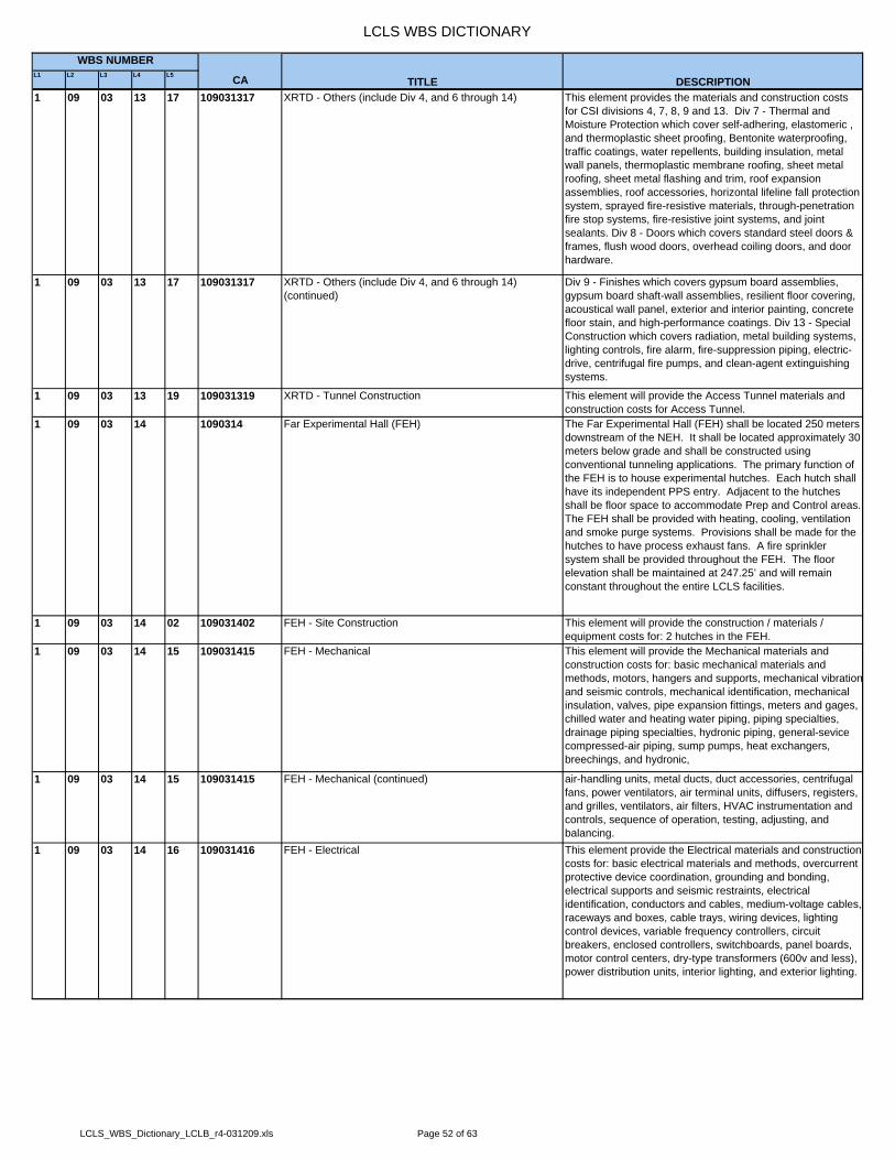
LCLS WBS DICTIONARY
L1 L2 L3 L4 L5 CA
WBS NUMBER
TITLE DESCRIPTION1 09 03 13 17 109031317 XRTD - Others (include Div 4, and 6 through 14) This element provides the materials and construction costs
for CSI divisions 4, 7, 8, 9 and 13. Div 7 - Thermal and Moisture Protection which cover self-adhering, elastomeric , and thermoplastic sheet proofing, Bentonite waterproofing, traffic coatings, water repellents, building insulation, metal wall panels, thermoplastic membrane roofing, sheet metal roofing, sheet metal flashing and trim, roof expansion assemblies, roof accessories, horizontal lifeline fall protection system, sprayed fire-resistive materials, through-penetration fire stop systems, fire-resistive joint systems, and joint sealants. Div 8 - Doors which covers standard steel doors & frames, flush wood doors, overhead coiling doors, and door hardware.
1 09 03 13 17 109031317 XRTD - Others (include Div 4, and 6 through 14) (continued)
Div 9 - Finishes which covers gypsum board assemblies, gypsum board shaft-wall assemblies, resilient floor covering, acoustical wall panel, exterior and interior painting, concrete floor stain, and high-performance coatings. Div 13 - Special Construction which covers radiation, metal building systems, lighting controls, fire alarm, fire-suppression piping, electric-drive, centrifugal fire pumps, and clean-agent extinguishing systems.
1 09 03 13 19 109031319 XRTD - Tunnel Construction This element will provide the Access Tunnel materials and construction costs for Access Tunnel.
1 09 03 14 1090314 Far Experimental Hall (FEH) The Far Experimental Hall (FEH) shall be located 250 meters downstream of the NEH. It shall be located approximately 30 meters below grade and shall be constructed using conventional tunneling applications. The primary function of the FEH is to house experimental hutches. Each hutch shall have its independent PPS entry. Adjacent to the hutches shall be floor space to accommodate Prep and Control areas. The FEH shall be provided with heating, cooling, ventilation and smoke purge systems. Provisions shall be made for the hutches to have process exhaust fans. A fire sprinkler system shall be provided throughout the FEH. The floor elevation shall be maintained at 247.25’ and will remain constant throughout the entire LCLS facilities.
1 09 03 14 02 109031402 FEH - Site Construction This element will provide the construction / materials / equipment costs for: 2 hutches in the FEH.
1 09 03 14 15 109031415 FEH - Mechanical This element will provide the Mechanical materials and construction costs for: basic mechanical materials and methods, motors, hangers and supports, mechanical vibrationand seismic controls, mechanical identification, mechanical insulation, valves, pipe expansion fittings, meters and gages, chilled water and heating water piping, piping specialties, drainage piping specialties, hydronic piping, general-sevice compressed-air piping, sump pumps, heat exchangers, breechings, and hydronic,
1 09 03 14 15 109031415 FEH - Mechanical (continued) air-handling units, metal ducts, duct accessories, centrifugal fans, power ventilators, air terminal units, diffusers, registers, and grilles, ventilators, air filters, HVAC instrumentation and controls, sequence of operation, testing, adjusting, and balancing.
1 09 03 14 16 109031416 FEH - Electrical This element provide the Electrical materials and construction costs for: basic electrical materials and methods, overcurrent protective device coordination, grounding and bonding, electrical supports and seismic restraints, electrical identification, conductors and cables, medium-voltage cables, raceways and boxes, cable trays, wiring devices, lighting control devices, variable frequency controllers, circuit breakers, enclosed controllers, switchboards, panel boards, motor control centers, dry-type transformers (600v and less), power distribution units, interior lighting, and exterior lighting.
LCLS_WBS_Dictionary_LCLB_r4-031209.xls Page 52 of 63

LCLS WBS DICTIONARY
L1 L2 L3 L4 L5 CA
WBS NUMBER
TITLE DESCRIPTION1 09 03 14 17 109031417 FEH - Others (include Div 4, and 6 through 14) This element provides the materials and construction costs
for CSI divisions 4, 7, 8, 9 and 13. Div 7 - Thermal and Moisture Protection which cover self-adhering, elastomeric , and thermoplastic sheet proofing, Bentonite waterproofing, traffic coatings, water repellents, building insulation, metal wall panels, thermoplastic membrane roofing, sheet metal roofing, sheet metal flashing and trim, roof expansion assemblies, roof accessories, horizontal lifeline fall protection system, sprayed fire-resistive materials, through-penetration fire stop systems, fire-resistive joint systems, and joint sealants. Div 8 - Doors which covers standard steel doors & frames, flush wood doors, overhead coiling doors, and door hardware.
1 09 03 14 17 109031417 FEH - Others (include Div 4, and 6 through 14) (continued)
Div 9 - Finishes which covers gypsum board assemblies, gypsum board shaft-wall assemblies, resilient floor covering, acoustical wall panel, exterior and interior painting, concrete floor stain, and high-performance coatings. Div 13 - Special Construction which covers radiation, metal building systems, lighting controls, fire alarm, fire-suppression piping, electric-drive, centrifugal fire pumps, and clean-agent extinguishing systems.
1 09 03 14 18 109031418 FEH - Access Tunnel This element will provide the Access Tunnel materials and construction costs for Access Tunnel.
1 09 03 14 19 109031419 FEH - Tunnel Construction This element will provide the Access Tunnel materials and construction costs for tunneling.
1 09 03 15 1090315 BTH Service Buildings 2.1, 2.2, and 2.3 (SB BTH) Service Buildings 2.1, 2.2, and 2.3 are included as a pre-engineered buildings and are part of the Beam Transport Hall.The building components include the slab, metal frame, exterior cladding, HVAC and electrical.
1 09 03 15 05 109031505 SB BTH - Metals This element will provide the Metals materials and construction costs for: structural steel, steel joists, steel deck, cold-formed metal framing, metal fabrications, metal stairs, gratings, ornamental metal, ornamental railings, and architectural joint systems.
1 09 03 15 15 109031515 SB BTH - Mechanical This element will provide the Mechanical materials and construction costs for: air handlers, fans, ductwork, chilled and hot water piping, balancing/testing and temperature controls. Plumbing includes a compressed air header, a pumped waste system.
1 09 03 15 16 109031516 SB BTH - Electrical This element provide the Electrical materials and construction costs for: basic electrical materials and methods, overcurrent protective device coordination, grounding and bonding, electrical supports and seismic restraints, electrical identification, conductors and cables, medium-voltage cables, raceways and boxes, cable trays, wiring devices, lighting control devices, variable frequency controllers, circuit breakers, enclosed controllers, switchboards, panel boards, motor control centers, dry-type transformers (600v and less), power distribution units, interior lighting, and exterior lighting.
1 09 03 16 1090316 UH Service Building 3.1 (SB UH) Service Buildings 3.1 included as a pre-engineered building and is part of the Undulator Hall. The building components include the slab, metal frame, exterior cladding, HVAC and Electrical.
1 09 03 16 03 109031603 SB UH - Concrete This element will provide the Concrete materials and installation costs for: castinplace concrete and final linings.
1 09 03 16 05 109031605 SB UH - Metals This element will provide the Metals materials and construction costs for: structural steel, steel joists, steel deck, cold-formed metal framing, metal fabrications, metal stairs, gratings, ornamental metal, ornamental railings, and architectural joint systems.
1 09 03 16 15 109031615 SB UH - Mechanical This element will provide the Mechanical materials and construction costs for: basic mechanical materials and methods, motors, hangers and supports, mechanical vibrationand seismic controls, mechanical identification, mechanical insulation, valves, pipe expansion fittings, meters and gages, chilled water and heating water piping, piping specialties, drainage piping specialties, hydronic piping, general-sevice compressed-air piping, sump pumps, heat exchangers, breechings, and hydronic.
LCLS_WBS_Dictionary_LCLB_r4-031209.xls Page 53 of 63

LCLS WBS DICTIONARY
L1 L2 L3 L4 L5 CA
WBS NUMBER
TITLE DESCRIPTION1 09 03 16 15 109031615 SB UH - Mechanical (continued) air-handling units, metal ducts, duct accessories, centrifugal
fans, power ventilators, air terminal units, diffusers, registers, and grilles, ventilators, air filters, HVAC instrumentation and controls, sequence of operation, testing, adjusting, and balancing.
1 09 03 16 16 109031616 SB UH - Electrical This element provide the Electrical materials and construction costs for: basic electrical materials and methods, overcurrent protective device coordination, grounding and bonding, electrical supports and seismic restraints, electrical identification, conductors and cables, medium-voltage cables, raceways and boxes, cable trays, wiring devices, lighting control devices, variable frequency controllers, circuit breakers, enclosed controllers, switchboards, panel boards, motor control centers, dry-type transformers (600v and less), power distribution units, interior lighting, and exterior lighting.
1 09 03 16 17 109031617 SB UH - Others (include Div 4, and 6 through 14) This element provides the materials and construction costs for CSI divisions 4, 7, 8, 9 and 13. Div 7 - Thermal and Moisture Protection which cover self-adhering, elastomeric , and thermoplastic sheet proofing, Bentonite waterproofing, traffic coatings, water repellents, building insulation, metal wall panels, thermoplastic membrane roofing, sheet metal roofing, sheet metal flashing and trim, roof expansion assemblies, roof accessories, horizontal lifeline fall protection system, sprayed fire-resistive materials, through-penetration fire stop systems, fire-resistive joint systems, and joint sealants. Div 8 - Doors which covers standard steel doors & frames, flush wood doors, overhead coiling doors, and door hardware.
1 09 03 16 17 109031617 SB UH - Others (include Div 4, and 6 through 14) (continued)
Div 9 - Finishes which covers gypsum board assemblies, gypsum board shaft-wall assemblies, resilient floor covering, acoustical wall panel, exterior and interior painting, concrete floor stain, and high-performance coatings. Div 13 - Special Construction which covers radiation, metal building systems, lighting controls, fire alarm, fire-suppression piping, electric-drive, centrifugal fire pumps, and clean-agent extinguishing systems.
1 09 03 17 1090317 FEH Access Tunnel Service Yard (SY FEH) This element provides access to the Far Experimental Hall Tunnel Service Yard. The building components include the slab, metal frame, exterior cladding, HVAC and Electrical.
1 09 03 17 03 109031703 SY FEH - Concrete This element will provide the Concrete materials and installation costs for: castinplace concrete and shotcrete initialand final linings.
1 09 03 17 16 109031716 SY FEH - Electrical This element provide the Electrical materials and construction costs for: basic electrical materials and methods, overcurrent protective device coordination, grounding and bonding, electrical supports and seismic restraints, electrical identification, conductors and cables, medium-voltage cables, raceways and boxes, cable trays, wiring devices, lighting control devices, variable frequency controllers, circuit breakers, enclosed controllers, switchboards, panel boards, motor control centers, dry-type transformers (600v and less), power distribution units, interior lighting, and exterior lighting.
1 09 03 17 17 109031717 SY FEH - Others (include Div 4, and 6 through 14 This element provides the materials and construction costs for CSI divisions 4, 7, 8, 9 and 13. Div 7 - Thermal and Moisture Protection which cover self-adhering, elastomeric , and thermoplastic sheet proofing, Bentonite waterproofing, traffic coatings, water repellents, building insulation, metal wall panels, thermoplastic membrane roofing, sheet metal roofing, sheet metal flashing and trim, roof expansion assemblies, roof accessories, horizontal lifeline fall protection system, sprayed fire-resistive materials, through-penetration fire stop systems, fire-resistive joint systems, and joint sealants. Div 8 - Doors which covers standard steel doors & frames, flush wood doors, overhead coiling doors, and door hardware.
1 09 03 18 1090318 Central Utility Plant (CUP) The Central Utility Plant Support (CUP) includes a single levelsteel structure with metal panel cladding and metal standing seam roof assembly. Interiors include light gauge metal studsand painted drywall.
LCLS_WBS_Dictionary_LCLB_r4-031209.xls Page 54 of 63

LCLS WBS DICTIONARY
L1 L2 L3 L4 L5 CA
WBS NUMBER
TITLE DESCRIPTION1 09 03 18 01 109031801 CUP - Site Preparation/General Requirements This element will provide CCIP insurance, bond, and
mobilization to site.1 09 03 18 02 109031802 CUP - Site Construction This element will provide the cost for construction of gas line.
1 09 03 18 03 109031803 CUP - Concrete This element will provide the Concrete materials and installation costs for: castinplace concrete and final linings.
1 09 03 18 05 109031805 CUP - Metals This element will provide the Metals materials and construction costs for: structural steel, steel joists, steel deck, cold-formed metal framing, metal fabrications, metal stairs, gratings, ornamental metal, ornamental railings, and architectural joint systems.
1 09 03 18 15 109031815 CUP - Mechanical This element will provide the Mechanical materials and construction costs for: basic mechanical materials and methods, motors, hangers and supports, mechanical vibrationand seismic controls, mechanical identification, mechanical insulation, valves, pipe expansion fittings, meters and gages, chilled water and heating water piping, piping specialties, drainage piping specialties, hydronic piping, general-sevice compressed-air piping, sump pumps, heat exchangers, breechings, and hydronic.
1 09 03 18 15 109031815 CUP - Mechanical (continued) air-handling units, metal ducts, duct accessories, centrifugal fans, power ventilators, air terminal units, diffusers, registers, and grilles, ventilators, air filters, HVAC instrumentation and controls, sequence of operation, testing, adjusting, and balancing.
1 09 03 18 16 109031816 CUP - Electrical This element provide the Electrical materials and construction costs for: 12kv construction (MH48 to CUP Substation), and underground electrical duct banks.
1 09 03 18 17 109031817 CUP - Others (include Div 4, and 6 through 14) This element provides the materials and construction costs for CSI divisions 4, 7, 8, 9 and 13. Div 4 - Masonry which covers unit masonry assemblies, Div 7 - Thermal and Moisture Protection which cover self-adhering, elastomeric , and thermoplastic sheet proofing, Bentonite waterproofing, traffic coatings, water repellents, building insulation, metal wall panels, thermoplastic membrane roofing, sheet metal roofing, sheet metal flashing and trim, roof expansion assemblies, roof accessories, horizontal lifeline fall protection system, sprayed fire-resistive materials, through-penetration fire stop systems, fire-resistive joint systems, and joint sealants. Div 8 - Doors which covers standard steel doors & frames, flush wood doors, overhead coiling doors, and door hardware.
1 09 03 18 17 109031817 CUP - Others (include Div 4, and 6 through 14) (continued)
Div 9 - Finishes which covers gypsum board assemblies, gypsum board shaft-wall assemblies, resilient floor covering, acoustical wall panel, exterior and interior painting, concrete floor stain, and high-performance coatings. Div 13 - Special Construction which covers radiation, metal building systems, lighting controls, fire alarm, fire-suppression piping, electric-drive, centrifugal fire pumps, and clean-agent extinguishing systems.
1 09 03 19 1090319 SLAC Space Renovation for LCLS Ops This element will provide for LCLS Office and Lab Space Functionality which includes B028 space improvements and CEH building remodel
1 09 03 19 01 109031901 ED&I of SLAC Space Renovations for LCLS Ops This element will provide the space improvements of existing SLAC Office Space at Building 028 for LCLS use. This element covers the cost of: material, labor, and installation for architectural, civil improvement to the space. Improvement to mechanical, plumbing, HVAC, controls, electrical and lighting, fire protection, furniture, and voice/data networks.
1 09 03 19 02 109031902 Construction of SLAC Space Renovation for LCLS This element will provide the renovation of existing SLAC Office Space at CEH Building for LCLS use. This element covers the cost of: material, labor, and installation for floors to include space conversion to offices, support function areas (no remodeling of existing shop areas), interior improvements, restrooms/shower upgraded for ADA compliance, new elevator, stair and exterior walkway.
1 09 03 20 1090320 Project Close Out - Conventional Facilities System This element provide the Conventional Facilities System Project Close-Out for Turner and non-Turner Construction activities.
LCLS_WBS_Dictionary_LCLB_r4-031209.xls Page 55 of 63

LCLS WBS DICTIONARY
L1 L2 L3 L4 L5 CA
WBS NUMBER
TITLE DESCRIPTION1 09 03 20 01 109032001 Non-Turner Trade Project Close Out This element will cover the receipt, inspection, assembly,
commissioning, testing, punchlist, and furnishing of the project facilities and hardware, as well as any approved changes that are required during construction or assembly. Included in this final phase will be the receipt of operating andmaintenance manuals, testing and on-site training for maintenance personnel, as-builts, and start-up of all equipment for validation of project (specification and drawing) compliance. At the end of the close out phase, the project willbe ready for activation and operation by the operations staff.
1 09 03 20 02 109032002 Turner Trade Project Close Out This element will cover the receipt, inspection, assembly, commissioning, testing, punchlist, and furnishing of the project facilities and hardware, as well as any approved changes that are required during construction or assembly. Included in this final phase will be the receipt of operating andmaintenance manuals, testing and on-site training for maintenance personnel, as-builts, and start-up of all equipment for validation of project (specification and drawing) compliance. At the end of the close out phase, the project willbe ready for activation and operation by the operations staff.
2 2 LCLS PROJECT - R&D, SPARES, COMMISSIONING This summary WBS covers the Other Project Cost (OPC) Estimate for the LCLS Project being constructed at SLAC. The LCLS OPC is supported through Research & Development (R&D), Spares and Commissioning funds by the U.S. Department of Energy.
2 01 201 LCLS PROJECT MGMT, PLANNING & ADMN (OPC) This summary WBS covers the Other Project Cost (OPC) Estimate for the LCLS Project being constructed at SLAC. The LCLS OPC is supported through Research & Development (R&D), Spares and Commissioning funds by the U.S. Department of Energy.
2 01 01 20101 LCLS Commissioning Mgmt & Physics Support This summary WBS provides for physics support through the LCLS R&D and commissioning phases of the project.
2 01 01 01 2010101 LCLS Commissioning Management This WBS provides for global physics support through the LCLS R&D and commissioning phases of the project. This will provide support for the LCLS Physics Group Leader who is responsible for directing the overall physics effort for the LCLS project, and provides direction and guidance to the LCLS System Physicists to ensure that LCLS System Requirements meet the needs of the LCLS.
2 01 01 02 2010102 Injector Physics This WBS provides support for the LCLS Injector System Physicist through the R&D and commissioning phases of the LCLS Injector System. The Injector System Physicist is responsible for directing the overall physics effort for the LCLS Injector system and for providing system requirements that satisfy the global requirements of the LCLS project.
2 01 01 03 2010103 Linac Physics This WBS provides support for the LCLS Linac System Physicist through the R&D and commissioning phases of the LCLS Injector System. The Linac System Physicist is responsible for directing the overall physics effort for the LCLS Linac system and for providing system requirements that satisfy the global requirements of the LCLS project.
2 01 01 04 2010104 Undulator Physics This WBS provides support for the LCLS Undulator System Physicist through the R&D and commissioning phases of the LCLS Injector System. The Undulator System Physicist is responsible for directing the overall physics effort for the LCLS Undulator system and for providing system requirements that satisfy the global requirements of the LCLS project.
2 01 01 05 2010105 X-Ray Transport Physics This WBS provides support for the LCLS X-Ray Transport System Physicist through the R&D and commissioning phases of the LCLS X-Ray Transport System. The X-Ray Transport System Physicist is responsible for directing the overall physics effort for the LCLS X-Ray Transport system and for providing system requirements that satisfy the global requirements of the LCLS project.
LCLS_WBS_Dictionary_LCLB_r4-031209.xls Page 56 of 63

LCLS WBS DICTIONARY
L1 L2 L3 L4 L5 CA
WBS NUMBER
TITLE DESCRIPTION2 01 01 06 2010106 X-Ray Physics Commissioning This WBS provides support for the LCLS X-Ray Endstations
System Physicist through the R&D and commissioning phases of the LCLS X-Ray Endstations System. The X-Ray Endstations System Physicist is responsible for directing the overall physics effort for the LCLS X-Ray Endstations system and for providing system requirements that satisfy the global requirements of the LCLS project.
2 01 01 07 2010107 Conventional Facilities Physics This WBS provides support for the LCLS Conventional Facilities System Physicist through the R&D and commissioning phases of the LCLS Conventional Facilities System. The Linac Conventional Facilities Physicist is responsible for directing the overall physics effort for the LCLS Conventional Facilities system and for providing systemrequirements that satisfy the global requirements of the LCLS project.
2 01 01 08 2010108 Consulting Physics (Collaboration) This WBS provides for physicist support and consultation through the R&D and commissioning phases of the LCLS, such as analytic and numerical computations of the SASE process in the LCLS, optimization of the LCLS design, modeling predictions of FEL performance to support modifications for self-seeding operation of the FEL. Also, ad hoc computer modeling programs in support of the LCLS commission effort are included.
2 01 01 09 2010109 Consulting Physics (SLAC) This WBS provides for physicist support and consultation through the R&D and commissioning phases of the LCLS, such as analytic and numerical computations of the electron beam emittance, bunch length, bunch charge, and full-length LCLS (electron to photon) simulation studies to optimize the commissioning of the LCLS are included.
2 01 01 10 2010110 Global Controls Physics Liaison This WBS provides support for the LCLS Global Controls Physicist through the R&D and commissioning phases of the LCLS. The LCLS Global Controls Physicist is responsible for directing the overall physics controls effort for the LCLS and for providing control system requirements that satisfy the global requirements of the LCLS project.
2 01 01 11 2010111 Global Controls OPC This is all non-recurring development for the first instance of each subsystem solution.
2 01 01 11 02 201011102 LLRF Controls Control Account has been moved to Injector and LINAC OPC.
2 01 01 11 11 201011111 Global Controls Commissioning Support machine commissioning of the control system including: test support, revisions from operational experience, and problem resolution.
2 01 01 11 12 201011112 Global Controls Management - OPC Management support2 01 01 11 13 201011113 SLC Aware IOC Design and implementation of the software to emulate the
SLC micro communication inside the EPICS IOC to allow the existing high level applications on SLC to be used for early commissioning and operation.
2 01 01 11 15 201011115 Controls S/W Applications LOE Network and Data Communications for the LCLS project.2 01 01 12 2010112 E-Beam Systems Commissioning Management Management support for the commissioning of electron
beams systems. Commissioning begins after installation and ends when commissioning goals are met and the system is operational.
2 01 01 13 2010113 E-Beam Systems Physics Support Physicist support for the commissioning of electron beams systems. Commissioning begins after installation and ends when commissioning goals are met and the system is operational.
2 01 01 14 2010114 Laser Commissioning Management Management support for the commissioning of laser systems. Commissioning begins after installation and ends when commissioning goals are met and the system is operational.
2 01 02 20102 R&D Studies & Prototyping This WBS provides support for building new timing and RF boards. Both the timing boards and the RF boards require VME architecture to interface with the existing SLAC timing system and the existing SLAC klystron infrastructure.
2 01 02 01 2010201 R&D Studies & Prototyping This WBS provides support for building new timing and RF boards. Both the timing boards and the RF boards require VME architecture to interface with the existing SLAC timing system and the existing SLAC klystron infrastructure.
LCLS_WBS_Dictionary_LCLB_r4-031209.xls Page 57 of 63

LCLS WBS DICTIONARY
L1 L2 L3 L4 L5 CA
WBS NUMBER
TITLE DESCRIPTION2 01 03 20103 Project Mgmnt, Planning and Admn - M&S (OPC) This summary WBS covers the Other Project Cost for the
LCLS Project Office at SLAC.2 01 03 01 2010301 SLAC Project Office - General This WBS covers a portion of the Project Office staff to
manage and direct R&D, Spares and Pre-Operations activities.
2 01 03 02 2010302 SLAC Project Support This WBS covers a portion of the Project Support staff to manage and direct R&D, Spares and Pre-Operations activities.
2 01 03 03 2010303 Project Mgmnt, Planning and Admn - M&S (OPC) This WBS covers the pre-operations activities for the LCLS, which include electrical power usage, start-up costs and Linaclegacy costs during the commissioning phase of the LCLS.
2 02 202 Injector System (OPC) Other Project Costs (OPC) Summary for the Injector System. It includes effort and costs associated with R&D, Spares, and Commissioning.
2 02 02 20202 Injector Controls Subsystem System Summary2 02 02 01 2020201 Personnel Protection System (PPS) R&D This element covers commissioning costs for this system.2 02 02 02 2020202 Beam Containment Subsystem (BCS) This element covers commissioning costs for this system.2 02 02 03 2020203 Machine Protection Subsystem (MPS) This element covers commissioning costs for this system.2 02 02 04 2020204 Power Conv (beamline pwr supp) Spares This element covers spares costs for this system.2 02 02 05 2020205 LLRF Controls This element covers commissioning costs for this system.2 02 02 05 01 202020501 LLRF Controls This element covers commissioning costs for this system.2 02 02 06 2020206 Wire Scanners This element covers commissioning costs for this system.2 02 02 06 01 202020601 Wire Scanners This element covers commissioning costs for this system.2 02 02 06 02 202020602 Controls - BPM Processor Module This element covers commissioning costs for this system.2 02 02 06 03 202020603 Controls - Toroids This element covers commissioning costs for this system.2 02 02 06 05 202020605 Controls - Profile Monitors This element covers commissioning costs for this system.2 02 02 06 12 202020612 Controls - Movable Collimator This element covers commissioning costs for this system.2 02 02 06 14 202020614 Controls - Faraday Cup This element covers commissioning costs for this system.2 02 02 08 2020208 Timing Controls This element covers commissioning costs for this system.2 02 02 09 2020209 Vacuum Controls This element covers commissioning costs for this system.2 02 03 20203 Injector Lasers System Summary2 02 03 01 2020301 Drive Laser Prototyping This element covers special processing spares required for
this section.2 02 03 02 2020302 Drive Laser System This element covers special processing spares required for
this section.2 02 03 03 2020303 Drive Laser Diagnostics This element covers special processing spares required for
this section.2 02 03 14 2020314 LSR HTR - Beam Conditioning Optics (Laser Bay) This element covers special processing spares required for
this section.2 02 03 17 2020317 Reliability Improvement Laser This element covers an additional pump laser to improve the
reliability and maintenance costs of the drive laser.2 02 04 20204 Injector RF Subsystem System Summary2 02 04 01 2020401 RF Gun & Load Lock This element covers special processing spares required for
this section.2 02 04 01 01 202040101 RF Gun This element covers special processing spares required for
this section.2 02 04 01 02 202040102 RF Gun Supports This element covers special processing spares required for
this section.2 02 04 02 2020402 Cathode Processing (CP) Station This element covers special processing spares required for
this section.2 02 04 02 02 202040202 CP Load Lock This element covers special processing spares required for
this section.2 02 04 05 2020405 Injector RF Waveguide Subsystem This element covers special processing spares required for
this section.2 02 04 05 02 202040502 RF Waveguide Supports This element covers special processing spares required for
this section.2 02 04 06 2020406 Injector Linac Structures This element covers special processing spares required for
this section.
LCLS_WBS_Dictionary_LCLB_r4-031209.xls Page 58 of 63
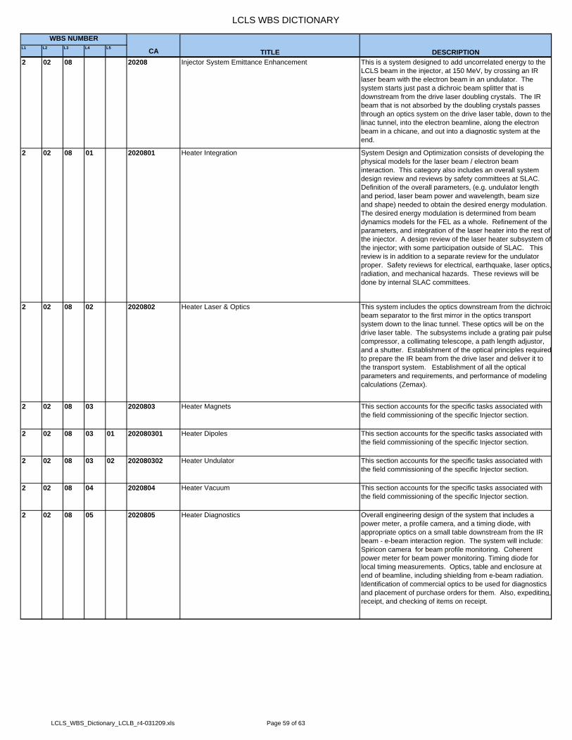
LCLS WBS DICTIONARY
L1 L2 L3 L4 L5 CA
WBS NUMBER
TITLE DESCRIPTION2 02 08 20208 Injector System Emittance Enhancement This is a system designed to add uncorrelated energy to the
LCLS beam in the injector, at 150 MeV, by crossing an IR laser beam with the electron beam in an undulator. The system starts just past a dichroic beam splitter that is downstream from the drive laser doubling crystals. The IR beam that is not absorbed by the doubling crystals passes through an optics system on the drive laser table, down to the linac tunnel, into the electron beamline, along the electron beam in a chicane, and out into a diagnostic system at the end.
2 02 08 01 2020801 Heater Integration System Design and Optimization consists of developing the physical models for the laser beam / electron beam interaction. This category also includes an overall system design review and reviews by safety committees at SLAC. Definition of the overall parameters, (e.g. undulator length and period, laser beam power and wavelength, beam size and shape) needed to obtain the desired energy modulation. The desired energy modulation is determined from beam dynamics models for the FEL as a whole. Refinement of the parameters, and integration of the laser heater into the rest of the injector. A design review of the laser heater subsystem ofthe injector; with some participation outside of SLAC. This review is in addition to a separate review for the undulator proper. Safety reviews for electrical, earthquake, laser optics,radiation, and mechanical hazards. These reviews will be done by internal SLAC committees.
2 02 08 02 2020802 Heater Laser & Optics This system includes the optics downstream from the dichroic beam separator to the first mirror in the optics transport system down to the linac tunnel. These optics will be on the drive laser table. The subsystems include a grating pair pulsecompressor, a collimating telescope, a path length adjustor, and a shutter. Establishment of the optical principles requiredto prepare the IR beam from the drive laser and deliver it to the transport system. Establishment of all the optical parameters and requirements, and performance of modeling calculations (Zemax).
2 02 08 03 2020803 Heater Magnets This section accounts for the specific tasks associated with the field commissioning of the specific Injector section.
2 02 08 03 01 202080301 Heater Dipoles This section accounts for the specific tasks associated with the field commissioning of the specific Injector section.
2 02 08 03 02 202080302 Heater Undulator This section accounts for the specific tasks associated with the field commissioning of the specific Injector section.
2 02 08 04 2020804 Heater Vacuum This section accounts for the specific tasks associated with the field commissioning of the specific Injector section.
2 02 08 05 2020805 Heater Diagnostics Overall engineering design of the system that includes a power meter, a profile camera, and a timing diode, with appropriate optics on a small table downstream from the IR beam - e-beam interaction region. The system will include: Spiricon camera for beam profile monitoring. Coherent power meter for beam power monitoring. Timing diode for local timing measurements. Optics, table and enclosure at end of beamline, including shielding from e-beam radiation. Identification of commercial optics to be used for diagnostics and placement of purchase orders for them. Also, expediting,receipt, and checking of items on receipt.
LCLS_WBS_Dictionary_LCLB_r4-031209.xls Page 59 of 63
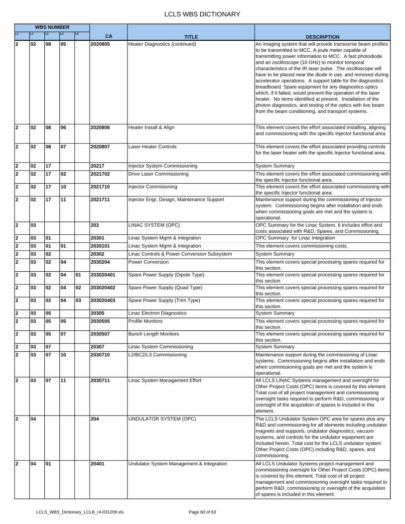
LCLS WBS DICTIONARY
L1 L2 L3 L4 L5 CA
WBS NUMBER
TITLE DESCRIPTION2 02 08 05 2020805 Heater Diagnostics (continued) An imaging system that will provide transverse beam profiles
to be transmitted to MCC. A joule meter capable of transmitting power information to MCC. A fast photodiode and an oscilloscope (10 GHz) to monitor temporal characteristics of the IR laser pulse. The oscilloscope will have to be placed near the diode in use, and removed during accelerator operations. A support table for the diagnostics breadboard. Spare equipment for any diagnostics optics which, if it failed, would prevent the operation of the laser heater. No items identified at present. Installation of the photon diagnostics, and testing of the optics with live beam from the beam conditioning, and transport systems.
2 02 08 06 2020806 Heater Install & Align This element covers the effort associated installing, aligning and commissioning with the specific Injector functional area.
2 02 08 07 2020807 Laser Heater Controls This element covers the effort associated providing controls for the laser heater with the specific Injector functional area.
2 02 17 20217 Injector System Commissioning System Summary2 02 17 02 2021702 Drive Laser Commissioning This element covers the effort associated commissioning with
the specific Injector functional area.2 02 17 10 2021710 Injector Commisioning This element covers the effort associated commissioning with
the specific Injector functional area.2 02 17 11 2021711 Injector Engr, Design, Maintenance Support Maintenance support during the commissioning of Injector
system. Commissioning begins after installation and ends when commissioning goals are met and the system is operational.
2 03 203 LINAC SYSTEM (OPC) OPC Summary for the Linac System. It includes effort and costs associated with R&D, Spares, and Commissioning.
2 03 01 20301 Linac System Mgmt & Integration OPC Summary for Linac Integration2 03 01 01 2030101 Linac System Mgmt & Integration This element covers commissioning costs.2 03 02 20302 Linac Controls & Power Conversion Subsystem System Summary2 03 02 04 2030204 Power Conversion This element covers special processing spares required for
this section.2 03 02 04 01 203020401 Spare Power Supply (Dipole Type) This element covers special processing spares required for
this section.2 03 02 04 02 203020402 Spare Power Supply (Quad Type) This element covers special processing spares required for
this section.2 03 02 04 03 203020403 Spare Power Supply (Trim Type) This element covers special processing spares required for
this section.2 03 05 20305 Linac Electron Diagnostics System Summary2 03 05 05 2030505 Profile Monitors This element covers special processing spares required for
this section.2 03 05 07 2030507 Bunch Length Monitors This element covers special processing spares required for
this section.2 03 07 20307 Linac System Commissioning System Summary2 03 07 10 2030710 L2/BC2/L3 Commissioning Maintenance support during the commissioning of Linac
systems. Commissioning begins after installation and ends when commissioning goals are met and the system is operational.
2 03 07 11 2030711 Linac System Management Effort All LCLS LINAC Systems management and oversight for Other Project Costs (OPC) items is covered by this element. Total cost of all project management and commissioning oversight tasks required to perform R&D, commissioning or oversight of the acquisition of spares is included in this element.
2 04 204 UNDULATOR SYSTEM (OPC) The LCLS Undulator System OPC area for spares plus any R&D and commissioning for all elements including undulator magnets and supports, undulator diagnostics, vacuum systems, and controls for the undulator equipment are included herein. Total cost for the LCLS undulator system Other Project Costs (OPC) including R&D, spares, and commissioning.
2 04 01 20401 Undulator System Management & Integration All LCLS Undulator Systems project management and commissioning oversight for Other Project Costs (OPC) items is covered by this element. Total cost of all project management and commissioning oversight tasks required to perform R&D, commissioning or oversight of the acquisition of spares is included in this element.
LCLS_WBS_Dictionary_LCLB_r4-031209.xls Page 60 of 63
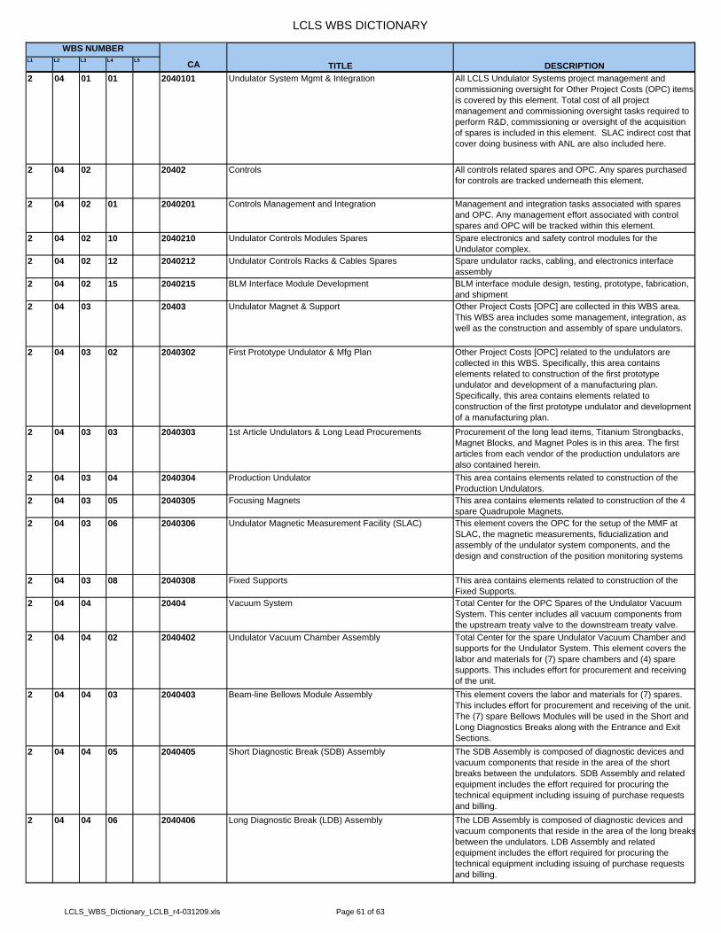
LCLS WBS DICTIONARY
L1 L2 L3 L4 L5 CA
WBS NUMBER
TITLE DESCRIPTION2 04 01 01 2040101 Undulator System Mgmt & Integration All LCLS Undulator Systems project management and
commissioning oversight for Other Project Costs (OPC) items is covered by this element. Total cost of all project management and commissioning oversight tasks required to perform R&D, commissioning or oversight of the acquisition of spares is included in this element. SLAC indirect cost that cover doing business with ANL are also included here.
2 04 02 20402 Controls All controls related spares and OPC. Any spares purchased for controls are tracked underneath this element.
2 04 02 01 2040201 Controls Management and Integration Management and integration tasks associated with spares and OPC. Any management effort associated with control spares and OPC will be tracked within this element.
2 04 02 10 2040210 Undulator Controls Modules Spares Spare electronics and safety control modules for the Undulator complex.
2 04 02 12 2040212 Undulator Controls Racks & Cables Spares Spare undulator racks, cabling, and electronics interface assembly
2 04 02 15 2040215 BLM Interface Module Development BLM interface module design, testing, prototype, fabrication, and shipment
2 04 03 20403 Undulator Magnet & Support Other Project Costs [OPC] are collected in this WBS area. This WBS area includes some management, integration, as well as the construction and assembly of spare undulators.
2 04 03 02 2040302 First Prototype Undulator & Mfg Plan Other Project Costs [OPC] related to the undulators are collected in this WBS. Specifically, this area contains elements related to construction of the first prototype undulator and development of a manufacturing plan. Specifically, this area contains elements related to construction of the first prototype undulator and development of a manufacturing plan.
2 04 03 03 2040303 1st Article Undulators & Long Lead Procurements Procurement of the long lead items, Titanium Strongbacks, Magnet Blocks, and Magnet Poles is in this area. The first articles from each vendor of the production undulators are also contained herein.
2 04 03 04 2040304 Production Undulator This area contains elements related to construction of the Production Undulators.
2 04 03 05 2040305 Focusing Magnets This area contains elements related to construction of the 4 spare Quadrupole Magnets.
2 04 03 06 2040306 Undulator Magnetic Measurement Facility (SLAC) This element covers the OPC for the setup of the MMF at SLAC, the magnetic measurements, fiducialization and assembly of the undulator system components, and the design and construction of the position monitoring systems
2 04 03 08 2040308 Fixed Supports This area contains elements related to construction of the Fixed Supports.
2 04 04 20404 Vacuum System Total Center for the OPC Spares of the Undulator Vacuum System. This center includes all vacuum components from the upstream treaty valve to the downstream treaty valve.
2 04 04 02 2040402 Undulator Vacuum Chamber Assembly Total Center for the spare Undulator Vacuum Chamber and supports for the Undulator System. This element covers the labor and materials for (7) spare chambers and (4) spare supports. This includes effort for procurement and receiving of the unit.
2 04 04 03 2040403 Beam-line Bellows Module Assembly This element covers the labor and materials for (7) spares. This includes effort for procurement and receiving of the unit. The (7) spare Bellows Modules will be used in the Short and Long Diagnostics Breaks along with the Entrance and Exit Sections.
2 04 04 05 2040405 Short Diagnostic Break (SDB) Assembly The SDB Assembly is composed of diagnostic devices and vacuum components that reside in the area of the short breaks between the undulators. SDB Assembly and related equipment includes the effort required for procuring the technical equipment including issuing of purchase requests and billing.
2 04 04 06 2040406 Long Diagnostic Break (LDB) Assembly The LDB Assembly is composed of diagnostic devices and vacuum components that reside in the area of the long breaksbetween the undulators. LDB Assembly and related equipment includes the effort required for procuring the technical equipment including issuing of purchase requests and billing.
LCLS_WBS_Dictionary_LCLB_r4-031209.xls Page 61 of 63
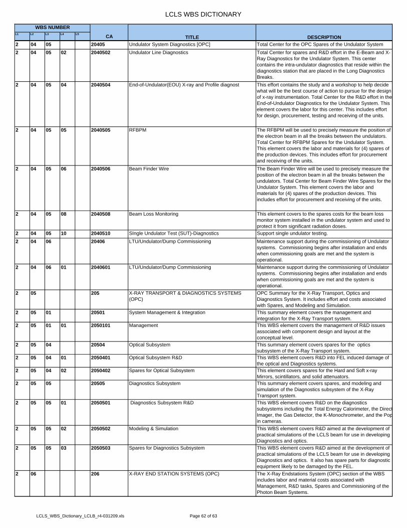
LCLS WBS DICTIONARY
L1 L2 L3 L4 L5 CA
WBS NUMBER
TITLE DESCRIPTION2 04 05 20405 Undulator System Diagnostics [OPC] Total Center for the OPC Spares of the Undulator System2 04 05 02 2040502 Undulator Line Diagnostics Total Center for spares and R&D effort in the E-Beam and X-
Ray Diagnostics for the Undulator System. This center contains the intra-undulator diagnostics that reside within the diagnostics station that are placed in the Long Diagnostics Breaks.
2 04 05 04 2040504 End-of-Undulator(EOU) X-ray and Profile diagnost This effort contains the study and a workshop to help decide what will be the best course of action to pursue for the design of x-ray instrumentation. Total Center for the R&D effort in the End-of-Undulator Diagnostics for the Undulator System. This element covers the labor for this center. This includes effort for design, procurement, testing and receiving of the units.
2 04 05 05 2040505 RFBPM The RFBPM will be used to precisely measure the position of the electron beam in all the breaks between the undulators. Total Center for RFBPM Spares for the Undulator System. This element covers the labor and materials for (4) spares of the production devices. This includes effort for procurement and receiving of the units.
2 04 05 06 2040506 Beam Finder Wire The Beam Finder Wire will be used to precisely measure the position of the electron beam in all the breaks between the undulators. Total Center for Beam Finder Wire Spares for the Undulator System. This element covers the labor and materials for (4) spares of the production devices. This includes effort for procurement and receiving of the units.
2 04 05 08 2040508 Beam Loss Monitoring This element covers to the spares costs for the beam loss monitor system installed in the undulator system and used to protect it from significant radiation doses.
2 04 05 10 2040510 SIngle Undulator Test (SUT)-Diagnostics Support single undulator testing.2 04 06 20406 LTU/Undulator/Dump Commissioning Maintenance support during the commissioning of Undulator
systems. Commissioning begins after installation and ends when commissioning goals are met and the system is operational.
2 04 06 01 2040601 LTU/Undulator/Dump Commissioning Maintenance support during the commissioning of Undulator systems. Commissioning begins after installation and ends when commissioning goals are met and the system is operational.
2 05 205 X-RAY TRANSPORT & DIAGNOSTICS SYSTEMS (OPC)
OPC Summary for the X-Ray Transport, Optics and Diagnostics System. It includes effort and costs associated with Spares, and Modeling and Simulation.
2 05 01 20501 System Management & Integration This summary element covers the management and integration for the X-Ray Transport system.
2 05 01 01 2050101 Management This WBS element covers the management of R&D issues associated with component design and layout at the conceptual level.
2 05 04 20504 Optical Subsystem This summary element covers spares for the optics subsystem of the X-Ray Transport system.
2 05 04 01 2050401 Optical Subsystem R&D This WBS element covers R&D into FEL induced damage of the optical and Diagnostics systems.
2 05 04 02 2050402 Spares for Optical Subsystem This element covers spares for the Hard and Soft x-ray Mirrors, scintillators, and solid attenuators.
2 05 05 20505 Diagnostics Subsystem This summary element covers spares, and modeling and simulation of the Diagnostics subsystem of the X-Ray Transport system.
2 05 05 01 2050501 Diagnostics Subsystem R&D This WBS element covers R&D on the diagnostics subsystems including the Total Energy Calorimeter, the DirectImager, the Gas Detector, the K-Monochrometer, and the Popin cameras.
2 05 05 02 2050502 Modeling & Simulation This WBS element covers R&D aimed at the development of practical simulations of the LCLS beam for use in developing Diagnostics and optics.
2 05 05 03 2050503 Spares for Diagnostics Subsystem This WBS element covers R&D aimed at the development of practical simulations of the LCLS beam for use in developing Diagnostics and optics. It also has spare parts for diagnostic equipment likely to be damaged by the FEL.
2 06 206 X-RAY END STATION SYSTEMS (OPC) The X-Ray Endstations System (OPC) section of the WBS includes labor and material costs associated with Management, R&D tasks, Spares and Commissioning of the Photon Beam Systems.
LCLS_WBS_Dictionary_LCLB_r4-031209.xls Page 62 of 63

LCLS WBS DICTIONARY
L1 L2 L3 L4 L5 CA
WBS NUMBER
TITLE DESCRIPTION2 06 01 20601 XE System Mgmt & Integration This element provides management support and travel for the
Photon Beam Systems. It also includes the effort associated with integrating, testing and commissioning of all the subsystems of the Photon Beam Systems.
2 06 02 20602 Controls Subsystem This element covers the controls R&D.2 06 02 04 2060204 LBNL Laser Timing This element covers the controls R&D effort by LBNL for the
LCLS laser timing system.2 06 02 08 2060208 2-D X-Ray Detector Controls This element covers the controls effort for the 2D x-ray
detector, in particular the integration with data read out and display.
2 06 03 20603 Commissioning Commissioning of FEE diagnostics systems in support of undulator commissioning. Flux measurement in the FEE. Transport and characterization of photon beam into NEH, XRT, and FEH. This includes commissioning of AMO experiment. Commissioning ends when photons are detectedin the Far Experimental Hall.
2 06 04 20604 Spares This element includes procurement and assembly of spare parts for the X-Ray Endstation Systems.
2 06 04 01 2060401 Spares - PPS Stoppers This element includes procurement and assembly of spare PPS stoppers.
2 06 05 20605 X-Ray Detectors This element includes the R&D activites associated with delivering a novel 2D x-ray detector. All the effort in this WBs section is managed via a contract with Cornell University.
2 06 05 02 2060502 2-D X-Ray Detector This element includes labor and materials for the 2D x-ray detector contract with Cornell. It also covers the biannual external detector reviews by the LCLS detector advisory committee (LDAC).
2 06 07 20607 AMO - HFP Instrument This element includes labor and materials of componnents forthe AMO instrument needed for the operation phase of LCLS.
2 06 07 01 2060701 AMO - HFP Instrument- TOF Storage chamber This element includes labor and materials for providing a separate chamber for storing the Time of Flight (TOF) spectrometers under vacuum when not in use for experimentsat the AMO High field instrument.
2 06 10 20610 SXR Instrument This element includes labor to for integration of SXR and to insure proper installation of SXR systems to LCLS standards.
2 06 10 01 2061001 SXR Management & Design This element includes labor for integration SXR systems into the LCLS, Radiation Physics evaluations of the SXR systems and reviews of SXR systems.
2 06 10 02 2061002 SXR Installation This element includes labor for inspection, fiducialization and alignment to insure proper installation of the SXR systems.
2 09 03 20903 Beam Path Project Commissioning This element covers the commissioning plan, Dispute Resolution, and OPC Labor Support to Beam Path
2 09 03 05 2090305 Beam Path Project Commissioning This element covers the commissioning plan, Dispute Resolution, and OPC Labor Support to Beam Path
LCLS_WBS_Dictionary_LCLB_r4-031209.xls Page 63 of 63