lcc - maintenance...lcc - metal lcc - rubber ksb ag bahnhofplatz 1 d-91257 pegnitz, germany (0 92...
TRANSCRIPT
LCC
LCC-Metal LCC-Rubber
Pump Type: Pump Serial Number:
Date:
Purchaser:
Purchaser’s Order Number:
GIW Work Order Number:
Shipped To:
Maintenance Manual 2368.8000/A10-14 G2 (03/30/05.0)
A KSB Company
GIW INDUSTRIES, INC. 5000 Wrightsboro Road Grovetown, GA 30813 USA
(706) 863-1011 FAX (706) 855-5151
KSB S.A. 10/14, rue de la Gare F-76250 Déville-lès-Rouen, FRANCE
32 82-32 00 FAX 32 82-32 90
Slurry Pumps
LCC - Metal LCC - Rubber
KSB AG Bahnhofplatz 1 D-91257 Pegnitz, GERMANY
(0 92 41) 71-0 FAX (0 92 41) 71-17 91
Include the pump’s serial number when ordering replacement parts
. Note: This is a standard maintenance manual provided for your convenience. This manual may not be reproduced without written consent of GIW Industries. Additional copies may be purchased. Please contact your sales representative for details.

LCC
2
Contents Page
Maintenance Manual 1
1 General 5
2 Safety 5 2.1 Marking of Instructions in the Manual 5 2.2 Personnel Qualification and Training 5 2.3 Non-compliance with Safety Instructions 5 2.4 Safety Awareness 5 2.5 Safety Instructions for the Operator / User 5 2.6 Safety Instructions for Maintenance,
Inspection and Installation 6 2.7 Unauthorized Modification and Manufacture of
Spare Parts 6 2.8 Unauthorized Modes of Operation 6
3 Transport and Interim Storage 6 3.1 Transport 6 3.2 Short Term Storage 6
4 Description of the Product and Accessories 7 4.1 Technical Specification 7 4.2 Designation 7 4.3 Design Details 7 4.3.1 Pump Casing 7 4.3.2 Impeller Form 8 4.3.3 Shaft Seal 8 4.3.4 Bearings 9 4.3.5 Permissible Forces and Moments at the Pump
Nozzles 9 4.3.5 Permissible Forces and Moments at the Pump
Nozzles 10 4.3.6 Noise Characteristics 10 4.5 Dimensions and Weights 10
5 Installation at Site 10 5.1 Safety Regulations 10 5.2 Foundation 11 5.3 Installing the Pump / Unit 11 5.3.1 Aligning the Pump / Drive Train 11 5.3.2 Place of Installation 11 5.4 Connecting the Piping 11 5.4.1 Auxiliary Connections 12 5.4.2 Safety Guards 12 5.5 Final Check 12 5.6 Connection to Power Supply 12
6 Commissioning, Start-up / Shutdown 12 6.1 Commissioning 12 6.1.1 Lubricants 12 6.1.2 Shaft Seal 13 6.1.3 Priming the Pump and Other Checks 13 6.1.4 Checking the Direction of Rotation 13 6.1.5 Cleaning the Plant Piping 13 6.1.6 Suction Strainer 13 6.1.7 Start-up 14
6.1.8 Shutdown 14 6.2 Operating Limits 14 6.2.1 Temperature of the Medium Handled, Ambient
Temperature, Bearing Temperature 14 6.2.2 Switching Frequency 14 6.2.3 Density of the Medium Handled 14 6.3 Shutdown / Storage / Preservation 14 6.3.1 Storage of New Pumps 14 6.3.2 Measures to be taken for Prolonged Shutdown14 6.3.3 Storage of Elastomer Linings 15 6.4 Returning to Service after Storage 15
7 Maintenance /Repair 15 7.1 General Instructions 15 7.2 Maintenance / Inspection 15 7.2.1 Supervision of Operation 15 7.2.2 Lubrication and Lubricant Change 15 7.2.2.1 Lubrication 15 7.2.2.2 Grease Quality / Grease Changes 15 7.2.2.3 Oil Changes 16 7.3 Drainage / Disposal 16 7.4 Dismantling 16 7.4.1 Sectional Drawings and Bills of Material 16 7.4.2 Dismantling Procedures Impeller 16 7.5 Reassembly 17 7.5.1 General Instructions 17 7.5.2 Mounting of Bearings 18 7.5.3 Inserting Shaft and Bearings into Housing 18 7.5.4 Installing End Covers and Seals 18 7.5.5 Mounting Shaft Sleeve 19 7.5.6 Mounting Stuffing Box 19 7.5.6.1 Stuffing Box 19 7.5.6.2 Packing (non-expeller) 19 7.5.6.3 Packing (expeller) 19 7.5.7 Mounting the Bearing Assembly to Pedestal 19 7.5.8 Metal Expeller Assembly 20 7.5.9 Mounting Shell 20 7.5.10 Elastomer Lined Wet End 20 7.5.11 Impeller 20 7.5.12 Suction Plate and Liner ( LCC-H only) 20 7.5.13 Axial Adjustment of the Bearing Housing 20 7.5.14 Expeller Running Clearance 21 7.5.15 Tightening Torques 21 7.5.16 Water Purge for Gland Packing 21 7.6 Spare Parts Stock 22 7.6.1 Maintenance Procedures for Maximum Parts
Life 22 7.7 Operational Problems and Solutions 22
8 Trouble Shooting 24
9 Torque Values for Metric Fasteners 26
NOTES 27
10 General Drawing with List of Components 28

LCC
3
11 Supplements 28 11. 1 Stuffing Box Throat Bushing Option 28 11.2 Underwater Pump Operation with Duo-Cone
Bearing Seals 30 11.3 Duo-Cone Seals 31 11.4 Diverter 33
LCC
4
Index Section Page Section Page
Accessories 4.4 ........10 Aligning the Pump / Drive Train 5.3.1 ....11 Bearing Assembly Clamp Bolts 7.5.15 ...21 Bearing Assembly, mounting 7.5.7 ....19 Bearing Housing, Axial Adjustment of 7.5.13 ..20 Bearing, Taper Locknut Assembly Torque 7.5.15 ..21 Bearings 4.3.4 .... 9 Bearings, mounting 7.5.2 .....18 Bills of Material 7.4.1 .....16 Casing 4.3.1 ..... 7 Cavitation / NPSH Performance 7.7 ........23 Check, Final 5.5 .......12 Commissioning 6.1 .......12 Commissioning, Start-up / Shutdown 6 ...........12 Connections, Auxiliary 5.4.1 ....12 Density of the Medium Handled 6.2.3 .....14 Description of the Product and Accessories 4 ........... 7 Design Details 4.3 ....... 7 Dimensions 4.5 ........10 Dismantling 7.4 ........16 Drainage / Disposal 7.3 ........16 Drawing / List of Components 9 ...........28 Drawings , Sectional 7.4.1 .....16 Elastomer Lined Wet End, assembly 7.5.10 ...20 End Covers and Seals, installation 7.5.4 .....18 Expeller Running Clearance, 7.5.14 ..21 Expeller, metal assembly 7.5.8 .....20 General 1 ........... 5 Grease Quality / Grease Changes 7.2.2.2 ..15 Guards, 5.4.2 .....12 Impeller Break-Loose Jig 7.4.2 .....16 Impeller Form 4.3.2 ..... 8 Impeller Lifting Jig 7.4.2 .....16 Impeller, mounting 7.5.11 ...20 Impeller, parts life 7.6.1 ....22 Installation 5.3.2 .....11 Installation at Site 5 ..........10 Installation, Checks to be Carried out 5.2 .......11 Installing the Pump / Unit 5.3 ........11 Lubricants 6.1.1 .....12 Lubrication 7.2.2.1 .15 Lubrication and Lubricant Change 7.2.2 .....15 Maintenance / Inspection 7.2 ........15 Maintenance /Repair 7 ..........15 Maintenance, General Instructions 7.1 .......15 Marking of Instructions in the Manual 2.1 ........ 5 Noise Characteristics 4.3.6 .....10 Oil Changes 7.2.2.3 ..16 Operating Conditions of Flow and Head 7.7 ........23 Operating Limits 6.2 ........14 Operation, Supervision of 7.2.1 ....15
Operation, Unauthorized modes 2.8 ........ 6 Operational Problems and Solutions 7.7 ........22 Packing the gland 7.5.16 ...21 Personnel Qualification and Training 2.2 ........ 5 Piping System Design 7.7 ........23 Piping, Allowable Forces and Moments 4.3.5 .....10 Piping, Cleaning the Plant 6.1.5 .....13 Piping, Connecting the 5.4 ........11 Power Supply, Connection 5.6 ........12 Priming the Pump and Other Checks 6.1.3 .....13 Reassembly , General Instructions 7.5.1 .....17 Reassembly 7.5 ........17 Rotation, Direction of 6.1.4 .....13 Safety 2 ........... 5 Safety Awareness 2.4 ........ 5 Safety Instructions for the Operator / User 2.5 ........ 5 Safety Instructions, for Maintenance 2.6 ....... 6 Safety Instructions, Non-compliance with 2.3 ........ 5 Safety Regulations 5.1 ........10 Seal Water Requirements 7.5.16 ...22 Shaft Seal 4.3.3 ..... 8 Shaft Seal, Commissioning 6.1.2 .....13 Shaft Sleeve, mounting 7.5.5 ....19 Shaft, insertion into Housing 7.5.3 .....18 Shell, mounting 7.5.9 ....20 Shell, parts life 7.6.1 ....22 Shutdown / Storage / Preservation 6.3 ........14 Shutdown 6.1.8 .....14 Shutdown, Prolonged 6.3.2 .....14 Spare Parts Stock 7.6 .......22 Spare Parts, Unauthorized Modification of 2.7 ..... 6 Specifications 4.1 ........ 7 Start-up 6.1.7 .....14 Start-up Strainer 6.1.6 .....13 Storage of Elastomer Linings 6.3.3 .....15 Storage of New Pumps 6.3.1 ....14 Storage, Returning to Service after 6.4 .......15 Storage, /Short term 3.2 ........ 6 Stuffing Box, mounting 7.5.6 .....19 Suction Liner, parts life 7.6.1 .....22 Suction Plate and Liner ( LCC-H only) 7.5.12 ...20 Sump Design 7.7 ........23 Switching Frequency 6.2.2 .....14 Temperature, of Medium Handled 6.2.1 .....14 Tightening Torques 7.5.15 ...21 Transport 3.1 ........ 6 Transport and Interim Storage 3 ........... 6 Trouble Shooting 8 ...........24 Wear Problems and Solutions 7.7 ........22 Wear, Parts Life 7.6.1 ....22 Weights 4.5 ........10

LCC
5
Caution
1 General This manual contains important information
for reliable, proper and efficient operation. Compliance with the operating instructions is of vital importance to ensure reliability and long service life of the pump, and to avoid any risks. These operating instructions do not take into account local regulations; the operator must ensure that such regulations are strictly observed by all, including the personnel called in for installation.
This pump / unit must not be operated beyond the limit values specified in the technical documentation for the medium handled, capacity, speed, density, pressure, temperature and motor rating. Make sure that operation is in accordance with the instructions given in this manual or in the contract documentation. The nameplate indicates the type series / size, main operating data and serial number; please quote this information in all queries, repeat orders and particularly when ordering spare parts. If you need any additional information or instructions exceeding the scope of this manual or in case of damage please contact your GIW / KSB representative. 2 Safety These operating instructions contain fundamental information that must be complied with during installation, operation and maintenance. Therefore this operating manual must be read and understood both by the installing personnel and the responsible trained personnel / operators prior to installation and commissioning, and it must always be kept close to the operating location of the machine / unit for easy access. Not only must the general safety instructions given in this chapter of “Safety” be complied with, but also the safety instructions outlined under specific headings. 2.1 Marking of Instructions in the Manual The safety instructions contained in this manual whose non-observance might cause hazards to persons are specially marked with the general hazard sign, namely
safety sign in accordance with DIN 4844-W9. The electrical danger warning sign is
safety sign in accordance with DIN 4844-W8.
The word
Caution is to introduce safety instructions whose non-observance may lead to damage to the machine and its functions. Instructions attached directly to the machine, such as: • Arrow indicating the direction of rotation • Marking for fluid connections must always be complied with and be kept in legible condition at all times. 2.2 Personnel Qualification and Training All personnel involved in the operation, maintenance, inspection and installation of the machine must be fully qualified to carry out the work involved. Personnel responsibilities, competence and supervision must be clearly defined by the operator. If the personnel in question are not already in possession of the requisite know-how, appropriate training and instruction must be provided. If required, the operator may commission the manufacturer / supplier to provide such training. In addition, the operator is responsible for ensuring that the contents of the operating instructions are fully understood by the responsible personnel. 2.3 Non-compliance with Safety Instructions Non-compliance with safety instructions can jeopardize the safety of personnel, the environment and the machine itself. Non-compliance with these safety instructions will also lead to forfeiture of any and all rights to claims for damages. In particular, non-compliance can, for example, result in: • Failure of important machine / unit functions • Failure of prescribed maintenance and servicing
practices • Hazard to persons by electrical, mechanical and
chemical effects • Hazard to the environment due to leakage of hazardous
substances. 2.4 Safety Awareness It is imperative to comply with the safety instructions contained in this manual, the relevant national and local health and safety regulations and the operator’s own internal work, operation and safety regulations. 2.5 Safety Instructions for the Operator / User • Any hot or cold components that could pose a hazard
must be equipped with a guard by the operator. • Guards that are fitted to prevent accidental contact with
moving parts (e.g. coupling) must not be removed while the machine is operating.
• Leakages (e.g. at the shaft seal) of hazardous media handled (e.g. explosive, toxic, hot) must be contained so as to avoid any danger to persons and the environment. Pertinent legal provisions must be adhered to.
• Electrical hazards must be eliminated. (Refer to the relevant safety regulations applicable to different countries and / or the local energy supply companies.)

LCC
6
Caution
2.6 Safety Instructions for Maintenance, Inspection and Installation
The operator is responsible for ensuring that all maintenance, inspection and installation work is performed by authorized and qualified personnel who are thoroughly familiar with the manual. Work on the machine must be carried out only during standstill. The shutdown procedure described in the manual for taking the machine out of service must be adhered to without fail. Pumps or pump units handling media injurious to health must be decontaminated. Immediately following completion of the work, all safety / protective devices must be re-installed and / or re-activated. Please observe all instructions set out In the chapter on “Commissioning” before returning the machine to service. 2.7 Unauthorized Modification and Manufacture of
Spare Parts Modifications or alterations of the machine are only permitted after consultation with the manufacturer. Original spare parts and accessories authorized by the manufacturer ensure safety. The use of other parts can invalidate any liability of the manufacturer for damage or warranty. 2.8 Unauthorized Modes of Operation Any warranty of the operating reliability and safety of the pump / unit supplied is only valid if the machine is operated in accordance with its designated use as described in the following sections. The limits stated in the data sheet must not be exceeded under any circumstances. 3 Transport and Interim Storage 3.1 Transport Proper lifting and safety practices must be observed at all times. Lifting the pump assembly requires extreme care, since the center of gravity is not located in the physical center of the unit, but is usually closer to the stuffing box / shaft seal area. Never lift by a single point and do not use the pump or motor shaft as a lift point. Eyebolt locations on the bearing assembly and motor are intended for lifting those items only and must not be used to lift the pump assembly. At least four (4) connections are recommended to stabilize the load, and they should be as far apart as practical. Avoid excessive side loads on cast lifting eyes. Note that certain lift points on the pedestal are intended for use in handling the pedestal alone and are not necessarily optimum balance points for the pump assembly. Always make sure that the unit remains in the horizontal position during transport and cannot slip out of the transport suspension arrangement.
If the pump / unit slips out of the suspension arrangement, it may cause personal injury and damage to property.
Figures below give suggested lifting methods. Actual safe lifting method will vary with pump configuration and type of lifting equipment. Ensure secure attachments and test lifting method for stability before moving pump. Fig. 3.1-1 Transport of the pump
WARNING: Very top heavy Fig. 3.1-2 Transport of the complete unit 3.2 Short Term Storage The pump / unit should be stored in a dry room where the atmospheric humidity is as constant as possible. If stored outdoors, the unit and crates must be covered by waterproof material to avoid any contact with humidity. All openings of the assembled pump / unit components are closed and must only be opened when required during installation.
Protect all stored goods against humidity, dirt, vermin and unauthorized access! See Section 6.3 for long term storage requirements.

LCC
7
4 Description of the Product and Accessories
4.1 Technical Specification Centrifugal pump for handling coarse or fine particles from solids-laden waste water to aggressive slurries of an abrasive or corrosive nature. Applications include process pumping and tailings disposal for mining, dredging and other industrial operations. 4.2 Designation
LCC-M 300-710.5M M1 Pump Type l Hydraulic Type l Discharge Nozzle DN in mm l Nominal Impeller Diameter in mm l Mechanical Size l Seal Type l Options l Material Code l Hydraulic Type M ............................................ Metal R............................................. Elastomer H............................................. Extra-Heavy Construction Mechanical (Frame) Size
Seal Type K ........................................... KE B.......................................... ..Throat Bushing M .......................................... Mechanical Seal E ........................................... Expeller Options O ............................................Open Shroud Impeller A.......................................... ..Oil Lubricated .......................................... .Grease Lubricated T ........................................... Turn Down Impeller U ........................................... Underwater Bearing Assembly Nominal Flange and Impeller Diameters in mm (inches) Designation Discharge Suction Impeller LCC 50 - 230 50 ( 2” ) 80 ( 3” ) 225 ( 8.86” ) LCC 80 - 300 80 ( 3” ) 100 ( 4” ) 310 ( 12.22”) LCC 100 - 400 100 ( 4” ) 150 ( 6” ) 395 ( 15.55”) LCC 150 - 500 150 ( 6” ) 200 ( 8” ) 500 ( 19.69” ) LCC 200 - 610 200 ( 8” ) 250 ( 10”) 610 ( 24” ) LCC 250 - 660 250 ( 10”) 300 ( 12”) 660 ( 26” ) LCC 300 - 710 300 ( 12”) 350 ( 14”) 710 ( 27.95”) 4.3 Design Details Horizontal, end suction, modified volute casing pump with three-vane impeller for large solids passage. Available in interchangeable elastomer, metal and extra-heavy designs. 4.3.1 Pump Casing Three standard configurations are available: 1 Hard Metal. Single-wall casing, impeller and suction liner of high-chrome white iron. Suitable for high-discharge head, all particle sizes up to maximum sphere passage and mildly corrosive slurries. Custom materials available for highly corrosive slurries.
2 Elastomer Lined. Radially split construction with ductile iron outer casing and molded-elastomer inner liners. Impeller of high chrome white iron or polyurethane. For moderate discharge head, fine to medium particles and highly corrosive slurries. 3 Extra Heavy Hard Metal. Similar to hard metal version, but with heavier sections and hydraulics suited to the most severe slurry duties. Two-stage pressure capability. Available in sizes LCC 150 - 500 and above. All casings carry 125 pound, ANSI flange bolting patterns. Adapters for conversion to DIN flanges are available.
Figure 4.3-1 LCC Hard Metal Wet
Figure 4.3-2 LCC Elastomer-Lined Wet End
Figure 4.3-3 LCC Extra Heavy Hard Metal Wet End
1 2 3 4 5 35 mm 50 mm 70 mm 100 mm 125 mm

LCC
8
4.3.2 Impeller Form All standard impellers are 3 vane, double shrouded designs as seen in figures 4.3-1 through 4.3-3. Open-shrouded and alternate vane number designs are available in some sizes. 4.3.3 Shaft Seal All standard pumps use replaceable gland packing in a stuffing box with connections for flush water or sealing liquid. Options include throat bushing, slurry duty mechanical seals or expeller with grease lubricated gland packing.
Fig 4.3-4 Gland Packing (non-expeller)
Fig 4.3-5 Typical Expeller Arrangement Expeller seals are used in pump applications where limited or no gland flush water is readily available or where it is not compatible with the process fluid. A second rotating impeller contained in a separate casing creates a lower pressure at the stuffing box seal area. This allows the shaft sleeve to be
grease lubricated and run with only enough packing compression to seal the pump. Unlike mechanical seals, expellers must be carefully selected for each application and specific operating conditions. Expellers require additional driver horsepower, which must be accounted for during motor selection. Changes to head, flow, pump speed, process solids or sump level after the pump has been installed can affect the functionality of an expeller sealing system. Correct installation, adjustment and operating procedures are extremely critical to the proper function and life of these seals. Extensive testing has shown that the following guidelines can help keep the expeller system operating properly while prolonging the life of wear components. Further engineering review is recommended for expeller operation outside these guidelines. Particle size – The D50 should be kept between 200 and 1500 microns. Slurry SG – The Specific Gravity of the slurry should remain below 1.35. Solids – Slurries that could deposit scale on pump surfaces should be avoided. Flow rate – Stay between 0.5 and 1.3 times the Best Efficiency Point (QBEP). Flushing – Solids in the process flow can precipitate out when the pump stops and build up in the expeller chamber. Over time, this reduces efficiency and accelerates wear. The system should always be purged with clear water for at least 15 minutes prior to stopping the pump. Starting the system on clear water will help the expeller displace solids. For applications where precipitate buildup in the expeller chamber is unavoidable, intermittent gland water flush may be necessary. When the stuffing box does not have flush water, the packing must be lubricated with grease or oil. Graphite packing such as Tuf-Pak 400 is recommended. Manual or automatic grease dispensers are available depending on the application. Twisting the cap in on the manual units will add a small amount of grease to the packing. These are refilled by removing the cap and packing the cup with lubricant. Automatic greasers use a spring driven piston to maintain a steady supply of grease. These are refilled by connecting a grease gun to the fitting on the side of the unit. Note that extremes in temperature can alter the amount of lubricant supplied to the packing and must be accounted for. Springs are available for the automatic greaser with three different tension levels to control the flow of grease. New expeller pumps are equipped with a diverter ring pressed into the hub area of the pump casing. This acts as a baffle to help reduce the amount of solids entering the seal chamber. The diverter can be ordered as a service part and retrofit into earlier units. For diverter installation see supplement 11.4. It is important to operate the expeller pump within the speed limitations and operating conditions specified in the original design parameters. Wide variations in flow rate and solids can allow particles to accumulate in the expeller chamber,
Throat Bushing Option

LCC
9
which may result in a plugging or premature component failure. Any change in the operating conditions should be discussed with your GIW / KSB representative to establish if the new conditions are suitable for the equipment.
Fig 4.3-6 Typical Slurry Mechanical Seal
For information on mechanical seals, consult the manufacturer’s manual. 4.3.4 Bearings The bearing assembly is a cartridge design mounted on a concentric pedestal with an adjustment mechanism for setting the impeller axial clearance.
Standard lubrication is grease. Oil lube is also available. For lubrication quality and quantity, see Section 7.2. Basic bearing parts are listed for reference. Note that the suffix can vary depending on configuration and vendor. Replacement bearings are available from GIW/KSB.
1) Timken Co. part numbers shown, Koyo is also an approved supplier. 2) 125 mm taper roller bearing assembled from two single row bearings. Other sizes are TDO (one piece cup) design.
Bearing Bearings Installed Assembly Spherical Double row, Taper roller
roller E Type
Part number Cone / Cup / Spacer 1)
Bench end-play
mm (inch) 35 mm 22209 E 53177 / 53376D
/ X2S53176 0.15
(.006) 50 mm 22212 E 72225C /
72488D / X1S72225
0.15 (.006)
70 mm 22217 E 9285 / 9220D / X4S9285
0.18 (.007)
100 mm 22224 E HM926740 / HM926710CD/ HM92674XA
0.25 (.010)
125 mm 2)
22230 E HH932145 / HH932110 / H932145XA
0.20 (.008)
Fig 4.3-7 Cartridge Bearing Assembly

LCC
10
4.3.5 Permissible Forces and Moments at the Pump Nozzles
The forces and moments are according to a modified version of French Standard NF E 44-145. The data on forces and moments apply to static pipelines only. The values are only applicable if the pump is installed on a completely grouted base plate and bolted to a rigid and even foundation.
4.3.6 Noise Characteristics If running within the normal limits of operation and on clear liquid, the sound pressure level for the pump alone does not exceed 80 dB at one meter.
The addition of coarse solids, froth or cavitating conditions can significantly increase the noise levels in both the pump and piping. If accurate noise levels are required for these conditions, field-testing will be required.
Sound pressure levels from motor and gear reducer must be added to the above in accordance with standard acoustic formulas, taking into account the distance between units. For belt driven units, add an additional 2 dB.
4.4 Accessories Couplings, pulleys, belts, motor mounts and/or base plates may be provided. Refer to the bill-of-materials, data sheets and/or drawings for further information.
4.5 Dimensions and Weights Dimensions and weights are listed on the pump installation plan.
5 Installation at Site 5.1 Safety Regulations
Electrical equipment operated in hazardous locations must comply with the applicable explosion protection regulations. This is indicated on the motor rating plate. If the equipment is installed in hazardous locations, the applicable local explosion protection regulations and the regulations of the test certificate supplied with the equipment and issued by the responsible approval authorities must be observed and complied with. The test certificate must be kept close to the location of operation for easy access (e.g. foreman’s office).
Pump Allowable Forces N ( lbs. ) Allowable Moments N-m ( ft-lbs. ) Flange Fx Fy Fz Mx My Mz 50mm
( 2 in.) 600
( 135 ) 700
( 160 ) 500
( 110 ) 120
( 90 ) 100
( 75 ) 80
( 60 ) 75mm
(3 in.) 900
( 200 ) 1000
( 225 ) 800
( 180 ) 230
( 170 ) 190
( 140 ) 160
( 120 ) 100mm
(4 in.) 1200
( 270 ) 1350
( 305 ) 1050
( 235 ) 380
( 280 ) 310
( 230 ) 260
( 190 ) Discharge 150mm
(6 in.) 1800
( 405 ) 2000
( 450 ) 1600
( 360 ) 750
( 555 ) 610
( 450 ) 520
( 385 ) Pipe 200mm
(8 in.) 2400
( 540 ) 2700
( 610 ) 2100
( 470 ) 1200
( 885 ) 1000
( 750 ) 850
( 630 ) 250mm
(10 in.) 3000
( 675 ) 3350
( 750 ) 2700
( 600 ) 1800
( 1330 ) 1450
( 1070 ) 1250
( 920 ) 300mm
(12 in.) 3600
( 810 ) 4000
( 900 ) 3200
( 720 ) 2400
( 1770 ) 2000
( 1475 ) 1700
( 1250 ) 75mm
(3 in.) 1000
( 225 ) 800
( 180 ) 900
( 200 ) 230
( 170 ) 190
( 140 ) 160
( 120 ) 100mm
(4 in.) 1350
( 305 ) 1050
( 235 ) 1200
( 270 ) 380
( 280 ) 310
( 230 ) 260
( 190 ) Suction 150mm
(6 in.) 2000
( 450 ) 1800
( 405 ) 1600
( 360 ) 750
( 555 ) 610
( 450 ) 520
( 385 ) Pipe 200mm
(8 in.) 2700
( 610 ) 2100
( 470 ) 2400
( 540 ) 1200
( 885 ) 1000
( 750 ) 850
( 630 ) 250mm
(10 in.) 3350
( 750 ) 2700
( 600 ) 3000
( 675 ) 1800
( 1330 ) 1450
( 1070 ) 1250
( 920 ) 300mm
(12 in.) 4000
( 900 ) 3200
( 720 ) 3600
( 810 ) 2400
( 1770 ) 2000
( 1475 ) 1700
( 1250 ) 350mm
(14 in.) 4650
( 1045 ) 3750
( 845 ) 4200
( 945 ) 3100
( 2290 ) 2550
( 1880 ) 2200
( 1620 )

LCC
11
Caution
Caution
5.2 Foundation All structural work required must have been prepared in accordance with the dimensions stated in the dimension table / installation plan.
The concrete foundation shall have sufficient strength for the pump and be completely cured before installation. The mounting surface must be flat and level. Anchor bolts must be located according to the installation plan. This can be done when the concrete is poured, or by drilling holes in existing foundations and grouting the bolts in place.
5.3 Installing the Pump / Unit After placing the base plate on the foundation, it must be leveled by shimming. Shims should be fitted between the base plate and the foundation itself; they should always be inserted to the left and right of the foundation bolts and in close proximity to these bolts. For a bolt-to-bolt clearance of more than 800mm (30 in.), additional shims should be inserted halfway between the adjoining holes. All shims must lie perfectly flush. Insert the foundation bolts and set them into the foundation using concrete. When the mortar has set, tighten the foundation bolts evenly and firmly and grout the base plate using low shrinkage concrete.
≤ 800
Shim ShimShim
Foundation bolts Fig. 5.3-1: Fitting required shims (mm) 5.3.1 Aligning the Pump / Drive Train
All components must be level during
operation unless special provisions for bearing lubrication and oil sealing have been made. After attaching the unit to the foundation and connecting the piping, the pump and drive train must be thoroughly checked and, if necessary, realigned Coupling check and realignment must be effected even if pump and motor are supplied completely assembled and aligned on a common base plate. The correct distance between the coupling halves as specified in the installation plan must be observed. The pump set is correctly aligned if a straight-edge placed axially on both coupling halves is the same distance from each shaft at all points around the circumference. In addition, the distance between the two coupling halves must remain the same all around the circumference. Use a feeler gauge, a wedge gauge or a dial micrometer to verify (see Figures 5.3.2 and 5.3.3).
a
a b
b
Gauge
Straight edge
Straight edge Fig. 5.3-2: Aligning the coupling with the help of a gauge and a straight-edge
The radial and axial deviation (tolerance) between the two coupling halves should not exceed 0.1 mm (0.004 inch).
Improper alignment of the unit can cause damage to both the coupling and the unit itself! For V-belt installations, the pulleys are correctly aligned if a straight-edge placed vertically shows a deviation of no more than 1.0 mm (0.04 in.). Both pulleys must be parallel.
max. 1mmalign
Fig. 5.3-3 Aligning of V-belt pulleys 5.3.2 Place of Installation
The volute casing and the mechanical seal (if equipped) take on approximately the same temperature as the pump fluid. The mechanical seal (if equipped), bearing assembly and bearing housing must not be insulated. Take the necessary precautions to avoid burns to personnel and adjacent equipment.
5.4 Connecting the Piping
Never use the pump itself as an
anchorage point for the piping. The permissible pipeline forces must not be exceeded (see Section 4.3.5). Suction lift lines should be laid with a rising slope towards the pump and suction head lines with a downward slope towards the pump. The pipelines should be anchored in close proximity to the pump and should be connected without transmitting any stresses or strains. The nominal diameters of the pipelines should be at least equal to the nominal diameters of the pump nozzles. It is recommended to install check and shut-off elements in the system, depending on the type of plant and pump. It must be ensured, however, that the pump can still be drained and dismantled without problems.

LCC
12
Caution
Caution
Thermal expansions of the pipelines must be compensated by appropriate measures so as not to impose any extra loads on the pump exceeding the permissible pipeline forces and moments. An excessive, impermissible increase in the pipeline forces may cause leaks on the pump where the medium handled can escape into the atmosphere.
Danger of life when toxic or hot media are handled. The flange covers on the pump suction and discharge nozzles must be removed prior to installation in the piping. 5.4.1 Auxiliary Connections The dimensions and locations of the auxiliary connections (cooling, heating, sealing liquid, flushing liquid, etc.) are indicated on the installation plan or piping layout.
These connections are required for proper
functioning of the pump and are therefore of vital importance! 5.4.2 Safety Guards
In compliance with the accident prevention regulations the pump must not be operated without coupling and drive guards. If the customer specifically requests not to include guards in our delivery, then the operator must supply them. 5.5 Final Check Re-check the alignment as described in Section 5.3. It must be easy to rotate the shaft by hand at the coupling. 5.6 Connection to Power Supply A trained electrician must make the connection to the power supply. Check available mains voltage against the data on the motor rating plate and select the appropriate start-up method. We strongly recommend the use of a motor protection device. 6 Commissioning, Start-up /
Shutdown
Compliance with the following requirements is of paramount importance. Damage resulting from non-compliance shall not be covered by the scope of warranty. This manual applies to single stage pumps. Procedures for multistage pumps should be obtained from GIW/KSB sales office. 6.1 Commissioning Before starting up the pump make sure that the following requirements are checked and fulfilled.
The operating data, the oil level, if required (6.1.1), the nose clearance, and the direction of rotation (6.1.4) must be checked. The pump set must be primed (6.1.3). • Make sure the unit is properly connected to the
electric power supply and is equipped with all protection devices.
• Make sure all auxiliary connections (5.4.1) are connected and functioning.
• If the pump has been out of service for a long period of time, proceed in accordance with Section 6.4.
6.1.1 Lubricants Grease Lubricated Bearings Grease lubricated bearings are packed with grease at the factory. They should be re-lubricated after the initial 50 hours of operation, and at regular intervals thereafter. See Section 7.2.2.2 for grease lubrication instructions.
If shaft speeds exceed those in the table below, the bearing housing temperature should be monitored during commissioning and additional grease added if it exceeds 100oC (210oF), or if bearings are noisy . In some cases where external cooling of the housing is poor, it may be necessary to stop and allow the bearings to cool several times during this break-in period.
Some lubricant may be expelled from the labyrinth oil seals upon startup. This is normal and will stop once the excess grease has been purged.
Oil-lubricated bearings Units may be shipped without oil from the factory. Fill with the supplied GIW Blue 150 oil to the center of the sight gauge. Before starting the pump, verify that the bearing assembly is correctly filled to the center of the oil level sight gauge. Do not overfill. Factory filled units contain GIW Blue ISO 150 synthetic bearing oil. This is available as GIW part number 690-9090-01-B150P. Otherwise, use an equivalent synthetic or a high quality ISO220 mineral oil suitable for use with heavy industrial equipment, anti-friction bearings and oil circulating systems. Such oil typically have high temperature stability, resistance to oxidation and foaming, and inhibit rust, corrosion, and the formation of deposits. Oils with EP additives are not recommended.
For oil temperatures above 85 oC (180 oF) or for severe load conditions, a high quality synthetic lubricant should be used. Contact your GIW / KSB representative for a recommendation.
Bearing Assembly Approximate Oil Capacity liters (quarts)
35 mm 0.75 ( 0.75 ) 50 mm 1.0 ( 1.0 ) 70 mm 1.75 ( 2.0 )
100 mm 3.0 ( 3.25 ) 125 mm 6.0 ( 6.5 )
Bearing Assembly
Shaft Speed (rpm), monitor commissioning temperature if over:
35mm 2300 50mm 1800 70mm 1400
100mm 1000 125mm 750

LCC
13
Caution
Caution
Do not overfill the bearing assembly. The capacities listed above are approximate. When filling the bearing housing, the oil level must be at the centerline of the oil level sight glass when the shaft is not turning. This is the ”cold level” and will change as the pump runs and the oil becomes suspended in the bearings. The constant oil leveler is no longer available. It is not recommended for use since it can increase oil level when the pump is running and cause leaks at bearing seals.
Oil level withpump stopped
Fill plug
Oil levelsight glass
Drain plug
Underwater Operation Bearing assemblies for use underwater should be completely filled with oil and slightly pressurized by an oil recirculation and filtering system. As a result, their capacities will be several times greater than shown above and a thinner oil will be required. Depending upon the water temperature at the location at which the pumps are operating, the ISO viscosity grade should be altered as follows for mineral oil-based lubricants:
Water Temperature ISO Viscosity Grade 0 to 20 oC (32 to 70 oF) 100 20 to 30 oC (70 to 85 oF) 150 over 30 oC ( over 85 oF) 200 GIW Blue oil may be used for all the above temperatures
For more information on Underwater Bearing Assemblies see section 11.2 and 11.3 6.1.2 Shaft Seal Packing Prior to commissioning, the gland packing supplied with the pump must be adjusted as described in Section 7.5.16. Preformed packing rings sets from GIW / KSB are recommend. For alternate brands, refer to packing manufacturer’s instructions regarding installation and use (see Section 2.7).
For gland flush supply, use suitable non-aggressive clean water not liable to form deposits and not containing suspended solids. Hardness should average 5 with a ph>8. It should be conditioned and neutral with regard to mechanical corrosion. An Inlet Temperature of 10 to 30o
C (50 to 85 o F) should produce a maximum Outlet Temperature 45oC (115 o F) when the gland is properly adjusted.
Running the pump dry will result in
increased wear on the gland packing and shaft protecting sleeve or failure of the mechanical seal. Mechanical Seals Mechanical seals are precision devices, which require special care for their proper operation. If pump is equipped with a mechanical seal, the instruction manual for the seal should be consulted for special storage, startup and maintenance requirements. 6.1.3 Priming the Pump and Other Checks Before start-up, the pump, suction line and (if applicable) the tank must be vented and primed with the liquid to be pumped. Any valve in the suction line must be fully open. Open all auxiliary connections (flushing, sealing, cooling liquid, etc.) and check the through flow. 6.1.4 Checking the Direction of Rotation
The impeller must rotate in the direction
indicated by the arrow on the pump casing. This must be verified by briefly running the motor with the coupling or belt drive disconnected. If the motor runs in the wrong direction of rotation, have it corrected and verify direction of rotation before reconnecting coupling or belts. If a Variable Frequency Drive (VFD) or other controller is used, it is recommended to permanently disable REVERSE and BRAKE function during controller set up. If motive power is applied to the pump, and it is run in the wrong direction of rotation, even momentarily, the impeller may unscrew causing extensive damage to the entire unit. This is especially important during initial start up as the impeller may not be fully torqued onto the pump shaft.
6.1.5 Cleaning the Plant Piping
The cleaning operation mode and duration for flushing and pickling service must be matched to the casing and seal materials used. 6.1.6 Suction Strainer If a suction strainer has been fitted to protect the pumps against dirt and/or to retain contamination from the plant; the strainer’s contamination level must be monitored by measuring the differential pressure to ensure adequate inlet pressure for the pump.
Fig. 6.1.1: Oil fill, drain and level

LCC
14
Caution
Caution
Caution
6.1.7 Start-up Before starting the pump ensure that the shut-off element in the suction line is fully open. The pump may be started up against a closed discharge-side swing check valve or shut-off element. Only after the pump has reached full rotational speed should the shut-off be opened slowly and adjusted to comply with the duty point. When starting up against an open discharge-side shut-off element, take the resulting increase in input power into account.
Prolonged operation against a closed shut-off element is not permitted. Danger of steam generation and explosion!
Once the operating temperature has been reached and / or in the event of leakages, switch off the unit and re-tighten all bolts. Check the coupling alignment as described in Section 5.3.1 and re-align, if necessary. 6.1.8 Shutdown Under no circumstances should the pipe system be equipped with a check valve or other device that can rapidly decelerate the flow rate. Switch off the drive, making sure that the unit runs smoothly down to a complete stop. Variable Frequency Drive (VFD) and other controllers must not use any braking function to slow the pump. Diesel power trains should disengage the clutch and allow the pump to coast to a stop. Close any auxiliary connections. Pressurized bearing lubrication systems must remain running until all rotation has stopped. If the any part of the system uses a cooling liquid supply, turn that off only after the pump has cooled down. Where liquid filled shaft seals are used, consult seal maintenance manual for specific shutdown procedures.
In the event of shutdown where a significant static discharge head exists
in the system, the impeller can begin to run backwards as the flow reverses in the pipeline. This creates a positive torque on the shaft so the impeller connection will not unscrew. Until the flow stops, do not close any main line valves. A change in fluid velocity can create a negative torque on the impeller and unscrew it from the shaft. This can damage wet end pump parts as well as bearings, seals and other components
Where temperatures may drop below freezing, the pump and system must be drained or otherwise protected against freezing. 6.2 Operating Limits
The pump’s / unit’s application limits regarding pressure, temperature and speed are stated on the data
sheet and must be strictly adhered to. If a data sheet is not available, contact your GIW/KSB representative. 6.2.1 Temperature of the Medium Handled, Ambient
Temperature, Bearing Temperature Do not operate the pump at temperatures
exceeding those specified on the data sheet or the nameplate unless the written permission of the manufacturer has been obtained. Damage resulting from disregarding this warning will not be covered by the manufacturer’s warranty. Bearing temperatures, as described in Section 7.2.1, must be observed. Excessive bearing temperature could indicate misalignment or other technical problem. 6.2.2 Switching Frequency To prevent high temperature increases in the motor and excessive loads on the pump, coupling, motor, seals and bearings, the switching frequency should not exceed the following number of start-ups per hour (h):
6.2.3 Density of the Medium Handled The power input of the pump will increase in proportion to the density of the medium handled. To avoid overloading of the motor, pump and coupling, the density of the medium must comply with the data specified on the purchase order. 6.3 Shutdown / Storage / Preservation Each GIW / KSB pump leaves the factory carefully assembled. If commissioning is to take place some time after delivery, we recommend that the following measures be taken for pump storage. 6.3.1 Storage of New Pumps • Maximum protection for up to 12 months, if the pump
is properly stored indoors. • Store the pump in a dry location • Rotate the pump rotor by hand once a month. • Follow manufacture’s instructions for mechanical
seals. • See requirements for rubber liner storage below. 6.3.2 Measures to be taken for Prolonged Shutdown 1 The pump remains installed; operation check run
In order to make sure that the pump is always ready for instant start-up and to prevent the formation of deposits within the pump and the pump intake area, start up the pump set regularly once a month or once every 3 months for a short time (approx. 5 minutes) during prolonged shutdown periods. Prior to an operation check run ensure that there is sufficient liquid available for operating the pump.
2 The pump is dismantled and stored
Motor rating max. switchings / hr up to 12kW (16hp) 25
up to 100kW (135hp) 20 more than 100kW (135hp) 10

LCC
15
Caution
Caution
Before putting the pump into storage carry out all checks specified in Sections 7.1 to 7.4. It is advisable to close the nozzles (for ex. with plastic caps or similar).
6.3.3 Storage of Elastomer Linings Pumps with elastomer linings should be stored in a cool dark location free from electrical equipment such as motors, or any other ozone generating devices. Exposure to direct sunlight or temperatures in excess of 50°C (120°F) must be avoided . Properly stored elastomer parts will retain their properties for about two years for gum rubber, or five years for neoprene or urethane. The parts should be periodically inspected for the presence of a soft chalky layer, easily rubbed off, which would indicate deterioration. Darkening or discoloration of elastomer parts over time is a natural occurrence and does not by itself indicate any loss of properties. 6.4 Returning to Service after Storage Before returning the pump to service carry out all checks and maintenance work specified in Sections 7.1 and 7.2.
The instructions given in the sections on “Commissioning” (6.1) and “Operating Limits” (6.2) must be observed.
Upon completion of the work, all safety-related and protective equipment must be properly refitted and/or reactivated before starting the pump set. 7 Maintenance /Repair 7.1 General Instructions The LCC pump range is an international product and has been designed, in most respects, to the METRIC system of units using metric components. All fasteners are metric and will require metric tooling. All seals are metric including oil seals, O-rings and stuffing box packing. Two important exceptions: 1) The suction and discharge flange bolting patterns are to the American (ANSI) standard, however, flange adapting spools are available. 2) The drive end bearing is an inch based taper roller bearing. The operator is responsible for ensuring that all maintenance inspection and installation work is carried out by authorized, duly qualified staff who are thoroughly familiar with these operating instructions. A regular maintenance schedule will help avoid expensive repairs and contribute to trouble-free, reliable operation of the pump with a minimum of maintenance expenditure.
Work on the unit must only be carried out with the electrical connections disconnected and locked out. Make sure that the pump set cannot be switched on accidentally.
Pumps handling liquids posing health hazards must be decontaminated. When draining the medium ensure there is no risk to persons or the environment. All relevant laws must be adhered to.
7.2 Maintenance / Inspection 7.2.1 Supervision of Operation
The pump should run quietly and free from vibrations at all times. Unusual noise or vibration should be investigated and corrected immediately.
Operational procedures that may cause system water hammer must be avoided. Sudden and catastrophic failure of pump casing and plates may result. When running the pump against a closed discharge-side shut-off element for a short period, the permissible pressure and temperature values must not be exceeded.
Prolonged operation against a closed shut-off element is not permitted. Danger of steam generation and explosion! The bearing oil temperature may exceed room temperature by up to 85oC (150 oF) but should never rise above +100oC (210 oF) except for a brief period during the breaking in of new bearings. The unit must be shut down immediately if temperatures exceed 120oC (250 oF). Verify correct oil level as described in Section 6.1.1. The gland packing (if the pump is fitted with one) should drip slightly during operation. The gland should only be gently tightened. Any stand-by pumps installed should be switched on and off again once a week to keep them operational. Attention should be paid to the correct functioning of the auxiliary connections.
If the flexible coupling elements begin to
show signs of wear, they should be replaced. 7.2.2 Lubrication and Lubricant Change 7.2.2.1 Lubrication The rolling element bearings are lubricated with grease or GIW Synthetic Blue 150. The lubricant change intervals as well as the required quantity and quality are specified below. Under severe operating conditions, high ambient temperature, high humidity, dust laden air, aggressive industrial atmosphere, etc. the intervals for checking, replenishing and replacing the lubricant should be shortened. 7.2.2.2 Grease Quality / Grease Changes The bearings are packed with high-quality lithium-soap grease. Under normal operating conditions the fill should be replenished every 1500 hours by an injection roughly equal to one half of the amount originally used to pack the bearings. After 20000 operating hours or 2.5 years the bearings should be checked, then cleaned and re-lubricated if required. For this purpose use high-quality lithium-soap grease, free of resin and acid, not liable to crumble and with good rust-

LCC
16
Caution
preventive characteristics. The type of grease required for temperatures above 0 degrees Fahrenheit is Cheveron Ultra-Duty Grease 2 (Lithium Base) or equivalent. For temperatures below 0 degrees Fahrenheit, use Cheveron Avi-Motive Grease W or equivalent. The bearing cavities should be fully packed with grease.
After adding grease, some excess may be expelled from the labyrinth oil seals. This is normal and will stop once the excess grease has been purged. 7.2.2.3 Oil Changes The first oil change should be carried out after 300 operating hours, the following ones after every 3000 hours or when it appears or is suspected of being dirty or contaminated. See section 6.1.1 for oil specifications and capacities. 7.3 Drainage / Disposal
If the pump was used for handling liquids
posing health hazards, see to it that there is no risk to persons or the environment when draining the medium. All relevant laws, local codes, and safety procedures must be heeded. If required, wear safety clothing and a protective mask. If the media handled by the pumps leaves residues which might lead to corrosion when coming into contact with atmospheric humidity, or which might ignite when coming into contact with oxygen, the unit must be flushed thoroughly and neutralized. The flushing liquid used and any liquid residues in the pump must be properly collected and disposed of without posing any risk to persons or the environment. 7.4 Dismantling
Before dismantling, secure the pump so as to make sure it cannot be switched on accidentally. The shut-off elements in the suction and discharge nozzles must be closed. The pump must have cooled down to ambient temperature, it must be drained and its pressure must be released. Observe the safety regulations of Section 7.1. Repair and maintenance work to the pump must only be carried out by specially trained personnel, using original equipment spare parts (see 2.7)
7.4.1 Sectional Drawings and Bills of Material The manual you are reading is a basic manual for all LCC type pumps. For sectional drawings and bills of material relating to your specific pump and equipment, locate an official copy of the documentation provided by GIW / KSB. This may be shipped separately from the pump and will include drawings and bills of material as attachments to this basic manual. Dismantling and reassembly must always be carried out in accordance with the relevant sectional drawing. Any work on the motor, gear reducer, mechanical seal or other non-pump equipment shall be governed by the specifications and regulations of the respective supplier. 7.4.2 Dismantling Procedures Impeller During normal operation, the impeller becomes tightly screwed onto the shaft by the running torque. A steady torque or mild, yet sudden, torsional jolt is usually required to disengage the impeller. Several methods of achieving this end are possible. One of the easiest methods is outlined below. To order the jigs described here, contact your GIW / KSB representative. Please provide your pump assembly number with the order to insure a good fit.
Do not apply heat to the impeller hub or nose due to the sealed cavity at the impeller nose. DANGER OF EXPLOSION! Impeller Break-Loose Jig Rotate the impeller until the tip of one blade is facing the pump discharge. Insert the jig through the eye of the impeller and attach to trailing edge of blade facing discharge. Rotate the shaft in the direction opposite to normal, using the pump pulley or a spanner wrench. NOTE: For ease of impeller removal, the shaft threads should be heavily coated with anti-seize compound during re-assembly. Also, two aramid paper gaskets should be used between the shaft sleeve and the impeller.
IMPELLER
BREAK LOOSE JIG
Figure 7.4-1 Impeller Break-Loose Jig Impeller Lifting Jig For impeller removal or installation, grasp the impeller at the suction eye as shown in Figure 7.4-2. The impeller can be leveled by turning the adjusting bolt which bears against the impeller nose. This is especially useful during
Bearing Approximate Grease Capacity Assembly Spherical
Roller Bearing Taper
Roller Bearing 35mm 15 ml (1/2 oz) 20 ml (3/4 oz) 50mm 20 ml (3/4 oz) 40 ml (1.5 oz) 70mm 30 ml (1 oz) 90 ml (3 oz)
100mm 90 ml (3 oz) 190 ml (6 oz) 125mm 140 ml (5 oz) 280 ml (10 oz)

LCC
17
re-installation. For impeller removal ensure that the lifting line is tight prior to thread disengagement.
Do not remove, lift, move or re-install impeller without properly using a recommended impeller lifting jig.
Figure 7.4-2 Impeller Lifting Jig Shell It is recommended that at least two lift points be used when moving any pump shell. This permits greater safety and control of the component. Where applicable, GIW pump shells are supplied with cast lifting eyes for this purpose. Note that if the chain hook does not fit the lifting eye, an appropriate clevis should be installed. Another acceptable lifting point is a chain secured around the discharge flange, being careful not to damage the bolt flanges.
Elastomer-Lined Wet End Most liners fit snug into the casings. Two threaded push-off holes at 180 degrees are provided in the casings to aid in removal. If reuse of the liners is anticipated, care must be taken to push the liners out evenly to avoid bending of the steel backing plate.
Expeller Assembly: - for LCC-M Standard Metal Pump After supporting the pump shell, remove the nuts from all four of the studs (902.10) which hold the shell in place and dismount the shell.
After supporting the expeller plate (16-4), remove the remaining four through bolts (901.33) and dismount the expeller plate.
Go to the “removing expeller” section below.
- for LCC-R and LCC-H Pumps After supporting the pump shell, remove the nuts from all eight of the studs (902.10), which hold the shell in place.
Dismount the shell and the expeller plate (16-4) together, allowing the expeller plate to rest on and be supported by the eight studs.
If not removed in the above manner, the expeller plate may fall without warning after the shell is removed. Removing the Expeller Before removing the expeller, use two of the holes left open and two spare bolts, (not included), to secure the expeller casing (10-7) to the pump pedestal.
If not secured in the above manner, the expeller casing may fall without warning after the expeller is removed. The expeller (23-15) may now be removed from the shaft. The fit of this part is similar to that of a shaft sleeve (a close sliding fit). If necessary, the expeller casing may be unfastened from the pedestal, supported as needed and used to apply pressure to the expeller in order to force it from the shaft. This pressure must be applied at several points around the expeller casing to prevent uneven loading and potential breakage of the hard iron parts. Cartridge Bearing Assembly Drain the oil (if applicable) by removing the drain plug on the bottom of the housing. Remove the flingers (if any) and bearing housing end covers. Care should be taken with the Inpro oil seals, which should not be removed from the end covers unless they have been damaged and are in need of replacement. Inspect the seals, gaskets, and o-rings, and discard any that appear worn or broken.
The locknut and lock washer that clamp the drive side bearing should also be removed. One tab of the lock washer will be bent into a recess on the lock ring and must be bent back to allow the lock nut to be unscrewed.
The shaft and bearings (which are pressed onto the shaft) may then be removed as a unit from the drive end of the housing. Horizontal disassembly is acceptable when proper support is given to the shaft to prevent its contacting and marring any of the finished surfaces of the shaft or bearing housing bore. Care should be taken to avoid damaging the grease retaining ring (part 63-7, grease lubricated) or spacer ring (part 45-4, oil lubricated) that will come out on the shaft between the two bearings.
The bearings are hot when installed on the shaft, and fit tight. It is difficult to remove them from the shaft undamaged, and they should be removed only if a bearing needs to be replaced. Bearings are normally removed by heating, which should be done quickly to prevent heating of the shaft as well. Flame cutting of the outer race and careful grinding of the inner race may occasionally be required; however, care must be taken to avoid damaging the shaft, especially in the oil seal area. 7.5 Reassembly 7.5.1 General Instructions The pump should be reassembled in accordance with the rules of sound engineering practice. Use the sectional drawing and bill of material for guidance.
Before assembly, thoroughly clean all shaft, housing bore, and end cover surfaces with a suitable solvent to remove old grease and any water, dust or grit. Clean all dismantled components and check them for signs of wear.
LCC
18
Caution
Caution
Caution
Caution
Caution
Damaged or worn components are to be replaced by original equipment spare parts. Make sure that the seal faces are clean and the O-rings and gaskets are properly fitted. It is recommended that new seal elements (O-rings/ gaskets) be used whenever the pump is reassembled. Make sure that new gaskets have the same thickness as the old ones. Avoid the use of mounting aids as much as possible. Should a mounting aid be required, use a commercially available contact adhesive. The adhesive should only be applied at selected points (three to four spots) and in thin layers. Do not use cyanoacryiate adhesives (quick-setting adhesives). If in certain cases mounting aids or anti-adhesives other than those described are required, please contact the sealing material manufacturer. 7.5.2 Mounting of Bearings
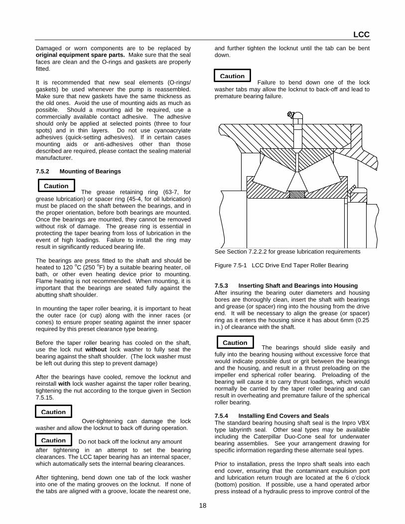
The grease retaining ring (63-7, for grease lubrication) or spacer ring (45-4, for oil lubrication) must be placed on the shaft between the bearings, and in the proper orientation, before both bearings are mounted. Once the bearings are mounted, they cannot be removed without risk of damage. The grease ring is essential in protecting the taper bearing from loss of lubrication in the event of high loadings. Failure to install the ring may result in significantly reduced bearing life. The bearings are press fitted to the shaft and should be heated to 120 oC (250 oF) by a suitable bearing heater, oil bath, or other even heating device prior to mounting. Flame heating is not recommended. When mounting, it is important that the bearings are seated fully against the abutting shaft shoulder. In mounting the taper roller bearing, it is important to heat the outer race (or cup) along with the inner races (or cones) to ensure proper seating against the inner spacer required by this preset clearance type bearing. Before the taper roller bearing has cooled on the shaft, use the lock nut without lock washer to fully seat the bearing against the shaft shoulder. (The lock washer must be left out during this step to prevent damage) After the bearings have cooled, remove the locknut and reinstall with lock washer against the taper roller bearing, tightening the nut according to the torque given in Section 7.5.15.
Over-tightening can damage the lock
washer and allow the locknut to back off during operation. Do not back off the locknut any amount
after tightening in an attempt to set the bearing clearances. The LCC taper bearing has an internal spacer, which automatically sets the internal bearing clearances. After tightening, bend down one tab of the lock washer into one of the mating grooves on the locknut. If none of the tabs are aligned with a groove, locate the nearest one,
and further tighten the locknut until the tab can be bent down.
Failure to bend down one of the lock
washer tabs may allow the locknut to back-off and lead to premature bearing failure.
See Section 7.2.2.2 for grease lubrication requirements Figure 7.5-1 LCC Drive End Taper Roller Bearing 7.5.3 Inserting Shaft and Bearings into Housing After insuring the bearing outer diameters and housing bores are thoroughly clean, insert the shaft with bearings and grease (or spacer) ring into the housing from the drive end. It will be necessary to align the grease (or spacer) ring as it enters the housing since it has about 6mm (0.25 in.) of clearance with the shaft.
The bearings should slide easily and
fully into the bearing housing without excessive force that would indicate possible dust or grit between the bearings and the housing, and result in a thrust preloading on the impeller end spherical roller bearing. Preloading of the bearing will cause it to carry thrust loadings, which would normally be carried by the taper roller bearing and can result in overheating and premature failure of the spherical roller bearing. 7.5.4 Installing End Covers and Seals The standard bearing housing shaft seal is the Inpro VBX type labyrinth seal. Other seal types may be available including the Caterpillar Duo-Cone seal for underwater bearing assemblies. See your arrangement drawing for specific information regarding these alternate seal types. Prior to installation, press the Inpro shaft seals into each end cover, ensuring that the contaminant expulsion port and lubrication return trough are located at the 6 o’clock (bottom) position. If possible, use a hand operated arbor press instead of a hydraulic press to improve control of the

LCC
19
pressing operation. You will be overcoming a light interference fit and may shear off a portion of the outer diameter o-ring, however, this is normal and indicates a secure fit. Slide end covers with gaskets and Inpro seals over the shaft at each end, again making certain that the contaminant expulsion port and lubrication return trough are located at the bottom. Use O-Ring lubricant, Parker O-Lube or Parker Super-O-Lube to lubricate the inner diameter o-rings against the shaft. Take special care when running the seal over the shaft keyway to avoid cutting the o-ring. If necessary, lightly file the keyway edges to avoid this problem. After bolting the end covers in place, rotate the shaft by hand. There should be no frictional contact between the rotating and stationary parts of the Inpro seal. Any rubbing or axial movement in the seal may indicate misalignment. If this is the case, tap lightly into alignment. Note that the drive side end cover clamps against the outer race of the taper roller bearing and may not fit flush against the housing. No shimming is necessary. A gap of up to 1mm (0.04 in.) is acceptable and within the tolerance of the parts. Any larger gap may indicate that the taper roller bearing is not fully seated into the housing. For oil lubrication see Section 7.2.2
Figure 7.5-2 VBX Inpro Seal for LCC
7.5.5 Mounting Shaft Sleeve In mounting the shaft sleeve, do not allow anti-seize compound to come in contact with any of the axial faces of the shaft sleeve, including the impeller contacting face or the face in contact with the shaft shoulder. For ease of removal, a light coating of anti-seize compound should be applied to the inner diameter of the shaft sleeve.
Lubrication at any of shaft sleeve or shaft shoulder faces may result in overloading and breakage of the shaft.
In many cases, there will be an o-ring which must be placed on the shaft first. As the shaft sleeve is pushed into position, this o-ring should be completely forced into the shaft sleeve recess.
If a non-split lantern ring or throat busing is being used, it should be placed onto the shaft sleeve at this time.
Figure 7.5-3 Standard LCC Shaft Sleeve Arrangement 7.5.6 Mounting Stuffing Box 7.5.6.1 Stuffing Box The stuffing box should be mounted so that the sealing water tap is on or near the vertical centerline. This will position the gland studs at 9 o’clock and 3 o’clock for easy access. Note that the small stuffing boxes have a single inlet while the larger sizes have a second port that can be used for additional flow or have a pipe plug installed. Location of the stuffing box is provided by a close clearance fit with the pedestal. No additional centering operation is required. In some cases, a separate stuffing box wear plate may be provided. This should be fastened into place with a fresh gasket. See Figure 4.3-4 for typical stuffing box arrangement. 7.5.6.2 Packing (non-expeller) The packing arrangement consists of a lead ring, followed by a standard lantern ring, and then three more rings of packing (two rings for 70mm shaft).The packing should be well coated with water resistant grease during assembly. See figure 4.3-4. 7.5.6.3 Packing (expeller) As of 2004, the static seal for the expeller has been modified. The forward ring of packing and the standard lantern ring have been replaced with a low flow throat bushing. The throat bushing is followed by a ring of packing, a special lantern ring, and then a second ring of packing.. All rings of packing should be well coated with water resistant grease during assembly. See figure 4.3-5 There is an additional rear tap on the stuffing box for grease lubrication of the packing, allowing the primary (forward) taps to be reserved for intermittent flush water, when needed. When the water purge port is not utilized, a pipe plug should be used to seal the port opening. 7.5.7 Mounting the Bearing Assembly to Pedestal After mounting the stuffing box (or mechanical seal adapter) loosely onto the pedestal plate, and screwing the adjusting screw (909) with nut (924) an appropriate length into the pedestal, the cartridge bearing assembly may be placed onto the pedestal saddle. Note that the slotted tab on the housing must be inserted between the adjusting screw shoulder and the adjusting nut.

LCC
20
Caution The pedestal and bearing housing saddles should be clean, dry, and free from oil or grease. If corrosion of the saddles is a problem, apply a thin film of preservative. Special care must then be taken in the axial adjustment procedure to ensure that no movement may occur. (See the section on Axial Adjustment of Bearing Housing.) The four bearing housing hold down clamps (732) may now be bolted on, but should remain slightly loose until the axial adjustment of the bearing housing is complete. 7.5.8 Metal Expeller Assembly Mounting the expeller casing (10-7) to the pedestal using two spare bolts (not provided) at 180 degrees to each other to hold it temporarily in place. Before mounting the expeller (23-15) two 0.5 mm (0.020 inch) aramid gaskets (400.31) are placed between the shaft sleeve and the expeller to prevent galling and ensure ease of removal. The gaskets should be installed dry, without grease. After mounting the expeller, which is a close sliding fit to the shaft, adjust the bearing assembly towards the drive end until the expeller just begins to rub on the expeller casing. Then move it back towards the pump end approx. 1.0 mm (0.4 inch). This is a preliminary adjustment. Final adjustment will be made after wet end assembly is complete. Mount the expeller plate (16-4) at the same time the shell or casing is mounted by inserting the studs into the shell or casing and allowing the expeller plate to rest on and be supported by the studs.
If attempt is made to mount the expeller plate without the support of the shell or casing studs, it will not be properly supported and may fall without warning. See Figure 4.3-5 for typical expeller arrangement. 7.5.9 Mounting Shell The alignment of the pump shell with the mechanical end is obtained through a rabbet fit machined into the pedestal. For the best wear and efficiency performance, it is essential that the shell be fully seated in this fit.
Ensure that the proper gasket is fitted between the shell and pedestal before installing.
In the case of the elastomer lined LCC-R pump, the liner itself forms the seal. See below for additional instructions. 7.5.10 Elastomer Lined Wet End Firmly seat the liners into the metal casings using a large rubber mallet if necessary. To seat the suction side liner, use a wooden brace and large C-clamps, or lay the liner, flange side up, on a wooden brace and lower the metal casing onto it, allowing the weight of the casing to seat the liner. Seat the elastomer flanges into their grooves using a blunt tool if necessary. The close fit of the liners, although requiring some effort in assembly, will ultimately ensure better liner support, and longer wear life. If desired, liquid soap may be used to lubricate the liners during assembly.
Do not use petroleum-based products to lubricate the liners since they can cause degradation of the elastomer. Before assembling the casing halves together, check the fit of the liners in the casing to ensure that they are seated correctly, especially in the suction, hub, and discharge flange areas. Clearance allowing for limited readjustment of parts has been provided in the holes through which the liner studs protrude. When bolting the casings together, ensure that the liners remain well aligned with each other on their outer perimeter, especially in the discharge area. Some bulge may occur at the seam on the discharge flange. This may be removed, and the sealing surface restored to flatness by lightly buffing with a coarse grade sand paper or grinding stone. If desired, rubber gaskets may be applied at both the suction and discharge flanges, although this is typically not necessary. Some bulging may also occur inside the casing between liners. This is normal and does not affect performance. 7.5.11 Impeller Coat the shaft threads heavily with anti-seize compound. Do not coat the shaft sleeve faces which contact the impeller and the step in the shaft. Two 0.5mm (0.020 inch) aramid gaskets (400.10) are placed between the shaft sleeve and the impeller hub face to prevent galling and to ensure ease of impeller removal. The gaskets should be installed dry, without grease. Screw on the impeller tightly by hand. With larger sizes, it may be convenient to hold the impeller stationary while turning the shaft. Impeller lifting jigs are available to assist in this operation (see Figure 7.4-2). When assembly of the pump is complete, check the impeller to suction wear plate clearance and adjust if necessary, (see section on Axial Adjustment of Bearing Housing). 7.5.12 Suction Plate and Liner ( LCC-H only) Bolt the suction liner to the suction plate and install o-ring before mounting to shell. After mounting, the suction liner should protrude approximately 1.0 mm (0.4 inch) from the suction plate at the suction flange connection. This is normal and provides the sealing surface for the suction piping. 7.5.13 Axial Adjustment of the Bearing Housing In order to maximize the performance and reduce wear, the clearance between the suction face of the impeller and the suction liner must be adjusted to a minimum clearance of 0.25 mm (0.010 in.). This is done by moving the bearing housing assembly with the adjusting screw. Before adjustment may proceed, the pump wet end must be completely assembled. The stuffing box may be packed before or after the adjustment procedure; however, the axial set of any mechanical seal must be left until after adjustment is complete.

LCC
21
Caution
Caution
Bearing Assembly Locknut Assembly Torque 35 mm 100 N-m (75 ft-lbs) 50 mm 135 N-m (100 ft-lbs) 70 mm 200 N-m (150 ft-lbs)
100 mm 375 N-m (275 ft-lbs) 125 mm 680 N-m (500 ft-lbs)
After insuring that the four bearing housing clamps are slightly loosened, run the bearing assembly towards the impeller end by means of the adjusting screw until the impeller first begins to rub the suction liner. It is helpful to slowly rotate the impeller during this procedure. Next, reverse the adjusting screw until the clearance between the impeller and the suction liner is a minimum of 0.25 mm (0.010 in.). Once the clearance is correct, lightly tighten the bolts of the four bearing housing clamps by hand, making sure that proper contact is maintained at all four locations. Next fully tighten the bolts according to the requirements of Section 7.5.15. Finally, firmly lock the adjusting screw and nut together against the bearing housing tab.
Proper tightening of the bearing housing
clamps and adjusting nut is essential to prevent movement of the rotating assembly during operation. Failure to do so can result in severe vibration and damage to all pump components. 7.5.14 Expeller Running Clearance Proper adjustment of the impeller nose clearance as covered in the section Axial Adjustment of the Bearing Housing should result in proper expeller clearances in the new condition and no further adjustments should be necessary. In some cases, however, adjusting the impeller after excessive suction liner wear may result in the expeller rubbing against the expeller plate. In other cases, it is desired to optimize expeller performance rather than optimize the impeller clearance. The following procedure is recommended for optimizing expeller performance or for setting the clearances in pumps containing any worn parts: 1 With the suction plate/liner removed, adjust the bearing assembly toward the pump end until the back surface of the expeller just begins to rub the expeller plate. 2 Mount a dial gauge to indicate cartridge bearing assembly axial movement and zero the dial gauge at this location. 3 Now adjust the bearing assembly toward the drive (or motor) end until the expeller vanes just begin to rub on the expeller casing, or the impeller begins to rub on the hub side of the pump shell, whichever comes first.
4 Adjust the bearing assembly toward the pump end again approximately 1.0 mm (0.04 in.) to provide a minimal expeller running clearance. If optimization of expeller performance is desired, lock the adjustment at this location
Optimizing the expeller clearances is
recommended only in cases where expeller performance is marginal and a small increment in performance is
required to seal against the pump pressure. Setting of clearances for optimal expeller performance may result in excessive impeller clearance and accelerated wear. If necessary, this may be remedied by providing a custom fitted machined spacer with gaskets between the impeller and expeller. 5 Reassemble the suction plate and check the impeller to liner clearance. If not optimizing expeller clearances set the impeller clearance as detailed in the section “Axial Adjustment of the Bearing Housing”. Do not allow the dial gauge to come closer than 1.0 mm (0.04 in.) to the original zero setting or expeller rubbing may occur. If necessary, consider the use of a spacer as mentioned in step 4. 7.5.15 Tightening Torques Taper Bearing Locknut Assembly Torque
Bearing Assembly Clamp Bolts
1) LCC pumps built prior to 1998 may use clamping bolts one size smaller than shown above. If your unit is of this type, reduce the torque values as follows: 35,50mm with M16 bolt: 270 N-m (200 ft-lbs) 70,100,125mm with M20 bolt: 340 N-m (250 ft-lbs) Other Bolts No special torque requirements exist for the remaining LCC nuts and bolts unless specifically called for on the assembly drawing. Bolts and nuts for which torque is not specified should be tightened enough to ensure a firm mating between parts in accordance with good maintenance practice. Where possible, the use of an air driven impact wrench is recommended for bolts over 24mm (1.0 inch) diameter. For additional torque values see section 9.0
7.5.16 Water Purge for Gland Packing The stuffing box is equipped with tapped holes for sealing water. In order to keep the stuffing box free from abrasive particles, the sealing water pressure and gland (452) tightness should be adjusted to maintain a small flow of cool or lukewarm leakage out of the stuffing box. If the leakage becomes hot, the gland should be loosened to allow a greater flow. If cloudiness is seen in the leakage, greater water pressure is needed.
Bearing Assembly
Bolt size Clamp Bolt Torque
35 mm M 20 340 N-m (250 ft-lbs) 50 mm 70 mm
100 mm M 24 680 N-m (500 ft-lbs) 125 mm

LCC
22
Caution
Purge water must be non-aggressive, not liable to form deposits and not containing suspended solids. (Hardness: on average 5; pH > 8, or conditioned and neutral with regard to mechanical corrosion). Inlet temperature tE = 10 to 30o
C (50 to 85 o F) Outlet temperature tA max. 45oC (115 o F) The sealing water pressure required to maintain satisfactory stuffing box operation will vary with pump operating pressure, slurry properties, condition of the packing, and the type of stuffing box. A supply pressure of 10 psi over the discharge pressure of the pump should be available. In most cases, adjustments to supply pressures can be made with a manual valve and gauge near the stuffing box.
The stuffing box purge water should be
pressure controlled, not flow controlled. The amount of flow from the box should be adjusted to the minimum amount required to provide cooling. This often results in flow rates considerably less than those given in the table below, which are maximum requirements for worn packing. Flow control of stuffing boxes is not recommended. It may result in abnormally high sealing pressures and lead to jamming of the packing, excessive heat and wear. Stuffing Box Maximum Seal Water Requirements
For hot, high pressure or otherwise severe service conditions, an optional combination lantern ring / throat bushing is recommended in place the standard lantern ring and first ring of packing. Water requirements for this option will be about mid-way between the forward flush and KE configurations shown in the table above. For expeller applications, the stuffing box used must be of the ‘KE’ (low flow) type with a ring of packing between the lantern ring and pumped fluid. All rings of packing should be well coated with water resistant grease during assembly. 7.6 Spare Parts Stock Due to the erosive action of the slurry, many of the wet end components of the pump may require replacement during normal maintenance. Inspection or overhaul of the mechanical components may also warrant replacement of certain parts. The following are recommended lists of parts to have on hand for normal maintenance and inspection. The quantities of parts kept in store will depend upon the severity of the slurry duty and the number of units
operating. Maintenance practices may also favor keeping fully built sub-assemblies or complete pumps on hand in some cases. Previous experience in similar duties often provides the best experience. If in doubt, contact your GIW / KSB representative for specific recommendations. Wet End Stuffing Box • Casing (or casing liners) • Shaft Sleeve • Impeller • Seal Water Ring • Side Liner • Packing • Gasket Kit • Gasket Kit Bearing Assembly Expeller • Bearings • Casing • Gasket Kit • Plate • Expeller • Gasket Kit 7.6.1 Maintenance Procedures for Maximum Parts Life The wear of slurry pump parts is influenced by many factors and the following procedures are designed to help you get the most out of your wet end wear parts. If problems occur, contact your GIW / KSB representative for a review of your application. Also see section 7.7: “Operational Problems and Solutions”. Suction Liner The suction liner should be rotated 180° at approximately half-life if localized wear occurs. If localized wear is severe, repair as recommended by GIW / KSB before rotation. A new gasket should always be used with a new suction liner or new shell. Impeller The impeller to suction liner clearance should be adjusted forward several times during its life cycle for maximum impeller and suction liner life. See section 7.5.13. In general, an impeller does not require replacement until it fails to produce sufficient head for the application. Impellers are sometimes changed too soon based on appearance. Vibration caused by an impeller wearing out of balance is rare but possible. If this occurs, the impeller may be statically balanced by hand grinding on back shroud. The impeller should never be repaired by welding. Shell If wear is localized with a deep gouge, repair or replace as recommended by GIW / KSB. Excessive wear problems are usually indications that the pump is not operating at the flow and head conditions originally specified for the design. 7.7 Operational Problems and Solutions Many pump wear problems are caused by unstable system operation, or off duty pump operation. Although the dynamics of slurry piping systems cannot be fully addressed in this manual, the following items should be considered. Also refer to section 8: “Trouble Shooting”
Nominal Stuffing Box Type Shaft Size
Standard KE
Forward Flush (Non-Standard)
Throat Bushing
35mm 0.09 l/s (1.4 gpm)
0.44 l/s (7 gpm)
0.18 l/s (2.8 gpm)
50mm 0.11 l/s (1.7 gpm)
0.54l/s (8.5 gpm)
0.21 l/s (3.4 gpm)
70mm 0.15 l/s (2.4 gpm)
0.76 l/s (12 gpm)
0.30 l/s (4.8 gpm)
100mm 0.20 l/s (3.1 gpm)
0.98 l/s (15.5 gpm)
0.39 l/s (6.2 gpm)
125mm 0.23 l/s (3.7 gpm)
1.17 l/s (18.5 gpm)
0.47 l/s (7.4 gpm)

LCC
23
Sump Design A minimum sump capacity of one minute at the expected flow conditions should be provided. Sump design should prevent any uneven flow of the solids to the suction. Often, a flat bottom sump is best since it will allow the solids to assume a natural slope of repose. The sump should be observed during operation to insure that solids are not building up and sloughing off. Sump design should prevent the formation of a vortex, or other means of introducing air into the pump. Where a submerged suction is available, the depth of water level above the pump suction is more important than the cross-sectional area of the sump. Frothing of the sump should be eliminated by the installation of baffles, a submerged inlet pipe or other methods to prevent air becoming entrained in the slurry. If unavoidable, frothing must be accounted for in the system design and operation. If the sump runs dry, the system will surge causing accelerated pump wear. Pump speed or impeller diameter should be decreased or make up water increased. If the flow variations are too great, a variable speed motor may be required. Cavitation / NPSH Performance The NPSH available must always be greater than the NPSH required by the pump or cavitation will occur resulting in head loss (drop in discharge pressure), increased wear rate of the pump parts, and shock loading of the pump bearing assembly. If any conditions occur, consult your GIW / KSB representative for the NPSH requirements of your pump. To maximize the NPSH available to the pump, insure that the suction line is as short and straight as possible and the sump level is as high as possible, (or the suction lift as small as possible in the case of a pump located above the water level). Minimizing the number of valves or short radius fittings and attaching a suction inlet bell will also reduce entrance losses. A larger diameter suction pipe may help, but one must be careful not to reduce the flow velocity below safe carrying levels or bedding of the slurry will occur and result in increased suction liner and impeller wear. In dredging applications where a free suction pipe or suction cutter head is lowered into the solids to be pumped, it is useful to have pressure gauges attached to the pump suction and discharge. An operator, by observing the gauges, will be able to maintain a maximum suction vacuum without cavitating the pump. Piping System Design With coarse settling slurries, the pipelines should be vertical or horizontal. Inclined pipelines may surge due to a backward drift or build up of solids. Also, an increase in slurry friction loss may be experienced in these sloped lines, further reducing performance. Piping diameters must be properly sized to maintain sufficient carrying velocity. Oversized pipelines may result in the formation of a sliding bed of slurry, which can greatly accelerate the wear of pumps and pipelines.
Operating Conditions of Flow and Head It should be noted that the pump always operates at the intersection of the pump curve and the pipeline "system" curve. During the initial stages of operation, motor load on the pump should be checked. If there is an excess amount of power being drawn by the pump, it may be caused by the system head (TDH) being lower than predicted thus resulting in higher flow rates and power consumption. This sometimes happens when a safety factor is applied to the head during the design of the system. Cavitation may also occur under these high flow conditions. The pump speed should be slowed down to reduce flow, or the total discharge head against the pump should be increased (resulting in reduced flow and power consumption). If actual supply flow rates are lower than predicted, the sump may run dry causing the system to surge and accelerating pump wear. Pump speed or impeller diameter should be decreased or make up water increased to keep the sump at the highest stable level possible. If the flow variations are too great, a variable speed motor may be required. This problem is especially common in applications with a high proportion of static head, such as mill discharge and cyclone feed. It can be further aggravated by operation well below the best efficiency flow rate of the pump where the pump head curve is relatively flat. Under these conditions, minor fluctuations in the system resistance caused by normal variations in solids concentration or size can result in surging flow rates. Whenever possible, avoid prolonged operation at flows well below the optimum flow rate. This causes recirculation of slurry within the pump and encourages localized wear. In the event problems are encountered, contact your GIW / KSB representative. The pump serial number, in addition to the following, should be furnished to assist in evaluation of the problem: A. Pump serial number (from the nameplate on the
pedestal), customer location, and the approximate startup date.
B. Pumped fluid SG (specific gravity), slurry information
including SG and particle size, and liquid temperature. C. The approximate flow rate desired, and the actual
minimum and maximum flow rate of the system if known.
D. The system static head (the difference in elevation
between the water level on the suction side of the pump and the point of discharge)
E. The length and size of suction and discharge lines,
including a description of the general arrangement including fittings, bends and valves
F. If the discharge point is not to atmosphere, what is the
pressure, (e.g. cyclone backpressure).

LCC
24
G. If suction is taken from a sump, provide the general arrangement including size dimensions and minimum and maximum sump levels referenced to the suction centerline of the pump.
H. The available driver horsepower, speed of motor and
pump or description of the ratio device between the pump and motor.
I. The impeller diameter if different from that supplied
with the pump. The above items of data are especially important when a pump has been transferred from the duty for which it was selected to some other application. In many instances, it will be found that unusual wear in the pump, or low efficiencies, are caused by a mismatch between the pump and the system application and can be corrected once the operating conditions are known. Contact your GIW / KSB representative for further specific recommendations regarding system design. A useful reference and textbook has also been published by GIW titled: “Slurry Transport Using Centrifugal Pumps,” by Wilson, Addie & Clift. 8 Trouble Shooting 8.1 Low Flow Rate a) Verify that the pump is correct for the system
parameters in terms of flow and head. The pump curve can be used to determine the output, power and speed.
b) Depending on the age and service of the pump, parts could be worn sufficiently to reduce performance.
c) Verify that the motor has the correct power and voltage required for the system, and is operating properly.
d) Verify that the pump is running at the correct speed. e) Verify that the suction side has adequate NPSH (Net
Positive Suction Head) as outlined in the pump specifications.
f) Check the suction pipe for air pockets, leaks, partially closed valves or other restrictions.
g) Be certain that the suction inlet and impeller are not clogged.
h) Verify that the discharge valve is fully open. 8.2 Bearing Temperature a) During the initial break in period, the bearings will
normally run hotter as explained in the Initial Start Up section.
b) Excess temperature may be due hot process fluid c) Verify correct oil level. Overfilling causes viscous
drag, which builds heat. d) Verify oil viscosity. High viscosity and mineral oils
cause drag and build heat, especially at higher speeds.
e) Misalignment of the motor or coupling can create excess bearing load and increased heat.
f) Insufficient coupling clearance between the pump shaft and motor shaft can add axial loads to the thrust bearings.
g) External pipe forces can distort the pump and bind the bearings.
h) Worn or damaged bearings may generate excess heat before failure.
i) Drag from external parts such as coupling guards. 8.3 Bearing Contamination a) Excess leakage at stuffing box b) Damaged Inpro bearing isolator c) Improper maintenance d) Wrong lubricant e) End cover seal damaged or missing 8.4 Stuffing Box See the Packing section for procedures. a) High temperature due to packing adjusted too tight. b) High temperature due hot process fluid. c) Leaking caused by excess flush pressure. d) Leaking caused by wrong adjustment. e) Leaking caused by worn parts. f) Excess wear of packing or sleeve: 1. Adjusting the packing too tight. 2. Insufficient flush flow or pressure. 3. Contaminated flush water. 4. Poor quality packing 5. Failure to lubricate new packing 8.5 Overheating of Pump Casing See Piping Connection section for details. a) Hot process fluid being pumped b) Prolonged running against shut head or blocked
discharge. NOTE: This is could create a Dangerous condition!!
c) Blocked suction d) NPSH too low for pump. e) Air pockets in suction pipe or pump. 8.6 Pump Leaking a) Defective gasket at pump flange. b) Defective seal between pump casing, liner or housing. c) Casing or liner worn through. d) Normal or excess stuffing box flow 8.7 Motor Overload a) Verify that the motor has the correct power and
voltage supply, and is operating properly. b) Verify that the motor is correct for the pump. The
pump specifications and curve can be used to determine the power and speed required
c) Verify that the pumped fluid matches the system design viscosity and specific gravity.
d) Coupling misaligned. e) Gland adjusted too tight. f) External pipe forces can distort the pump and bind the
motor and pump bearings. g) Drag from external parts such as guards . 8.8 Vibrations or Abnormal Noises a) Cavitation due to low NPSH or blocked suction. b) Impeller rubbing due to incorrect nose adjustment. c) Out of balance impeller. d) Debris jammed in impeller vanes. e) Pump or motor mounting bolts loose f) Air in system.

LCC
25
g) Large solids in pumped fluid. h) Coupling misaligned. i) Belts misaligned or incorrectly tightened. j) Insufficient clearance between the pump shaft and
motor shaft at coupling. k) Worn bearings in pump or motor. l) Gland adjusted too tight. m) Vibrations from system transmitted through piping. n) Damaged or bent shaft in pump or motor.

LCC
26
9 Torque Values for Metric Fasteners not otherwise Specified
Tightening Torque Values Class 8.8 Metric Hex Head Capscrews
Metric Coarse & Fine Thread
Dry (reference only) Oil or Thread Lock Anti-Seize Thread Size in-lbs ft-lbs Ncm Nm in-lbs ft-lbs Ncm Nm in-lbs ft-lbs Ncm Nm
M4 X 0.7 28 316 21 236 17 190
M5 X 0.8 57 644 42 480 34 386
M6 X 1 95 1074 71 800 57 644
M8 X 1.25 228 2576 170 1919 137 1546
M8 X 1 239
2701
178
2012
143
1620
M10 X 1.5 468 38 5288 52 349 28 3940 38 281 23 3173 31
M10 X 1.25 38 52 28 38 23 31
M12 X 1.75 67 91 50 68 40 55
M12 X 1.25 70 95 52 71 42 57
M14 X 2 105 142 78 106 63 85
M14 X 1.5 111 150 83 112 67 90
M16 X 2 158 214 118 160 95 129
M16 X 1.5 166 225 124 168 100 135
M20 X 2.5 317 430 236 320 190 258
M20 X 1.5 339 460 253 342 203 276
M24 X 3 548 743 408 554 329 446
M24 X 2 575 780 428 581 345 468
M30 X 3.5 1098 1489 818 1109 659 893

LCC
27
NOTES

LCC
28
10 General Drawing with List of Components
Pump assembly, bill of material and other drawing or special instructions relevant to each order will be attached to the back of this manual.10 11 Supplements Supplements provide additional information for optional equipment. These options may not be available for your pump. See your Bill of Materials for options that were included with your pump. 11. 1 Stuffing Box Throat Bushing Option See page 28 11.2 Underwater Pump Operation with Duo-Cone Bearing Seals See page 29 11. 3 Duo-Cone Seal See pages 30-31 11. 4 Diverter See page 32
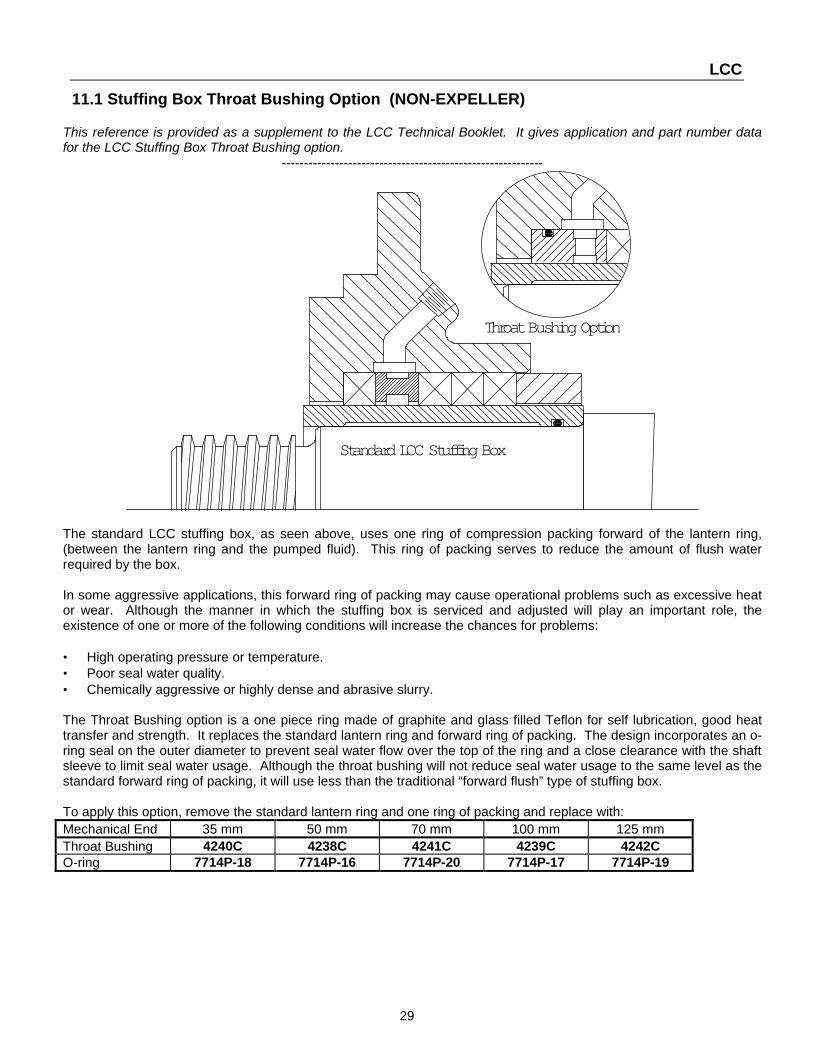
LCC
29
11.1 Stuffing Box Throat Bushing Option (NON-EXPELLER)
This reference is provided as a supplement to the LCC Technical Booklet. It gives application and part number data for the LCC Stuffing Box Throat Bushing option.
-----------------------------------------------------------
Throat Bushing Option
Standard LCC Stuffing Box
The standard LCC stuffing box, as seen above, uses one ring of compression packing forward of the lantern ring, (between the lantern ring and the pumped fluid). This ring of packing serves to reduce the amount of flush water required by the box. In some aggressive applications, this forward ring of packing may cause operational problems such as excessive heat or wear. Although the manner in which the stuffing box is serviced and adjusted will play an important role, the existence of one or more of the following conditions will increase the chances for problems: • High operating pressure or temperature. • Poor seal water quality. • Chemically aggressive or highly dense and abrasive slurry. The Throat Bushing option is a one piece ring made of graphite and glass filled Teflon for self lubrication, good heat transfer and strength. It replaces the standard lantern ring and forward ring of packing. The design incorporates an o-ring seal on the outer diameter to prevent seal water flow over the top of the ring and a close clearance with the shaft sleeve to limit seal water usage. Although the throat bushing will not reduce seal water usage to the same level as the standard forward ring of packing, it will use less than the traditional “forward flush” type of stuffing box. To apply this option, remove the standard lantern ring and one ring of packing and replace with: Mechanical End 35 mm 50 mm 70 mm 100 mm 125 mm Throat Bushing 4240C 4238C 4241C 4239C 4242C O-ring 7714P-18 7714P-16 7714P-20 7714P-17 7714P-19

LCC
30
11.2 Underwater Pump Operation with Duo-Cone Bearing Seals The Underwater Cartridge Bearing Assembly (UCBA) uses Duo-Cone seals in the end cover. Sealing is accomplished with two hardened, precision ground faces running against each other. An elastomer toric applies pressure to the faces and allows the seal rings to accommodate axial and radial run out. The contact pressure and shaft speed will generate heat in the seal faces that must be removed by the surrounding water as the pump is running. Correct installation and adjustment is extremely critical to the proper function and life of these seals. Due to the angular position of ladder mounted pumps in most dredge operations, the UCBA must be completely filled with oil to provide lubrication to the rear thrust bearing when the cutter head is lowered. This requires the use of tank mounted above the deck to detect leaks and accommodate internal pressure changes. A pressurized recirculating system can be used, but the simplest method is an expansion tank suitable for operation within the marine environment. This must be designed to prevent dirt, water or other contaminants from entering the oil system while providing a vent to atmosphere. This tank keeps a positive pressure on the bearing side of the Duo-Cone seals to counteract the water pressure as the pump is submerged. The tank should be mounted high enough to maintain a pressure of about 7 psi (0.5 bar) above what is created by the maximum water depth. Note that the specific gravity of oil is only about 85% of water and must be taken into account when calculating the mounting height of the tank. The tank should have an oil level indicator to allow the operator to see if the level changes. After the oil temperature stabilizes, the level should remain constant and any significant change would indicate a leaking seal. This early warning can prevent oil from leaking into the surrounding water and avoid bearing failure. Dredge pumps are designed to run with the UCBA and Duo-Cone seals fully submerged. This enables the surrounding water to dissipate heat generated by the bearings and seal faces. If the pump will be operated above the water line for extended periods, the bearings can create extra heat in the oil and the seal faces may overheat. Provisions should be made to provide a supply of cooling water to each Duo-Cone seal and a water spray onto the UCBA itself. If the pump will run continuously above water, other sealing systems are recommended, or oil circulating and seal cooling systems will be required. Care should be taken to operate the pump within the speed limitations specified by GIW on the pump drawing for the particular seal size installed. If a seal is replaced, it must be installed with the correct gap (specified by GIW for each seal size) between the seal holders, as this distance provides the correct seal face pressure for proper operation. Failure to operate the seals within the above parameters may result in premature seal failure or oil leakage through the Duo-Cone seals. Any change in the operating conditions should be discussed with your GIW / KSB representative to establish if the new conditions are suitable for the equipment.
Isopropyl Alcohol
Lube for Seal Faces

LCC
31
11.3 Duo-Cone Seals
Seal rings, rubber torics and housings must be completely clean and free of any oil or dirt. Use a lint free cloth with a solvent that evaporates quickly and leaves no residue. It must be compatible with rubber toric rings. Isopropyl Alcohol or other mild cleaner will work. Follow all safety guidelines for use according to the solvent Material Safety Data Sheet. Check the rubber toric for surface defects and inspect the entire metal seal face for dirt or marks. Do not place the
polished seal ring face on any surface. Gently stretch the toric over the metal seal rings until it seats in the radius. Verify that the toric is not twisted by inspecting the mold flash line on the outside diameter. Eliminate any irregularity by gently pulling a section of the toric radially off the ring and letting it snap back. Twisted torics will cause nonuniform face load, resulting in leakage and bearing contamination.
Place the housing end cover and seal holder on a flat, clean surface. Verify that the grooves are clean and free from burrs or sharp edges. Using the correct Seal Installation Tool, locate the machined ridge in the tool over the toric and clamp together. Align the parts squarely with the groove and carefully snap the seal assembly into place using a rapid, even push. Isopropyl alcohol can be used as a lubricant. Allow time for the assembly lube to evaporate.
Apply a very thin film of pure Molybdenum Disulfide lubricant or light oil to the seal faces just prior to final assembly. This will lubricate the seals during initial start up. Do not to get any lube on the rubber toric rings. Be sure there is no debris on either of the seal faces, since even a small piece of lint can hold the seal faces apart and cause leakage or damage to the sealing surfaces.
Rubber Toric
Metal Seal Ring

LCC
32
Final assembly is detailed on the Bearing Housing Assembly drawing. Bolt the end covers in place and install the two (2) studs and nuts for the installation tool. Verify that there are no burrs or sharp edges on the shaft that could damage the o-ring. Coat the long set screws with anti-seize and thread them into the tapped holes until the points are 1/8” (3mm) from the inside bore. Install the o-ring in the Seal Holder. Coat the ID of the holder with RTV silicone sealant, including the o-ring and set screw holes. Place a small bead of silicone around the shaft diameter to help the o-ring slide. Use extra care at the shaft keyway. Place the gap spacer over the shaft and carefully slide the holder until it contacts the spacer. Drop the installation tool over the shaft and tighten the nuts ¼ to ½ turn past Hand Tight against the tool. The gap spacer should not move and the holder should contact it evenly on all sides. Tighten the set screws in a crisscross pattern. Remove the installation tool and gap spacer, and then retorque the set screws. Coat the lock screws with anti-seize and tighten them in the tapped holes. Fill the tapped holes flush to the top with silicone to protect the set screws. This will make removal easier for future maintenance. Rotate the shaft by hand and check for smooth operation. Verify that the holders are square to the end cover. The metal seal rings may appear cocked slightly relative to the holders. This is not a problem, the rings will run true when the pump starts. After the assembly is complete, remove one of the pipe plugs from the bearing housing. Install an air line fitting and slowly pressurize the unit with dry shop air to 10-15 psi or 1 bar. Check all joints and the Duo-Cone seals for leaks by spraying with a soapy water solution. Do NOT exceed 15 psi, as this could cause the torics to extrude from the seal grooves. If this occurs, disassemble the unit and reinstall the toric. Release the air pressure, replace the pipe plug and prepare the unit for shipping or installation on the pump pedestal. Units being returned to service must be completely filled with oil. Remove the top filler plug and add oil. If the unit will remain empty during pump installation, be sure it is clearly indicated to ADD OIL prior to start up on both the pump and the control panel. After the day tank is connected, fill the hoses and tank. Allow time for the oil to displace the air in the lines. Mark the oil level in the tank for reference. Note that a single hose system or colder temperatures will require time to bleed all the air from the system. The level should equalize after the pump has been operating for an hour or two. At this point, fill the tank to the correct operating level.

LCC
33
11.4 Diverter
One of the product improvements to the GIW LCC Expeller pumps is the addition of a Diverter to further reduce the accumulation of solids in the expeller chamber. This is a urethane part that is pressed into the hub area of the pump casing. See the LCC Maintenance Manual for specific pump disassembly procedures.
Installation instructions: Disable the driver to prevent pump operation
Drain the system and remove the suction pipe
Remove the suction liner and impeller
Clean the hub area of the pump casing
Removal of the pump casing will be necessary for the LCC 9 Metal & Rubber lined pumps, see figure below.
Clean the face of the expeller hub
Position the Diverter with the tapered ring facing into the pump as shown below
Press the Diverter completely back against the expeller plate –
If necessary, seat the Diverter using a small hammer and a smooth wood block cut to fit between the lip and casing
Place a small straight edge along the back of the pump casing to verify the diverter is flush to the casing plane within 3 mm.
Place two (2) new impeller release gaskets on the shaft
Coat the shaft threads with anti-seize
Thread the impeller on the shaft and hand tighten
Reinstall the suction liner and adjust the impeller nose gap
Connect the suction piping and restart the pump