lbw50 manual 02 12 2010 booklet - cool air incorporated...
TRANSCRIPT

1544 134th Avenue NE, Ham Lake, MN 55304 USA
Phone (763) 205-0844 Fax (763) 432-9295
iinnffoo@@ccoooollaaiirriinncc..ccoomm
wwwwww..ccoooollaaiirriinncc..ccoomm

CAUTION & SYMBOL DEFINITIONS:
CAUTION: Gives detailed description of different situations to
avoid or not avoid for the proper operation of the
equipment.
WARNING: RISK OF ELECTRIC SHOCK. DO NOT
REMOVE COVER. NO USER SERVICEABLE
PARTS INSIDE. REFER TO QUALIFIED SERVICE
PERSONNEL.
AVIS: RISQUE DE CHOC ELECTRIQUE. NE PAS
ENLEVER LE COUVERCLE. AUCUN ENTRETIEN
DE PIECES INTERIEURES PAR L'USAGER.
CONFIER L'ENTRETIEN AU PERSONNEL
QUALIFIE.
LBW-50 Ammonia Leak Detector
Page 30 Rev. 2 1/08/10
Copyright © 2010 by Cool Air Incorporated. All rights reserved.
LLBBWW--5500 SSPPEECCIIFFIICCAATTIIOONNSS ((ccoonntt’’dd))
Pollution Degree 1
Approvals
Tested to UL 61010-1:2004 R7.05
CAN/CSA-C22.2 61010-1:2004
By TUV
Certificate no. Pending
Options
1. Remote ammonia sensor with box and cable
(500 ft. max.)
2. Back-up battery
3. Stainless-steel washdown tube
4. Remote alarm light and horn unit with box,
cable, & TEST/NORMAL/SILENCE
toggle switch.

LBW-50 Ammonia Leak Detector
Page 2 Rev. 2 1/08/10
Copyright © 2010 by Cool Air Incorporated. All rights reserved.
TTAABBLLEE OOFF CCOONNTTEENNTTSS
IIMMPPOORRTTAANNTT——RREEAADD TTHHIISS FFIIRRSSTT ........................................................ 4
CAUTIONS…………………………………………………………………44 AVOIDING NUISANCE ALARMS………………………………....………………………………………………..……44
IINNTTRROODDUUCCTTIIOONN........................................................................................ 5
SSTTAANNDDAARRDD FFEEAATTUURREESS ........................................................................... 5
AAVVAAIILLAABBLLEE OOPPTTIIOONNSS ............................................................................. 6
PPAARRTTSS DDEESSCCRRIIPPTTIIOONN .............................................................................. 7
FRONT PANEL DISPLAY………………………………………………..77 AMMONIA SENSOR…………………………………………………………..88 FRONT PANEL-MOUNTED CIRCUIT BOARD……....88 SERVICE SWITCH (SERVICE MODE)……………………....99 ADJUSTABLE ALARM POTENTIOMETER…………......99 LED TEST BUTTON…………………………………………………………99 LOCAL/REMOTE JUMPERS…………………………………………99 RELAY LED’S……………………………………………………………………99 ENCLOSURE-MOUNTED COMPONENTS…………....1111 RELAYS………………………………………………………………………………1122 RELAY STATUS LED’S………………………………………………1122 EXTERNAL CONNECTIONS……………………………………....1122
WIRING DIAGRAMS……………………………………………………..1133
TTyyppiiccaall 115 VAC Application……………...14
TTyyppiiccaall 230 VAC Application……………...15
TTyyppiiccaall 16 VAC or 24 VDC Application…..16
IINNSSTTAALLLLAATTIIOONN AANNDD SSEETTUUPP................................................................ 17
EEXXAAMMPPLLEE AAPPPPLLIICCAATTIIOONN ....………………………………………………………………............................1188--1199
REMOTE SENSING...………………………………............................... 20
REMOTE ALARM……….…………………………................................21
BACKUP BATTERY……..…………………………...............................22
LBW-50 Ammonia Leak Detector
Page 29 Rev. 2 1/08/10
Copyright © 2010 by Cool Air Incorporated. All rights reserved.
LLBBWW--5500 SSPPEECCIIFFIICCAATTIIOONNSS
Ammonia Detection
Sensitivity 25 to 800 PPM
Ammonia Sensor
Metal oxide semiconductor
833 mW integral heater
Alumina ceramic base
100 mesh SUS 316 double gauge flame
arrestor
Relays
Alarm, Pre-Alarm, and Auxiliary
(auxiliary relay operates at same time
as alarm relay)
Form C (SPDT), normally-open,
normally-closed, energized in
normally-open state.
Rated 5A, 115 VAC or 24 VDC
Outputs
Contacts for: alarm, pre-alarm, and
auxiliary relays, and external
temperature sensor
Operating Temperature -50°F to 125°F
Operating Humidity 5% to 95% RH, non-condensing
Power Requirements
115/230 VAC, 60 Hz, 0.12 Amps max.
or 24 VDC , 0.58 Amps max.
or 16VAC, 0.65 Amps max.
Dimensions: 7-1⁄2"H x 7-1⁄2"W x 4-1⁄2"D
Weight: 4 lbs.
Enclosure: NEMA 4X rated, UL listed, CSA, IEC,
IP66

LBW-50 Ammonia Leak Detector
Page 3 Rev. 2 1/08/10
Copyright © 2010 by Cool Air Incorporated. All rights reserved.
TTAABBLLEE OOFF CCOONNTTEENNTTSS ((CCoonntt..))
TTEESSTTIINNGG AANNDD CCAALLIIBBRRAATTIIOONN........................................................ 24-25
TTEECCHHNNIICCAALL SSUUPPPPOORRTT .......................................................................... 26
WWAARRRRAANNTTYY.............................................................................................. 27
LLBBWW--5500 SSPPEECCIIFFIICCAATTIIOONNSS ............................................................... 28-29
LBW-50 Ammonia Leak Detector
Page 28 Rev. 2 1/08/10
Copyright © 2010 by Cool Air Incorporated. All rights reserved.
WWAARRRRAANNTTYY
The LBW-50 comes with a 36-month limited warranty from the time of purchase.
Cool Air Incorporated guarantees that the LBW-50 ammonia leak detector,
when connected to and operated in accordance with the instructions
contained in this manual, will perform in accordance with the warranty
expressed on the cover of the detector. Not installing, maintaining,
repairing, or operating the detector in accordance with the instructions in this
manual will automatically void the warranty.
Cool Air Incorporated will not be held liable for any losses, liabilities,
judgments, attorney fees, claims, or damages, including incidental and
consequential damages.
THE DETECTOR MUST BE TESTED AT LEAST ONCE A MONTH
AND CALIBRATED AT LEAST ONCE A YEAR TO ENSURE IT IS
OPERATING ACCURATELY AND CORRECTLY. TEST AND
CALIBRATION RECORDS MUST BE RECORDED ON
APPROPRIATE LOG SHEETS.

LBW-50 Ammonia Leak Detector
Page 4 Rev. 2 1/08/10
Copyright © 2010 by Cool Air Incorporated. All rights reserved.
IIMMPPOORRTTAANNTT——RREEAADD TTHHIISS FFIIRRSSTT
PPLLEEAASSEE RREEAADD AANNDD UUNNDDEERRSSTTAANNDD TTHHIISS SSEECCTTIIOONN BBEEFFOORREE
IINNSSTTAALLLLIINNGG AANNDD OOPPEERRAATTIINNGG TTHHEE LLBBWW--5500 DDEETTEECCTTOORR
CCAAUUTTIIOONN::
Operating the detector in lower temperatures will slow the detector response
rate, and high humidity or excessive heat can cause the “Minimal
Concentration” LED to light.
After applying power, test the detector to ensure it is operating correctly. Be
sure the detector has been powered for at least 8 hours before testing.
Adequately cover the detector sensor during washdown, and avoid spraying
the washdown liquid directly onto the sensor.
AAvvooiiddiinngg NNuuiissaannccee AAllaarrmmss
To avoid nuisance alarms, place the detector in service mode before:
• Adjusting the Alarm setpoint.
• Performing maintenance, repairs, testing, or calibration.
• Performing maintenance on nearby compressor systems.
• Painting and/or cleaning nearby.
• Performing refrigeration system maintenance.
• Washing down the area.
• Removing the ammonia sensor.
Furthermore, be sure of the following before placing the detector in normal
operating mode:
• The ammonia concentration reading is below the Alarm setpoint.

LBW-50 Ammonia Leak Detector
Page 5 Rev. 2 1/08/10
Copyright © 2010 by Cool Air Incorporated. All rights reserved.
IINNTTRROODDUUCCTTIIOONN
The Cool Air Incorporated LBW-50 is an AC/DC powered state-of-the-art
ammonia leak detector that detects and displays ammonia concentrations of
25 to 800 parts per million (PPM). It comes equipped with a solid-state,
long-life ammonia sensor that has a quick and accurate response to ammonia
concentrations.
SSTTAANNDDAARRDD FFEEAATTUURREESS
The LBW-50 comes with these additional standard features:
• Adjustable Alarm setpoint..
• Normally-open, normally-closed contacts for communicating with
common industry alarm systems.
• A NEMA 4X, UL-listed enclosure.
• Spare contacts for operating auxiliary equipment such as exhaust
fans, king valves, compressors, and additional alarm systems.
• Service mode which allows for testing and calibrating without
setting off the alarms.

LBW-50 Ammonia Leak Detector
Page 6 Rev. 2 1/08/10
Copyright © 2010 by Cool Air Incorporated. All rights reserved.
AAVVAAIILLAABBLLEE OOPPTTIIOONNSS
In addition to the standard features, the LBW-50 can be equipped with these
options:
• A remote ammonia sensor with cable allowing the sensor to be
located a maximum of 500 feet away from the detector.
• An internal back-up battery to keep the detector working during
loss of main power.
• A stainless-steel washdown tube installed over the sensor to
minimize the chance of getting wet during washdown.
• A remote alarm light and horn box with a toggle switch to
TEST/NORMAL/SILENCE the alarm.
Contact Cool Air Incorporated technical support for more detailed
information, or for purchasing, any of these options.

LBW-50 Ammonia Leak Detector
Page 7 Rev. 2 1/08/10
Copyright © 2010 by Cool Air Incorporated. All rights reserved.
PPAARRTTSS DDEESSCCRRIIPPTTIIOONN
FFrroonntt PPaanneell DDiissppllaayy
The front panel display is comprised of a series of labeled indicating LED’s.
The LED’s provide an indication of ammonia concentration, alarm status,
power supply, and service mode at a glance.
For information on how the display indicates ammonia concentrations, see
the sections on ammonia leak indication
.

LBW-50 Ammonia Leak Detector
Page 8 Rev. 2 1/08/10
Copyright © 2010 by Cool Air Incorporated. All rights reserved.
AAmmmmoonniiaa SSeennssoorr
The detector comes with a solid-state, long-life sensor that has a high
sensitivity to amine compounds and a quick response to concentrations of
ammonia. The sensor is protected by a flame arrestor, and has an integral
heater and a ceramic base that is resistant to severe environments.
If a new ammonia sensor is installed, the detector must be re-calibrated. See
the “TESTING AND CALIBRATION” section starting on pages 24-25.
FFrroonntt PPaanneell--MMoouunntteedd CCiirrccuuiitt BBooaarrdd
The front panel-mounted circuit board (see picture on page 9) contains the
controls necessary for adjusting and operating the detector. Each control is
described in detail in the following pages. When the detector enclosure is
open, this circuit board is on the left, attached to the front panel.
LBW-50 Ammonia Leak Detector
Page 23 Rev. 2 1/08/10
Copyright © 2010 by Cool Air Incorporated. All rights reserved.
AAmmmmoonniiaa LLeeaakk IInnddiiccaattiioonn
In the event of a higher-than-normal ammonia concentration, the front-panel
LEDs will indicate as follows:
If the Ammonia
Concentration… Then the… And…
Equals or exceeds
25 PPM
Red “Minimal
Concentration” LED lights
No other actions
occur
Equals or exceeds
the pre-alarm set
point
Yellow “Early Warning”
LED lights
The pre-alarm
relay trips
Continues to
increase above the
pre-alarm set point
First red “Progressive”
LED lights
No other actions
occur
Equals or exceeds
the alarm set point Red “Alarm” LED flashes
The alarm and
auxiliary relays
trip
After an alarm, the alarm and auxiliary relays will automatically reset when
the ammonia concentration falls below the alarm set point, and the pre-alarm
relay will automatically reset when the ammonia concentration falls below
the pre-alarm set point.
◄
INC
RE
AS
ING
◄
CO
NC
EN
TR
AT
ION
◄

LBW-50 Ammonia Leak Detector
Page 9 Rev. 2 1/08/10
Copyright © 2010 by Cool Air Incorporated. All rights reserved.
SSeerrvviiccee SSwwiittcchh ((SSeerrvviiccee MMooddee))
The detector can be set to one of two modes: normal operating mode or
service mode. The detector is in normal operating mode when the service
LBW-50 Ammonia Leak Detector
Page 22 Rev. 2 1/08/10
Copyright © 2010 by Cool Air Incorporated. All rights reserved.
Backup Battery Testing, Installation and Replacement
The LBW50 can be supplied with an optional Backup Battery from Cool Air
Incorporated. This backup supply is good for approximately 1 ½ hours of
operating time. During normal operation, the backup battery is not used but
is kept trickle charged. In the event of a power failure, the unit will
seamlessly operate off of the back-up battery.
WARNING: RISK OF ELECTRIC SHOCK. DO NOT
REMOVE COVER. NO USER SERVICEABLE
PARTS INSIDE. REFER TO QUALIFIED SERVICE
PERSONNEL.
AVIS: RISQUE DE CHOC ELECTRIQUE. NE PAS
ENLEVER LE COUVERCLE. AUCUN ENTRETIEN
DE PIECES INTERIEURES PAR L'USAGER.
CONFIER L'ENTRETIEN AU PERSONNEL
QUALIFIE.
To test an existing or new battery installation, simple disconnect the leak
detector power supply. The unit should stay in normal operation and not
turn off. If the unit turns off, check to make sure that the red and black wires
are secure on the battery terminals and the circuit board terminals. If the
wiring is good, the battery should to be replaced.
If the back-up battery needs to be replaced because it has either failed, or
will not keep a charge, a new back-up battery can be ordered through your
local leak detector supplier or directly from Cool Air Incorporated. Prior to
removing the old battery, disconnect the leak detector power supply, remove
the black and red wires from the battery terminals, cut the wire cable strap
(used primarily for shipping), and remove the battery from the Velcro
mounting pad. Install the new battery onto the Velcro mount pad, remove
the battery protector caps, plug the black wire into the black terminal, plug
the red wire to the red terminal, and reconnect the leak detector power
supply. Allow 24-hours of leak detector operation time before testing the
new battery.

LBW-50 Ammonia Leak Detector
Page 10 Rev. 2 1/08/10
Copyright © 2010 by Cool Air Incorporated. All rights reserved.
switch is in the “Normal” position. When the service switch is in the
“Service” position, the detector continues to function as usual, however the
alarm, pre-alarm, and auxiliary relays are disabled. This allows the detector
to be serviced, tested, and calibrated without tripping the alarm relays and
setting off the alarms.
When the detector is in the service mode, the “Service” LED on the front
panel flashes yellow. After 30 minutes in service mode, the “Minimal
Contamination” and “Early Warning” LEDs will also be lit. This is done as
a reminder to set the service switch back to the “Normal” mode. .
AAddjjuussttmmeennttaabbllee AAllaarrmm PPootteennttiioommeetteerr
There is one adjustment potentiometer that is provided to set the Alarm
setpoint. The Pre-Alarm (Early Warning) is adjusted at the factory and
‘locked’ into place. The Alarm setpoint is also pre-set at the factory but is
field adjustable. The adjustment procedure is in the “INSTALLATION
AND SET-UP” section, on page 17.
LLEEDD TTeesstt BBuuttttoonn
Pressing the momentary LED Test button will cause all LED’s to light to up
and all three relays to de-energize to confirm that they are functional.
LLooccaall//RReemmoottee JJuummppeerrss
JMPR1 and JMPR2 convert from a local (enclosure mounted) sensor to a
remote sensor. For a local sensor, both jumpers must connect pins 1 to 2, the
far right position when viewed as shown in the picture on page 10. For a
remote sensor, both jumpers must connect pins 2 to 3, the far left position
when viewed as shown in the picture on page 10.
RReellaayy LLEEDD’’ss
Two green LED’s indicate that the relays are energized. LED9, to the left of
the relays, indicates that Alarm and Auxiliary relays are energized. LED 10,
to the right of the relays indicates that the Pre-Warning relay is energized.
LBW-50 Ammonia Leak Detector
Page 21 Rev. 2 1/08/10
Copyright © 2010 by Cool Air Incorporated. All rights reserved.
Remote Alarm Installation Remote Alarm allows for an audible and visible alarm of the LBW-50 at a
local or remote location.
WARNING: RISK OF ELECTRIC SHOCK. DO NOT
REMOVE COVER. NO USER SERVICEABLE
PARTS INSIDE. REFER TO QUALIFIED SERVICE
PERSONNEL.
AVIS: RISQUE DE CHOC ELECTRIQUE. NE PAS
ENLEVER LE COUVERCLE. AUCUN ENTRETIEN
DE PIECES INTERIEURES PAR L'USAGER.
CONFIER L'ENTRETIEN AU PERSONNEL
QUALIFIE. The wiring diagram below shows the connections from the LBW-50 to the
Remote Alarm. Power for the Remote Alarm is derived from the 16 VAC or
24 VDC ‘Power’ terminal strip on the LBW-50 Front Panel Circuit Board.
An Alarm signal is derived from the LBW-50 enclosure-mounted circuit
board.
The Remote Alarm device is pictured next to the wiring diagram.

LBW-50 Ammonia Leak Detector
Page 11 Rev. 2 1/08/10
Copyright © 2010 by Cool Air Incorporated. All rights reserved.
EEnncclloossuurree--MMoouunntteedd CCoommppoonneennttss
The enclosure-mounted components include a transformer for 115/230 VAC,
50/60 Hz operation. An optional back-up battery can be installed in the
location shown and wired to the front-panel circuit board ‘Battery’ terminal.
LBW-50 Ammonia Leak Detector
Page 20 Rev. 2 1/08/10
Copyright © 2010 by Cool Air Incorporated. All rights reserved.
Remote Sensing
Remote Sensing allows the ammonia sensor to be located remotely from the
LBW-50. Remember, there is only one sensor per leak detector.
WARNING: RISK OF ELECTRIC SHOCK. DO NOT
REMOVE COVER. NO USER SERVICEABLE
PARTS INSIDE. REFER TO QUALIFIED SERVICE
PERSONNEL.
AVIS: RISQUE DE CHOC ELECTRIQUE. NE PAS
ENLEVER LE COUVERCLE. AUCUN ENTRETIEN
DE PIECES INTERIEURES PAR L'USAGER.
CONFIER L'ENTRETIEN AU PERSONNEL
QUALIFIE. The wiring diagram below shows the connections from the LBW-50 to the
Remote Sensor. All connections to the Remote Sensor are made at the
LBW-50 terminal strip on the Front Panel Circuit Board using 4 conductor
shielded cable. Note specifically that the RED WIRE CONNECTS TO THE
REM TERMINAL AND DOES NOT CONNECT TO THE ‘RED’
TERMINAL. Also, the shield and or drain conductor connects to the
SHIELD terminal on the LBW-50 only (do not connect in the Remote
Sensor).
The Remote Sensor device is pictured next to the wiring diagram.
LBW-50 Ammonia Leak Detector
Page 12 Rev. 2 1/08/10
Copyright © 2010 by Cool Air Incorporated. All rights reserved.
PPoowweerr SSuuppppllyy
WARNING: RISK OF ELECTRIC SHOCK. DO NOT
REMOVE COVER. NO USER SERVICEABLE
PARTS INSIDE. REFER TO QUALIFIED SERVICE
PERSONNEL.
AVIS: RISQUE DE CHOC ELECTRIQUE. NE PAS
ENLEVER LE COUVERCLE. AUCUN ENTRETIEN
DE PIECES INTERIEURES PAR L'USAGER.
CONFIER L'ENTRETIEN AU PERSONNEL
QUALIFIE.
Power for the LBW-50 must be a nominal 115 or 230 Volts AC, 50/60 Hz,
16 VAC, or 24 VDC. The 115/230 VAC power is connected to the
transformer mounted on the back panel of the enclosure. The 16 VAC or 24
VDC power is connected directly to the “Power” terminals on the upper left-
hand corner of the front panel mounted circuit board. A safety ground
terminal is also provided on terminal block J2.
RReellaayyss
The detector has three miniature printed circuit board relays: the Alarm, Pre-
Alarm (Early Warning), and the Auxiliary relays. The Auxiliary relay
operates at the same time as the Alarm relay. In the normal operating mode,
the relays are energized in a normally-open state. If a loss of power to the
detector occurs, the relays will de-energize and the alarms, if connected, will
activate.
RReellaayy SSttaattuuss LLEEDD’’ss
Each relay has a surface-mounted LED associated with it that indicates the
status of the relay. A relay is energized (a non-alarm condition) when its
LED is lighted (green), and de-energized (an alarm condition) when the LED
is not lit.
LBW-50 Ammonia Leak Detector
Page 19 Rev. 2 1/08/10
Copyright © 2010 by Cool Air Incorporated. All rights reserved.

LBW-50 Ammonia Leak Detector
Page 13 Rev. 2 1/08/10
Copyright © 2010 by Cool Air Incorporated. All rights reserved.
EExxtteerrnnaall CCoonnnneeccttiioonnss
Contacts for external connections:
• Auxiliary Relay contacts
• Alarm Relay contacts
• Pre-Alarm (Early Warning) Relay contacts
Wiring Diagram: LBW-50
Installation wiring diagrams for the LBW-50 are shown on the next three
pages. The 115 VAC diagram is on page 14, the 230 VAC diagram is on
page 15, and the 16 VAC or 24 VDC diagram is on page 16.
LBW-50 Ammonia Leak Detector
Page 18 Rev. 2 1/08/10
Copyright © 2010 by Cool Air Incorporated. All rights reserved.
The detector is tested, adjusted, and calibrated at the factory. To field adjust
the Alarm setpoint of the detector for a specific installation, follow the steps
below.
WARNING: RISK OF ELECTRIC SHOCK. DO NOT
REMOVE COVER. NO USER SERVICEABLE
PARTS INSIDE. REFER TO QUALIFIED SERVICE
PERSONNEL.
AVIS: RISQUE DE CHOC ELECTRIQUE. NE PAS
ENLEVER LE COUVERCLE. AUCUN ENTRETIEN
DE PIECES INTERIEURES PAR L'USAGER.
CONFIER L'ENTRETIEN AU PERSONNEL
QUALIFIE.
1. Open the detector enclosure and place the detector in service mode by
sliding the service switch to the “Service” position.
2. Apply power to the detector and allow the sensor to warm up to normal
operating temperature (at normal operating temperature, all LEDs will
be unlit).
3. Hold the desired ammonia test bottle over the sensor head.
4. Adjust the Alarm set point by adjusting the potentiometer labeled
‘POT2’ clockwise to increase the sensitivity and counter-clockwise to
decrease the sensitivity.
5. Slide the service switch back to the ‘Normal’ setting.
6. For testing and calibrating the leak detector, see the “TESTING &
CALIBRATION” section on page 24-25.
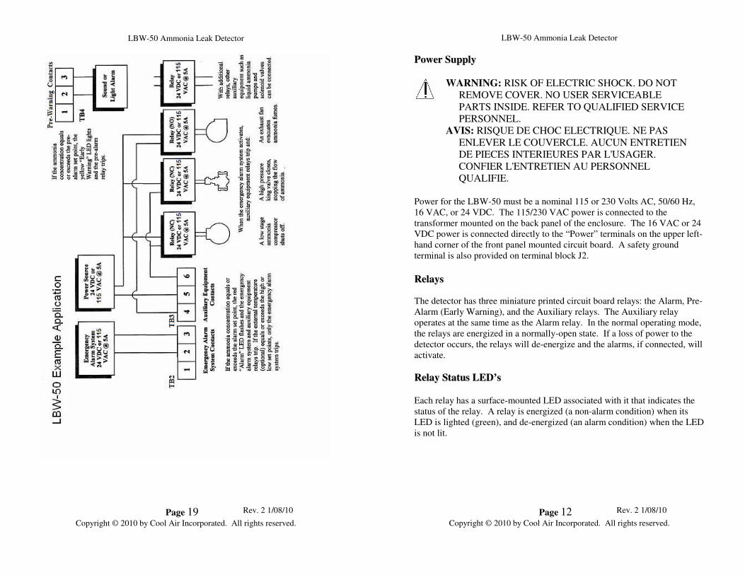
LBW-50 Example Application
This schematic on the next page illustrates an example application.

LBW-50 Ammonia Leak Detector
Page 14 Rev. 2 1/08/10
Copyright © 2010 by Cool Air Incorporated. All rights reserved.
LBW-50 Ammonia Leak Detector
Page 17 Rev. 2 1/08/10
Copyright © 2010 by Cool Air Incorporated. All rights reserved.
IINNSSTTAALLLLAATTIIOONN AANNDD SSEETTUUPP
Caution: Do not apply power to the detector until instructed to do so.
The detector comes with four mounting feet, packaged in the detector
enclosure for shipment. Use the directions that accompany the mounting
feet for mounting the detector enclosure.
The detector should be mounted in a location where ammonia leaks are most
likely to occur, such as near valve groups, compressors, and refrigeration
coils. Be sure the detector is visible and easily accessible. Avoid locating
the detector where it might be damaged by forklift traffic and/or any other
types of external activity. In washdown areas, please make sure the sensor is
protected from washdown by installing our optional stainless-steel
wahsdown tube. It is important not to install the detector (specifically the
sensor) in designated smoking areas, as even a minute concentration of
smoke will set off the alarm.
WARNING: RISK OF ELECTRIC SHOCK. DO NOT
REMOVE COVER. NO USER SERVICEABLE
PARTS INSIDE. REFER TO QUALIFIED SERVICE
PERSONNEL.
AVIS: RISQUE DE CHOC ELECTRIQUE. NE PAS
ENLEVER LE COUVERCLE. AUCUN ENTRETIEN
DE PIECES INTERIEURES PAR L'USAGER.
CONFIER L'ENTRETIEN AU PERSONNEL
QUALIFIE.
The detector is set at the factory to operate on 115 VAC. When power is
first applied to the detector in the field, it will immediately go into Alarm
status and the LED’s will indicate a large ammonia concentration. This is
normal. When the sensor warms to normal operating temperature (usually
about a minute) the detector will return to a non-alarm status. For this
reason, the detector must be placed in service mode before applying power to the detector to avoid nuisance alarms. Once the LED’s are no
longer lit up, set the service switch back into the normal mode.

LBW-50 Ammonia Leak Detector
Page 15 Rev. 2 1/08/10
Copyright © 2010 by Cool Air Incorporated. All rights reserved.
LBW-50 Ammonia Leak Detector
Page 16 Rev. 2 1/08/10
Copyright © 2010 by Cool Air Incorporated. All rights reserved.