lbi-39067b - site grounding and protection. objective the fundamental objective of this document is...
TRANSCRIPT

ericssonz
LBI-39067B
Standard for Site Grounding and Protection

This manual is published by Ericsson Inc., without any warranty. Improvements and changes to this manual necessitated by typographical errors, inaccuracies of current information, or improvements toprograms and/or equipment, may be made by Ericsson Inc., at any time and without notice. Such changes will be incorporated into new editions of this manual. No part of this manual may be reproduced ortransmitted in any form or by any means, electronic or mechanical, including photocopying and recording, for any purpose, without the express written permission of Ericsson Inc.
Copyright © June 1994, Ericsson, Inc.
NOTICE!The software contained in this device is copyrighted by Ericsson Inc. Unpublished rights are reserved under the copyrightlaws of the United States.
NOTERepairs to this equipment should be made only by an authorized service technician or facility designated by the supplier.Any repairs, alterations or substitution of recommended parts made by the user to this equipment not approved by themanufacturer could void the user’s authority to operate the equipment in addition to the manufacturer’s warranty.
NOTICE!
This manual covers Ericsson and General Electric products manufactured and sold by Ericsson Inc.
Table of ContentsPage
1. OBJECTIVE ...................................................................................................................................................... 31.1. GROUND THEORY........................................................................................................................... 31.2. SCOPE................................................................................................................................................. 31.3. GENERAL .......................................................................................................................................... 41.4. RESPONSIBILITY............................................................................................................................. 4
1.4.1. Minimum Requirements .......................................................................................................... 41.5. PROCESS & DEFINITION ............................................................................................................... 4
1.5.1. Coax and Transmission Line Grounding ................................................................................ 41.5.2. Equipment Grounding ............................................................................................................. 5
1.6. GROUND WIRE COMPOSITION ................................................................................................... 51.6.1. Ground Rods ............................................................................................................................ 5
1.7. CONDUCTORS.................................................................................................................................. 51.8. CONNECTIONS ................................................................................................................................ 5
1.8.1. Below Ground .......................................................................................................................... 61.8.2. Above Ground .......................................................................................................................... 6
1.9. SURGE SUPPRESSION DEVICES.................................................................................................. 71.9.1. The Following Practices Are to be Avoided!......................................................................... 7
2. EXTERNAL GROUNDING SYSTEM ........................................................................................................... 72.1. ANTENNA TOWER GROUNDS...................................................................................................... 7
2.1.1. Wooden Antenna Poles ............................................................................................................ 72.1.2. Self Supporting Lattice Towers ............................................................................................... 72.1.3. Guyed Lattice Towers .............................................................................................................. 72.1.4. Antenna Support Structures On Buildings ............................................................................. 8
2.2. EQUIPMENT BUILDINGS............................................................................................................... 82.3. BULKHEAD PANEL ......................................................................................................................... 82.4. FENCES .............................................................................................................................................. 8
2.4.1. Nearby Metal Objects;............................................................................................................. 92.5. TRANSMISSION LINES .................................................................................................................. 9
2.5.1. Shield Grounds......................................................................................................................... 92.6. COAXIAL SUPPRESSOR................................................................................................................. 92.7. TOWERTOP PREAMPLIFIERS ....................................................................................................... 92.8. TOWER-MOUNTED MICROWAVE AND REPEATER EQUIPMENT...................................... 102.9. COMMUNICATIONS EQUIPMENT ROOM INTERNAL GROUNDING ................................ 10
2.9.1. Grounding Of Equipment Cabinets, Racks, And Shelves ................................................... 102.9.2. CABLE TRAYS ..................................................................................................................... 10
3. PLANS AND DOCUMENTATION ............................................................................................................... 11
LBI-39067B
2

1. OBJECTIVE
The fundamental objective of this document is to providea standard for Ericsson site equipment grounding, with rec-ommended methods that are essential to protect personnel,minimize component failure, and optimize performance byreducing electrical noise. Transient voltage introduced intoa system often exceeds the operating parameters of electroniccomponents and has destructive results. The fragile natureof semiconductors makes them even more susceptible tothese externally induced transient voltages.
An effective ground system should include considera-tions that fulfill its purpose. These purposes are:
• Protect personnel by reducing the hazards of elec-trical shock.
• Provide a non-destructive low inductance path toground for lightning strikes and currents.
• Provide a low inductance path to ground from cableshields and other metal encased RF handling de-vices (antennae etc...).
• Protect wiring and other electrical componentsfrom damage.
• Reduce noise and suppress damaging power spikes.
1.1. GROUND THEORY
All communications facilities are related to ground orearth either by capacitive coupling, accidental contact ordesigned contact. If a conducting path for a lightning strokeis provided between the point of contact of a strike to anedifice and a suitable ground apparatus or electrode, damageand shock hazards can be diminished.
In theory, a ground rod 1 inch in diameter driven intohomogeneous 1000 ohm per meter (ohm/meter) soil for onemeter would present only 765 ohms. Driving it anothermeter into the soil (two meters) would yield 437 ohms.Extending the depth to three meters would yield about 309ohms.
By using three ground rods that are each one meter long,and driven into the same soil area one meter deep and onemeter apart we could achieve a ground resistance of 230ohms.
We quickly realize that we can get faster ohms reductionin ground resistance by installing multiple ground rods. Ifwe also bury the interconnecting wire below the soil surfacewe are able to lower the ground resistance below 200 ohms.
With these conditions as a point of reference, theERICSSON site installation should exhibit better than (be-low) five (5) ohms resistance between any connected pointon the ground bus and earth ground. The exception to this
requirement is noted at section 2.1.4, ANTENNA STRUC-TURES ON TALL BUILDINGS.
When making these measurements, an instrument similarto the AEMC Model 3700 HD will be used to make thesemeasurements. The measurements will be made using theinstructions provided with the AEMC model 3710HD(ERICSSON CAT # LYAEMC_3710) or AEMC 3730(ERICSSON CAT # LYAEMC_3730) Ground Test Instru-ment.
Where ground measurements are to be made prior to siteconstruction or where no present ground connections exist,it is recommended that a three or four point ground measure-ment be made and recorded. The use of an AEMC model4500 (ERICSSON CAT # LYAEMC_4500) (or equivalent)digital ground test meter may be employed. If the equipmentis not readily available, there are many electrical contractorsand some power utilities who provide this service for a fee.
1.2. SCOPE
This standard has been prepared for both safety anddamage prevention measures. The grounding, bonding, andshielding procedures are implemented to prevent damage toequipment, reduce Radio Frequency spectrum pollution andas a safety measure for maintenance and operating personnel.
The prime source of danger and damage is from lightningcurrents which are often conducted to the equipment by wayof the coax transmission lines.
This document is to be used as a guide for the design andinstallation for protective bonding and grounding of allEricsson radio and dispatch installations.
The isokeraunic (isobar levels) map shown in figure seven(7) attached to this document shows the mean annual numberof days with thunderstorms in the United States. NOTE: Theregion with the highest frequency is centered around southand central Florida.
One of the better means to reduce the chance of damagefrom this source is to provide a low impedance path to groundfor these currents without having the currents flow throughthe equipment.
Another means to control surge ingress via the electricalutility service is by installing a PolyPhaser Model PM240-BP(see figure 9), Joslyn Model 1265-85 or ERICSSONapproved equivalent AC MOV and avalanche surge arresteron the incoming power lines. Additional surge protection(PM240-BP/figure 9) downstream of the breaker panel maybe added for extra protection. Ericsson transmitting equip-ment is equipped with internal avalanche and MOV protec-tion.
LBI-39067B
3

1.3. GENERAL
The following needs constitute a justification for ground-ing:
1) The need to control fast-rising electrical surges, whichproduce high voltage differences between the ends ofsingle conductors such as heavy copper wires and bars.
2) The need to equalize surge potentials by controlled bond-ing of Ericsson Communications site ground elements.
These elements include the following:
a) Non Isolated Ground Zones (IGZ ) equipmentgrounds.
b) Surge Producers
c) Surge Absorbers (provides path to ground)
d) IGZ Grounds
3) The need to reduce voltage differences and control surgecurrents by using single-point grounding, which includesthe following elements:
a) A common or master ground bar configuration forestablishing a common voltage reference plane(with respect to earth "true" ground) for the entireEricsson communications site and for dispersinglightning and power surge activity rapidly to earthvia the halo and ring ground system.
b) A ground window bar (see appendix “A”, figureA3), or equivalent (Half-hard copper cable entrybulkhead by PolyPhaser®), to establish a localpoint of reference potential for grounding sensitiveelectronic equipment. This is terminated on themaster ground window as the single point groundand voltage reference for all equipment at theEricsson communications installation.
c) A single ground point in the Isolated Ground Zoneis at the master ground window. This again insuresthat potential equalization is true to any attachedground windows, and equipment.
d) The single point master ground bar will be cleanedto remove any oxidation to insure a low resistanceconnection. To establish sufficient metal to metalcontact, an anti corrosion or antioxidant material(paste) is added at connecting points where ground-ing conductors are terminated. A complete descrip-tion of the single point master ground is shown indetail in appendix A, figure A3 of this document.
1.4. RESPONSIBILITY
Throughout this document there will be references toground rods and ground connections. In all cases mentionedthere will be only one ground system at each site, building,room, or communications shelter. ALL GROUNDS ARETIED TOGETHER (see figure 1).
There should be no separately maintained ground rodsor ground systems that are associated with the communi-cations shelter, site, building, or equipment room. Adher-ence to these requirements becomes the performancestandard with respect to Ericsson Private Radio Systemscommunications facilities.
1.4.1. Minimum Requirements
The purpose of this specification is to establish minimumrequirements for a grounding system which will provide ameasure of personnel and equipment protection. In the eventthat any item specified within this document conflicts withthe National Electrical code or local buildinggrounding re-lated codes, those Codes may take precedence.
Protective measures to prevent equipment damage andpersonnel hazards against lightning will incorporate systemgrounding and bonding using good RF practices. While allconductors and connections have some associated resistance,the inductive reactance is normally much larger. All ground-ing and bonding conductors have low inductance intercon-nections to minimize the inductive voltage transients.
1.5. PROCESS & DEFINITION
As stated in the general overview of this document, allelements of the ground system, and conducting elements innear proximity to the system are connected and bondedtogether. This performs the function of maintaining any andall parts of the radio site at the same ground integrity, asrelated to true earth ground (see figure 1).
1.5.1. Coax and Transmission Line Grounding
At Ericsson repeater sites and antenna tower locations,our installers must attach a minimum of three lightningprotection grounding kits to each coaxial line used at the site.Where vertical cable runs on towers exceed 200 feet, agrounding kit should be installed at 100 foot intervals. Thisprocess is illustrated in more detail in figure one, specificallypoints 1, 2, & 3. Grounding kits are shown in figure 13 andphotos B11 & B12 of this document.
Each coax run will have an ANDREW ARRESTOR Pluslightning surge protector (see appendix “B” figure B6) orPolyPhaser® gas tube type (or equivalent), lightning arrestorinstalled onto the coax near the cable entrance to the com-munications shelter or room. The Andrew ARRESTOR Plusare the preferred types and are believed to be the best light-
LBI-39067B
4
ning arrestors presently available. The ARRESTOR Plus isa multi-stike protection device that also optimizes IM per-formance.
These grounding kits will be terminated onto the masterground bar. All connections to the master ground bar win-dow will be clean and free of any oxidation to insure a lowresistance connection. Each of these arrestors are effectivein limiting the amount of lightning energy that can be trans-ferred to the equipment via the inner conductor of the coaxor transmission line.
1.5.2. Equipment Grounding
Each equipment rack, equipment cabinet, or equipmentshelf will be grounded to a site ground via the inner buildingground window. In the case of communications shelters, theequipment enclosures will be attached to the main groundwindow in the same manner to this system "halo" ground.
1.6. GROUND WIRE COMPOSITION
No grounds will be run inside metal conduits becausemetal conduits increase the surge impedance and inductanceof the grounding cables. The grounds which make up theinterior "halo" ground will be of number 2 AWG or largercopper wire covered with a nonconductive approved plasticcovering. This covering is light green. Where the haloground is attached to exit ground wires, these wire(s) will besolid, tinned, bare copper, number 2 AWG or larger.
A complete grounding system for the antenna, towers,and buildings are provided. These include internal and ex-ternal grounding systems for equipment in the communica-tions buildings, grounding of the antenna towers and guys,transmission line, telephone line and AC power line ground-ing, and grounding of the Communications facility.
1.6.1. Ground Rods
Where an Ericsson ground system is installed, groundrods will be bare copper or copperclad steel, 5/8 inch indiameter, and a minimum of 8 feet in length. As discussedin "General" (1.3) at the beginning of this document, mul-tiple interconnected ground rods are normally provided (seefigure 1).
To maintain the integrity of the ground system, wherespace permits, a minimum distance between ground rods willbe 10 feet. Exothermic bond/weld connections will be madeat all ground rod connections.
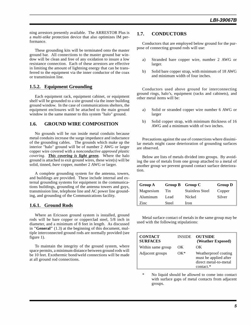
1.7. CONDUCTORS
Conductors that are employed below ground for the pur-pose of connecting ground rods will use:
a) Stranded bare copper wire, number 2 AWG orlarger.
b) Solid bare copper strap, with minimum of 18 AWGand minimum width of four inches.
Conductors used above ground for interconnectingground rings, halo’s, equipment (racks and cabinets), andother metal items will be:
a) Solid or stranded copper wire number 6 AWG orlarger
b) Solid copper strap, with minimum thickness of 16AWG and a minimum width of two inches.
Precautions against the use of connections where dissimi-lar metals might cause deterioration of grounding surfacesare observed.
Below are lists of metals divided into groups. By avoid-ing the use of metals from one group attached to a metal ofanother group we prevent ground contact surface deteriora-tion.
Group A Group B Group C Group D
Magnesium Tin Stainless Steel Copper
Aluminum Lead Nickel Silver
Zinc Steel Iron
Metal surface contact of metals in the same group may beused with the following stipulations:
CONTACTSURFACES
INSIDE OUTSIDE (Weather Exposed)
Within same group OK OK
Adjacent groups OK* Weatherproof coatingmust be applied afterdirect metal-to-metalcontact.*
* No liquid should be allowed to come into contactwith surface gaps of metal contacts from adjacentgroups.
LBI-39067B
5

1.8. CONNECTIONS
All ground connections shall be made with minimumlength conductors, with straight vertical (or horizontal) runs,if possible. Conductor bends, when required, will be greaterthan 12inch radius. Connecting conductors will always tran-sition in the direction of current flow or toward earth ground,and approach the main ground at an angle of roughly 45degrees.
All exothermic protection connections made to theground system, including test leads shall be made with anexothermic protection exothermic welding process specifi-cally designed to restrict heat energy transfer to surroundingobjects.
EXOTHERMIC OR PERMANENT GROUNDINGCONNECTIONS
Exothermic power & grounding connections are madewith a pre-engineered system using a controlled exothermicchemical reaction. exothermic connections offer the follow-ing advantages over other types of connections:
• The connection permanently welds every strand ofthe conductor.
• The connection is made with portable equipmentwhich requires no outside source of heat or power.
• Loosening or corrosion of the current path cannotoccur.
• The connection is able to withstand repeated highcurrent surges [faults] without damage to the con-nection or the conductor
• No special skills and minimum training is required.
• Installation time is the same as other kinds of con-nector.
PERMANENT GROUNDING CONNECTIONSPECIFICATIONS
All grounding conductor to conductor, conductor toground rod and conductor to structure and fence post con-nections of #6 AWG and larger copper conductors shall bepermanent exothermically welded connections. Coppergrounding conductors spliced with exothermic connectionsshall be considered as a continuous conductor, as stated inNEC 250-81 Exception No. 1 and 250-91 Exception No. 3.
All connections shall meet the applicable requirements ofIEEE Std 80-1986. For this reason, the CADWELD® exo-thermic connections are suggested as they are approved inNEC 250-81, -91, -113, and -115.
Welding material for copper-to-copper and copper-to-steel connections shall contain copper oxide, aluminum and
not less than 3 percent tin as a wetting agent. Startingmaterial [if used] shall consist of aluminum and copperoxides. It shall not contain phosphorous or any caustic, toxicor explosive substance.
Weld metal shall be controlled at the point of manufactureand subjected to rigid quality control inspection procedures.
1.8.1. Below Ground
(CADWELD® is a bonding process that provides a me-tallic bridge connection that exhibits virtually no resistanceand its conductivity approximates that of the associatedconductors). Connections made to ground rods, or to con-ductors below ground must be made using an exothermicprocess such as Cadweld® or equivalent. This attachmentprocedure ensures firm, mechanically rigid, and mainte-nance free connections. Connecting and interconnectingconductors are placed at the same depth as the top of theground rods.
DOPING OF GROUND SYSTEMS
When unable to achieve grounds below 10 ohms, somedoping of the earth may be necessary. One of the bestmethods used today to increase the conductivity (reduceresistance) of the ground is another CADWELD productcalled “GEM®.” (ERICO® GROUND ENHANCE-MENT MATERIAL) If GEM® is unavailable, a clay-saltscompound called “BENTONITE” or “LYNCONITE” maybe used. ERICO ® Catalog A7J provides more detailedinformation. LYNCONITE is available from LynCole, themakers of the “XIT” ground systems. If a more effectiveground is needed, the “XIT” ground devices may fulfill thisrequirement (see Figure 11).
APPLICATION
ERICO Ground Enhancement Material, GEM, is a supe-rior, conductive material that improves grounding effective-ness regardless of soil conditions. It is an ideal material touse in areas of poor conductivity soil, such as rocky ground,mountain tops and sandy soil. GEM is added around aground rod in an augured hole or around a conductor in atrench. The GEM material effectively increases the effectivediameter of the rod or conductor.
GEM SPECIFICATIONS
Ground enhancement material shall be ERICO GEMhaving a constant cured resistivity of 12 ohm/cm or less. Itshall set up to a hard, permanent material and shall notdecompose or dissolve over time. It shall not require anymaintenance after installation. It shall not rely on the con-tinuous presence of water nor shall it add salts to the earthwhich may contaminate the ground water. The material shallbe packaged in 25 pound bags and may be added dry orpre-mixed in a slurry like cement.
LBI-39067B
6
1.8.2. Above Ground
Where possible, connections made above ground, in areasexposed to weather, the Cadweld® or similar process will beemployed. If environmental conditions prevent the use ofthe Cadweld® process, the use of an appropriate pressure-type connection will be used.
Where above ground pressure type connections are em-ployed, stranded wire will be used. Connections made aboveground will be made with appropriate passivation of themating surfaces, or use special transition clamps such asPolyPhaser Model J1, J2, or equivalent.
Connections of stranded conductors to equipment racksis made using lugs or pressure clamps consistent with thewire size, and grounding surface of the equipment beinggrounded. Connections to tower guy wires will use pressureconnections.
1.9. SURGE SUPPRESSION DEVICES
Manufacturer Surge suppression device types referred toin this document are recommended and may be substitutedas long at the substitution is of the same quality and performsthe same function. Consideration must be given to voltageclamping level, response time, and energy rating for theintended application. Power line surge suppressors similarto the PolyPhaser PM240-BP (see figure 9) should be in-cluded at the service entrance breaker panel. Other types thatserve that provide similar service is the “E-CLIPS” andJoslyn.
1.9.1. The Following Practices Are to beAvoided!
a) Ground wire runs through metal conduit. If anoccasion presents itself where the ground must becarried through a metal conduit, the ground wiremust be bonded at each end of the conduit. Theuse of PVC conduit is preferred. (Where the wireground exits the communications room or shelter;see appendix “A”, figure A1).
b) Reliance on the third wire (green wire) on ac powerlines for lightning ground.
2. EXTERNAL GROUNDINGSYSTEM
External grounding rings installed by Ericsson or ap-proved contractors will individually encircle the antennatower, the building, or equipment shelter.
Ground rods for the tower and building are installed sothat the top of the rod(s) is minimum of 12 inches below soilsurface. The ground rods for tower ground will be installedso that the bottom end of the rod is deeper than the lowestpart of the tower footing.
Each ground ring listed above, such as the tower, build-ing, fence, or other object will be interconnected with aminimum of two stranded copper wires number 2 AWG orlarger. Where the “PolyPhaser Earthed Etrance Panels”(PEEP) is employed (figure 8) or the Andrew ARRESTOR-Port Plus (figure 12), copper straps will be prepared andconnected as shown in figure 10 and appendix “B” figuresB9 and B10. Where possible, connections to the groundrings will be made using an exothermic (Cadweld process orequivalent; see appendix “B” attached) weld.
2.1. ANTENNA TOWER GROUNDS
Where monopole masts are employed, the ground systemwill consist of a minimum of three ground rods, connectedtogether per the section on "Conductors: Below ground."
The mast connection to the ground system will be madewith stranded wire number 2 AWG or larger. Connections tothe mast will be in accordance with the manufacturer’sinstructions or use the exothermic “CADWELD®” method.The connections will be short and direct with no sharp bends.Typical interconnections are shown in figure 5 attached tothis document.
2.1.1. Wooden Antenna Poles
At installations where wooden antenna poles might beemployed, the grounding system will consist of a minimumof two ground rods connected together and installed as perthe paragraph "Conductors: Below ground."
Atop the pole, ground connections to the antenna orantenna mast are made per manufacturer recommendations.A number 2 AWG or larger stranded copper ground wire willbe run down the pole, and away from all other conductors toavoid possible flashover.
2.1.2. Self Supporting Lattice Towers
The self supporting lattice tower grounding system con-sists of a ground rod at each tower leg. If necessary, addi-tional ground rods may be used to decrease ground resistancewhere needed, or be used to reduce the distance betweenrods. Ground rods must be connected together per paragraph"Conductors: Below ground." Each tower leg is connectedto the grounding system with number 2 AWG stranded wireor larger. Connections to the tower leg will be short and directwith no sharp bends.
LBI-39067B
7

2.1.3. Guyed Lattice Towers
The guyed lattice tower grounding system consists ofthree ground rods at the tower base. These ground rods mustbe connected together per paragraph " Conductors: Belowground." The ground conductors used connect the groundingsystem will be number 2 stranded wire or larger. Connec-tions to the tower will be short and direct with no sharpbends.
In addition to the tower leg grounding, a ground rod mustbe installed at each guy anchor point approximately one footfrom the anchor footing. The top of the ground rod will bea minimum of 12 inches below soil surface. The bottom ofthe ground rod will extend below the lowest point of theanchor footing.
Number 2 AWG stranded copper wire is used to connecteach of the guy wires to the ground rod at the guy anchor.Each ground rod is to be tied back to the tower "ground ring"below ground, using number 2 stranded copper wire.
2.1.4. Antenna Support Structures On Buildings
Radio antenna installations atop buildings will have thetower, down conductors, transmission line shields, and otherconducting objects within 6 feet of the tower or antenna basesecurely bonded together per paragraph "Conductors:Above ground" (1.7) and "Connections: Above ground(1.8-1.82)."
Atop steelframe structures, where possible, the commonbond point may be bonded to building steel with number 2AWG or larger, copper wire. If available, the tower may alsobe bonded at roof level to a large metal, earth grounded, coldwater pipe.
Atop reinforced concrete buildings, the common bondpoint should be connected via number 2 AWG or larger,stranded copper down conductors. These may be bonded tothe earth grounded cold water main in the basement of thebuilding or bonded to the building ground system. If avail-able, the tower should also be bonded at roof level to a largemetal, earth grounded, cold water pipe.
2.2. EQUIPMENT BUILDINGS
External "halo" ground is the grounding system aroundthe exterior of the communications shelter or building. Thisground system consists of a ground rod at each corner of thebuilding. As necessary, additional ground rods will be addedsuch that the distance between rods is less than 10 feet.
A ground rod is installed directly below the coax trans-mission line entrance to the building. Ground rods arespaced approximately 2 feet out from the perimeter of thebuilding.
2.3. BULKHEAD PANEL
A weatherproof metal bulkhead panel should be installedon the building equipment wall (see figure 10). The panelwill be comparable to the Andrew ARRESTORPORT Plus orthe “PolyPhaser Earthed Entrance Panels” or “PEEP” (seeappendix “B” figures B6 and B7 and/or figure 8) models(photos and drawings are a part of this document). The sizeshould be determined by the number and size of transmissionlines interconnecting through it (figure 8 shows demen-sions). Insure that appropriate cable boots are used to weath-erproof the connections.
The external panel must include a ground bar for trans-mission line shield ground connections and connections tothe external ground system (see figure 10 and appendix “B”figure B9). The ground bar should be fabricated to avoiddissimilar metal connections as stated in this document (seeappendix “A” figure A3 attached; see also paragraph "Con-ductors: Above ground."). The ground bar (appendix A,figure A3) must be connected to the building external ground
Guy wires associated with towers atop buildings shouldbe grounded at their anchor points to a common bondpoint in the same manner as for grounding terrestrialtowers. A dissimilar metal interconnect device will beused between the guy wire and the ground wire. Wherethe ground wire from multiple guys are daisy-chained,there will be at least a three inch "play" loop betweenguy-to-guy ground connections. In the above case wheretall building grounds are in use, the ground resistanceshould be maintained below(better than) ten (10) ohmsbetween any equipment connected ground buss and earthground. When making these measurements, an instru-ment similar to the AEMC Model 3700 HD will be usedto make these measurements. The measurements will bemade using the instructions provided with the AEMC3710 (ERICSSON cat # LYAEMC_3710) Ground TestInstrument.
IMPORTANTNOTE
LBI-39067B
8

system by number 2 AWG (2 conductors or copper strapsmay be employed to form a low inductance path to the systemground).
An internal sub panel is not necessary when using theAndrew ARRESTORPORT Plus. Several features are builtinto the Andrew ARRESTORPORT Plus that eliminate addi-tional connectors and options that are associated with thePolyPhaser Earthed Etrance Panels. The Andrew AR-RESTORPORT Plus & the PolyPhaser Earthed EtrancePanels.(see appendix “B” figure B7 & figure 10), bolteddirectly to the bulkhead panel with multiple bolts may beused to mount the transmission line surge suppressor speci-fied in paragraph "Quarterwave stub & Coaxial Suppressor."The subpanel must be securely fastened with a low resis-tance, low inductance path to the bulkhead panel (strandedNo. 2/0 AWG or larger).
2.4. FENCES
Where possible to do so, metal fences within 6 feet of anyground ring or any grounded object will be grounded attwenty foot intervals along its length or at a minimum of eachcorner post and at each gate metal support post. This is toprovide additional shock hazard protection from lightning.Fences which are around the site, yet outside 8 feet of theperimeter grounds should be grounded at fifty (50) feetintervals along its length.
A minimum 8foot 5/8 inch copper or copperclad groundrod shall be installed into the ground within one foot of thefence, near a fixed gate hinge post where appropriate. Thetop of the ground rod will be a minimum of 12 inches belowthe ground surface (see figure 3 & 4 for similar connections)or at the same level as the external ground ring to which itwill be connected. Additional ground rods may be installedfor each 50 feet of fence, at equal spacing outside 6 feet ofthe ground system but surrounding the facility.
Each ground rod will be connected underground by themost direct path to the nearest tower or building ground ringusing a stranded copper wire, number 2 AWG or larger(seefigure 3).
Above ground connection will be made by use of exother-mic weld or a pressure clamp near the bottom of the metalpost. If below ground connections are used, it will be madeby exothermic weld (Cadweld®). Tinned copper groundstrap (braid) is used to connect metal fence gate(s) to themain post. Pressure clamps are employed with these connec-tions.
2.4.1. Nearby Metal Objects;
The following components are connected to the externalgrounding system using a number 2 AWG (or larger)stranded copper wire.
a) The transmission line entry window into the build-ing, as this is the entry point into the equipmentarea. All transmission lines are grounded to thiswindow, and extra care is employed to ensure a verylow inductance path to ground.
b) Ice shield and exterior cable tray between tower andbuilding.
c) Emergency generator and any generator supportingplatform or base.
d) Fuel tank(s), above or below ground.
e) Other large metal or conductive objects within 6feet of the communications shelter, tower, or thesystem ground.
f) To other ground systems provided by telephonecompany, or the electric utility provider(s). Localelectric codes should be observed when making thisattachment.
2.5. TRANSMISSION LINES
The following applies to the antenna and transmissionlines outside the communications shelter or building whereentry is made into the equipment shelter (see appendix “B”figure B6). These requirements do not apply to antenna andtransmission lines that are contained entirely within theequipment room or communications shelter.
2.5.1. Shield Grounds
The outer conductors of coaxial transmission cables mustbe grounded with an appropriate coaxial cable grounding kit(see figure 13 and appendix “B” figure B12 ). These ground-ing kits are installed at three points on the cable. Thegrounding locations are as follows:
1) Immediately outside the cable entrance to the equipmentroom, shelter, or building. This ground is attached priorto the phaser type lightning suppressor.
2) At the bottom of the vertical run of cable, at a point nearand above the bend onto the icebridge or support tressel.This grounding point should be as near the ground aspossible.
3) The top end of the vertical cable run near the terminationor antenna. This point is grounded or bonded to the towerby means of the clamp supplied as part of the groundingkit.
All three points should be grounded in accordance withthe recommendations provided in the grounding kit instruc-tions. These instructions are included in kits similar to theAndrew cable grounding kit described in figure 13. ThePolyPhaser UNI-Kit is shown in Appendix B, figure B11 andB12.
LBI-39067B
9
Additional information is shown at points labeled 1, 2, &3 in figure 1 of this document.
2.6. COAXIAL SUPPRESSOR
Quarterwave shorted stub or Coaxial Suppressors shouldbe installed at cable entrance of the building or communica-tions shelter. This suppressor should be bonded to the nearbyground bus plate to remove surge currents from the centerinductor of the cable(s).
2.7. TOWERTOP PREAMPLIFIERS
In cases where towertop amplifiers are employed that useDC supplied via the coaxial transmission line, Ericsson willinsure that an impulse suppressor similar to the PolyPhaserISDC50LN DC “ injection” type is used. Certain tower topamplifiers are already equipped with this type protection (seefigure 2).
PolyPhaser type ISGC50LN “pick-off” surge suppressorshould be installed according the manufacturers instructionsas an additional protective measure at the input ports of thetowertop amplifiers or preamplifiers. This protection is inaddition to the Ericsson internal amplifier protective devices.All towertop preamplifier chassis must be grounded to thetower.
Where penetration of cable entry bulkheads are a part ofthe coaxial cables between the tower top amplifier and theEricsson communications equipment, an added protectiondevice may be required. The PolyPhaser IS-DC50LNZ pick-off and re-injector (PICKOR) may be employed. Figure 2provides illustrated details for the installation of thesePolyPhaser DC insertion and DC pick-off devices.
Where possible, DC ground, shuntfed antennas should beused as additional protection for the towertop preamplifiers.Antenna cable attachments to the antennas are kept as shortas possible.
2.8. TOWER-MOUNTED MICROWAVEAND REPEATER EQUIPMENT
For tower top repeaters, the input and output points arethe most important to protect. Tower, telephone or controllines are often overlooked. Coax line protectors are em-ployed in the Ericsson repeater inputs and outputs, and thepreamp front end. Power line protectors must be local andsingle point grounded at the top with the equipment. Theneed for power protection is doubled for tower top repeaterand preamp installations where 120 or 240 VAC is being fedup the tower.
Above 18 GHZ, microwave equipment usually has aGunn (microwave diode) down converter located on the backof the dish, being powered through one or two coaxial lines.These lines also handle the uplink and down link frequenciesas well as AFC (Automatic Frequency Control) error infor-mation.
Protectors similar to the Poly-Phaser IS-MD50LNZshould be employed at the top and bottom to properly protectthe equipment. A device similar to the PolyPhaser IS-DC50LNZ is another type of protection used in these appli-cations and is fully transparent to all existing voltages andsignals from microwave equipment.
2.9. COMMUNICATIONS EQUIPMENTROOM INTERNAL GROUNDING
A Halo ground should be employed inside the communi-cations shelter. This Halo ground must be installed in theform of a "ring" in such a manner as to enable the use of shortlength conductor to be attached at the same ground windowas the equipment racks, cabinets, cable trays, and equipmentshelves.
This Halo is made of number 2 AWG stranded copperwire attached to standoffs (see appendix A, figure A2) atapproximately eight (8) feet above the equipment room floor.
Where the room or communications shelter has less than100 feet of perimeter, a minimum of four (4) ground risersare used. In any case, where possible, a ground riser is usedat each corner of the perimeter (see appendix A, figures A1& A2 ) . In installations where the perimeter of the equip-ment room exceeds 100 feet, a ground riser will be attachedat every twenty (20) feet of perimeter (see appendix A, figureA2). These ground risers are made of number 2 AWG SOLIDcopper which exit the room, or building via polyvinyl con-duits (see PVC exit method in appendix A, figure A1).
Where the ANDREW ARRESTORPORT Plus is installed,no quarterwave shorted stub can be used in the coax wherepower is being fed to a tower-top amplifier. Provisionsare made in the ANDREW ARRESTORPORT Plus toaccomodate feeding tower-top amplifiers using themethod shown in figure 2.
IMPORTANTNOTE
LBI-39067B
10

2.9.1. Grounding Of Equipment Cabinets,Racks, And Shelves
Each equipment cabinet or rack shall be equipped with aground bus that is attached to the main ground window andthe external system ground. Each equipment chassis securedin a cabinet or rack is connected to the cabinet or rack, groundbus. Equipment mounting rails are the preferred groundconnection points within the cabinets or racks. Attachmentsfrom the equipment cabinets and enclosures to the internalground window are made using number 6 (or larger) strandedcopper wire (see figure 10). Connections from these enclo-sures to the main ground window will be made using theshortest path length to diminish inductance.
2.9.2. CABLE TRAYS
Cable trays will be attached to the internal ground win-dow via number 2 AWG or larger stranded copper wire.Where mechanical connections (lugs, bolts) are made tointerconnect cable tray sections, an additional connectionwill be employed between cable tray sections (see insert textat figure 1) to ensure a good electrical ground connection(see appendix A, figure A4). Number 6 or larger, strandedcopper wire will be used.
Grounds between cable trays, equipment cabinets, equip-ment racks, and AC utility power enclosures will be vianumber 2 AWG or larger stranded copper wire.
When compression type connectors are employed at anEricsson installed site or system, the Burndy compression
system (or similar) may be used. This system consists ofconnectors for indoor taps, splices, and structural steel ter-mination’s. These connectors may be used in some Ericssonsites ground applications. The Burndy system connectorsare listed with Underwriters Laboratories under StandardUL467.
3. PLANS ANDDOCUMENTATION
Drawings and Ground reference documentation will re-flect the following items:
a) Grounding and bonding plan
b) Ground rods
c) Surge suppression devices
d) Bulkhead panel types
e) Coaxial cable grounding kit(s)
A prepared plan for lightning and surge protection meas-ures implemented into an Ericsson communications systemis submitted as a part of the overall system specifications.This plan takes into account such items as the radio installa-tion and equipment to be protected and local conditions.This plan must meet all requirements covered in this speci-fication, unless a specific written waiver is provided by thecustomer and agreed by Ericsson.
LBI-39067B
11

FIGURE 1
This drawing illustrates some of the grounding tech-niques described in this document. In addition it depicts howthe inside and outside “HALO” grounds are interconnected.Note that all wire bends and turns in the “HALO” groundring are smooth with no sharp points or bends. This samerule applies to the wires (shown in corners of the communi-
cations room) that interconnect the internal “HALO” to theoutside ground ring.
Note also that a copper cable entry bulkhead (PolyPhaser“PEEP”) and copper strap (2, 4, or 6 inch widths), may besubstituted for the inside copper ground bar and the # 2 or2/0 copper exit wire.
Andrew "ARRESTORPORT Plus"or the PolyPhaser "PEEP coax ca-ble entry
LBI-39067B
12

FIGURE 2
This figure depicts the method employed when supplying DC voltage to tower-top amplifier(s) using the PolyPhaser injectionand pick-off devices.
LBI-39067B
13

FIGURE 3
This drawing illustrates a typical transmit/receive site. Note areas of fence which come in close proximity to the towerand building grounds. All grounds are connected together. There are no separate ground systems at the same location.
FIGURE 4
“UFER” ground refers to steel and metal bars imbedded into concrete floors or tower foundations. The “UFER” ground shouldnever be relied as the exclusive or stand-alone site ground system.
LBI-39067B
14

FIGURE 5Typical “exothermic” welds made using the CADWELD method.
FIGURE 6Examples of the tools used to make exothermic welds
LBI-39067B
15
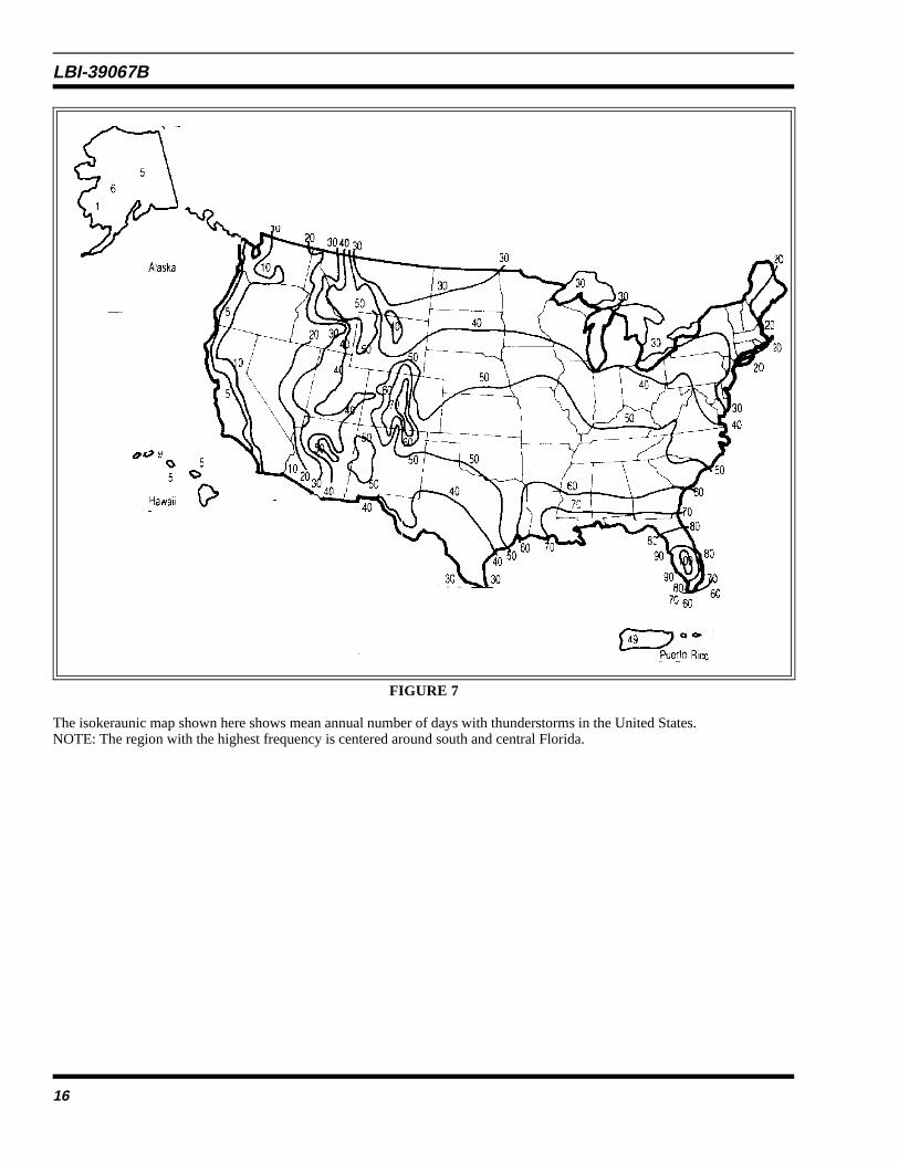
FIGURE 7
The isokeraunic map shown here shows mean annual number of days with thunderstorms in the United States.NOTE: The region with the highest frequency is centered around south and central Florida.
LBI-39067B
16

FIGURE 8
Typical installation of the PolyPhaser “PEEP.” Where walls exceed a usable depth, an inside and outside panel may be installed.Use number 2 or 2/0 stranded wire as a bond between the inside and outside panels.
LBI-39067B
17

FIGURE 9
The device shown here is an example of the MOV type used to clip or suppress power surges that could otherwise damageequipment. Other types similar to the above are manufacturered by “E-CLIPS” and Joslyn. (see sections 1.2 & 1.9 of thisdocument).
LBI-39067B
18

Figure 10
This drawing illustrates methods employed when attaching grounds and cable protective devices in an Ericsson installation. Notethat some installations will have copper strap between the bulkhead entry panel and the “HALO” ground ring. By using multipleconductors of # 2 AWG copper wire or 4 to 6” wide copper strap, inductance in the ground conductor is greatly reduced. In someinstallation the Andrew Arrestor-Port-Plus may be installed to enable easier access to the entry port coaxial connectors or wherethe desire to use “DIN” type connections (800 MHz). Use of the Arrestor-Port-Plus reduces the number of connectors requiredfor entry and grounding.
LBI-39067B
19

XITFIGURE 11
LBI-39067B
20

FIGURE 12
Andrew ARRESTOR-PORT Plus configuration and dimensions
ARRESTOR-PORT Plus CONFIGURATIONS:
LBI-39067B
21

FIGURE 13
Andrew cable “ground kits” for use when making 3 point ground connections at cable entry, tower base and tower top. Forcables that exceed 200 feet vertical run, include additional ground attachments at 100 foot intervals. For three point tower groundillustration see figure 1.
LBI-39067B
22
Appendix “A”
LBI-39067B
23

THE DRAWING SHOWN HERE DESCRIBE METHODS USED TO ATTACH INSIDE “HALO” GROUND RING TOTHE EXTERNAL GROUND RING (HALO).
FIGURE A1-”HALO” Attachments
NOTE: The PVC nipple is filled with silicone rubber or a sealant as a moisture barrier and pest deterrent.
LBI-39067B
24
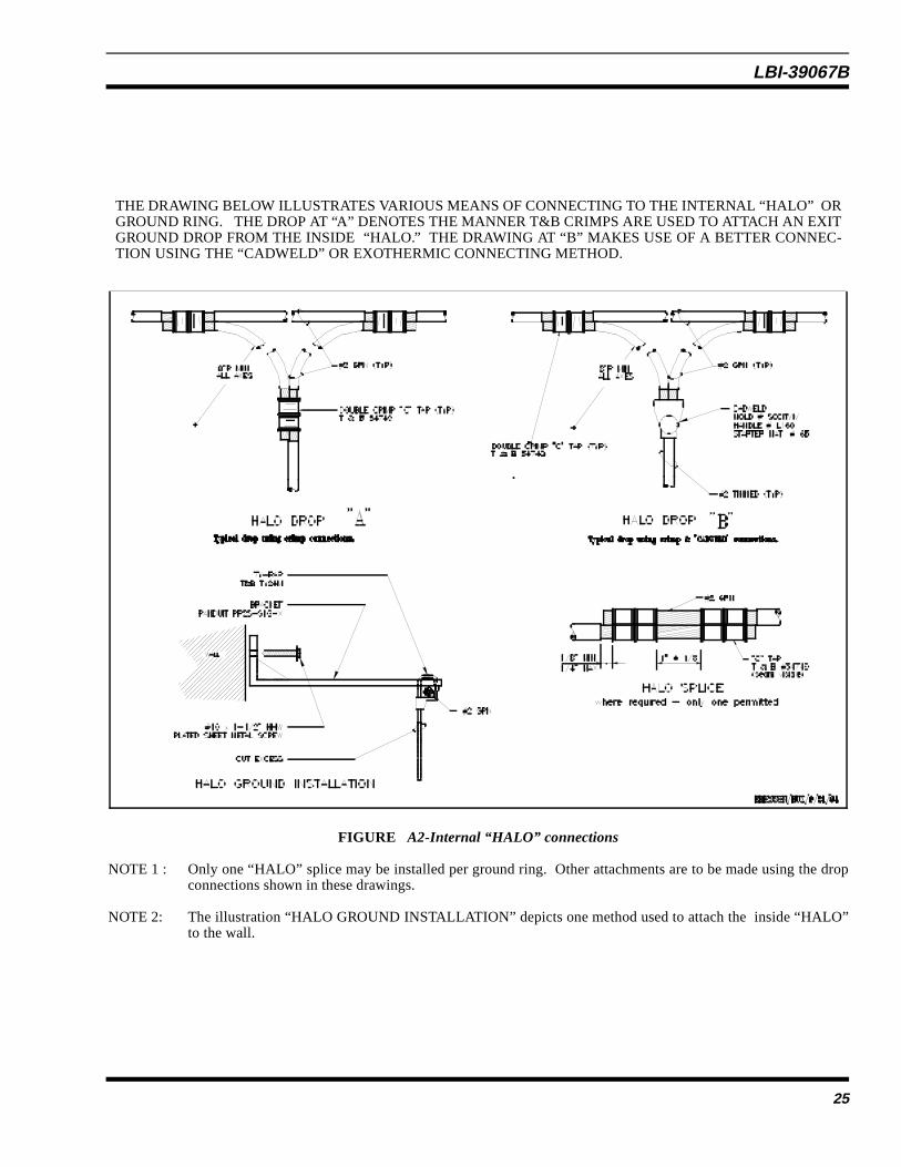
THE DRAWING BELOW ILLUSTRATES VARIOUS MEANS OF CONNECTING TO THE INTERNAL “HALO” ORGROUND RING. THE DROP AT “A” DENOTES THE MANNER T&B CRIMPS ARE USED TO ATTACH AN EXITGROUND DROP FROM THE INSIDE “HALO.” THE DRAWING AT “B” MAKES USE OF A BETTER CONNEC-TION USING THE “CADWELD” OR EXOTHERMIC CONNECTING METHOD.
FIGURE A2-Internal “HALO” connections
NOTE 1 : Only one “HALO” splice may be installed per ground ring. Other attachments are to be made using the dropconnections shown in these drawings.
NOTE 2: The illustration “HALO GROUND INSTALLATION” depicts one method used to attach the inside “HALO”to the wall.
LBI-39067B
25

When using a copper ground bar as a common point for internal shelter grounding, use one of the two methodsshown below to attach the ground bar to communications shelter wall.
FIGURE A3-Two Examples Of Ground-Bar Installations
Note: At “A” insulators are used to support ground bar, while insulated “shoulder washers” are use at “B” to support theground bar. In either case, the ground bar should be isolated from the shelter walls, support members, and studs.
LBI-39067B
26

THIS DRAWING ILLUSTRATES VARIOUS TECHNIQUES USED WHEN BONDING CABLE TRAYS AND METALDOORS. THESE CONNECTIONS ARE NECESSARY TO PRESERVE GROUND INTEGRITY TO ALL METALOBJECTS WITHIN THE COMMUNICATIONS SHELTER
FIGURE A4-Cable Ladder and Door Grounding
LBI-39067B
27
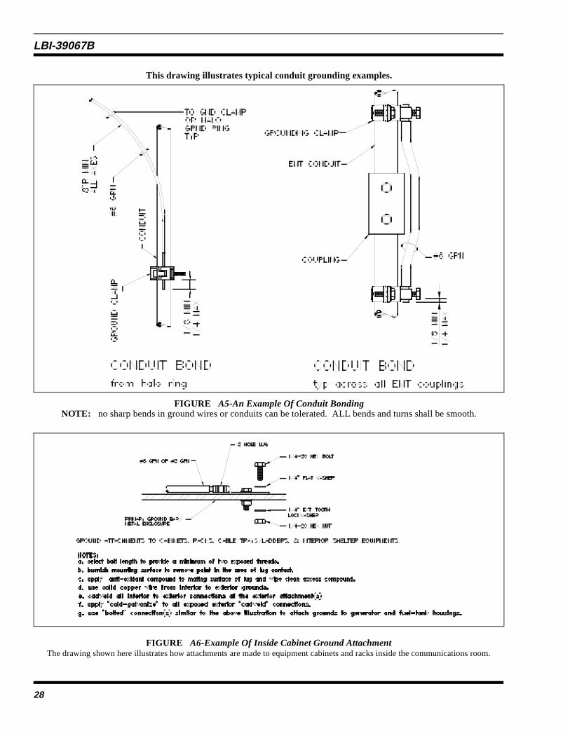
This drawing illustrates typical conduit grounding examples.
FIGURE A5-An Example Of Conduit BondingNOTE: no sharp bends in ground wires or conduits can be tolerated. ALL bends and turns shall be smooth.
FIGURE A6-Example Of Inside Cabinet Ground AttachmentThe drawing shown here illustrates how attachments are made to equipment cabinets and racks inside the communications room.
LBI-39067B
28

Appendix “B”
LBI-39067B
29

Photo courtesy CADWELD®
Figure B1 - Illustration of the exother-mic welding weld process.
STEP 1
Setting the mold and preparing the connection for exothermic welding.
STEP 2
Ignition of the exothermic weld compound (processing) which fusesthe connection.
STEP 3
Remove the mold and inspect the new connection.
Figure B3Procedures for Making Exothermic Welds
Figure B2 - Cut-A-Way Description of an Exothermic Weld.
LBI-39067B
30

Figure B4 - ACCEPT
A clean and smooth flow of the molten (fused) metals indicates a good weld.
Figure B5 - REJECT
Metals not fused and with intermixed slag coating indicate a poor connection and should be rejected.
LBI-39067B
31

No special orextra groundclamps areneeded becausethe ARRESTORPlus is attachedto the copperground bus by asingle copperbolt (provided).
Figure B6 - Arrestor-Port-Plus Coax Bulkhead Entry
Exterior view of ARRESTORPORT Plus coax cable multiport entry bulkhead. Note the ground bolt that allows easygrounding of coax shield using only an attached threaded copper bolt.
LBI-39067B
32
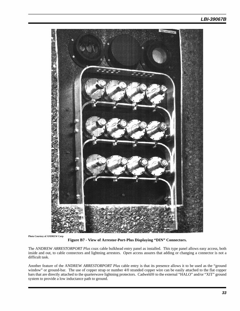
Photo Courtesy of ANDREW Corp
Figure B7 - View of Arrestor-Port-Plus Displaying “DIN” Connectors.
The ANDREW ARRESTORPORT Plus coax cable bulkhead entry panel as installed. This type panel allows easy access, bothinside and out, to cable connectors and lightning arrestors. Open access assures that adding or changing a connector is not adifficult task.
Another feature of the ANDREW ARRESTORPORT Plus cable entry is that its presence allows it to be used as the “groundwindow” or ground-bar. The use of copper strap or number 4/0 stranded copper wire can be easily attached to the flat copperbars that are directly attached to the quarterwave lightning protectors. Cadweld® to the external “HALO” and/or “XIT” groundsystem to provide a low inductance path to ground.
LBI-39067B
33

Figure B8 - Low Inductance Ground Strap Installation
Installation of “low inductance” ground straps are encouraged when and wherever possible. Note also the coax cable, multi-portbulkhead entry. Where contact is made between the copper ground straps and the bulkhead panel, no-oxy or copper based pasteis used to prevent oxidation and to provide added conductivity (see next photo).
NOTE: Copper straps are attached to a copper bar below surface and exothermic welded to the “HALO” ground.
LBI-39067B
34

Figure B9 - Doping Ground Connections
Doping connections between low inductance copper strap and below soil copper bar. Copper bar is then exothermic welded(Cadweld ®) to the ground ring (HALO). The use of no-oxy joint paste is necessary to prevent corrosion, oxidation, and surfacebreach due to dissimilar metal contact. This practice is strongly recommended in areas where soil acidity it high.
LBI-39067B
35

Figure B10 - Mechanical Connecting of Ground Straps
Connecting the “low-inductance” ground straps to the ground bar to be exothermic welded (Cadweld®) to the underground“HALO” ground. Include the use of No-Oxy compound between the metal components. An alternative connecting process is“silver soldering.”
LBI-39067B
36

Figure B11- Universal Cable Grounding KitUniversal cable grounding kits are employed according the metal attachments shown in the table below.
Type of metal to be grounded (Top clamp shown) Grounded to (bottom end shown) PolyPhaser Kit #
Copper or Brass Aluminum, Tin, or Galvanized UNI-KIT 2CTCopper or Brass Copper or Brass UNI-KIT 2CCAluminum, Tin, or Galvanized Aluminum, Tin, or Galvanized UNI-KIT 2TTAluminum, Tin, or Galvanized Copper or Brass UNI-KIT 2TC
Figure B12 - UNI-Kit Typical Installations
This photo illustrates the use of the universal cable grounding kits with cables from .25 to 2 inches. These grounding kits alsofit elliptical cables (hardlines) that are employed with microwave systems. See figure 13 of this document for Andrew applicationand part numbers.
LBI-39067B
37

Ericsson Inc.Private Radio SystemsMountain View RoadLynchburg, Virginia 245021-800-528-7711 (Outside USA, 804-528-7711) Printed in U.S.A.