laying and associated works for ongc bantumilli …tender.tractebelindia.com/gail arc project...47...
TRANSCRIPT

LAYING AND ASSOCIATEDWORKS FOR ONGC BANTUMILLITO ULLAMPARU PIPELINE Project No. P.011947Document No. P..011947 R11050 101E - Tender No. 8000013032
GAIL (India) LimitedNoida | INDIA
PUBLIC
8 May 2018
TECHNICAL DOCUMENTATIONTechnical - Instrumentation, Vol II F, Rev. 0

DESIGN BASIS FOR
INSTRUMENTATION AND CONTROL
P.011947
I 11017
101
ONGC BANTUMILLI TO ULLAMPARU PIPELINE KG
BASIN
TRACTEBEL ENGINEERING PVT. LTD.
DESIGN BASIS FOR INSTRUMENTATION AND CONTROL
DOC. NO. P.011947 I 11017 101
0 01.05.2018 Issued for Procurement AS SK SKH
REV. DATE Subject of Revision Prepared By Checked By Approved By

DESIGN BASIS FOR
INSTRUMENTATION AND CONTROL
P.011947
I 11017
101
Rev. 0 ONGC Bantumalli to Ullamparru pipeline Page 1 of 1
TABLE OF CONTENTS
1.0 INTRODUCTION .................................................................................................................... 1
2.0 INSTRUMENTATION SYSTEM SUMMARY .............................................................................. 1
3.0 POWER SUPPLY .................................................................................................................... 2
4.0 APPLICABLE CODES & STANDARDS ...................................................................................... 3
5.0 STATUTORY APPROVALS / CERTIFICATES (AFTER GETTING ORDER) ................................. 6
6.0 ENGINEERING UNITS ........................................................................................................... 6
7.0 INSTRUMENTATION EARTHING SYSTEM ............................................................................. 6
8.0 FIELD INSTRUMENTS SPECIFICATION ................................................................................. 7
9.0 INSTRUMENT CABLES ........................................................................................................... 8
10.0 LOCAL CONTROL PANEL ........................................................................................................ 9
11.0 FIRE DETECTION SYSTEM ..................................................................................................... 9
12.0 GAS DETECTION SYSTEM .................................................................................................... 10
13.0 OPTICAL FIBRE CABLE ........................................................................................................ 10
14.0 PLB HDPE DUCT .................................................................................................................. 11
15.0 CORROSIVE MONITORING SYSTEM ................................................................................... 11
16.0 TELECOMMUNICATION SYSTEM ......................................................................................... 11
17.0 IP BASED VIDEO SURVEILLANCE SYSTEM (CCTV) ............................................................. 12
18.0 REMOTE TERMINAL UNITS (RTU) ....................................................................................... 12
19.0 METERING SYSTEM ............................................................................................................. 14
20.0 GAS CHROMATOGRAPH ...................................................................................................... 15
21.0 FILTRATION SKID ............................................................................................................... 15
22.0 PRESSURE REDUCTION SKID ............................................................................................. 16
23.0 H2S AND MOISTURE ANALYZER ......................................................................................... 16
DESIGN BASIS FOR
INSTRUMENTATION AND CONTROL
P.011947
I 11017
101
Rev. 0 ONGC Bantumalli to Ullamparru Pipeline Project Page 1 of 16
1.0 INTRODUCTION
1.1 This document presents the design specifications for the Field instruments, Relay based Local control Panel,
Instrument Cables, Remote terminal unit, optical fiber based Telecommunication system, Corrosion monitoring
system , armoured Optical fiber Cable (24 fibers), PLB HDPE Duct, Fire & Gas detection System for
BANTUMALLI TO ULLAMPARRU PIPELINE PROJECT of M/s GAIL.
2.0 INSTRUMENTATION SYSTEM SUMMARY
2.1 The entire project is comprised of dispatch station, receiving station and remote operated SV stations along with
associated instrumentation and protection system.
2.2 Following facilities shall be provided at stations
1. DESPATCH STATION-BANTUMALLI
a. Field instruments as per P&ID.
b. Standalone local control panel in control room for monitoring the process parameters and GOOVA
operation.
c. Remote terminal unit (RTU). Make of RTU shall be “SYNERGY” as per existing
d. SHD Telecommunication system (STM4). Make of SDH shall be Nokia Siemens Network hiT
7025/Coriant supplied by M/s Commtel as per existing.
e. CCTV cameras. One Fixed and one PTZ color cameras. Make of the cameras shall be “PELCO” and
integrated with existing NVR.
f. Analog telephones (one in control room, one in guard room and one Ex Proof WP IP65 in field with three
side canopy) and FXS card. Make of the Telephones shall be “ALCATEL-LUCENT” and integrated with
existing EPABX.
g. Conventional type Fire detection including smoke and heat detector.
h. Addressable type Gas detection system with point gas detectors.
i. Corrosion monitoring system along with corrosion probe and corrosion coupon.
j. Armored 24 core optical fiber with FTC, joint chamber, joint closure, electronic router marker and locator,
manual route marker. OF cable shall be laid inside the HDPE duct from Bantumalli to Ullamparru
k. New Optical fiber cable shall be connected at Ullamparru and interface with existing system.
l. SCADA system is not envisaged- all the new parameters shall be integrated in existing SCADA system.
Metering system shall be consisting of following facility at Bantumalli (BY METERING CONTRACTOR)
a. Single stream Demister type knock-out drum with instruments
b. Dual stream coalescent dual chamber filtration skid with instruments.
c. Dual stream ultrasonic gas metering skid with flow computers for each stream and metering cabinet.
d. Dual stream pressure reduction skid with active & monitor valve and slam shutoff valve.
e. Single stream gas chromatograph with field mounted analyzer, controller carrier gas cylinder and
calibration cylinder.
f. Single stream field mounted moisture analyzer
g. Single stream field mounted H2S analyzer.
h. HMI system with processor, monitor and printer.

DESIGN BASIS FOR
INSTRUMENTATION AND CONTROL
P.011947
I 11017
101
Rev. 0 ONGC Bantumalli to Ullamparru Pipeline Project Page 2 of 16
2. SV STATION
a. Field instruments as per P&ID.
b. Standalone local control panel provided in control room for monitoring the process parameters and
GOOVA operation.
c. Remote terminal unit (RTU), make of RTU shall be “SYNERGY” as per existing
d. SHD Telecommunication system (STM4). Make of SDH shall be Nokia Siemens Network hiT
7025/Coriant supplied by M/s Commtel as per existing.
e. CCTV cameras. Fixed and PTZ color cameras shall be provided. Make of the cameras shall be “PELCO”
and integrated with existing NVR.
f. Analog telephone (one in control room and one in guard room) and one FXS cards. Make of the Telephones
shall be “ALCATEL-LUCENT” and integrated with existing EPABX.
g. Conventional type Fire detection including smoke and heat detector.
h. Addressable type Gas detection system with point gas detectors.
3. RECEIVING STATION-ULLAMPARRU
a. Field instruments as per P&ID as per recommended vendor list
b. Standalone local control panel in control room for monitoring the process parameters and GOOVA
operation.
c. Existing Remote terminal unit (RTU) shall be used for integration of field instruments, make of RTU is
“SYNERGY”. Contractor shall supply a 32 channel DI card, install in existing RTU in spare slot and
internal wiring in existing panel upto terminal block.
d. Existing SHD Telecommunication system (STM4) shall be used, Make of SDH is Nokia Siemens Network
hiT 7025/Coriant supplied by M/s Commtel.
e. CCTV Fixed and PTZ color cameras. Make of the cameras shall be “PELCO” and integrated with existing
NVR.
f. Analog telephones (one in control room, one in guard room and one Ex proof WP IP65 in field with three
side canopy) and one number FXS card & one number FXO card. Make of the Telephones shall be
“ALCATEL-LUCENT” and integrated with existing EPABX. One.
g. Conventional type Fire detection including smoke and heat detector.
h. Addressable type Gas detection system with point gas detectors.
i. Corrosion monitoring system along with corrosion probe and corrosion coupon.
j. SCADA system is not envisaged- all the new parameters shall be integrated in existing SCADA system.
i. Dual stream ultrasonic gas metering skid with flow computer and metering cabinet (BY METERING
CONTRACTOR)
3.0 POWER SUPPLY
Normal supply : 230 V AC, 24 V DC and 48 V DC power supply shall be provided at all the
stations for local control panel , F&G panel, RTU , telecom and all the
associated facility available at station.
DESIGN BASIS FOR
INSTRUMENTATION AND CONTROL
P.011947
I 11017
101
Rev. 0 ONGC Bantumalli to Ullamparru Pipeline Project Page 3 of 16
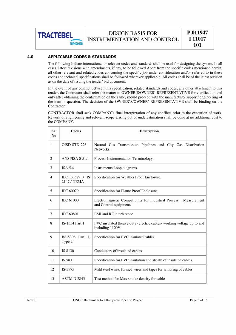
4.0 APPLICABLE CODES & STANDARDS
The following Indian/ international or relevant codes and standards shall be used for designing the system. In all
cases, latest revisions with amendments, if any, to be followed Apart from the specific codes mentioned herein,
all other relevant and related codes concerning the specific job under consideration and/or referred to in these
codes and technical specifications shall be followed wherever applicable. All codes shall be of the latest revision
as on the date of issuing the tender/ bid document.
In the event of any conflict between this specification, related standards and codes, any other attachment to this
tender, the Contractor shall refer the matter to OWNER’S/OWNER’ REPRESENTATIVE for clarification and
only after obtaining the confirmation on the same, should proceed with the manufacture/ supply / engineering of
the item in question. The decision of the OWNER’S/OWNER’ REPRESENTATIVE shall be binding on the
Contractor.
CONTRACTOR shall seek COMPANY's final interpretation of any conflicts prior to the execution of work.
Rework of engineering and relevant scope arising out of underestimation shall be done at no additional cost to
the COMPANY.
Sr.
No
Codes Description
1 OISD-STD-226 Natural Gas Transmission Pipelines and City Gas Distribution
Networks.
2 ANSI/ISA S 51.1 Process Instrumentation Terminology.
3 ISA 5.4 Instruments Loop diagrams.
4 IEC 60529 / IS
2147 / NEMA
Specification for Weather Proof Enclosure.
5 IEC 60079 Specification for Flame Proof Enclosure
6 IEC 61000 Electromagnetic Compatibility for Industrial Process Measurement
and Control equipment.
7 IEC 60801 EMI and RF interference
8 IS-1554 Part 1 PVC insulated (heavy duty) electric cables- working voltage up to and
including 1100V.
9 BS-5308 Part 1,
Type 2
Specification for PVC insulated cables.
10 IS 8130 Conductors of insulated cables
11 IS 5831 Specification for PVC insulation and sheath of insulated cables.
12 IS-3975 Mild steel wires, formed wires and tapes for armoring of cables.
13 ASTM D 2843 Test method for Max smoke density for cable

DESIGN BASIS FOR
INSTRUMENTATION AND CONTROL
P.011947
I 11017
101
Rev. 0 ONGC Bantumalli to Ullamparru Pipeline Project Page 4 of 16
Sr.
No
Codes Description
14 ASTM D 2863 Test method for measuring of Temp and O2 Index.
15 IEC 60754 Acid generation test
16 IEC-332-3 Part 3 Tests on bunched wires and cables.
17 BS 6121, EN
50262
Cable gland – flame proof Ex”d” or Exe increase safety.
18 DIN- 50049 Document on Material Testing.
19 ASME PTC 19.3 Temperature Measurement- calculation of natural frequency.
20 IEC 751 / DIN
43760
RTD
21 IEC 584/DIN
43710 / ANSI
MC 96.1
Thermocouple
22 ISO 5167 Measurement of fluid flow by means of orifice plates, Nozzles and
Venturi tube inserted in filled piping circular profile.
23 ASME B 16.36 Orifice flange with flange pressure tap.
24 ASME B16.5 Pipe line flanges and flanged fittings
25 API-RP-520 Sizing and selection of safety relief valves.
26 IS 3624 / BS EN
837
Pressure gauge
27 AGA 3 Orifice flow measurement
28 AGA 9 Ultrasonic flow measurement
29 AGA 8 Compressibility factor of natural gas.
30 AGA 10 Calculation of Speed of sound in Natural gas
31 API Spec 6A Valve design methodology
32 API 6D Petroleum and natural gas valve
33 ISA 75.01 Flow equation for sizing of control valve

DESIGN BASIS FOR
INSTRUMENTATION AND CONTROL
P.011947
I 11017
101
Rev. 0 ONGC Bantumalli to Ullamparru Pipeline Project Page 5 of 16
Sr.
No
Codes Description
34 ISA 75.02 Testing of CV rating , control valve capacity test
35 ISA 75.05 Control valve terminology
36 ISA 71.07 Laboratory measurement of aerodynamic noise generated by control
valves.
37 FCI 70.2/ANSI B
16.104
Control valve seat leakage.
38 ASME/ANSI B
16.34
Valves-Flanged, Threaded and welding end.
39 IEEE 802 The LAN standards.
40 IEC-60870-5-
104/101 SCADA Communication protocol
41 DNP 3 (TCP/IP),
DNP 3 (Modbus) SCADA Communication protocol
42 IEC 61131 RTU, remote terminal unit
43 IEC 60870-5-101 Modbus serial RS232/Rs485
44 ISA 5.3-1983 Graphic Symbols for Distributed Control/Shared Display
Instrumentation, Logic, and Computer Systems.
45 ISA-5.5-1985 Graphic Symbols for Process Displays
46 TIA/EIA 58 Communication standard
47 OISD Oil Industry Safety Directorate Government of India
47.1 OISD 118 Layouts for Oil & Gas installations
47.2 OISD 152 Safety Instrumentation for Process System in Hydrocarbon Industry
47.3 OISD 153 Maintenance and Inspection of Safety Instrumentation in Hydrocarbon
Industry
47.4 OISD 163 Process Control Room Safety
47.5 OISD 195 Safety in Design, Operation, Inspection and Maintenance of
Hydrocarbon Gas Compressor stations and Terminals

DESIGN BASIS FOR
INSTRUMENTATION AND CONTROL
P.011947
I 11017
101
Rev. 0 ONGC Bantumalli to Ullamparru Pipeline Project Page 6 of 16
Sr.
No
Codes Description
48 NFPA National Fire Protection Association
48.1 NFPA-70 National Electrical Code
48.2 NFPA-497 Electrical installation, classification of Class1 & Class 2 hazardous
locations
48.3 NFPA-101 Life Safety Code
48.4 NFPA 325M Fire Hazard Properties of Flammable Liquids, Gases, and Volatile
Solids for LEL of Gases
49 PNGRB Technical & safety standards statutory requirements for natural gas
pipelines.
5.0 STATUTORY APPROVALS / CERTIFICATES (AFTER GETTING ORDER)
5.1 The bidder shall be responsible for obtaining all statutory approvals, as applicable for all instruments and
instrumentation systems.
5.2 Equipment / instrument / systems located in electrically hazardous areas shall be certified for use by statutory
authorities for their use in the area of their installation. In general, following certification shall be provided by
the bidder.
a. For all flameproof equipment / instrument / systems, which are manufactured abroad (outside India)
certification by any approving authority like BASEFA, FM, UL, PTB, LCIE, CENELEC etc. shall be
required.
b. For all flameproof equipment / instrument / systems manufactured locally (within India), certification shall
be carried out by any of the approved testing houses – Central Mining Research Institute (CMRI) etc. The
manufacturer shall hold a valid Bureau of Indian Standards (BIS) license.
c. Approval certificate from Chief Controller of Explosives (CCE) or Petroleum and Explosive Safety
organisation (PESO) is mandatory for all electronic / electrical instruments / equipment to be installed in
India, irrespective of country of origin.
6.0 ENGINEERING UNITS
a
Flow
Gas Sm³/hr / MMSCMD
Mass flow kg/hr.
Volumetric flow m³ / hr.
b Pressure Barg
c Temperature °C.
d Level %.
7.0 INSTRUMENTATION EARTHING SYSTEM
7.1 General

DESIGN BASIS FOR
INSTRUMENTATION AND CONTROL
P.011947
I 11017
101
Rev. 0 ONGC Bantumalli to Ullamparru Pipeline Project Page 7 of 16
The earthing for electrical earth and electronic earth shall be arranged to provide safe installations, and to
prevent electrical interference with their operation.
All earthing and shielding shall comply with the requirements of all standards applicable to the area
classification in which the equipment is installed.
7.2 Instrument cases, panels. etc.
a) All parts of field installations, e.g. Cable trays, junction boxes, local panels, instrument housings,
conduits, cable armour, etc.., shall be effectively grounded via the general plant earthing system.
b) Earthing of cable trays shall be in accordance with the IEC requirements as a minimum.
7.3 Each supplied instrument, local control panel, fire detection panel, gas detection panel system shall have
earthing lugs with their frames. All these lugs/ strips shall properly have secured to the electrical earthing bus.
7.4 All system grounds of various cards and equipment, shields of signals (instrument) cables shall connect to
system ground bus, which is electrically isolated from the AC mains earthing bus. The equipment shall provide
separate earthing strip for the same. The system ground bus shall have independent ground buses through
insulated wires.
a) System grounding (earth resistance less than 1 ohm)
b) Frame and AC mains grounding (earth resistance less than 5 ohms)
7.5 Lightning protection
Where connections between control systems and/or distant equipment may be affected by lightning surges or by
other inducted high voltages, the connection cables shall be equipped with over-voltage arresters.
8.0 FIELD INSTRUMENTS SPECIFICATION
8.1 PT shall be intrinsically safe electronic SMART type transmitters compatible with HART protocol of latest
version. All transmitters shall be 2-wire type with integral digital indicator. Enclosures shall be Weather proof
to IP 65. Pressure transmitters shall be capacitance / piezo-resistance type. Process entry and cable entry shall be
½” NPT (F). Accuracy of Pressure transmitter shall be ± 0.075% of span. Transmitters O/P shall be 4-20 mA
DC. Surge protection device shall be provided with the transmitter to protect the instruments from lightning or
any kind of hazardous surge
8.2 Temp transmitters shall be intrinsically safe electronic smart type transmitters compatible with HART protocol
of latest version. Transmitters shall be 2-wire type with integral digital indicator and dual compartment type.
Enclosures shall be Weather proof to IP 65. Temp sensor entry and output cable entry shall be ½” NPT (F).
Transmitter shall be ± 0.18% of FSD. Transmitters O/P shall be 4-20 mA DC. Transmitters shall be provided
with output meters (LCD in Engineering Unit). Surge protection device shall be provided with the transmitter to
protect the instruments from lightning or any kind of hazardous surge
8.3 A universal type Hand Held Configurators with carrying case and charger shall be provided for this project.
8.4 PG shall be Direct-mounting type having element of bourdon tube and dial size of 150 mm. It shall have
shatterproof glass. Connection shall be ½” NPT (M) from bottom. Enclosure shall be weather proof to IP65.
Protection shall be 130% over range. Accuracy shall be ±1% of FSD. PG shall have blown out disc facility. For
higher pressure applications (above 60 Barg), it shall be solid front type.
8.5 Temperature element shall be immersion type and skin type with temperature transmitter. Skin type element
shall be provided at vent line as per P&ID along weld pad and associated accessories
RTDs are 4 wire type and element shall be Pt100 as per DIN/IEC, accuracy class A and thermowell’s
immersion length shall be suitable for the line size. All RTDs shall have duplex elements. RTDs sheath OD
shall be 10 mm and material SS 316. Cable entry shall be ½” NPT (F). Enclosure shall be WP to IP-65. All
RTD shall be supplied with thermowell. The thermowell shall be flanged type.

DESIGN BASIS FOR
INSTRUMENTATION AND CONTROL
P.011947
I 11017
101
Rev. 0 ONGC Bantumalli to Ullamparru Pipeline Project Page 8 of 16
8.6 Differential pressure switch enclosure shall be Weather proof IP65, process entry from Bottom /side entry,
Process connection ½” NPT (F), Pressure element shall be Diaphragm (material SS316), Setting adjustable,
Switch DPDT switch, Cable entry ½” NPT (F).
8.7 SOLENOID VALVES
The solenoid valve shall be of 3 way, universal type with manual operation facility. The body and internals shall
be of SS 316. Valve shall be made leak proof with 'O' ring seals. The solenoid valve shall have weather proof
and intrinsically safe, suitable for the hazardous area. The power supply shall be 24VDC. Instrument air/natural
gas supply connection shall be 1/4" or 1/ 2” NPT (F). Solenoid valve shall be provided with integral junction
box, having 1/2" NPT (F) cable entry. Surge suppression diodes shall be provided across the coil. Coil class
shall be Class “F”
8.8 VALVE POSITION SWITCH
Valve position switches for open / close position indication shall be of sealed micro type lever operated. The
switch shall be of DPDT type with contact rating 24V DC, 2 Amp suitable for inductive load. The switch
enclosure shall be dia cast aluminum, weather proof and intrinsically safe suitable for hazardous area. Valve
position switch shall be provided with integral junction box having 2 nos. of 1/2" NPT (F) cable entries.
8.9 All instruments impulse line (1/2” tubes) shall be consist of tubing and piping. The impulse tube shall be SS316
and all the impulse pipes shall be CS/LTCS. Compressed type ferrule fitting such as ½” NPT (M) to NPT (F)
fittings (male/female connectors), ½” tee, ½” union including ½” isolation needle/ball valves & other
accessories shall be according piping material.
9.0 INSTRUMENT CABLES
9.1 1P X 1.5 mm², 2P X 1.5mm², 1Q X 1.5mm², 6Qx0.5mm², 6P X 0.5mm², 12P X 0.5mm², 1T X 1.5mm² and 12T
X 1.5mm²cables shall generally be used for connecting instruments to local control panel through junction box.
9.2 All instrument cables shall be FRLS. Cables shall be individually and overall shielded for analog signals and
overall shielded for digital signals. All cables shall be galvanized steel wire type armour as per IS-1554 Part 1.
9.3 For power cables refer electrical specification.
9.4 CABLE GLANDS
Cable gland shall be provided for all the above mentioned cables both at field instrument, junction boxes and
local control panel.
Instrument cable gland shall be ½” NPTM insulating glands double compression type, weather proof (WP) IP
65 in field instrument side only for underground instruments tapping to protect the CP current drainage.
Except that, all other shall be standard metallic gland. All cables glands shall be of nickel-plated brass WP IP65
and they shall be double compression type suitable for armoured cables.
Flame proof Ex (d) glands in hazardous area shall be supplied and along with Ex (d) certification.
9.5 CABLE TRAYS AND CABLE DUCTS
All branch cables/trench cable shall run on cable trays.
These cable trays shall be made out of galvanized iron-perforated type of 2.5 mm thickness. These trays are
supported with
Suitable clamps shall be supplied for binding the cables/tubes at every 500 mm interval. All the cable/tubes
shall be laid in trench, false flooring/ ceiling trays, instrument support structures and supported with 50 mm x 50
mm angles as a minimum.
Maximum width of the cable tray shall be 600mm and height 50mm, 75mm or 100mm as applicable. 25% spare
capacity shall be provided for cable trays.

DESIGN BASIS FOR
INSTRUMENTATION AND CONTROL
P.011947
I 11017
101
Rev. 0 ONGC Bantumalli to Ullamparru Pipeline Project Page 9 of 16
9.6 JUNCTION BOXES
Junction boxes shall be provided for intrinsically safe and non-intrinsically safe instruments also as required for
packages such as gas detection system, corrosion monitoring system, fire detection system etc.
For non-intrinsic safe signals, junction box shall be explosion proof to Exd. IIA/IIB, T3 and weather proof to IP
65 and made up of dia cast aluminium.
For intrinsic safe signals, junction box shall be weather proof to IP 65 made up of di-cast aluminium.
9.7 MUTICABLE TRANSIT
MCT shall be provided at cable entry to control room from field (hazardous area). The MCT frames shall be of
standard modular variable diameter RGB type, steel construction MCT frames shall be suitable to withstand
blast intensity. The MCT shall be supplied complete with insert blocks, spare blocks, stay plates, end packing
etc. The MCT shall be sized considering 20% spares for each cable size/cable OD. Intrinsically safe cables and
non-intrinsically cables shall be suitably separated within the MCT frame. For HT cables, LT cables/power
cables and other electrical cables separate MCT frame shall be provided. Spare space shall be filled with
dummy block of suitable size.
10.0 LOCAL CONTROL PANEL
10.1 The panel shall be self-standing/wall mounted supplied in dust & vermin proof, floor mounted, sheet steel
enclosure. Minimum degree of protection for panel shall be IP 42 as per IS-2147.
10.2 Enclosure shall be fabricated with cold rolled closed annealed (CRCA) sheet steel of minimum thickness 1.6
mm and gland plate thickness shall be 3 mm.
10.3 Panel shall have single front door & double rear door. Mounting height of equipment/components inside the
floor mounted panel requiring operation and observation shall not be less than 300 mm and higher than 1600
mm. Tentative Size of self-standing cabinet shall be 2100 (including 100 mm base frame) (H) x 1000 (W) x 800
(D) mm and for wall mounted as per vendor standard.
10.4 Panel shall be liberally designed. All components shall be so mounted that they are easily accessible for
inspection & maintenance.
10.5 Color of panel: RAL 7035 for the panel exterior & interior and black for the base frame.
10.6 Panel shall have door switch, cable glands, MCBs, 5A power supply socket, Hooter, Reset and acknowledge
push button, panel light, lugs, exhaust fan, digital indicator, lamp, analog & digital barriers/Isolator, repeater/
Relay, pressure and temp indicator as minimum accessories.
11.0 FIRE DETECTION SYSTEM
11.1 Conventional type fire detection system shall be comprised of multisensory detectors, includes optical /Photo
electric type smoke detectors and heat detectors based on rate of raised. Multi sensor detectors shall be installed
in the miscellaneous rooms like electrical room, control room/equipment room battery room, false ceiling, and
false flooring as applicable of the different stations along the pipeline network. Two detectors shall be
connected in loop to avoid false notification.
11.2 Optical/Photo electric type smoke detectors for timely detection of smoke/fire. Smoke detectors installed above
the false ceiling and below false flooring wherever applicable in order to sense the fire occurred in the electrical
wiring & fittings etc. The smoke detectors above the false ceiling and below false flooring are not be visible,
these detectors shall be fitted with remote Response Indicators located below the false ceiling, and above false
flooring (on adjacent wall) which shall glow in the event of actuation of these detectors.
11.3 On the alarming, two red flashlights located in the Control Room and in the guard room at site and two horns
one inside and other outside shall be actuated at the same time.

DESIGN BASIS FOR
INSTRUMENTATION AND CONTROL
P.011947
I 11017
101
Rev. 0 ONGC Bantumalli to Ullamparru Pipeline Project Page 10 of 16
11.4 A break glass unit (BGU) shall be installed at the outer side of each rooms and in field wherever feasible
(decided during engineering stage) for manual actuation of the fire alarm.
11.5 When a detector shall be in alarm condition, the information shall be sent to the central unit and the same signal
shall be sent to SCADA through RTU. The alarm situation of the detector shall remain “ON” until a manual
reset device is activated on the central unit. An indicating LED shall permit the direct identification of the
detector that is the cause of alarm.
11.6 The fire control panel shall derive its power from a 48V DC main UPS, which shall be converted to require
voltage (DC) level by the contractor inside the panel. The fire control panel shall provide the required power to
the sensors and accessories and shall monitor the zonal circuits for open and short circuit faults. The fire control
panel shall also be provided with a secondary power source comprising two nos. of Maintenance free batteries,
which automatically takes over the system in the event of 48 V DC UPS power failure to the panel.
11.7 Contacts used in intrinsically safe circuit shall be gold plated. All electronic circuits used in the system shall be
free from the effects of any RF interference.
11.8 Fire detection panel shall be wall mounted for all unmanned station. Size of the wall mounted panel as per the
vendor standard. Fire detection panel shall be floor mounted free-standing type for manned stations.
11.9 Fire detection system shall be suitably hooked up with CO2/Clean agent fire suppression system for
auto/manual flooding in control room/equipment room and electrical.
11.10 Field mounted Electrical Operated Siren with audible range of min 1 KM integrated with fire detection system.
12.0 GAS DETECTION SYSTEM
12.1 The addressable type hydrocarbon gas detection system shall be comprised of flame proof flame proof point gas
detectors (PGD) with integral type digital indicator and main control unit at control room/equipment room.
12.2 Point gas detectors shall be “IR” type. PGD shall be mounted at the possible leakage point and near equipment
and tap-off node.
12.3 The high and high high gas concentrations and a failure/default state shall be detected and signalized by the
control unit.
12.4 Gas detectors output shall be digital communication. Control unit shall be interface with RTU/SCADA system
on RS 485/RS232
12.5 Main control unit shall be wall mounted. Size of the panel as per the vendor standard.
13.0 OPTICAL FIBRE CABLE
13.1 The optical fiber cable shall be armored comprising of 24 nos. single mode fibers comprising of 18 fibers ITU-
T-G-652 and 6 fibers ITU-T-G-655, suitable for working in 1550 / 1310 nm wavelength region suitable for
laying through silicon coated HDPE duct. The cable shall be fire retardant, chemical resistant, termite & rodent
proof and moisture proof. The drum length shall be 4 km.
13.2 OFC shall be laid inside a permanently lubricated HDPE pipe (Dia 50mm) adjacent to pipe.
13.3 Total length of OFC shall be pipeline length including minimum loop length upto the control room at each
station and loop length in inspection chamber + 1 km extra
13.4 Single Mode Optical Fiber, Fully ITU T rec. G652 Oct 2000, IEC 60793-1 AND Telecordia GR – 20 core
compliant
13.5 Inspection chambers of required dimensions shall be provided at every 4 Km intervals along the pipeline route.
The 24 F splice enclosure shall be placed in the inspection chambers after splicing of the Optical Fibre cable at
every 4 Km intervals along the optical fibre route.

DESIGN BASIS FOR
INSTRUMENTATION AND CONTROL
P.011947
I 11017
101
Rev. 0 ONGC Bantumalli to Ullamparru Pipeline Project Page 11 of 16
13.6 Route markers of required dimensions shall be provided at every Kilometer along the pipeline route. The route
markers shall be also placed at top of every inspection chamber, crossings etc.
13.7 Additionally, at each jointing location, Electronic locating system suitable for field use to locate underground-
buried OFC joint locations. The system shall consist of-
a) Electronic marker (to be buried underground along-with OFC joints)
b) Marker locator (including probe & locator electronics)
14.0 PLB HDPE DUCT
14.1 The PLB – HDPE Duct shall consist of two concentric layers, the outer layer being HDPE; co-extruded with an
inner layer of solid permanent lubricant, to reduce the internal co-efficient of friction (ICF). The lubricant shall
be of a solid layer of uniform thickness so formulated to provide a permanent, low friction boundary layer
between the inner surface of the duct & optical fiber cable. The lubricant layer shall be clearly visible in cross-
section, concentric with the outer layer.
14.2 PLB HDPE ducts shall be suitable for installation of underground unarmored optical fiber cables (OFC) by
blowing techniques. The life expectancy of these ducts shall not be less than 30 years.
14.3 PLB-HDPE duct shall be laid throughout the pipeline and stations. Additional PLB-HDPE duct shall be laid at
all crossing, river, nalah, culvert, road/railway, canal etc. inside the separate 6” CS casing pipes.
14.4 Total quantity of HDPE duct shall be pipeline length including the minimum loop length at each station + 1 km
extra length. Extra length shall be used for hooking up of OFC to telecom unit at all stations.
15.0 CORROSIVE MONITORING SYSTEM
15.1 The electrical resistance (ER) type probes and coupons to be installed at the stations as mentioned above shall
be retrievable from the line under pressure. The probes and coupons shall be flush mounted on the pipeline. All
materials in contact with fluid shall be in accordance with NACE Standard MR-01-75. Pipeline inlet pressure
may vary according to pipeline pressure drop due to different flow rates. The corrosion monitoring system shall
be suitable for operation under this fluctuating pressure conditions.
15.2 Each probe shall be connected to a transmitter (2 wire systems) to give an output of 4-20 mA, proportional to
corrosion rate.
15.3 Local monitoring equipment of CMS shall be mounted in the LOCAL CONTROL PANLE.
15.4 Barrier, display unit, terminal blocks etc shall be provided in the LCP cabinet. Single shall be repeated through
dual output channel repeater or barrier to provide the independent signals to RTU as well local indicator.
16.0 TELECOMMUNICATION SYSTEM
16.1 Optical Fiber based SDH Communications System (STM-4). The flat ring based on dual optical fiber pair, shall
be formed with all the stations on gas pipeline. These STM-1 nodes shall be configured as ADM-node. The ring
is based on a sequential network topology with a redundant path. The proposed system shall use the latest
technological advancements in SDH networks such as Virtual Concatenation (VCAT) and Link Capacity
Adjustment Scheme (LCAS). SNCP protection should be supported. The equipment shall be upgradeable to
STM-4 without any changes in the backplane.
16.2 Providing high speed data communication for SCADA. Direct dialing facility between the stations shall be
provided through EOW lines. Providing high speed data communication network management system for
telecom, as required.
16.3 NMS of SDH systems
Existing NMS shall be used for integration.

DESIGN BASIS FOR
INSTRUMENTATION AND CONTROL
P.011947
I 11017
101
Rev. 0 ONGC Bantumalli to Ullamparru Pipeline Project Page 12 of 16
17.0 IP BASED VIDEO SURVEILLANCE SYSTEM (CCTV)
17.1 Video Surveillance system shall be provided at SV stations which includes one number fixed colour camera and
one number PTZ colour camera. The CCTV shall work on IP protocol.
17.2 Proposed CCTV system shall be an open standard based integrated system with IP network centric functional
and management architecture aimed at providing high-speed manual/automatic operation for best performance.
17.3 CCTV cameras are compliance to surveillance industry open standard protocol called ONVIF that allows
cameras to communicate with each other and with network recording devices.
18.0 REMOTE TERMINAL UNITS (RTU)
18.1 RTU shall have dual Ethernet ports (configurable independently) for TCP/IP communication with SCADA
system on multi-dropped environment. Both the communication port should support Class 0, 1, 2 & 3 polling
from SCADA independently.
18.2 RTU should compatible with Centralized SCADA system. The RTU should support DNP 3.0 protocols for
communication with SCADA Servers and MODBUS (RTU) for communication with IEDs.
18.3 The ports for communication with Servers shall be available on a separate card than the card being used for
interfacing with IEDs. Serial ports available at serial card should be independently and individually configurable
in all respect.
18.4 All interfacing cables from RTU to IEDs shall be armoured. All communication cables from RTU to Telecom
equipment shall be armoured
18.5 The RTUs shall be microprocessor based programmable units with both erasable ROM and RAM memory.
Each of the RTUs shall have its own processor, memory, power supply unit & communication processors and
I/O cards complete in all respects. All RTUs shall be modular and from the same model product line with
identical capabilities.
18.6 The complete RTUs shall be supplied with all its components including the cabinets.
18.7 The I/O cards shall not be combined for the functionalities i.e. each card shall perform dedicated functionality
w.r.t analog input, analog output, digital input, digital output
18.8 All the supplied RTUs shall be with same make & model no., differing only in number of RTU I/O cards.
18.9 RTU should have surge/lightening protection for 24V input power supply and all Ethernet, Serial and
Communication ports. All field signals interfacing with RTU shall be surge protected.
18.10 The Digital Output shall be configured for pulse duration. No separate program or logic shall be acceptable at
RTU end. On RTU restart/ power failure, RTU shall not reset the output circuit, shall not generate false control
signal and shall necessarily cancel all pending control signal.
18.11 AI, DI and DO card of the RTU shall be as per actual requirement (in addition to spares) The AO card (If any)
shall have minimum 4 I/O points. The serial card shall have minimum 4 ports.
18.12 RTU configurator software licenses shall be preferred in software (software key) form instead of hardware
(dongle). Multiuser software licenses shall be provided.
18.13 RTU shall have diagnostic provision without uploading /downloading RTU configuration to PC/laptop.
18.14 RTU configurator tool shall be compatible with 64-bit O.S i.e. Minimum Window 7 Basic & Enterprise and
above, Window Server 2008 R2 Standard & Enterprise edition and above. In case RTU software installation in
PC or server requires additional software like dot NET, java etc, it should be declared and provided by RTU
Vendor.
18.15 RTU configuration and diagnostic tool should be able to connect to RTU remotely over TCP/IP even during
polling from SCADA FEP on same TCP/IP.

DESIGN BASIS FOR
INSTRUMENTATION AND CONTROL
P.011947
I 11017
101
Rev. 0 ONGC Bantumalli to Ullamparru Pipeline Project Page 13 of 16
18.16 RTU shall preferably have provision of authentication while connecting configuration and diagnostic tool
should use authentication like username and password.
RTU configuration and diagnostic tool should preferably have provision to warm restart of RTU.
18.17 RTU login shall be authorized using User Id and Login to do any configuration changes. RTU configurator /
diagnostic software shall have the following provision:
• Index of all I/O along with present real time field data to be available in diagnostic software table/window.
• All RTU cards, serial ports and communications channels health points are to be configured in RTU and
DNP index of same are to be reflected in I/O list.
18.18 The RTUs shall comprise the following subsystems:
• Central processor with system software
• Analogue input
• Contact (digital) input
• Analogue output
• Contact (digital) output
• Communications (Redundant)
• Serial ports
• Power supply (Redundant)
• Diagnostic (on-line from SMCS and off-line diagnostics)
18.19 RTU Features
The RTU sub-system shall support the following:
a) Scanning of Input and Output
b) Discrete control with interlocks, supporting check before executes and control time out feature.
c) Derivation of calculated digital points based on logical arithmetic functions (AND, OR, NOT).
d) Derivation of calculated analog points based on arithmetic functions and driving external hardware.
e) Calculation shall be performed in RTU in engineering units with 16bit floating point accuracy.
f) Interfacing with PLC systems/third party systems for data.
g) Separate database for separate polling sequences in multiple directions.
h) Integrated Web based HMI for remote supervision via web browser over SCADA network.
i) DNP 3.0 over TCP/IP protocol or IEC 60870-5-104 protocol for communicating with the Master Control
station. However, the following standard communication protocols shall also be supported by the RTUs:-
DNP 3.0 or IEC 60870-5-101, Modbus TCP/IP or Modbus RS485.
j) Full RTU diagnostics shall be available in the SCADA Engineering Workstations.
k) Automatic time synchronization of Remote telemetry units shall be implemented from MCS.
18.20 The RTUs shall have a self-diagnostic feature and software watchdog timer devices to monitor & report the
healthiness of CPU, memory, power supply, comm. interfaces and Input/ Output modules at the local level.

DESIGN BASIS FOR
INSTRUMENTATION AND CONTROL
P.011947
I 11017
101
Rev. 0 ONGC Bantumalli to Ullamparru Pipeline Project Page 14 of 16
18.21 RTU shall be capable of updating process parameters data and configuration data in its own built-in memory.
Time stamping of all field values at RTU level. In the event of failure or break of communication link between
Master Control station and RTU, the RTU shall continue to scan all parameters and update its database.
18.22 For long term communication outage with Master control station; the RTUs shall be designed to scan the field
and store in the memory a minimum of 7000time stamped events (analog, digital, diagnostics etc) during the
period of communication outage for retrieval by SMCS subsequently.
18.23 The RTU memory sizing shall be adequate to meet the above requirement. In case additional memory cards are
required to meet this requirement, same shall be provided by the vendor. RTUs buffer shall be circular buffer
with new events replacing old events.
18.24 RTU shall support communication protocol supporting report by exception to prevent unnecessary data
communication when the data is not changing.
18.25 It shall have feature of connecting a pluggable Programmable Diagnostic Test unit (PDT) with keyboard &
monitors diagnostic and programming aid to trouble shoot and configuration tool for RTU and I/O boards. It
shall be possible to exercise all the functions of the RTU without disconnecting the RTU from process.
19.0 METERING SYSTEM
19.1 Metering skid shall be consisted of one working and one standby stream. Multipath Ultrasonic (minimum 4
paths) flow meters along with flow computers according to AGA-9 & AGA10. The flow computers are
connected directly to online gas chromatographs for flow computation, super compressibility, calorific values
etc. Metering system supplier shall supply flow computer along with all required hardware’s and software’s,
which shall be installed in the metering panel. Flow meters shall be calibrated at high pressure as per the
standard and in approved lab.
19.2 Accuracy of Ultrasonic flow meters shall not be degraded beyond ±0.3% even if one path fails and repeatability
shall not be degraded beyond ±0.1% of reading.
19.3 Metering panel shall have flow computer, printer, GC controller, power supply unit, Barriers isolators,
repeaters, other panel accessories etc. as required.
19.4 RTDs are 4 wire type and element shall be Pt100 as per DIN 43760 & accuracy class A and thermowell’s
immersion length shall be suitable for the line size. All RTDs shall have duplex elements. RTDs sheath OD
shall be 8 mm and material SS 316. Cable entry shall be ½” NPT (F). Enclosure shall be WP to IP-65. All
RTD shall be supplied with flange type thermowell.
19.5 PT shall be intrinsically safe electronic SMART type transmitters compatible with HART protocol of latest
version. Transmitter shall have dual compartment housing. Transmitters shall be 2-wire type with integral
digital indicator. Enclosures shall be Weather proof to IP 65. Pressure transmitters shall be capacitance / piezo-
resistance type. Process entry and cable entry shall be ½” NPT (F). Accuracy of Pressure transmitter shall be ±
0.075% of span. Transmitters O/P shall be 4-20 mA DC. Surge protection device shall be provided with the
transmitter to protect the instruments from lightning or any kind of hazardous surge
19.6 Flow Computer
a) The stream flow computers shall be microprocessor based, with keypad and alphanumeric display with
AGA firmware for flow measurement. The stream flow computers shall be linked to the SCADA for
providing the flow measurements of the individual stream runs and related process variables.
b) Flow computers according to AGA 8 & 9. The flow computers are connected directly to online gas
chromatographs for flow computation, super compressibility, calorific values etc.
c) Each of the flow streams shall be provided with a dedicated flow computer. The flow computer shall access
the flow meter data and diagnostic data through RS 485.

DESIGN BASIS FOR
INSTRUMENTATION AND CONTROL
P.011947
I 11017
101
Rev. 0 ONGC Bantumalli to Ullamparru Pipeline Project Page 15 of 16
d) The stream flow computers shall compute and display the instantaneous and totalised flow rate for each
stream corrected for pressure and temperature variations. The stream flow computers receive data from the
Gas chromatograph (as applicable) for calculation of the Gross Heating Value (GHV) and Net Heating
Value (NHV) of the gas.
e) Flow computer shall be provided with facilitate for manual entry of data like atmospheric pressure, GC
valves etc. also privilege for selectable units.
f) Flow computers shall be in safe (non-hazardous) control room. However, the entire system shall be
designed for non-air-conditioned environment also. It shall be suitable for ambient condition (i.e.
temperature 4 to 55°C and relative humidity 100%.
20.0 GAS CHROMATOGRAPH
a) The Gas Chromatograph (GC) shall consist of microcomputer controller, GC oven and an integral sample
conditioning system. The GC system complies with the criteria set forth in ASTM-1945, and GPA-2261.
b) The composition of the gas shall be continuously analysed by an online gas chromatograph located on the
skid. The chromatograph shall analyse the C1 thru’ C6+ components in the gas as well as CO2 and N2.
c) The chromatograph shall be complete with sample handling system located outdoor in a 3 sided shelter,
mounted on a skid. The detector shall be TCD (Thermal Conductivity Detector) type and cycle time shall
not exceed 10 minutes.
d) The Chromatograph controller shall be installed in metering cabinet. The signals corresponding to the
components shall be transmitted on serial link to the stream flow computers. GC shall provide online
calibration facility. Necessary carrier gas and calibration gas cylinders shall be provided as part of the
chromatograph system.
e) Three each carrier gas cylinders and two each calibration gas cylinders shall be installed in a rack with
stainless steel safety retaining chains, connected for use with stainless steel tubing. Cylinder shall be colour
coded and identified with contents. Cylinders shall be supplied complete with safety-pattern bottle pressure
regulators and gauges with automatic changeover facilities.
f) Gas chromatograph controller shall have four number of communication ports (RS 485) for communication
with both stream flow computer and RTU and one number spare
20.1 Sample Conditioning System
a) The gas chromatograph shall be supplied complete with all samples conditioning and tubing.
b) The gas chromatograph shall be supplied complete with a dual helium carrier gas system including
regulating system and tubing such that carrier gas supply bottles can be changed without interrupting the
carrier gas supply. The vendor shall supply three each pre-filled helium carrier gas cylinders (helium to be
99.995% pure with less than 5 ppm water and 5 ppm hydrocarbons). The carrier gas must be certified by a
recognized laboratory and must be of ultra-purity.
21.0 FILTRATION SKID
a) Each stream of filtration skid consists of one filter and its respective instrumentation.
b) One "filtration skid" shall be provided with one running and one standby (1+1) filtering lines comprising all
the material required for removing the solid and liquid particles larger than 5 micron from the gas.
c) The filter shall be of the single chamber coalescing type.
d) The discrete and analog signals from the various instruments installed on the skid are connected to the
Metering Panel.

DESIGN BASIS FOR
INSTRUMENTATION AND CONTROL
P.011947
I 11017
101
Rev. 0 ONGC Bantumalli to Ullamparru Pipeline Project Page 16 of 16
22.0 PRESSURE REDUCTION SKID
a) Pressure let down skid, one running and one standby concept (1+1), as per P&ID.
b) Pressure let down skid consist of active & monitor self-regulated pressure control valve, slam shut off
valve, creep relief valve and pressure gauge.
c) The pressure reduction skid is used primarily to control the outlet pressure. Inlet to the PRS is from the
Metering Skid. This is achieved with active and monitor pressure Control Valve mounted in series and
SSV.
d) The Skid has one Slam Shut-off valves (SSV), used for Safety Purpose. Its function is to close the stream if
both the Control Valve fails.
e) Two control valves shall be connected in the series. First is Active control valve and second is monitor
control valve. In the event of failure of Active Control Valve, monitor control valve shall takes the control.
f) The Active Control Valve normally controls Pressure. This works as override control and at any point of
time during operation, if Flow increases above its Flow set point, Control Valve shall start controlling Flow
overriding its normal operation of Pressure Control.
g) SSV shall be tripped on high high pressure and low low pressure.
23.0 H2S AND MOISTURE ANALYZER
Field mounted single/dual compartment single stream H2S and moisture monitoring system. Ex-Proof & WP IP
66 electronic enclosure shall be provided. H2S and Moisture system along with controller and sample
conditioning system. Detectors shall be IR absorption spectroscopy QCL/TDL type. Measurement time shall be
less than one minute. Repeatability shall be ±1% and power supply 230 V AC. Output shall be 4-20mA and
digital communication (RS 485).
H2S and Moisture analyser shall be integrated with metering HMI system. These shall also be interfaced with
RTU on RS 485

MATERIAL REQUISITION P.011947
I-11071
101
ONGC BANTUMILLI TO ULLAMPARU PIPELINE KG
BASIN
TRACTEBEL ENGINEERING PVT. LTD.
MATERIAL REQUISITION
DOC. NO. P.011947 I 11071 101
0 01.05.2018 Issued for Procurement AS SK SKH
REV. DATE Subject of Revision Prepared By Checked By Approved By

MATERIAL REQUISITION P.011947
I 11071
101
Rev.0 ONGC Bantumalli to Ullamparru pipeline Page 1 of 10
A. DESCRIPTION OF GOODS AND/OR SERVICES
Item Description Unit Quantity Remark
A SUPPLY
1 Supply of Pressure Transmitter along with 2 valve manifolds
with all accessories as per Data sheet, PTS-Instrumentation with
appendices (P.011947-I-11097-101) and Scope of Work C&I
(P.011947-I-11075-101)
Nos. 6
2
Supply of Pressure gauge including high range and low range
along with 2 valve manifolds, gauge saver with all accessories
as per Data sheet, PTS-Instrumentation with appendices
(P.011947-I-11097-101) and Scope of Work C&I (P.011947-I-
11075-101).
Nos. 16
3
Supply of temperature element (RTD) along with flanged
thermowell mounted for underground and above ground
pipeline with all accessories as per Data sheet, PTS-
Instrumentation with appendices (P.011947-I-11097-101) and
Scope of Work C&I (P.011947-I-11075-101).
Nos. 6
4
Supply of Temperature Transmitter with all accessories as per
Data sheet, PTS-Instrumentation with appendices (P.011947-I-
11097-101) and Scope of Work C&I (P.011947-I-11075-101).
Nos. 9
5
Supply of skin type temperature element (RTD) for above
ground pipeline with all accessories as per Data sheet PTS-
Instrumentation with appendices (P.011947-I-11097-101) and
Scope of Work C&I (P.011947-I-11075-101).
Nos. 3
6
Supply of Differential pressure switch along with 5 valve
manifolds with all accessories as per Data sheet, PTS-
Instrumentation with appendices (P.011947-I-11097-101) and
Scope of Work C&I (P.011947-I-11075-101).
Nos. 3
7
Supply of non-intrusive type magnetically operated pig indicator
with all accessories as per Data sheet, PTS-Instrumentation with
appendices (P.011947-I-11097-101) and Scope of Work C&I
(P.011947-I-11075-101).
Nos. 4
8
Supply of fire safe Pressure safety valve with all accessories as
per Data sheet, PTS-Instrumentation with appendices
(P.011947-I-11097-101) and Scope of Work C&I (P.011947-I-
11075-101).
Nos 2
9 Supply of Local control panel with all accessories as per Data
sheet, PTS-Instrumentation with appendices (P.011947-I-11097-
101 and Scope of Work C&I (P.011947-I-11075-101).
Nos. 3
10 Supply of Ex-proof junction box with all accessories as per Data
sheet, PTS-Instrumentation with appendices (P.011947-I-11097-
101) and Scope of Work C&I (P.011947-I-11075-101).
Nos 12
11
Supply of Corrosion Monitoring system with corrosion coupon,
Corrosion probe, transmitter and digital indicator (mounted in
LCP) as per Data sheet, PTS-Instrumentation with appendices
(P.011947-I-11097-101) and Scope of Work C&I (P.011947-I-
11075-101).
a Corrosion coupon along with accessories. Nos 2

MATERIAL REQUISITION P.011947
I 11071
101
Rev.0 ONGC Bantumalli to Ullamparru pipeline Page 2 of 10
b Corrosion probe along with transmitter, digital indicator,
barriers and accessories.
Nos 2
12
Supply of Conventional Type Microprocessor based fire
detection system along with smoke detector, heat detector,
cabinet, manual call point, Independent 24 Hrs battery backup
with 15 min in alarm state, repeater panel and Electrical
Operated Siren, exit signs as per Data sheet, PTS-
Instrumentation with appendices (P.011947-I-11097-101) and
Scope of Work C&I (P.011947-I-11075-101).
a Controller along with cabinet Nos 3
b Multisensor (Smoke detectors + Heat) Nos 28
c Manual call points Nos 16
d Ex Proof manual call point Nos 2
e Repeater panel Nos 3
f Exist sign Nos 26
g Electrical siren Exd Nos 3
h 24 Hrs battery backup Nos 3
13
Supply of Addressable type gas detection system along with
controller, ex proof point gas detectors, beacon hooter, flasher, ,
cabinet, portable gas detector, calibration kit, alignment kit as
per Data sheet, PTS-Instrumentation with appendices
(P.011947-I-11097-101) and Scope of Work C&I (P.011947-I-
11075-101).
a Controller with cabinet Nos 3
b Point gas detectors Nos 30
c Dual tone Hooter & Beacon Nos 3
d Dual tone Hooter & Beacon Ex “d” Nos 3
e Portable gas detectors Nos 1
f Calibration kit Nos 1
14
Supply of Universal type Hand Held Configurators for
transmitters with carrying case, rechargeable batteries (one
working and one standby), and battery charger as per Data sheet,
PTS-Instrumentation with appendices (P.011947-I-11097-101)
and Scope of Work C&I (P.011947-I-11075-101).
Nos 1
15
Supply of Remote Terminal unit along with controller, input
output card, communication cards, cabinet and all associated
accessories as per PTS-Remote Terminal unit (P.011947-I-
11097-102) and Scope of Work C&I (P.011947-I-11075-101).
In addition, supply one number 32 channel digital input card for
existing Synergy make RTU at Ullamparru.
Nos 2

MATERIAL REQUISITION P.011947
I 11071
101
Rev.0 ONGC Bantumalli to Ullamparru pipeline Page 3 of 10
16
Supply Telecommunication system, SDH equipment STM-4
along with cabinet and all the associated accessories.
In addition to above, one number STM-4 Optical port and one
number STM-1 optical port at Ullamparru.
As per PTS-Telecommunication system(P.011947-I-11097-103)
and Scope of Work C&I (P.011947-I-11075-101)
Nos 2
17
Supply of CCTV-IP based Fixed colour camera and PTZ colour
camera along with power cable, communication cable at each
station as per PTS-Telecommunication system(P.011947-I-
11097-103) and Scope of Work C&I (P.011947-I-11075-101)
a Fixed Camera (WP IP 65) Nos 3
b PTZ camera (WP IP 65) Nos 3
18
Supply of one Analog phones control room, one number in
guard room and one number WP IP66 in field safe area as per
PTS-Telecommunication system(P.011947-I-11097-103), Bill
of material (P.011947-I-11013-101) and Scope of Work C&I
(P.011947-I-11075-101)
Supply, laying and termination of five pair armoured telephone
cable 0.5 mm2 with FXO and FXS cards.
a Analog Phone Nos 6
b Analog Phone Ex Proof WP IP 65 (Field) with three side
canopies
Nos 2
c FXO cards Nos 1
d FXS Nos 3
e Five pair armoured telephone cable, size 0.5mm2 Mtrs 250
19
Suppy of 24 Fibre Composite armoured Optical Fibre Cable
drum (6 fibre G-655 & 18 fibre G-652) of 4 km +/-5% Cable
drum length with fiber terminal closure, inspection chamber,
electronic route marker all along pipeline route, Two number
electronic locater as per PTS-Optical Fibre cable (P.011947-I-
11097-104) and Scope of Work C&I (P.011947-I-11075-101).
Mtrs 41000
a Inspection chamber (fabricated or readymade) Nos 11
b Supply of jointing closure 24 Fiber, 2 way including all
accessories (3M, Siemens, Reychem make only)
Nos 12
c Supply of FTC with pig tails other accessories for termination of
OFC - 24 Fibre in the Telecom Room
Nos 4
d Electronic marker Nos 12
f Electronic locator Nos 1
20 Supply of HDFC duct along with all the required accessories as
per PTS-Optical Fibre cable (P.011947-I-11097-105) and Scope
of Work C&I (P.011947-I-11075-101).
Mtr 41000
21 Supply of Instrumentation signal cable, control cable,
communication cable/LAN cable, Power cables along with all
sizes cable glands (WP & Exd), PVC hood, lug, ferrule, etc as
per PTS-Instrumentation with appendices (P.011947-I-11097-

MATERIAL REQUISITION P.011947
I 11071
101
Rev.0 ONGC Bantumalli to Ullamparru pipeline Page 4 of 10
001), and Scope of Work C&I (P.011947-I-11075-001).
a 1Px1.5mm2 Mtrs 1800
b 12Px0.5mm2 Mtrs 600
c 1Qx1.5mm2 Mtrs 150
d 12Tx1.5mm2 Mtrs 300
e 1Tx1.5mm2 Mtrs 900
f 6Px0.5mm2 Mtrs 600
g 2Cx1.5mm2 Mtrs 300
h Cat 5 (LAN) Mtrs 200
22
Supply of Instruments cable tray with tray cover as per
requirement and as per PTS-Instrumentation with appendices
(P.011947-I-11097-101) and Scope of Work C&I (P.011947-I-
11075-101).
Branch Cable tray (50mm x 50mm), Main cable tray 900 mm,
cable tray 300mm, cable tray 150 mm.
LS 1
23
Supply tubes and fittings as per requirement and as per PTS-
Instrumentation with appendices (P.011947-I-11097-101) and
Scope of Work C&I (P.011947-I-11075-101).
SS 316L TEE (1/2”, Class 3000#, Screwed, NPTF, Seamless)
,SS316L GLOBE/BALL VALVE (1/2”, Class 800#, Screwed,
NPTF, Seamless), SS316L PLUG (1/2”, Screwed, NPTM, Hex
head, class 3000#), SS316L PIPE NIPPLE (½” NPTM,
seamless, schedule #160) Length of the pipe nipple as per
requirement, SS316L MALE CONNECTOR (1/2" OD x 1/2"
NPTM), SS316L FEMALE CONNECTOR (1/2”OD x 1/2”
NPTF), SS316L UNION (1/2” OD), SS316L TUBE (1/2" OD x
0.065" WT), SS316L TUBE (1/4" OD x 0.035" WT)
LS 1
24 Supply of mandatory spares as per Mandatory Spare (P.011947-
I-11087-101)
LS 1
Note
All above given quantities of equipment and cable sizes are tentative and may vary as per site &
functionality requirement. Bidder is also required to ascertain the equipment & quantity those are not
mentioned herein but require according to functionality and their standard practices/ system. No extra
claim will be entertained after award.
B ERECTION/ SERVICES
1 Erection, Installation, testing, site calibration and
commissioning along with associated accessories, fittings,
tubing etc of Field instruments as per scope of work.
LS 1
2. Erection, Installation testing, commissioning, SAT of local
control panel, integration with RTU along with supports/ frame
fabrication including earthing and screwing plug for unused
entries and painting along with associated accessories as per
scope of work
LS 1

MATERIAL REQUISITION P.011947
I 11071
101
Rev.0 ONGC Bantumalli to Ullamparru pipeline Page 5 of 10
3 Erection, Installation testing, commissioning, SAT of gas
detection system, along with supports/ frame fabrication
including earthing and screwing plug for unused entries and
painting along with associated accessories as per scope of work
LS 1
4 Erection, Installation testing, commissioning, SAT of Fire
detection system, along with supports/ frame fabrication
including earthing and screwing plug for unused entries and
painting along with associated accessories as per scope of work
LS 1
5 Erection, Installation testing, commissioning, SAT of corrosion
monitoring system, along with supports/ frame fabrication
including earthing and screwing plug for unused entries and
painting along with associated accessories as per scope of work
LS 1
6 Erection, Installation testing, commissioning, SAT of remote
terminal unit, integration with GDS, FDS, GC, Metering system
along with supports/ frame fabrication including earthing and
screwing plug for unused entries and painting along with
associated accessories as per scope of work
LS 1
7 Erection, Installation testing, commissioning, SAT of
Telecommunication system integration with RTU, CCTV,
Analog phone, along with supports/ frame fabrication including
earthing and screwing plug for unused entries and painting
along with associated accessories as per scope of work
LS 1
8 Erection, Installation of metering panel, gas chromatograph
panel, along with supports/ frame fabrication including earthing
and screwing plug for unused entries and painting along with
associated accessories as per scope of work
LS 1
9 Erection, Installation junction boxes along with supports/ frame
fabrication including earthing and screwing plug for unused
entries and painting along with associated accessories as per
scope of work
LS 1
10. Cable laying (buried as well as tray) as per scope of work for
signals / control/ power/Triad / earthing / communication cable
(Rs-485)/LAN along with termination, glanding, meggering and
loop checking including supply of ferrule, lugs, cable tie, cable
clamp, cable marker etc.
LS 1
11 Cable try laying as per scope of work of each size including
installation of support, cable clamping, installation of tray cover
and support painting.
LS 1

MATERIAL REQUISITION P.011947
I 11071
101
Rev.0 ONGC Bantumalli to Ullamparru pipeline Page 6 of 10
B. REMARKS / COMMENTS
1.0 GENERAL NOTES
VENDOR's compliance
Vendor shall submit his bid in full compliance with the requirements of this MR and attachments.
Vendor must include the following statement in his bid:
We certify that our bid is fully complying with your enquiry dated…………… and
referenced………………….
Compliance with this material requisition in any instance shall not relieve the Vendor of his responsibility
to meet the specified performance.
2.0 COMPLIANCE WITH SPECIFICATION
The VENDOR shall be completely responsible for the design, materials, fabrication, testing, inspection,
preparation for shipment and transport of the item strictly in accordance with the Material Requisition and
all attachments thereto.
3.0 VENDOR'S SCOPE
Vendor's scope of work includes all the items with its internals and accessories as shown on the data sheets,
specifications and all unmentioned parts necessary for a satisfactory operation.
4.0 INSPECTION
Vendor shall appoint anyone of the following TPIA for inspection purpose.
a) Lloyd Register of Industrial Services
b) TUV NORD
c) DNV-GL
d) Bureau Veritas (BV)
e) SGS
f) CEIL
Apart from inspection by TPIA, inspection shall also be performed by Owner and / or Owner authorised
representative.
5.0 APPLICABLE DOCUMENTS
General prescriptions, requirements and information are listed in annex C of this Material Requisition.
6.0 VENDOR'S DOCUMENTS
Vendor shall submit the documentation as listed under point D of this Material Requisition.
All documents shall be submitted in English language.

MATERIAL REQUISITION P.011947
I 11071
101
Rev.0 ONGC Bantumalli to Ullamparru pipeline Page 7 of 10
C. LIST OF ATTACHMENTS
The table herebelow lists the documents which are integral part of
this Material
Requisition. The applicable revision index of each document is
mentioned in the column below the current Material Requisition
revision index.
Material Requisition revision
When the Material Requisition revision index is “A” or “1”, all
listed documents are attached. For other Material Requisition
revision index, only modified or new documents are attached.
0 1 2 3
Documents Revision of documents
1. Design basis Instrumentation P.011947-I-11017-101 0
2. Material Requisition -P.011947-I-11071-101
3. Scope of Work – P.011947-I-11075-101 0
4. PTS- Instrumentation with Appendices- P.011947-I-
11097-101
Appendix -1 – Spare capacity
Appendix- II – Instrument Index
Appendix – III – Instrument Data sheets
a. Pressure Transmitter
b. RTD with thermowell
c. Skid type RTD
d. Temp Transmitter
e. Pressure gauge
f. WP junction box
g. Ex Junction box
h. Differential pressure switch
i. Gas detectors controller
j. Point gas detectors
k. Hooter
l. Beacon
m. Local control panel
n. Panel indicator
o. Multisensor
p. Manual call point
q. Pig Indicator
r. PSV
0
5. PTS – Optical Fiber cable – P.011947-I-11097-104 0
6. PTS – HDPE Duct – P.011947-I-11097-105 0
7. Instrumentation operational philosophy- P.011947-I-
11000-101
0
8. Mandatory spares- P.011947-I-11087-101 0
9. QAP- Pressure and temp transmitter P.011947-Q-11098-
101
0
10. QAP -Pressure gauge- P.011947-Q-11098-102 0

MATERIAL REQUISITION P.011947
I 11071
101
Rev.0 ONGC Bantumalli to Ullamparru pipeline Page 8 of 10
The table herebelow lists the documents which are integral part of
this Material
Requisition. The applicable revision index of each document is
mentioned in the column below the current Material Requisition
revision index.
Material Requisition revision
When the Material Requisition revision index is “A” or “1”, all
listed documents are attached. For other Material Requisition
revision index, only modified or new documents are attached.
0 1 2 3
Documents Revision of documents
11. QAP- RTD with thermowell- P.011947-Q-11098-103 0
12. QAP- Optical Fiber cable- P.011947-Q-11098-104 0
13. QAP- HDFE duct- P.011947-Q-11098-105 0
14. QAP – Instrument cables- P.011947-Q-11098-106 0
15. QAP – Junction box- P.011947-Q-11098-107 0
16. QAP – Gas detection system- P.011947-Q-11098-108 0
17. QAP – Local control panel- P.011947-Q-11098-109 0
18. QAP – Diff. Pressure switch- P.011947-Q-11098-110 0
19. PTS- Remote Terminal Unit with Annexures- P.011947-I-
11097-102
Annexure -I – Input output list
Annexure – II – IO counts
0
20. PTS – Telecommunication system along with CCTV and
Analog Phone. P.011947-I-11097-103
0

MATERIAL REQUISITION P.011947
I 11071
101
Rev.0 ONGC Bantumalli to Ullamparru pipeline Page 9 of 10
D. DOCUMENTS & DATA REQUIREMENTS
The table hereunder specifies the quantities and the nature of the documents to be submitted by the CONTRACTOR to
the ENGINEER.
The documents required at the inquiry stage and to be included in the bid are listed under column A.
The documents required after award of the AGREEMENT and subject to the written approval of the ENGINEER are
listed under column B.
The final and certified documents are listed under column C.
Any document, even when preliminary, shall be binding and therefore duly identified and signed by the CONTRACTOR.
THE DOCUMENTS ARE FULLY PART OF THE SUPPLY WHICH SHALL BE COMPLETE ONLY IF AND WHEN
THE DOCUMENTS COMPLYING FULLY WITH THE MATERIAL REQUISITION REQUIREMENTS ARE
RECEIVED BY THE ENGINEER.
Documents and Data
Doc.
Index
No
A B C
Number
of copies
Number
of
copies
Required
date
Number
of copies Required
date
Sign and stamp copy of all the PTS, MR,
scope of work and recommended vendor
list
- 1 - - - -
Station-wise Power Consumption
requirement of all electronic instruments.
Fire & Gas Detection system, CMS and LCP,
RTU, Telecom system
PCR - 6 2 weeks 8 2 Weeks
G.A, wiring and termination details Drawing
also specification, data sheet, catalogues of
Fire Detection system
FDS - 6 2 weeks 8 2 Weeks
G.A, wiring and termination details Drawing
also specification, data sheet, catalogues of
Gas Detection system
GDS - 6 2 weeks 8 2 Weeks
G.A, wiring and termination details Drawing
also specification, data sheet, catalogues of
Corrosive monitoring system
CMS
G.A, wiring and System Architecture
Drawing , termination details , specification
for local control panel system
LCP - 6 2 weeks 8 2 Weeks
G.A, wiring and System Architecture
Drawing, termination details, specification
for RTU system
RTU - 6 2 weeks 8 2 Weeks
G.A, wiring and System Architecture
Drawing, termination details , specification
for Telecom system, CCTV, Analog phone
etc
SDH - 6 2 weeks 8 2 Weeks
Specification, data sheets of OFC, PLB-
HDPE duct.
OFC - 6 2 weeks 8 2 Weeks
Specification, data sheets, test certificate of
instrumental cables
ICS - 6 2 weeks 8 2 Weeks
Field instruments data sheets, catalogues,
Statutory approvals / certificates etc. as
applicable.
IDS - 6 2 weeks 8 2 Weeks

MATERIAL REQUISITION P.011947
I 11071
101
Rev.0 ONGC Bantumalli to Ullamparru pipeline Page 10 of 10
Documents and Data
Doc.
Index
No
A B C
Number
of copies
Number
of
copies
Required
date
Number
of copies Required
date
Bill of material BOM - 6 2 weeks 8 2 Weeks
Mandatory spares list ECS - 6 2 weeks 8 2 Weeks
Operation & Maintenance manuals
OMM - 6 2 weeks 4 2 Weeks
NOTES
1) Durations in column B (Required date) are weeks after LOA date or as indicated in table
2) Durations in column C (Required date) are weeks before final despatch.
3) Final technical document file shall be supplied in hard copy as indicated and in electronic format
(pdf Acrobat files) on six (6 Nos.) CD-ROMs.
ᓖ

SCOPE OF WORK- C & I P.011947
I-10775
101
ONGC BANTUMILLI TO ULLAMPARU PIPELINE KG
BASIN
TRACTEBEL ENGINEERING PVT. LTD.
SCOPE OF WORK – C & I
DOC. NO. P.011947 I 11075 101
0 01.05.2018 Issued for Procurement AS SK SKH
REV. DATE Subject of Revision Prepared By Checked By Approved By

SCOPE OF WORK- C & I P.011947
I-10775
101
Rev. 0 ONGC Bantumalli to Ullamparru pipeline Page I of I
TABLE OF CONTENTS
1.0 INTRODUCTION ................................................................................................................... 1
2.0 SPECIAL INSTRUCTIONS TO CONTRACTOR ........................................................................ 1
3.0 REFERENCE .......................................................................................................................... 1
4.0 INSTRUMENTATION SYSTEM SUMMARY ............................................................................. 1
5.0 SCOPE OF WORK .................................................................................................................. 1
6.0 GENERAL TECHNICAL REQUIREMENTS ............................................................................. 17
7.0 QUALITY ASSURANCE AND QUALITY CONTROL ................................................................ 18
SCOPE OF WORK- C & I P.011947
I-10775
101
Rev. 0 ONGC Bantumalli to Ullamparru Pipeline Project Page 1 of 18
1.0 INTRODUCTION
1.1 This document details the scope of work to be carried out by works contractor for this Project.
2.0 SPECIAL INSTRUCTIONS TO CONTRACTOR
• Bidder shall submit their offer in a well-documented manner with all required documents.
• The language of bidder’s offer including catalogue, technical literature or any other documents or any
software shall be English language only. This shall be applicable for bought out items also.
• Scope of the bidder shall be as per the tender specification. Any other activities not specifically
mentioned /covered in the tender documents but otherwise required for satisfactory completion /safety of
work has to be carried out by the contractor within specified schedule at no extra cost to owner.
• Bidder shall strictly follow the Recommended Vendor List attached with the tender document for
various items.
3.0 REFERENCE
• PTS – Instrumentation with appendices – P.011947-I-11097-101
Appendix -1 – Spare capacity
Appendix- II – Instrument Index
Appendix – III – Instrument Data sheets
• Material Requisition – P.001947-I-11071-101
• PTS – Remote terminal unit – P.011947-I-11097-102
Annexure – I- Input output List
Annexure -II – I/O count
• PTS – Telecommunication system – P.011947-I-11097-103
• PTS – Optical fiber cable – P.011947-I-11097-104
• PTS – HDPE Duct – P.011947-I-11097-105
• Instrumentation operational philosophy- P.011947-I-11000-101
4.0 INSTRUMENTATION SYSTEM SUMMARY
4.1 The entire project is comprised of dispatch station, receiving station and remote operated SV stations along
with associated instrumentation and protection system.
4.2 Following facilities shall be provided at stations
1. DESPATCH STATION-BANTUMALLI
a. Field instruments as per P&ID.
b. Standalone local control panel in control room for monitoring the process parameters and GOOVA
operation.
c. Remote terminal unit (RTU). Make of RTU shall be “SYNERGY” as per existing
d. SHD Telecommunication system (STM4). Make of SDH shall be Nokia Siemens Network hiT
7025/Coriant supplied by M/s Commtel as per existing.
e. CCTV cameras. One Fixed and one PTZ color cameras WP IP 65. Make of the cameras shall be
“PELCO” and integrated with existing NVR.

SCOPE OF WORK- C & I P.011947
I-10775
101
Rev. 0 ONGC Bantumalli to Ullamparru Pipeline Project Page 2 of 18
f. Analog telephones (one in control room, one in guard room and one Ex proof WP IP65 in field with
three side canopy) and FXS card. Make of the Telephones shall be “ALCATEL-LUCENT” and
integrated with existing EPABX.
g. Conventional type Fire detection including smoke and heat detector.
h. Addressable type Gas detection system with point gas detectors.
i. Corrosion monitoring system along with corrosion probe and corrosion coupon.
j. Armored 24 core optical fiber with FTC, joint chamber, joint closure, electronic router marker and
locator, manual route marker. OF cable shall be laid inside the HDPE duct from Bantumalli to
Ullamparru
k. New Optical fiber cable shall be connected at Ullamparru and interface with existing system.
l. SCADA system is not envisaged- all the new parameters shall be integrated in existing SCADA
system.
Metering system shall be consisting of following facility at Bantumalli (BY METERING
CONTRACTOR)
a. Single stream Demister type knock-out drum with instruments
b. Dual stream coalescent dual chamber filtration skid with instruments.
c. Dual stream ultrasonic gas metering skid with flow computers for each stream and metering cabinet.
d. Dual stream pressure reduction skid with active & monitor valve and slam shutoff valve.
e. Single stream gas chromatograph with field mounted analyzer, controller carrier gas cylinder and
calibration cylinder.
f. Single stream field mounted moisture analyzer
g. Single stream field mounted H2S analyzer.
h. HMI system with processor, monitor and printer.
2. SV STATION
a. Field instruments as per P&ID.
b. Standalone local control panel provided in control room for monitoring the process parameters and
GOOVA operation.
c. Remote terminal unit (RTU), make of RTU shall be “SYNERGY” as per existing
d. SHD Telecommunication system (STM4). Make of SDH shall be Nokia Siemens Network hiT
7025/Coriant supplied by M/s Commtel as per existing.
e. CCTV cameras. Fixed and PTZ color cameras shall be provided. Make of the cameras shall be
“PELCO” and integrated with existing NVR.
f. Analog telephone (one in control room and one in guard room) and one FXS cards. Make of the
Telephones shall be “ALCATEL-LUCENT” and integrated with existing EPABX.
g. Conventional type Fire detection including smoke and heat detector.
h. Addressable type Gas detection system with point gas detectors.
3. RECEIVING STATION-ULLAMPARRU
a. Field instruments as per P&ID as per recommended vendor list
b. Standalone local control panel in control room for monitoring the process parameters and GOOVA
operation.

SCOPE OF WORK- C & I P.011947
I-10775
101
Rev. 0 ONGC Bantumalli to Ullamparru Pipeline Project Page 3 of 18
c. Existing Remote terminal unit (RTU) shall be used for integration of field instruments, make of RTU is
“SYNERGY”. Contractor shall supply a 32 channel DI card, install in existing RTU in spare slot and
internal wiring in existing panel upto terminal block.
d. Existing SHD Telecommunication system (STM4) shall be used, Make of SDH is Nokia Siemens
Network hiT 7025/Coriant supplied by M/s Commtel.
e. CCTV Fixed and PTZ color cameras. Make of the cameras shall be “PELCO” and integrated with
existing NVR.
f. Analog telephones (one in control room, one in guard room and one Ex Proof WP IP65 in field with
three side canopy) and one number FXS card & one number FXO card. Make of the Telephones shall
be “ALCATEL-LUCENT” and integrated with existing EPABX.
g. Conventional type Fire detection including smoke and heat detector.
h. Addressable type Gas detection system with point gas detectors.
i. Corrosion monitoring system along with corrosion probe and corrosion coupon.
j. SCADA system is not envisaged- all the new parameters shall be integrated in existing SCADA
system.
i. Dual stream ultrasonic gas metering skid with flow computer and metering cabinet (BY METERING
CONTRACTOR)
5.0 SCOPE OF WORK
The Contractor’s scope of work shall include but not limited to the following:
5.1 This document shall read in conjunction with material requisition and other specification enclosed with
tender document.
5.2 Scope of work shall comprise of Total Project Management and execution including, System Design, Detail
Engineering, Procurement of Materials, manufacturing or fabrication, Supply, Installation, Inspection &
Factory Acceptance Testing (total Equipment & System Integration) & Testing of system, Packaging,
forwarding, Insurance, Shipping related all formalities, Inland Transportation to site, and Supply of all
related goods including Mandatory, Commissioning consumables spares, Handling, Storage & Safe
custody, Supply of all type of Erection Items, site engineering, Pre-Commissioning activity, Testing,
Interconnection and interfacing with Telecommunication System, Trial Run, Commissioning, Training,
support and Warranty Including any civil works etc., & documentation of total system, Testing certificates,
calibration certificates of equipment required to complete in all respect.
5.3 Contractor shall collect all the necessary existing system documents and information require for interfacing
with their system. It is contractor’s responsibility to interact or co-ordinate with existing equipment supplier
for technical details require for interface with existing system and RTU/local control panel/gas detection
system etc.
5.4 Contractor shall carry all the required Tools and Tackles require for installation, erection, testing and
commissioning of system. Quantities of all the tools and tackles shall be adequate and certified as per the
quantum and quality to work. These quantities may require to enhance as and when required by Client to
achieve the project schedule or to expedite the progress.
5.5 Contractor shall also carry all the calibration equipment/ testing equipment like multi-meter, hand held
calibrator, 4-20mA simulator, modbus simulators, diagnostic tools etc.
5.6 Supply and laying of power, signals, control and communication cables, earthing cables. Including supply,
laying of cable tray including terminations, ferruling, cable numbering, marking, testing including hot &
cold loop testing. Branch cable shall be laid in cable tray and cable from Junction box or field local panel
shall be buried.
Tentative distance between field instruments to junction box as per site requirement.
SCOPE OF WORK- C & I P.011947
I-10775
101
Rev. 0 ONGC Bantumalli to Ullamparru Pipeline Project Page 4 of 18
Tentative average aerial distance between Junction box to control room is 60 mtrs.
Tentative average aerial distance between local control panel to RTU is 30 mtrs.
Tentative average aerial distance between gas detection system to RTU is 30 mtrs
Tentative average aerial distance between Fire detection system to RTU is 30 mtrs
Tentative average aerial distance between RTU and Telecommunication Panel is 15 Mtrs.
Tentative average aerial distance from DCDB to equipment cabinet is 50 mtrs
Note –Contractor shall choose the cable size and type according to requirement but cable size and type of
the cables shall be according to PTS- Instrument cables only.
5.7 Required masonry works for installation of systems and all associated equipment etc. shall be in
contractor’s scope of supply.
5.8 Any other equipment /material not specifically mentioned herein but required to complete the work (i.e. to
install, commission and successfully run the Installation) shall be in contractor’s scope.
5.9 Contractor shall prepare, maintain and submit inspection reports, erection/installation progress reports,
material log etc. periodically.
5.10 Daily/Weekly progress report, Documentation like procedure preparation and approval, furnish of
inspection reports, handing over the documents after completion of project etc shall be done by contractor at
their cost.
5.11 Preparation of cable drum cutting schedule, cable schedule/interfacing wiring diagram, branch cable tray
routine is in contractor scope.
5.12 Supply, Fabrication and installation of MS base frames, supports, pipes, plates etc. for local control
Panels/RTU/GDS/FDS/Metering panels including welding, bolting, riveting, supply of necessary anchor
bolts, grouting etc., supply of paint and applying one coat of anti-rust primer and two finished coats of
approved synthetic enamel paint, breaking walls, floors etc. for structures as required and supply of all GI
hardware materials as required
5.13 Contractor shall supply the material as per recommended vendor list. If any item is not covered under
recommended vendor list, shall take written approval of CLIENT/CLIENT’S REPRESENTATIVE before
supply of material.
5.14 Unloading of material/equipment related to works received at site shall be in the contractor’s scope.
5.15 Inspection of received material by unpacking/opening boxes at site including spares & material to be
received at site in presence of CLIENT/CLIENT’S REPRESENTATIVE in charge/OEM.
5.16 Contractor shall follow Quality and Safety requirement during construction phases of the Project.
5.17 Any special training for height work, electrical/mechanical safety, Scaffolding work, special toolbox, etc.,
for workers, promotional programs, motivational programs etc., shall be in contractor’s scope.
5.18 Scope matrix
Part A
Station - Bantumalli Despatch station

SCOPE OF WORK- C & I P.011947
I-10775
101
Rev. 0 ONGC Bantumalli to Ullamparru Pipeline Project Page 5 of 18
Sr.
No
Equipment/Packages Contractor’s Scope of work Free issue items/ GAIL /
Other Scopes
1 Field Instruments- as
per P&IDs
Design, Detail Engineering,
Procurement of Materials,
manufacturing or fabrication, Supply,
installation of field instruments
(including supply, fabrication of
canopies, mounting stands, supports etc
as per situ conditions), testing,
integration with System,
configuration/programming,
commissioning as per user
requirement, test run, and handover to
Client as per “PTS-Instrumentation
with Appendices” and other tender
documents.
Scope also includes supply and
installation all the erection hardware
such as impulse tubing, fittings,
protection shed/canopy, SS tag plates
with SS Chain, mounting bracket as
applicable, mounting stands including
associated civil works
None
2 Local Control Panel
(Floor mounted
cabinet) (LCP)
Design, Detail Engineering,
Procurement of Materials,
manufacturing or fabrication, Supply,
erection, installation, testing of LCP
and integration with Field instrument,
RTU etc ,configuration/programming
as per user requirement,
commissioning, test run, SAT and
handover to Client as per PTS – “PTS-
Instrumentation with Appendices” and
other tender documents.
Erection, installation of LCP inside the
station control room including supply
of all the required erection materials,
fabrication and civil works.
None
3 Gas detection system
Design, Detail Engineering,
Procurement of Materials,
manufacturing or fabrication, Supply,
erection, installation, testing of
addressable gas detection system and
integration with RTU, configuration
/programming as per user requirement,
commissioning, test run, SAT and
handover to Client as per PTS-
Instrumentation with Appendices” and
other tender documents.
None
4 Fire Detection Design, Detail Engineering,
Procurement of Materials,
None
SCOPE OF WORK- C & I P.011947
I-10775
101
Rev. 0 ONGC Bantumalli to Ullamparru Pipeline Project Page 6 of 18
System(FDS) manufacturing or fabrication, Supply,
erection, installation, testing of
conventional type fire detection system
and integration with RTU,
configuration /programming as per user
requirement, commissioning, test run,
SAT and handover to Client as per
PTS-Instrumentation with Appendices”
and other tender documents.
5 Corrosion Monitoring
system (CMS)
CMS shall be mounted
in LCP
Design, Detail Engineering,
Procurement of Materials,
manufacturing or fabrication, Supply,
erection, installation, testing of
corrosion coupon, corrosion probe,
digital indicator, etc and configuration
/programming as per user requirement,
commissioning, test run, SAT and
handover to Client as per PTS-
Instrumentation with Appendices” and
other tender documents.
None
6 Remote terminal Unit
(Floor Mounted))
Refer IO count for
RTU
Design, Detail Engineering,
Procurement of Materials,
manufacturing or fabrication, Supply,
erection, installation, testing of RTU
and integration with LCP / GDS/ FDS/
CP etc ,configuration/programming as
per user requirement, commissioning,
test run, FAT, SAT and handover to
Client as per PTS – “PTS-Remote
Terminal Unit” and other tender
documents.
Erection, installation of RTU inside the
station control room including supply
of all the required erection materials,
fabrication and civil works.
None
7 Telecommunication
System
(Floor mounted)
Design, Detail Engineering,
Procurement of Materials,
manufacturing or fabrication, Supply,
erection, installation, testing of
Telecom system and integration with
RTU ,configuration/programming as
per user requirement, commissioning,
test run, FAT, SAT and handover to
Client as per PTS – “PTS-
Telecommunication system” and other
tender documents.
Erection, installation of Telecom
cabinet inside the station control room
including supply of all the required
erection fabrication and civil
materials.
None

SCOPE OF WORK- C & I P.011947
I-10775
101
Rev. 0 ONGC Bantumalli to Ullamparru Pipeline Project Page 7 of 18
Integration and configuration of new
Optical fiber cable and SDH equipment
with existing SDH telecom network
and NMS.
8 SCADA System Providing the all required information,
documents and technical supports
while integration
Integration of New
parameters in existing
SCADA system
9 Cables (Single cable,
Power & control cable,
communication cable,
LAN cable
Supply and Cable laying, glanding,
termination, ferruling, lugging,
tagging, clamping, route marker etc.
Scope includes supply of cable gland,
cable tag plates, Cable ferrule, clamps
and all the required items to complete
the laying works as per PTS-
Instrumentation with Appendices” and
other tender documents .
• Field Instruments to field mounted
junction in cable tray.
• Field junction box to Control
cabinet is buried
• Cabinet to cabinet inside the
control room in cable trench
RTU & Telecom communication cable
(Ethernet), serial cables (GDS/FDS)
etc.
For LAN cable Contractor shall supply
conduit of proper size and lay cable
inside the conduit.
None
10 Junction Boxes Supply, installation of weather proof
and Explosion proof junction including
fabrication of supports
PTS-Instrumentation with Appendices”
and other tender documents
None
11 Cable Tray with cover-
branch tray
Supply, installation and laying of
instrument cable tray (branch and
main) including fabrication of supports
PTS-Instrumentation with Appendices”
and other tender documents
None
12 Earthing pits Preparation of system and power
earthing pit. Supply and laying of
earthing cable and earthing strip.
None
13 Optical Fiber cable. Supply and laying of armored Optical
fiber cable inside the HDPE duct along
with pipeline from Bantumalli, SV
None

SCOPE OF WORK- C & I P.011947
I-10775
101
Rev. 0 ONGC Bantumalli to Ullamparru Pipeline Project Page 8 of 18
station and Ullamparru and inside each
station control room, including supply
of FTC, electronic route marker &
locator, manual route marker,
joint/splicing chamber, joint closure,
etc as per “PTS- Optical Fiber cable”
and other documents.
14 HDPE duct Supply and laying of HDPE duct along
with pipeline from Bantumalli, SV
station and Ullamparru and inside each
station control room as per “PTS-
HDPE duct” and other documents
None
15 CCTV Supply and Installation of CCTV
cameras along with power cable and
communication cable and integration
with existing NVR system
Providing the all required
information regarding
existing system, documents
and technical supports
while integration.
16 Analog Phones Supply and Installation of Analog
phones along with telephone cables,
connectors, FXS card and integration
with existing EPABX system.
Providing the all required
information regarding
existing system, documents
and technical supports
while integration.
17 KOD, Filtration skid,
Metering skid, PRS
skid, Gas
chromatograph,
Moisture analyzer,
H2S analyzer.
Installation of all the skids under the
supervision of skid supplier, cable
laying and terminal of cable from skid
junction box to metering system
cabinet according to skid supplier cable
schedule. Etc. including supply of all
the required erection , fabrication and
civil materials.
Erection, installation of Metering
cabinet inside the station control room,
Gas chromatograph system, moisture
analyzer system, H2S Analyzer system
including supply of all the required
erection , fabrication and civil
materials.
Supply of all the skids
along with cabinet and
required accessories.
Supply of cables (Power,
signals, control and
communication) from skid
instruments to junction box
and junction box to cabinet
including cable glands.
Supervision of installation
work
Installation of all the skids
instruments including
laying of cable from skid
instrument to junction box.
Providing the all required
information, documents
and technical supports
while integration.

SCOPE OF WORK- C & I P.011947
I-10775
101
Rev. 0 ONGC Bantumalli to Ullamparru Pipeline Project Page 9 of 18
Station - SV station
Sr.
No
Equipment/Packages Contractor’s Scope of work Free issue items/ GAIL /
Other Scopes
1 Field Instruments- as
per P&IDs
Design, Detail Engineering,
Procurement of Materials,
manufacturing or fabrication, Supply,
installation of field instruments
(including supply, fabrication of
canopies, mounting stands, supports etc
as per situ conditions), testing,
integration with System,
configuration/programming,
commissioning as per user
requirement, test run, and handover to
Client as per “PTS-Instrumentation
with Appendices” and other tender
documents.
Scope also includes supply and
installation all the erection hardware
such as impulse tubing, fittings,
protection shed/canopy, SS tag plates
with SS Chain, mounting bracket as
applicable, mounting stands including
associated civil works
None
2 Local Control Panel
(Floor mounted
cabinet) (LCP)
Design, Detail Engineering,
Procurement of Materials,
manufacturing or fabrication, Supply,
erection, installation, testing of LCP
and integration with Field instrument,
RTU etc ,configuration/programming
as per user requirement,
commissioning, test run, SAT and
handover to Client as per PTS – “PTS-
Instrumentation with Appendices” and
other tender documents.
Erection, installation of LCP inside the
station control room including supply
of all the required erection materials,
fabrication and civil works.
None
3 Gas detection system Design, Detail Engineering,
Procurement of Materials,
manufacturing or fabrication, Supply,
erection, installation, testing of
addressable gas detection system and
integration with RTU, configuration
/programming as per user requirement,
commissioning, test run, SAT and
handover to Client as per PTS-
Instrumentation with Appendices” and
other tender documents.
None

SCOPE OF WORK- C & I P.011947
I-10775
101
Rev. 0 ONGC Bantumalli to Ullamparru Pipeline Project Page 10 of 18
4 Fire Detection
System(FDS)
Design, Detail Engineering,
Procurement of Materials,
manufacturing or fabrication, Supply,
erection, installation, testing of
conventional type fire detection system
and integration with RTU,
configuration /programming as per user
requirement, commissioning, test run,
SAT and handover to Client as per
PTS-Instrumentation with Appendices”
and other tender documents.
None
5 Corrosion Monitoring
system (CMS)
CMS shall be mounted
in LCP
None None
6 Remote terminal Unit
(Floor Mounted)
Refer IO count for
RTU
Design, Detail Engineering,
Procurement of Materials,
manufacturing or fabrication, Supply,
erection, installation, testing of RTU
and integration with LCP / GDS/ FDS/
CP/ etc ,configuration/programming as
per user requirement, commissioning,
test run, FAT, SAT and handover to
Client as per PTS – “PTS-Remote
Terminal Unit” and other tender
documents.
Erection, installation of RTU inside the
station control room including supply
of all the required erection materials,
fabrication and civil works.
None
7 Telecommunication
System
(Floor mounted)
Design, Detail Engineering,
Procurement of Materials,
manufacturing or fabrication, Supply,
erection, installation, testing of
Telecom system and integration with
RTU ,configuration/programming as
per user requirement, commissioning,
test run, FAT, SAT and handover to
Client as per PTS – “PTS-
Telecommunication system” and other
tender documents.
Erection, installation of Telecom
cabinet inside the station control room
including supply of all the required
erection materials, fabrication and civil
works.
Integration and configuration of new
Optical fiber cable and SDH equipment
with existing SDH telecom network
None

SCOPE OF WORK- C & I P.011947
I-10775
101
Rev. 0 ONGC Bantumalli to Ullamparru Pipeline Project Page 11 of 18
and NMS.
8 SCADA System Providing the all required information,
documents and technical supports
while integration
Integration of New
parameters in existing
SCADA system
9 Cables (Single cable,
Power & control cable,
communication cable,
LAN cable
Supply and Cable laying, glanding,
termination, ferruling, lugging,
tagging, clamping, route marker etc.
Scope includes supply of cable gland,
cable tag plates, Cable ferrule, clamps
and all the required items to complete
the laying works as per PTS-
Instrumentation with Appendices” and
other tender documents .
• Field Instruments to field mounted
junction in cable tray.
• Field junction box to Control
cabinet is buried
• Cabinet to cabinet inside the
control room in cable trench
RTU & Telecom communication cable
(Ethernet), serial cables (GDS/FDS)
etc.
For LAN cable Contractor shall supply
conduit of proper size and lay cable
inside the conduit.
None
10 Junction Boxes Supply, installation of weather proof
and Explosion proof junction including
fabrication of supports
PTS-Instrumentation with Appendices”
and other tender documents
None
11 Cable Tray with cover-
branch tray
Supply, installation and laying of
instrument cable tray (branch and
main) including fabrication of supports
PTS-Instrumentation with Appendices”
and other tender documents
None
12 Earthing pits Preparation of system and power
earthing pit. Supply and laying of
earthing cable and earthing strip.
None
13 CCTV Supply and Installation of CCTV
cameras along with power cable and
communication cable and integration
with existing NVR system
Providing the all required
information regarding
existing system, documents
and technical supports
while integration.

SCOPE OF WORK- C & I P.011947
I-10775
101
Rev. 0 ONGC Bantumalli to Ullamparru Pipeline Project Page 12 of 18
Station - Ullamparru Despatch station
14 Analog Phones Supply and Installation of Analog
phones along with telephone cables,
connectors, FXS card and integration
with existing EPABX system.
Providing the all required
information regarding
existing system, documents
and technical supports
while integration.
Sr.
No
Equipment/Packages Contractor’s Scope of work Free issue items/ GAIL /
Other Scopes
1 Field Instruments- as
per P&IDs
Design, Detail Engineering,
Procurement of Materials,
manufacturing or fabrication, Supply,
installation of field instruments
(including supply, fabrication of
canopies, mounting stands, supports etc
as per situ conditions), testing,
integration with System,
configuration/programming,
commissioning as per user
requirement, test run, and handover to
Client as per “PTS-Instrumentation
with Appendices” and other tender
documents.
Scope also includes supply and
installation all the erection hardware
such as impulse tubing, fittings,
protection shed/canopy, SS tag plates
with SS Chain, mounting bracket as
applicable, mounting stands including
associated civil works
None
2 Local Control Panel
(Floor mounted
cabinet) (LCP)
Design, Detail Engineering,
Procurement of Materials,
manufacturing or fabrication, Supply,
erection, installation, testing of LCP
and integration with Field instrument,
RTU etc ,configuration/programming
as per user requirement,
commissioning, test run, SAT and
handover to Client as per PTS – “PTS-
Instrumentation with Appendices” and
other tender documents.
Erection, installation of LCP inside the
station control room including supply
of all the required erection materials,
fabrication and civil works.
None
3 Gas detection system
Design, Detail Engineering,
Procurement of Materials,
manufacturing or fabrication, Supply,
erection, installation, testing of
None

SCOPE OF WORK- C & I P.011947
I-10775
101
Rev. 0 ONGC Bantumalli to Ullamparru Pipeline Project Page 13 of 18
addressable gas detection system and
integration with RTU, configuration
/programming as per user requirement,
commissioning, test run, SAT and
handover to Client as per PTS-
Instrumentation with Appendices” and
other tender documents.
4 Fire Detection
System(FDS)
Design, Detail Engineering,
Procurement of Materials,
manufacturing or fabrication, Supply,
erection, installation, testing of
conventional type fire detection system
and integration with RTU,
configuration /programming as per user
requirement, commissioning, test run,
SAT and handover to Client as per
PTS-Instrumentation with Appendices”
and other tender documents.
None
5 Corrosion Monitoring
system (CMS)
CMS shall be mounted
in LCP
Design, Detail Engineering,
Procurement of Materials,
manufacturing or fabrication, Supply,
erection, installation, testing of
corrosion coupon, corrosion probe,
digital indicator, etc and configuration
/programming as per user requirement,
commissioning, test run, SAT and
handover to Client as per PTS-
Instrumentation with Appendices” and
other tender documents.
None
6 Remote terminal Unit
(Floor Mounted))
Refer IO count for
RTU
Supply and installation of 32 channel
digital input cards of “Synergy make”
at Ullamparrau and do the panel
internal wiring upto terminal block and
interface with local control panel as per
PTS – “PTS-Remote Terminal Unit”
and other tender documents.
Location of Local control is in new
control room, contractor shall lay
signals cables from local control panel
(new control room) to RTU (existing
control room)
None
7 Telecommunication
System
(Floor mounted)
Design, Detail Engineering,
Procurement of Materials,
manufacturing or fabrication, Supply,
erection, installation, testing of
Telecom system and integration with
RTU ,configuration/programming as
per user requirement, commissioning,
test run, FAT, SAT and handover to
Client as per PTS – “PTS-
Telecommunication system” and other
None

SCOPE OF WORK- C & I P.011947
I-10775
101
Rev. 0 ONGC Bantumalli to Ullamparru Pipeline Project Page 14 of 18
tender documents.
Erection, installation of Telecom
cabinet inside the station control room
including supply of all the required
erection fabrication and civil
materials.
Integration and configuration of new
Optical fiber cable and SDH equipment
with existing SDH telecom network
and NMS.
8 SCADA System Providing the all required information,
documents and technical supports
while integration
Integration of New
parameters in existing
SCADA system
9 Cables (Single cable,
Power & control cable,
communication cable,
LAN cable
Supply and Cable laying, glanding,
termination, ferruling, lugging,
tagging, clamping, route marker etc.
Scope includes supply of cable gland,
cable tag plates, Cable ferrule, clamps
and all the required items to complete
the laying works as per PTS-
Instrumentation with Appendices” and
other tender documents .
• Field Instruments to field mounted
junction in cable tray.
• Field junction box to Control
cabinet is buried
• Cabinet to cabinet inside the
control room in cable trench
RTU & Telecom communication cable
(Ethernet), serial cables (GDS/FDS)
etc.
For LAN cable Contractor shall supply
conduit of proper size and lay cable
inside the conduit.
None
10 Junction Boxes Supply, installation of weather proof
and Explosion proof junction including
fabrication of supports
PTS-Instrumentation with Appendices”
and other tender documents
None
11 Cable Tray with cover-
branch tray
Supply, installation and laying of
instrument cable tray (branch and
main) including fabrication of supports
PTS-Instrumentation with Appendices”
None

SCOPE OF WORK- C & I P.011947
I-10775
101
Rev. 0 ONGC Bantumalli to Ullamparru Pipeline Project Page 15 of 18
and other tender documents
12 Earthing pits Preparation of system and power
earthing pit. Supply and laying of
earthing cable and earthing strip.
None
13 Optical Fiber cable. Supply and laying of armored Optical
fiber cable inside the HDPE duct along
with pipeline from Bantumalli, SV
station and Ullamparru and inside each
station control room, including supply
of FTC, electronic route marker &
locator, manual route marker,
joint/splicing chamber, joint closure,
etc as per “PTS- Optical Fiber cable”
and other documents.
None
14 HDPE duct Supply and laying of HDPE duct along
with pipeline from Bantumalli, SV
station and Ullamparru and inside each
station control room as per “PTS-
HDPE duct” and other documents
None
15 CCTV Supply and Installation of CCTV
cameras along with power cable and
communication cable and integration
with existing NVR system
Providing the all required
information regarding
existing system, documents
and technical supports while
integration.
16 Analog Phones Supply and Installation of Analog
phones along with telephone cables,
connectors, FXS & FXO cards and
integration with existing EPABX
system.
Providing the all required
information regarding
existing system, documents
and technical supports while
integration.
17 Metering skid Installation of all the skid under the
supervision of skid supplier, cable
laying and terminal of cable from skid
junction box to metering system
cabinet according to skid supplier cable
schedule. Etc. including supply of all
the required erection , fabrication and
civil materials.
Erection, installation of Metering
cabinet inside the station control room,
including supply of all the required
erection , fabrication and civil
materials.
Supply of all the skid along
with cabinet and required
accessories.
Supply of cables (Power,
signals, control and
communication) from skid
instruments to junction box
and junction box to cabinet
including cable glands.
Supervision of installation
work
Installation of all the skids
instruments including laying
of cable from skid instrument
to junction box.
Providing all required
information, documents and
technical supports while
integration.

SCOPE OF WORK- C & I P.011947
I-10775
101
Rev. 0 ONGC Bantumalli to Ullamparru Pipeline Project Page 16 of 18
Part B
Scope
Sr.
No.
Item Description Contractor Client Remarks
1 Unloading the material/equipment
received from vendors to site, shifting
of equipmens/material from store to
installation location etc.
YES
3 Staff and labor transportation YES
4 Labor accommodation. YES
5 Labor license. YES
6 Wooden sleeper as required. YES
7 Office container YES
8 Required material for preparation of
platform
YES
9 Obtaining statutory approval (if any)
for instrumentation system of project.
YES
10 Preparation of Job Planning and
schedule and DPR
YES
11 All statutory compliance YES
12 All civil work for earthing pits,
repairing of plaster (If required during
conceal wiring work).
YES
13 Scaffolding material and installation YES As per
requirement.
14 welding machines YES As per
requirement.
15 Documentation like procedure
preparation, work schedule, calibration
reports, inspection report, progress
report, termination details etc. test
certificates compliance reports
YES
16 Temporary Illumination at work site YES

SCOPE OF WORK- C & I P.011947
I-10775
101
Rev. 0 ONGC Bantumalli to Ullamparru Pipeline Project Page 17 of 18
6.0 GENERAL TECHNICAL REQUIREMENTS
6.1 General site equipment shall be suitable for operation under the following site conditions.
Sand & dust : With a built-up of dust on operational surface to a level such as
may occur because of imperfections in the sealing of equipment,
housing and conditions prevailing in sub- tropical dust conditions.
Tropicalisation : The equipment shall be fully tropicalized.
Shock & vibration : The equipment shall withstand transportation and handling by air,
sea and road under packed conditions.
6.2 The equipment shall also be resistant to termite, fungus, rodents and salty environment. Environmental
Specification of Equipment to be supplied.
6.3 The equipment at Stations shall be designed for non-air conditioned environment.
6.4 Area and zone classification
All the control rooms wherever available are classified as Safe Areas.
All the fields wherever available are classified as Hazardous area.
6.5 Surge Protection, Transient Suppressors, RFI filters Equipments shall be designed with built-in safety to
protect against the effects of monitor induced high voltages.
6.6 Earthing
Transmitters, Junction box and control cabinets shall be provided with earthing lugs. All these lugs/ strips
shall be properly secured to the electrical earthing bus.
All system grounds of various cards and equipment, shields of instrument cables shall be connected to
system ground bus, which is electrically isolated from the AC mains earthing bus. The equipment shall
provide separate earthing strip for the same. The system ground bus shall be connected to independent
ground buses through insulated wires.
The wire and cable shielding are required to prevent the equipment from propagating interference and to
protect the equipment from the effect of interference propagated by other devices. Shielding is typically
floating on the device end, tied to IE at the control console.
a) System grounding (earth resistance less than 1 ohm)
b) Frame and AC mains grounding (earth resistance less than 5 ohms)
Accordingly, the equipments shall provide separate earthing strips as mentioned above.
a. Instrument earth(IE)/system ground
IE earth shall be copper earth. IE ground protects sensitive electrical and electronic device, circuit and
wiring from electromagnetic interference (EMI) and radio frequency interference (RFI). IE should be
free from transient voltages and electromagnetic noise. It is, therefore, normally isolated from PE
ground. Instrument earth should be tied in the most direct possible path to a common earth electrode.
IE grounds resistance is less than 1 ohm to ground
b. Power Earth (PE)/AC mains grounding
PE ground provides a route to dissipate the power line transient to earth potential. PE should be tied in
the most direct possible path to a common earth electrode
PE grounds resistance is less than 5 ohm to ground
6.7 Safety Requirements
It is the intent of the CLIENT that operational hazards be reduced to a minimum. Contractor shall use
sound engineering judgment to complete installation that will perform the required function without

SCOPE OF WORK- C & I P.011947
I-10775
101
Rev. 0 ONGC Bantumalli to Ullamparru Pipeline Project Page 18 of 18
compromise of safety.
All controls shall operate in a fail-safe mode. A fail-safe mode defines what a plant, equipment or system
will do when it fails, so as to ensure a safe condition.
Provision shall be made to isolate all 230 V AC (If any) incoming signals to a cabinet, before gaining access
to cabinet internals. Shrouded terminals with warning labels shall be provided, with these terminals being
segregated from other incoming terminals.
6.8 Electromagnetic Compatibility - EMC
The equipment shall be efficiently screened against EMI, RFI and conductive interference and shall not
interfere with other equipment in the vicinity or installed in the same building.
The equipment shall be required to meet one of the relevant EMC standards (IEC, MIL, VDE, BS, IEEE
etc.).
6.9 The entire electronic component shall be protected from airborne contaminants as per ISA 71.04
environmental conditions for process measurement and control system.
6.10 Civil Works
a) Civil works required for interconnecting cabling between various systems, equipments,
telecommunication system and the power supply unit along with cable routing and dressing.
b) Associated foundation, grouting for installation of equipment.
c) Providing and laying perforated trays etc. for point a) above.
d) Any other masonry work associated with entry and installation of equipment, painting and finishing etc.
e) Any other civil works not specifically mentioned in the tender but required as per site requirement.
6.11 Electrical Works
Electrical work associated at all the stations shall be consisting of (but not limited to):
a) All cable work including earthing and system ground earth associated with the installation of the
supplied equipment.
b) Any temporary electrical works associated with the installation and commissioning of the system.
c) Testing and certification of all electrical works.
d) All power cabling works (including supply of cables, glanding, ferruling, termination etc.).
7.0 QUALITY ASSURANCE AND QUALITY CONTROL
Contractor shall be fully responsible for their Quality Assurance and associated Quality Control process.
Unless otherwise agreed by the PURCHASER, the Contractor’s quality system shall meet the requirements
of ISO 9001:2015 Quality System and shall be accredited by a recognized authority.
Contractor is required to establish an acceptable Quality Plan, inclusive of quality manual and procedures
that cover all activities of the order, in order to comply with the Quality System requirements.
Contractor shall be responsible for arranging/liaising with the Third Party Inspection Agency and other
agencies for design appraisal, inspection, survey and certification requirements as required by the
specification/requisition.
When required, waiver and acceptance of non-conformances shall be subjected to Third Party Inspection
Agency approval before COMPANY endorsement. These concession records shall be included in the
Manufacturer’s Final Documentation.

PTS – INSTRUMENTATION WITH APPENDICES
P.011947 I 11097
101
ONGC BANTUMILLI TO ULLAMPARU PIPELINE KG
BASIN
TRACTEBEL ENGINEERING PVT. LTD.
PTS – INSTRUMENTATION WITH APPENDICES
DOC. NO. P.011947 I 11097 101
0 01.05.2018 Issued for Procurement AS SK SKH
REV. DATE Subject of Revision Prepared By Checked By Approved By

PTS – INSTRUMENTATION WITH APPENDICES
P.011947 I 11097
101
Rev. 0 ONGC Bantumalli to Ullamparru pipeline Page 1 of 1
TABLE OF CONTENTS
1.0 SCOPE ................................................................................................................................. 1
2.0 REFERENCE ......................................................................................................................... 1
3.0 DEFINITIONS ...................................................................................................................... 1
4.0 REVIEW AND/OR APPROVAL .............................................................................................. 1
5.0 APPLICABLE CODES & STANDARDS ................................................................................... 2
6.0 STATUTORY APPROVALS / CERTIFICATES (AFTER GETTING ORDER) .............................. 3
7.0 ABBREVATIONS .................................................................................................................. 4
8.0 ENGINEERING UNITS ......................................................................................................... 4
9.0 DESIGN PRINCIPLES .......................................................................................................... 5
10.0 INSTRUMENTATION EARTHING SYSTEM ........................................................................... 7
11.0 ENVIRONMENTAL SPECIFICATIONS .................................................................................. 7
12.0 POWER SUPPLY .................................................................................................................. 8
13.0 INSTRUMENTS SPECIFICATION ......................................................................................... 8
14.0 LOCAL CONTROL PANEL ..................................................................................................... 9
15.0 INSTRUMENT CABLES ....................................................................................................... 13
16.0 FIRE DETECTION SYSTEM ................................................................................................ 16
17.0 GAS DETECTION SYSTEM ................................................................................................. 20
18.0 INSTALLTION MATERIAL SPECIFICATION ....................................................................... 23
19.0 CORROSION MONITORING SYSTEM ................................................................................ 24
20.0 INSPECTION AND TESTING .............................................................................................. 26
21.0 PAINTING, MARKING AND SHIPMENT ............................................................................. 27
PTS – INSTRUMENTATION WITH APPENDICES
P.011947 I 11097
101
Rev. 0 ONGC Bantumalli to Ullamparru pipeline Page 1 of 27
1.0 SCOPE
1.1 This document covers design, engineering, testing at works, supply, installation, calibration, erection, testing at site and commissioning, guarantee run, handing over of control and instrumentation system package which includes all field instruments, local control panel, fire and gas detection system, instrument cables, OFC cables and PLB HDPE Duct for this PROJECT.
1.2 Scope also includes the supply, erection and installation of erection material, fabrication, cable laying, fittings, flanges, connectors, impulse tubing and all the associated accessories as required.
1.3 Refer Instrumentation scope of work as enclosed with tender document.
2.0 REFERENCE
• Scope of work – P.011947/I/11075/101- scope of work C&I
Note –
In the event of any conflict between GTS and PTS, PTS shall prevails over the GTS
3.0 DEFINITIONS
Subject to the requirements of the context, the terms (hereafter listed in alphabetical order) used in this specification are given the following meaning:
AGREEMENT Designates the agreement concluded between the CLIENT and the CONTRACTOR, under which the latter undertakes to the former the GOODS and/or SERVICES according to the stipulations which are agreed and specified in the form of an order.
CLIENT Designates the purchaser of the GOODS and/or SERVICES which are the subject of the AGREEMENT.
CONTRACTOR Designates the individual or legal entity with whom the order has been concluded by the CLIENT. The term "CONTRACTOR" may be used indifferently for a supplier, a manufacturer, an erection contractor, etc.
DAYS - WEEKS – MONTHS Specify the number of calendar days, weeks or months and not of working days, weeks or months.
ENGINEER Designates the individual or legal entity to which the CLIENT has entrusted various tasks in relation with the carrying out of his PROJECT
GOODS and/or SERVICES Designate, depending on the case, all or part of the drawings or documents, substances, materials, materiel, equipment, structures, plant, tools, machinery to be studied, designed, manufactured, supplied, erected, built, assembled, adapted, arranged or put into service by the CONTRACTOR under the AGREEMENT, including all the studies, tasks, works and services specified by the order. The Terms GOODS or SERVICES may by indifferently used one for the other as required by the context.
PROJECT Designates the aggregate of GOODS and/or SERVICES to be provided by one or more CONTRACTORS.
4.0 REVIEW AND/OR APPROVAL
Whenever CLIENT and/or ENGINEER review and/or approval is requested on a document to be submitted by the CONTRACTOR, or before an action is implemented by the CONTRACTOR, such review and/or approval shall always be requested in writing by the CONTRACTOR to the CLIENT and/or the ENGINEER, before any action subject of this review and/or approval is taken.
CLIENT and/or ENGINEER approval shall always be given in writing.

PTS – INSTRUMENTATION WITH APPENDICES
P.011947 I 11097
101
Rev. 0 ONGC Bantumalli to Ullamparru pipeline Page 2 of 27
5.0 APPLICABLE CODES & STANDARDS
The following Indian/ international or relevant codes and standards shall be used for designing the system. In all cases, latest revisions with amendments, if any, to be followed Apart from the specific codes mentioned herein, all other relevant and related codes concerning the specific job under consideration and/or referred to in these codes and technical specifications will be followed wherever applicable. All codes will be of the latest revision as on the date of issuing the tender/ bid document.
In the event of any conflict between this specification, related standards and codes, any other attachment to this tender, the Contractor shall refer the matter to OWNER’S/OWNER’ REPRESENTATIVE for clarification and only after obtaining the confirmation on the same, should proceed with the manufacture/ supply / engineering of the item in question. The decision of the OWNER’S/OWNER’ REPRESENTATIVE shall be binding on the Contractor.
CONTRACTOR shall seek CLIENT final interpretation of any conflicts prior to the execution of work. Rework of engineering and relevant scope arising out of underestimation shall be done at no additional cost to the CLIENT.
Sr. No
Codes Description
1 OISD-STD-226 Natural Gas Transmission Pipelines and City Gas Distribution Networks.
2 ANSI/ISA S 51.1 Process Instrumentation Terminology.
3 ISA 5.4 Instruments Loop diagrams.
4 IEC 60529 / IS 2147 / NEMA
Specification for Weather Proof Enclosure.
5 IEC 60079 Specification for Flame Proof Enclosure
6 IEC 61000 Electromagnetic Compatibility for Industrial Process Measurement and Control equipment.
7 IEC 60801 EMI and RF interference
8 IS-1554 Part 1 PVC insulated (heavy duty) electric cables- working voltage up to and including 1100V.
9 BS-5308 Part 1, Type 2
Specification for PVC insulated cables.
10 IS 8130 Conductors of insulated cables
11 IS 5831 Specification for PVC insulation and sheath of insulated cables.
12 IS-3975 Mild steel wires, formed wires and tapes for armoring of cables.
13 ASTM D 2843 Test method for Max smoke density for cable
14 ASTM D 2863 Test method for measuring of Temp and O2 Index.
15 IEC 60754 Acid generation test
16 IEC-332-3 Part 3 Tests on bunched wires and cables.
17 BS 6121, EN 50262
Cable gland – flame proof Ex”d” or Exe increase safety.
18 DIN- 50049 Document on Material Testing.
19 ASME PTC 19.3 Temperature Measurement- calculation of natural frequency.
20 IEC 751 / DIN 43760
RTD
21 IEC 584/DIN 43710 / ANSI MC 96.1
Thermocouple
22 ISO 5167 Measurement of fluid flow by means of orifice plates, Nozzles and
Venturi tube inserted in filled piping circular profile.
23 ASME B 16.36 Orifice flange with flange pressure tap.
24 ASME B16.5 Pipe line flanges and flanged fittings
25 API-RP-520 Sizing and selection of safety relief valves.
26 IS 3624 / BS EN 837
Pressure gauge
27 AGA 3 Orifice flow measurement

PTS – INSTRUMENTATION WITH APPENDICES
P.011947 I 11097
101
Rev. 0 ONGC Bantumalli to Ullamparru pipeline Page 3 of 27
Sr. No
Codes Description
28 AGA 9 Ultrasonic flow measurement
29 AGA 8 Compressibility factor of natural gas.
30 AGA 10 Calculation of Speed of sound in Natural gas
31 API Spec 6A Valve design methodology
32 API 6D Petroleum and natural gas valve
33 ISA 75.01 Flow equation for sizing of control valve
34 ISA 75.02 Testing of CV rating , control valve capacity test
35 ISA 75.05 Control valve terminology
36 ISA 71.07 Laboratory measurement of aerodynamic noise generated by control
valves.
37 FCI 70.2/ANSI B 16.104
Control valve seat leakage.
38 ASME/ANSI B 16.34
Valves-Flanged, Threaded and welding end.
39 IEEE 802 The LAN standards.
40 IEC-60870-5-104/101
SCADA Communication protocol
41 DNP 3 (TCP/IP), DNP 3 (Modbus)
SCADA Communication protocol
42 IEC 61131 RTU, remote terminal unit
43 IEC 60870-5-101 Modbus serial RS232/Rs485
44 ISA 5.3-1983 Graphic Symbols for Distributed Control/Shared Display Instrumentation, Logic, and Computer Systems.
45 ISA-5.5-1985 Graphic Symbols for Process Displays
46 TIA/EIA 58 Communication standard
47 OISD Oil Industry Safety Directorate Government of India
47.1 OISD 118 Layouts for Oil & Gas installations
47.2 OISD 152 Safety Instrumentation for Process System in Hydrocarbon Industry
47.3 OISD 153 Maintenance and Inspection of Safety Instrumentation in Hydrocarbon Industry
47.4 OISD 163 Process Control Room Safety
47.5 OISD 195 Safety in Design, Operation, Inspection and Maintenance of Hydrocarbon Gas Compressor stations and Terminals
48 NFPA National Fire Protection Association
48.1 NFPA-70 National Electrical Code
48.2 NFPA-497 Electrical installation, classification of Class1 & Class 2 hazardous locations
48.3 NFPA-101 Life Safety Code
48.4 NFPA 325M Fire Hazard Properties of Flammable Liquids, Gases, and Volatile Solids for LEL of Gases
49 PNGRB Technical & safety standards statutory requirements for natural gas
pipelines.
PTS – INSTRUMENTATION WITH APPENDICES
P.011947 I 11097
101
Rev. 0 ONGC Bantumalli to Ullamparru pipeline Page 4 of 27
6.0 STATUTORY APPROVALS / CERTIFICATES (AFTER GETTING ORDER)
6.1 The bidder shall be responsible for obtaining all statutory approvals, as applicable for all instruments and instrumentation systems.
6.2 Equipment / instrument / systems located in electrically hazardous areas shall be certified for use by statutory authorities for their use in the area of their installation. In general, following certification shall be provided by the bidder.
a. For all flameproof equipment / instrument / systems, which are manufactured abroad (outside India) certification by any approving authority like BASEFA, FM, UL, PTB, LCIE, CENELEC etc. shall be required.
b. For all flameproof equipment / instrument / systems manufactured locally (within India), certification shall be carried out by any of the approved testing houses – Central Mining Research Institute (CMRI) etc. The manufacturer shall hold a valid Bureau of Indian Standards (BIS) license.
c. Approval certificate from Chief Controller of Explosives (CCE) or Petroleum and Explosive Safety organisation (PESO) is mandatory for all electronic / electrical instruments / equipment to be installed in India, irrespective of country of origin.
7.0 ABBREVATIONS
• ISO (International Standards Organisation)
• IS (Indian Standards).
• IEC (International Electro technical Commission).
• ASTM (American Society for Testing Materials).
• EIA (Electronics Industry Association).
• BIS (Bureau of Indian Standards).
• IEEE (International Electrical and Electronics Engineers).
• CCE (Chief Controller of Explosives, Nagpur).
• PT – Pressure transmitter
• TE – Temperature element
• TT – Temperature Transmitter
• RTU – Remote terminal unit
• SCADA – Supervisory control and data acquisition system
• GOOAV – Gas over oil actuated valve
• HOV – Hydraulic operated valve
8.0 ENGINEERING UNITS
a
Flow
Gas Sm³/hr / MMSCMD
Mass flow kg/hr.
Volumetric flow m³ / hr.
b Pressure Barg
c Temperature °C.
d Level %.

PTS – INSTRUMENTATION WITH APPENDICES
P.011947 I 11097
101
Rev. 0 ONGC Bantumalli to Ullamparru pipeline Page 5 of 27
9.0 DESIGN PRINCIPLES
9.1 General
Instrumentation and control and monitoring systems shall be in accordance with this specification and as defined in the P & I Diagrams.
9.2 Instrument Selection
Instruments and instrumentation systems of proven reliability and latest technology shall be used.
Selection of instrumentation shall be made from the RECOMMENDED Instrument Supplier Lists.
Any exception has to be justified and is subject to approval by the CLIENT.
9.3 Tagging
All instruments and instrumentation equipment shall be permanently identified by tags, labels and/or nameplates. Use of adhesive tapes shall not be allowed.
9.4 Painting
Manufacturer's standard colours shall be used for all instrumentation equipment in control and instrument rooms, unless otherwise specified.
Field instruments shall generally be epoxy painted, unless otherwise specified.
9.5 Transmission Systems
Transmission of the process variables shall generally be by means of electronic or low level signals. The output signal for electronic instruments shall be 4 to 20 mA DC or digital.
No process fluid shall be piped into the control rooms or the instrument rooms.
9.6 Enclosures And Materials
All instruments shall be suitable to withstand the environmental conditions specified for the plant location.
All parts subject to moisture, fungus growth or insect attack shall be suitably treated (Tropicalisation).
Local instrument housings shall be weather-proof (IP 65 minimum) and meet the electrical area classification requirements.
All parts of instruments exposed to process fluids shall be resistant to corrosion by the corresponding fluid.
9.7 Electronic Instrumentation In Hazardous Areas
In hazardous areas, intrinsically safe instrumentation shall be provided in general.
If not possible or not practical, flameproof protection concepts may also be used wherever applicable.
All electrical instruments to be installed in hazardous locations shall be ATEX certified. Contacts shall be encapsulated, hermetically sealed and, if used in intrinsically safe circuits, contacts shall be gold plated.
9.8 R.f. Immunity
All instruments and control systems shall be immune from the effects of any R.F. interference that may occur at the plant location in accordance with IEC 801 "Electromagnetic compatibility for industrial-process measurement and control equipment".
Equipment to be installed inside the control room shall be in compliance with the European Community directive requirements, denoted by the "CE mark". This compliance shall extend to each relevant item.
9.9 Electromagnetic Interference
The equipment offered shall incorporate the most effective techniques available to minimize the electromagnetic interference effects to ensure that other electronic systems neither adversely affect nor get

PTS – INSTRUMENTATION WITH APPENDICES
P.011947 I 11097
101
Rev. 0 ONGC Bantumalli to Ullamparru pipeline Page 6 of 27
adversely affected by the system supplied by the contractor. The contractor shall ensure that the electromagnetic interference generated by the system is well below the permissible levels as per applicable standards.
The equipment shall be required to meet one or more of the following standards:
a) IEC 801 – 3 –Latest edition
b) BS 6667- PART 3 - Latest edition
c) ANSI/ IEEE C 37.1- Latest edition
d) MIL – STD - 461
e) VDE 0871
The equipment to be supplied shall be type tested for Electromagnetic Compatibility if certificate of compliance from an independent test authority or test laboratory cannot be furnished.
9.10 Engineering And Design Documents & Drawings
The documents and drawings to be prepared by the CONTRACTOR are listed hereunder.
9.11 Documents
As a minimum requirement, the following documents shall be provided, whenever applicable.
• Instrument data sheets
The data sheets shall comprise all necessary technical data associated with the Instruments as per the enclosed format.
• Certification files
They shall contain copies of all electrical safety certificates and all documents applicable to the safety of electrical equipment installed in hazardous areas (e.g. intrinsically safe loop specifications, " Explosion proof certificate, CCOE certificate etc").
9.11.1 DRAWINGS
As a minimum requirement, the following drawings shall be prepared, when applicable.
• Logic drawing
Plant logic drawings with all the interlocks details for GOOAV, fire detection system, gas detection system and wherever applicable.
• Cable schedule
The cable schedule shall indicate details of the required cables (e.g. cable number, type, length, termination points, pair no, colour code etc.).
• Cable layout drawings
The cable layout drawings shall show the main routing of instrument cables and the location of all instrument junction boxes and local panels.
• Wiring diagrams
The wiring drawings shall show all cable termination details for junction boxes, cross boards, control cabinets, power supply cabinets, auxiliary cabinets, control panels, desks, etc.
• Earthing drawings
The earthing drawings shall show the requirements of earth strip / cable cabling up to the earthing systems.
• Loop diagrams

PTS – INSTRUMENTATION WITH APPENDICES
P.011947 I 11097
101
Rev. 0 ONGC Bantumalli to Ullamparru pipeline Page 7 of 27
The loop diagrams shall show the connections between components of each loop with identification of terminals and cables.
• Control room layout drawings
Those layout drawings shall show the location of panels inside control room, front and rear arrangements and all the main sizes of panels, cabinets and desks.
• Process hook-up drawings
The process hook-up drawings shall show installation details for the various instruments, complete with a schedule of required material. Contractor to refer attached standard drawings.
10.0 INSTRUMENTATION EARTHING SYSTEM
10.1 General
The earthing for electrical earth and electronic earth shall be arranged to provide safe installations, and to prevent electrical interference with their operation.
All earthing and shielding shall comply with the requirements of all standards applicable to the area classification in which the equipment is installed.
10.2 Instrument cases, panels. etc.
a) All parts of field installations, e.g. Cable trays, junction boxes, local panels, instrument housings, conduits, cable armour, etc.., shall be effectively grounded via the general plant earthing system.
b) Earthing of cable trays shall be in accordance with the IEC requirements as a minimum.
10.3 Each supplied instruments, local control panel, fire detection panel, gas detection panel system shall have earthing lugs with their frames. All these lugs/ strips shall properly secured to the electrical earthing bus.
10.4 All system grounds of various cards and equipment, shields of signals (instrument) cables shall connect to system ground bus, which is electrically isolated from the AC mains earthing bus. The equipment shall provide separate earthing strip for the same. The system ground bus will have independent ground buses through insulated wires.
a) System grounding (earth resistance less than 1 ohm)
b) Frame and AC mains grounding (earth resistance less than 5 ohms)
10.5 Lightning protection
Where connections between control systems and/or distant equipment may be affected by lightning surges or by other inducted high voltages, the connection cables shall be equipped with over-voltage arresters.
11.0 ENVIRONMENTAL SPECIFICATIONS
All equipment shall be designed for operation, storage and transportation under the following environmental condition:
Max. / Min. Temperature : 0 °C / 55 °C
Design temperature : (-) 20 °C to 60 °C
Relative Humidity : 95%
Hazardous Area Classification : Zone 2, Gas Group II A or B, Temp. Class T 3
Control Room & Electrical Room : Safe Area

PTS – INSTRUMENTATION WITH APPENDICES
P.011947 I 11097
101
Rev. 0 ONGC Bantumalli to Ullamparru pipeline Page 8 of 27
12.0 POWER SUPPLY
Electrical power supply shall be provided at one point inside the battery limit as per the details provided below. Further distribution shall be in the scope of the CONTRACTOR. If any other voltage levels are required, then all necessary conversions shall be in the scope of CONTRACTOR.
Normal supply : 24 V DC SOLAR power supply shall be provided at all the stations for local control panel, RTU, Telecom and F&G panel.
Contractor shall arrange to convert the power supply from 24 V DC to 48V DC, and all required voltages as per their system/equipment requirement.
13.0 INSTRUMENTS SPECIFICATION
13.1 Pressure Gauges (PG)
PG shall be Direct-mounting type having element of bourdon tube and dial size of 150 mm. It shall have shatterproof glass. Connection shall be ½” NPT (M) from bottom. Enclosure shall be weather proof to IP65. Protection shall be 130% over range. Accuracy shall be ±1% of FSD. PG shall have blown out disc facility. For higher pressure applications (above 60 Barg), it shall be solid front type.
Pressure gauge dial shall be white, non-rusting plastic with black figures. The dial face shall be marked with pressure element material. Pointers shall have micrometer adjustment.
Pressure gauge sensing element shall be of SS 316 and moving elements of SS 304, as a minimum.
13.2 Pressure Transmitter (PT)
PT shall be intrinsically safe electronic SMART type transmitters compatible with HART protocol of latest version. All transmitters shall be 2-wire type with integral digital indicator. Enclosures shall be Weather proof to IP 65. Pressure transmitters shall be capacitance / piezo-resistance type. Process entry and cable entry shall be ½” NPT (F). Accuracy of Pressure transmitter shall be ± 0.075% of span. Transmitters O/P shall be 4-20 mA DC. Surge protection device shall be provided with the transmitter to protect the instruments from lightning or any kind of hazardous surge
13.3 Temperature Transmitters (TT)
TT shall be intrinsically safe electronic SMART type transmitters compatible with HART protocol of latest version. All transmitters shall be 2-wire type with integral digital indicator. Transmitter shall have dual compartment housing. Enclosures shall be Weather proof to IP 65. Two Cable entry shall be provided, one ½” NPT (F) for output signal and one ½” NPT (F) for RTD input. Accuracy of Temperature transmitter shall be ± 0.18% of FSD. Transmitters O/P shall be 4-20 mA DC. Surge protection device shall be provided with the transmitter to protect the instruments from lightning or any kind of hazardous surge
13.4 Resistance Temperature Detector (RTD)
Temperature element shall be immersion type and skin type with temperature transmitter. Skin type element shall be provided at vent line as per P&ID along with weld pad and associated accessories
Resistance temperature detector (RTD) shall be spring loaded, mineral insulated and shall have stainless steel sheath as a minimum.
RTD are four wire type and element shall be Pt100 as per DIN 43760/IEC 60751 & accuracy class A. RTD shall be thermowell mounted. All RTDs shall have duplex elements with Pt-100 ohms, Type A. Cable entry shall be ½” NPT (F). Two separate cable entries shall be provided with one plug. RTD sheath OD shall be 10 mm and material SS 316.
13.5 THERMOWELL - Refer data sheet- P.008776 /J /04 / 0552

PTS – INSTRUMENTATION WITH APPENDICES
P.011947 I 11097
101
Rev. 0 ONGC Bantumalli to Ullamparru pipeline Page 9 of 27
All temperature measuring instruments shall be provided with thermowell. The process connection shall be flange type. Minimum line size for thermowell connection shall be 4”. For lower line size, same shall be expanded to 4”.
The thermowell shall be constructed from drilled bar stock of SS316 material. Thermowell shall have a sufficient internal bore to properly accommodate the devices, which are to be placed in the bore.
All thermowells shall be stress analysed for velocity conditions. Calculation shall be done as per ASME PTC 19.3 code. 100% radiography shall be conducted for all fabricated thermowells. Thermowells of long length shall be provided with alternate arrangements as per standards.
Immersion length of thermowell shall be a follows
Line size Immersion length
From 4” to 6” 280mm
From 8” onward 320mm
Vessel/ Column 400mm
13.6 Differential Pressure Switch
Differential pressure switch enclosure will be Weather proof IP65, process entry from Bottom /side entry, Process connection ½” NPT (F), Pressure element will be Diaphragm (material SS316), Setting adjustable, Switch DPDT switch, Cable entry ½” NPT (F). Differential pressure switch shall be intrinsically safe.
13.7 All instruments impulse line (1/2” tubes) shall be consist of tubing and piping. The impulse tube shall be SS316 and all the impulse pipes shall be CS/LTCS. Compressed type ferrule fitting such as ½” NPT (M) , NPT (F) fittings (male/female connectors), ½” tee, ½” union including ½” isolation needle/ball valves & other accessories shall be SS316.
13.8 A universal type Hand Held Configurators for transmitters with carrying case, rechargeable batteries (one working and one standby), and battery charger shall be provided for this project.
13.9 Solenoid Valves
The solenoid valve shall be of 3 way, universal type with manual operation facility. The body and internals shall be of SS 316. Valve shall be made leak proof with 'O' ring seals. The solenoid valve shall have weather proof and intrinsically safe, suitable for the hazardous area. The power supply shall be 24VDC. Instrument natural gas supply connection shall be 1/4" or 1/ 2” NPT (F). Solenoid valve shall be provided with integral junction box, having 1/2" NPT (F) cable entry. Surge suppression diodes shall be provided across the coil. Coil class shall be Class “F”
13.10 Valve Position Switch
Valve position switches for open / close position indication shall be of sealed micro type lever operated. The switch shall be of DPDT type with contact rating 24V DC, 2 Amp suitable for inductive load. The switch enclosure shall be dia cast aluminium, weather proof and intrinsically safe suitable for hazardous area. Valve position switch shall be provided with integral junction box having 2 nos. of 1/2" NPT (F) cable entries.
14.0 LOCAL CONTROL PANEL
14.1 GENERAL
14.1.1 Refer -INSTRUMENTATION OPERATIONAL PHILOSOPHY enclosed with tender document.
14.1.2 This specification covers the design, manufacturing, testing at works and dispatch in well packed condition of Local Control Panels. Contractor’s scope shall also include the panel erection, commissioning, test at site.
14.1.3 However, this does not absolve vendor of their responsibility for proper design of the control panel to meet all the functional requirements as per the tender specification.
14.1.4 All the instrumentation cables including laying, glanding, and termination & ferruling from local instrument to JB, JB to Control Panel shall be in Contractors Scope for making the system functional.

PTS – INSTRUMENTATION WITH APPENDICES
P.011947 I 11097
101
Rev. 0 ONGC Bantumalli to Ullamparru pipeline Page 10 of 27
14.2 SPECIFICATION OF PANEL
14.2.1 The panel shall be self-standing/wall mounted (Refer scope of work) supplied in dust & vermin proof, floor mounted, sheet steel enclosure. Minimum degree of protection for panel shall be IP 42 as per IS-2147.
14.2.2 Enclosure shall be fabricated with cold rolled closed annealed (CRCA) steel sheet of minimum thickness 1.6 mm and gland plate thickness shall be 3 mm. Panel door shall be 2mm thick.
14.2.3 Mounting height of equipment/components inside the floor mounted panel requiring operation and observation shall not be lower than 300 mm and higher than 1600 mm. Size of the self-standing panel cabinet shall be 2100 (including 100 mm base frame) (H) x 1000 (W) x 800 (D) mm and size for wall mounted cabinet shall as per vendor design.
14.2.4 Cabinet shall have single door from front and double door from back for self-standing. Doors shall be provided with lockable handles (flush pull chrome plated handles) and concealed hinges with pull pins for easy door removal. Panel Doors shall be provided with pockets for storing of manuals/ drawings etc.
14.2.5 Panel shall be liberally designed. All components shall be so mounted that they are easily accessible for inspection & maintenance.
14.2.6 Colour of panel: RAL 7035 for the panel exterior and interior. Black for the base frame.
14.3 Panel shall have the following minimum accessories (as applicable):
a) Door switch
b) Cable glands
c) M.C.B.
d) 15A Power supply socket
e) Panel light
f) Lugs
g) Cooling Fan
h) Instrument / Electronic Earth bus 25 x 6mm copper
i) Body Earth bus 25 x 6mm copper
14.4 PANEL CONFIGURATION
14.4.1 Panel shall have the following minimum components:
• Pushbuttons,
• Indicating lamps,
• Selector switches,
• Digital display indicators,
• Power supplies,
• Barriers,
• Relays,
• Contactors,
• Terminal strips,
• Trough etc.
14.4.2 The panel shall be configured for instrumentation scheme as shown in the tender P&ID. The quantity of indicators, lamps, push buttons, selector switches, barriers and signal multiplier shall be selected accordingly to fulfil the operational requirement of instrumentation scheme.

PTS – INSTRUMENTATION WITH APPENDICES
P.011947 I 11097
101
Rev. 0 ONGC Bantumalli to Ullamparru pipeline Page 11 of 27
14.4.3 Panel shall have microprocessor based digital type channel indicator, LED, Push buttons, 3 position selector switches etc. as per requirement.
14.4.4 All the signals from hazardous area shall be routed through suitable isolator/ barriers. The isolator / barriers shall be capable of powering the two wire transmitters in the field. All isolated 4-20 mA DC analog signals & potential free Digital signal shall be available for SCADA system. These signals shall be available at terminal block of instrument local control panel.
14.4.5 The barriers used shall be of isolator type and 1 in 2 out analog input barriers shall be used. Output from isolator/barrier shall be connected to display unit in local control panel and repeated to SCADA/RTU as per requirements.
14.4.6 The isolator/barrier for digital input shall be 1 in 1 out type and the multiplication of signal if required for digital input shall be through interposing relays.
14.4.7 All field digital input/output (Non-IS) shall be connected through interposing relays.
14.4.8 The relays shall be of miniature type and shall have LED indication lamps with minimum of 2 NO and 2 NC contacts. The digital signals repeated from local control panel to SCADA RTU shall be through potential relay contact.
14.4.9 Three position (P/S/M) selector switch shall be considered in the local control panel for selection of Panel mode (local panel), SCADA mode (SCADA) & Maintenance mode.
14.4.10 All the panel instruments shall be mounted on the panel as indicated in P&ID and instrument index/IO list including utilities like UPS/battery charger on/off, DG on/off, MEDB on/off, etc.
14.5 DATA SHEET OF INSTRUMENTS
14.5.1 Item : LED
Function Status display
Mounting Flush mounted
14.5.2 Item : Signal Multiplier & Barrier
Function To repeat signal to RTU /SCADA
Type Galvanically isolated
Signal Analogue
Input 4-20 mA
Output 4-20 mA
Output drive capability 0-600 ohm
No. of channels Two isolated output (minimum)
Accuracy 0.25% of full scale
Isolation Voltage 500 V DC or higher
14.5.3 Item : Push Button (with Execute / Cancel provision)
Type Stay put

PTS – INSTRUMENTATION WITH APPENDICES
P.011947 I 11097
101
Rev. 0 ONGC Bantumalli to Ullamparru pipeline Page 12 of 27
Standards IEC 947-4-1, VDE 0660 CSA C22, UL 508 solid state.
Redundant As per IEC 86-2-27
Electric Shock Protection As per IEC 536
Mechanical life 1 million operations
14.6 PANEL WIRING
14.6.1 All wiring shall conform to API-RP-550 Part I Section 7 & 12. Different signal level cables shall be routed under false flooring with separation distances as recommended by API-RP-550 Section 7.
14.6.2 All wiring inside racks, cabinets and back of the panels shall be housed in covered, non-flammable plastic raceways arranged to permit easy accessibility to various instruments for maintenance, adjustments, repair and removal.
14.6.3 All wiring in the raceways shall be properly clamped. Total wiring cross-sectional area shall not exceed 50% of the raceway cross-sectional area. Rubber / plastic grommets shall be used for wire entry into individual instrument and entry / exit of wires through raceways.
14.6.4 Separate wiring raceways shall be used for power supply wiring, DC and low level signal wiring and intrinsically safe wiring. Parallel runs of AC and DC wiring closer than 300 mm shall be avoided.
14.6.5 Vendor can alternately offer prefabricated cables for interconnection between different cabinets and panels.
14.6.6 Wire termination shall be done using self-insulating crimping lugs.
14.6.7 No more than two wires shall be terminated on one side of single terminal. Such a practice shall be avoided as far as possible. The use of short-links for looping shall be avoided.
14.6.8 Terminal housing shall be strictly sized with considerations for accessibility and maintenance. Following points shall be considered:
Description Distance
Distance between terminal strip and side of the cabinet parallel to the strip up to 50 terminals
Min 50 mm
Distance between terminal strip and top & bottom of the cabinet Min 75 mm
Distance between two adjacent terminal strips Min 100 mm
Addition distance for each additional 25 terminals Min 25 mm
Distance between cable gland plate and the bottom of the strip Min 300 mm
14.6.9 All terminal strips shall be mounted on suitable anodized metallic or plastic standoff.
14.6.10 No splicing is allowed in between wire / cable straight run.
14.6.11 Terminal strips shall be arranged group wise for incoming and outgoing cables separately.
14.6.12 Cabinet and rack layout shall be made considering proper accessibility and maintenance.
14.6.13 Entire panel wiring including internal wiring shall be cross-ferruled.

PTS – INSTRUMENTATION WITH APPENDICES
P.011947 I 11097
101
Rev. 0 ONGC Bantumalli to Ullamparru pipeline Page 13 of 27
14.6.14 All the instruments, switches, relays, timer as required shall be in the bidder’s scope to complete operational scheme.
15.0 INSTRUMENT CABLES
15.1 DESIGN & CONSTRUCTION
15.1.1 All cables shall be Flame retardant low smoke (FRLS) type.
15.1.2 Voltage Grade of cables shall be 650/1100 V.
15.1.3 1Px1.5 mm², 1Qx1.5mm², 2Px1.5 mm², 12Tx1.5mm², 6Px 0.5 mm², 12Px0.5 mm², 1Tx1.5mm² cables shall be used for instrumentation purposes. No other combination shall be acceptable.
15.1.4 Cable shall be supplied in drum and negative tolerance in cable length for each drum shall not be acceptable.
15.1.5 1T x 1.5mm² shall be used for gas detection system. Quad cable shall be used for RTD. Single pair or two pair cable shall be used from field instruments to junction box.
15.1.6 Multi pair cable individual and over all shielded shall be used for all the along signals from junction box to control room and panel to panel inside the control room as applicable
15.1.7 Multi pair over all shielded cable shall be used for all the digital input /output signals from junction box to control room and panel to panel inside the control room as applicable.
15.2 SINGLE PAIR AND QUAD SHIELDED CABLE
15.2.1 Each core shall be 1.5 mm2 made of 7 stranded annealed electrolytic copper conductor. Each strand shall be 0.53 mm dia.
15.2.2 For Intrinsically safe application, primary insulation shall be low density poly ethylene (LDPE). For non-intrinsically safe application, primary insulation shall be 85°C polyvinyl chloride (PVC) as per IS5831 Type C. Thickness shall be 0.5 mm minimum.
15.2.3 A pair shall have twisted cores and number of twists shall be not less than 10 per metre. Colour of core insulation shall be black blue in pair and black, blue and brown in triad.
15.2.4 Individual pair shall be shielded. Shield shall be Aluminium backed by Mylar/polyester tape with the metallic side down helically applied with either side 25% overlap and 100% coverage. Minimum shield thickness shall be 0.05 mm. Drain wire shall be 0.5 mm2 multi-strand bare tinned annealed copper conductor. The drain wire shall be in continuous contact with Aluminium side of the shield.
15.2.5 Inner and outer jacket shall be made of extruded flame retardant 90oC PVC to IS 5831-Type ST2. Oxygen index of PVC shall be over 30%. Temperature Index shall be over 250°C. The thickness of the jacket shall be as per IS-1554 Part 1.
15.2.6 Inner jacket colour shall be black. Outer jacket colour shall be black except, for cables to be used in intrinsically safe systems it shall be light blue. A rip cord shall be provided for inner jacket.
15.2.7 Armour over inner jacket shall be galvanized steel wire as per IS-1554 Part 1.
15.3 MULTIPAIR CABLE WITH INDIVIDUAL PAIR SHIELD AND OVERALL SHIELD:
15.3.1 Generally the cable shall be same as single pair shielded cable except conductor sizes shall be 0.5 mm2 made of 7 strands of annealed electrolytic copper conductor. Each strand shall be of 0.3 mm dia.
15.3.2 Overall shield shall be of Aluminium backed up by Mylar/polyester tape helically applied with the metallic side down with either side 25% overlap and 100% coverage. Minimum shield thickness shall be 0.05 mm. Drain wire shall be similar to individual pair drain wire and shall be of the overall shield.
15.3.3 A pair of communication wire shall be provided for multipair cables. Each wire shall be 0.5 mm2 of plain annealed single or multi-strand copper conductor with 0.4 mm thick 85°C PVC insulation. Insulation shall be green and red colour coded.
15.3.4 Pair identification shall be with numbers at interval of not more than 250 mm as per vendor’s standard.

PTS – INSTRUMENTATION WITH APPENDICES
P.011947 I 11097
101
Rev. 0 ONGC Bantumalli to Ullamparru pipeline Page 14 of 27
15.4 MULTIPAIR CABLE WITH ONLY OVERALL SHIELD
15.4.1 These cables shall be same as above except that the individual pair shall not have shielding.
15.5 ELECTRICAL CHARACTERISTICS
15.6 RESISTANCE:
Maximum DC resistance of the conductor of the completed cable shall not exceed 12.3 Ω / km at 20oC for cables with 1.5 mm2 conductors and 39.7 Ω / km at 20oC for cables with 0.5 mm2 conductors.
15.6.1 Capacitance:
Mutual Capacitance:
The mutual capacitance of the pairs or adjacent cores shall not exceed a maximum of 250 pF / m at a frequency of 1 kHz.
Capacitance between any core or screen:
The capacitance between any core or screen shall not exceed a maximum of 400 pF / m at a frequency of 1kHz.
15.6.2 L/R ratio of adjacent core shall not exceed 40 µH / Ω for cables with 1.5 mm2 conductors and 25 µH / Ω for cables with 0.5 mm2 conductors.
15.6.3 The drain wire resistance including shield shall not exceed 30 Ω / km.
15.6.4 Electrostatic noise rejection ratio shall be over 76 dB.
15.7 INSPECTION AND TESTING
CLIENT reserves the right to test and inspect all the items at the manufacture’s works.
Manufacturer shall furnish documents such as test certificates to prove the quality and composition of the materials used for manufacturing the cable to the satisfaction of CLIENT/CLIENT’s Representative during expediting and inspection.
15.7.1 Type Test:
a) Type Certificates shall be furnished.
b) Cable shall be flame retardant to IEC 332-3 Part 3 Cat A.
15.7.2 Routine Tests:
a) These tests shall be carried out by manufacturer during various stages of manufacturing. CLIENT shall review the related documents.
b) Insulation and Sheaths: All tests as per IS-5831 except insulation resistance, voltage and spark test shall be as per BS-5308 Part 2.
c) Armour test as per IS-3975.
d) Conductor resistance.
e) Cable capacitance, L/R ratio.
15.7.3 Acceptance Test:
These tests shall be carried out in the presence of CLIENT / CLIENT’s Representative.
15.7.4 Continuity test:
a) Voltage test as per BS-5308 Part 2.
b) Conductor resistance and drain wire resistance.
c) Cable capacitance and L/R ratio test.
d) Electrostatic noise rejection test, type wise for each lot.
PTS – INSTRUMENTATION WITH APPENDICES
P.011947 I 11097
101
Rev. 0 ONGC Bantumalli to Ullamparru pipeline Page 15 of 27
e) Tests for uniformity of galvanization of armour as per IS-2633.
f) Oxygen index test as per ASTM D 2863, temp. index test, smoke density rating test, acid gas generation test and flammability test.
g) Dimensional check for overall diameter and under armour/over armour diameter.
h) Overall finish check. In case of any lump purchaser shall have the right to cut outer sheath for lump portion and reject the cable.
i) Check of Drum length and overall length tolerances.
Immediately after completion of electrical tests, the ends of the cable shall be sealed to prevent ingress of moisture with suitable PVC/Rubber caps.
15.8 CABLE GLANDS
15.8.1 Cable gland shall be provided for all the above mentioned cables both at field instrument, junction boxes and local control panel.
15.8.2 Instrument cable gland shall be ½” NPTM insulating glands double compression type, weather proof (WP) IP 65 in field instrument side only for underground instruments tapping to protect the CP current drainage.
15.8.3 Except that, all other shall be standard metallic gland. All cables glands shall be of nickel-plated brass WP IP65 and they shall be double compression type suitable for armoured cables.
15.8.4 Flame proof Ex (d) glands in hazardous area shall be supplied and along with Ex (d) certification.
15.8.5 Cable gland shall have PVC shroud.
15.8.6 Reducer/adapter & plug shall be supplied as per requirement. These shall be Nickel plated brass, Weather proof and Flame proof as require.
15.9 CABLE TRAYS AND CABLE DUCTS
15.9.1 All branch cables/trench cable shall run on cable trays.
15.9.2 These cable trays shall be made out of galvanized iron-perforated type of 2.5 mm thickness. These trays are supported with suitable clamps shall be supplied for binding the cables/tubes at every 500 mm interval. All the cable/tubes will be laid in trench, false flooring/ ceiling trays, instrument support structures and supported with 50 mm x 50 mm angles as a minimum.
15.9.3 Maximum width of the cable tray shall be 600mm and height 50mm, 75mm or 100mm as applicable. 25% spare capacity shall be provided in cable trays.
15.9.4 The above ground outdoor field cables shall be laid in durable, non-corrosive hot dipped galvanized perforated cable trays of suitable sizes shall be provided for cable routing between junction boxes/ instruments and buried trench in the station/unit facilities. The cable trays shall be supported at regular intervals.
15.9.5 Contractor shall submit details of cable trays including size, layout drawings etc. during detailed engineering stage. Supply, installation and fixing of Prefabricated hot dipped galvanized perforated cable trays of width 50 mm / 100 mm / 150 / 300 mm as per site requirement for laying of cables. The work includes cutting to size, fixing with all accessories on concrete / wall / structures etc.
15.9.6 The proper NEMA strength classification trays shall be used in accordance with loading requirements. The tray shall be installed with standard vendor/contractor components and shall be covered with perforated covers (of same material) after laying cables.
15.9.7 Cable tray shall be rigidly supported to carry the weight of the cables laid within, as well as any vibrations which may be experienced in normal operation of work. At no time shall the cable tray be used to sit or stand on, nor shall tools or pipe be placed on the tray.
15.9.8 Cable trays and supporting steel structure etc. to be painted as per standard procedures of painting to meet the corrosive area requirement. Proper color shall be provided in the cable trays. Epoxy based paint is to be applied on the all MS structures including support structures. Cable trays shall be installed with cabling etc

PTS – INSTRUMENTATION WITH APPENDICES
P.011947 I 11097
101
Rev. 0 ONGC Bantumalli to Ullamparru pipeline Page 16 of 27
as per site requirements. Cable laid in horizontal trays shall be fixed to the trays by means of suitable detachable type, non-corrosive straps at intervals not exceeding 500 mm.
15.9.9 Cable trays shall be supported at each 2500 mm or less of horizontal run and shall be so routed that there is no danger of mechanical damage. Routing shall follow major structure axis.
15.9.10 Cable trays for Hydrocarbon detectors cabling etc as per site requirement.
15.10 JUNCTION BOXES
15.10.1 Junction boxes shall be provided for intrinsically safe and non-intrinsically safe instruments also as required for packages such as gas detection system, fire detection system etc.
15.10.2 For non-intrinsic safe signals, junction box shall be explosion proof to Exd. IIA/IIB, T3 and weather proof to IP 65 and made up of dia cast aluminium.
15.10.3 For intrinsic safe signals, junction box shall be weather proof to IP 65 made up of di-cast aluminium.
15.10.4 Enclosure: Cast in corrosion resistant light aluminium alloy (LM-6) suitable for Group C & D gases. The construction shall comply to IS: 2148 - 1981 and relevant international standard (IEC - 79.1), BS: 229 - 1957). The enclosure shall have ample space for proper termination of cables as per summary of requirement attached and as mentioned in these specifications.
15.10.5 In addition, the enclosure shall be totally dust, vermin and weather proof suitable for outdoor installation without any canopy. Degree of protection should be minimum IP-65 as per IS/IEC: 60529 – 2001.
15.10.6 Terminals: Junction boxes shall be provided with vibration proof terminals (as per vendor list) clip on type 2.5 sq.mm suitable for 500 VAC working voltage. Arrangement of fixing terminals strip shall be made such that cable connections can be made easily.
15.10.7 Earthing: External and internal earthing terminals complete with set of washers shall be provided.
15.10.8 Mounting: The junction boxes shall be suitable for field mounting on M.S supporting structures.
15.10.9 Painting: Junction boxes shall be pre-treated by first coat of epoxy zinc chromate primer followed by anti-corrosive industrial epoxy grey paint shade IS 631.
15.10.10 Cable entries: The junction boxes shall have bottom entry and should be of NPT threads only.
15.11 MUTICABLE TRANSIT
15.11.1 MCT will be provided at cable entry to control room from field (hazardous area).The MCT frames shall be of standard modular variable diameter RGB type, steel construction MCT frames shall be suitable to withstand blast intensity. The MCT shall be supplied complete with insert blocks, spare blocks, stay plates, end packing etc. The MCT shall be sized considering 20% spares for each cable size/cable OD. Intrinsically safe cables and non-intrinsically cables shall be suitably separated within the MCT frame. For HT cables, LT cables/power cables and other electrical cables separate MCT frame shall be provided. Spare space shall be filled with dummy block of suitable size.
15.11.2 MCT block shall be peel type.
15.11.3 In addition to installed spares, contractor shall also provide 30% spare insert block for each cable size/OD as loose supply.
15.11.4 Contractor shall also consider MCT blocks for the System Cables of Electrical Control system, telecommunication system, SCADA/RTU, Fire alarm system, any other system and repeat signals between control rooms while considering the requirement.
15.11.5 One additional separate MCT frame with 12 Nos. dummy blocks suitable for 12 Nos. 12P x 1.5mm2 multi core cable complete with frames, dummy blocks, plate inserts, clamps etc. shall be provided and installed all stations.
16.0 FIRE DETECTION SYSTEM
16.1 Fire detection system shall be Conventional Type Microprocessor based system. Fire detection system shall be comprised of multisensory detectors, includes optical photo electric type smoke detectors and heat detectors based on rate of raised. Multi sensor detectors shall be installed in the miscellaneous rooms like

PTS – INSTRUMENTATION WITH APPENDICES
P.011947 I 11097
101
Rev. 0 ONGC Bantumalli to Ullamparru pipeline Page 17 of 27
electrical room, control room/equipment room battery room, false ceiling, and false flooring as applicable of the different stations along the pipeline network. Two detectors shall be connected in loop to avoid false notification.
16.2 Multi sensor shall have combined feature of smoke detectors and thermal sensor (heat detectors). Smoke activity shall be monitored by optical sensing technology in a single detectors/base assembly. Heat detectors shall be fixed with selectable rate of rise setting.
16.3 Optical/photo electric type smoke detectors for timely detection of smoke/fire. Smoke detectors installed above the false ceiling and below false flooring wherever applicable in order to sense the fire occurred in the electrical wiring & fittings etc. The smoke detectors above the false ceiling and below false flooring are not be visible, these detectors shall be fitted with remote Response Indicators located below the false ceiling, and above false flooring (on adjacent wall) which shall glow in the event of actuation of these detectors.
16.4 The Fire Detection and Alarm System shall be of high quality fast-acting conventional system. The system shall consist of compatible microprocessor-based fire alarm control panel, repeater panel, junction boxes, detectors, hooters, beacons, exit signs, response indicators, siren with starter, Break glass unit (Manual call points) etc. with associated wiring.
16.5 The detecting units shall be installed, tested and commissioned in accordance with NFPA-72, IS & other international standards on Automatic fire detectors.
16.6 All system components and devices shall be connected to two wire loop circuits in such a way that removal or disconnection of any device from the loop shall not affect the functioning and performance of the system.
16.7 The system should also have provision to give fault signal which shall be a distinct signal audible and/or visual indicating a failure of electric supply, presence of a break, an earth or other electrical fault on a circuit or system of circuits.
16.8 Devices like hooters, horns, sirens or like which give the sound signals shall be installed to give sounds with the electrical alarm signals from the detectors or when there is fault in the system.
16.9 Electrical wiring must conform to IS: 732-1963 or equivalent International Standards.
16.10 All electrical cables shall conform to IS: 1554 / BS: 5308 Part 2 or equivalent international Standards with latest amendments. All cables to be laid underground in the field shall be armoured type. Cables laid inside conduits in buildings may be unarmoured type
16.11 On the alarming, two red flashlights located in the Control Room and in the guard room at site and two horns one inside and other outside will be actuated at the same time.
16.12 A break glass unit (BGU) shall be installed at the outer side of each rooms and in field wherever feasible (decided during engineering stage) for manual actuation of the fire alarm.
16.13 When a detector is in alarm condition, the information shall be sent to the central unit and the central unit shall send to SCADA through RTU. The alarm situation of the detector shall remain “ON” until a manual reset device is activated on the central unit. An indicating LED shall permit the direct identification of the detector that is the cause of alarm.
16.14 The fire control panel will derive its power from a 24V DC main, which will be converted to require voltage (DC) level by the contractor inside the panel if require. The fire control panel shall provide the required power to the sensors and accessories and will monitor the zonal circuits for open and short circuit faults. The fire control panel shall also be provided with a secondary power source comprising two nos. of Maintenance free batteries, which automatically takes over the system in the event of 24 V DC power failure to the panel.
16.15 Contacts used in intrinsically safe circuit shall be gold plated. All electronic circuits used in the system shall be free from the effects of any RF interference.
16.16 Fire detection system shall be suitably hooked up with CO2/Clean agent fire suppression system for auto/manual flooding in control room/equipment room and electrical.
16.17 Field mounted Electrical operated Siren with audible range of min 1 KM integrated with fire detection system.

PTS – INSTRUMENTATION WITH APPENDICES
P.011947 I 11097
101
Rev. 0 ONGC Bantumalli to Ullamparru pipeline Page 18 of 27
16.18 fire detection system shall have provision for interface with RTU/SCADA system on RS 485/RS232
16.19 HEAT DETECTORS
Heat detectors shall be used negative temperature coefficient thermistor for sensing and for reference. The detectors shall be designed to give a response that depend on both absolute temperature and rate of raise.
The rate of raise element shall be carefully calibrated to ignore any normal fluctuation in temperature, but to respond quickly when the temperature rise is 9 °C or more per minute (also decided during detailed engineering stage).
The fixed temperature feature should be entirely independent of the rate of raise element. The operating temperature of fixed temperature element should be factory set at 57 °C ±5 °C.
The detectors shall be self-restoring type ensuring repeated use and easy maintenance.
16.20 OPTICAL/PHOTO ELECTRIC SMOKE DETECTORS
Optical smoke detectors shall work on the principle of light scattering utilizing a light emitting diode.
16.21 Input/output signals
The input signals of the central unit of the fire detection system shall be from:
a) Smoke detectors and Heat detectors, (Multisensor) etc.
b) Break glass units for a manual actuation of the fire alarm,
c) Break glass units connected in series, located in the plant and actuated manually when fire is detected.
16.22 SYSTEM COMPONENTS
The system shall for each site comprise:
a) Smoke detectors and Heat detectors (Multisensor)
b) Red flash lights (common for fire and gas detection system by gas detectors vendor) in control rooms & Guard room.
c) Two horns (common for fire and gas detection system by gas detectors vendor) in control rooms & Guard room
d) Break glass units, (Exit gate of each room & Field)
e) Electrical operated Siren with audible range of min 1 KM
f) A central unit equipped with “silence alarms” and “reset” key push-button. RS 485 port for communication interface with third party system.
16.23 THE FOLLOWING TECHNICAL DATA SHALL BE SUPPLIED BY THE CONTRACTOR:
a. Power supply:
• Operating
• minimum
• maximum
b. Consumption during normal condition.
c. Consumption during alarm condition.
d. Operating temperature range.
e. Operating humidity range.
f. Sensibility,
16.24 DETECTOR

PTS – INSTRUMENTATION WITH APPENDICES
P.011947 I 11097
101
Rev. 0 ONGC Bantumalli to Ullamparru pipeline Page 19 of 27
The detector shall consist of:
a) an I.R. source LED,
b) a SI-diode receiver,
c) electronic connections and electric contacts with high impedance,
d) heat sensor
e) a metallic protection,
f) sensitive elements impregnated with silicone rubber,
g) an anti-condensation system,
h) an indicating LED,
i) A mounting base.
16.25 CENTRAL UNIT
The central unit shall consist mainly of:
a) A power supply module comprising power supply and charger for one 24 V safeguard battery.
b) A monitor module for earth leak faults, short-circuits, lamp or LED test and general reset push button,
c) A monitor module for power supply and battery failures associated with a general alarm switch and an indicating lamp or LED,
d) A general alarm module associated with a reset push button of the audio signal,
e) A module able to monitor the state of the input signals and to generate the right action with regard to the output signals,
f) A front panel with lamps or LEDS to indicate the state of the input and output signals.
g) Sensor fault shall be provided from Fire Alarm Control Panel (FACP) to SCADA.
h) All devices connected at the inputs of the central unit shall be supplied with electronic connections and electric contacts with high impedance to facilitate the immediate detection of short-circuit or line cuts.
i) Fire detection panel shall be wall mounted for all unmanned station. Size of the wall mounted panel as per the vendor standard.
16.26 Input supply and battery backup
• Input Supply 24 V DC
• 24 hrs backup (normal state) & 15 min in alarm state
• Batteries VRLA
16.27 Battery charger provided in the FACP shall be modular mounted on a draw out chassis. Charger module shall be located on the front allowing withdrawal with the help of handle bars for maintenance.
16.28 Logic of operation shall be preferably built on "Fail safe" feature i.e. NC contact of field devices shall be considered as healthy condition and NO as fire condition. 1 NO+ 1 NC contact of output relays shall be wired to terminal block for interface with Owner's other equipment.
16.29 It shall be possible to test lamps, hooters, flasher circuit, and carry out functional tests etc. through common "Test" push button.
16.30 The circuit shall be so designed that silencing of the current alarm by ACCEPT push button shall not prevent annunciation of subsequent fire alarm received from any other location.
16.31 Signal-to noise ratio shall be high to avoid spurious actuation due to noise induced in the field wiring because of proximity with power cables. Cables for field devices shall be multicore copper conductor, unscreened, armoured, copper conductor cable.

PTS – INSTRUMENTATION WITH APPENDICES
P.011947 I 11097
101
Rev. 0 ONGC Bantumalli to Ullamparru pipeline Page 20 of 27
16.32 Detectors and BGUs shall be wired through 1.5 mm2 multi-core, copper conductors, PVC insulated, armoured FRLS cable.
16.33 LEDs shall be provided for fire/ fault visual annunciation on the panel front. LED shall also be provided for Power supply healthy, Battery backup ON, Battery/ Charger status.
16.34 If zone is protected with clean agent/CO2 system, the detectors and BGUs of the zone shall be wired in cross-zones by providing minimum two signaling circuits in a zone. The last device in each circuit shall be provided with end of line resistor of suitable value as per circuit design to facilitate cable open circuit and short circuit detection.
16.35 Vendor shall decide the zones according to area/rooms. These zones shall be created in coordination with CO2/Clean agent supplier. Zone wise alarm output signals shall go to the Beacon, Hooter, Siren actuation, CO2/Clean agent flooding system and RTU.
16.36 FDS shall be interface with RTU on RS 485
16.37 SCHEME FOR FIRE/ FAULT ANNUNCIATION:
System condition AUDIO VISUAL
NORMAL OFF OFF
FIRE ON (tone 1) Flasher ON, Fire LED Steady ON
Accept OFF Flasher steady, Fire LED steady ON
Reset OFF Flasher OFF, Fire LED OFF
FAULT ON (tone 2) Flasher OFF, Fault LED Steady ON
Accept OFF Flasher OFF, Fault LED Steady ON
Reset OFF Flasher OFF, Fault LED OFF
16.38 Repeater panel
Repeat fire alarm panel shall be similar to FACP except providing zones for detector. Fire/ fault annunciation of FACP shall be repeated at repeater panel. Depending on the size Repeat Fire Alarm panel may be floor mounting type or wall mounting type. Repeater shall also have the facility to acknowledge the alarms and hooter
These panels shall be required for repeat of alarm in Guard rooms at approx. 100 meters from FACP.
17.0 GAS DETECTION SYSTEM
17.1 Addressable type Hydrocarbon Gas detection system shall consist of point detectors and one control unit.
17.2 Addressable IR type Point gas detectors shall be considered for metering & filter skid, piping instruments, station sectionalisation valve, pig launcher/ receiver terminals, tap-off node and else wherever needed in hazardous area.
17.3 The equipment which is nearest to Insulating joint (IG), the Point gas detectors shall be placed in such way that, same shall also cover the IJ leakages area wherever applicable or if it is not possible to cover IJ area with same PGD, then separate detectors shall be provided. Contractor shall explore the possibility and provide the PGD as per site conditions and requirement.
17.4 All the PGD shall be multidrop in field mounted junction and main/trunk cable shall be connected with gas detection controller.
17.5 The LEL indication for high, high high gas concentrations and a failure/default state shall be detected and signalized by the control unit.
17.6 Gas detectors cabinet shall be wall mounted. Size shall be decided by vendor. The outer and inner colour of the gas detection panel shall be as per RAL 7035.
17.7 Gas detectors output will be digital communication. Control unit will be interface with RTU/SCADA system on RS 485/RS232
PTS – INSTRUMENTATION WITH APPENDICES
P.011947 I 11097
101
Rev. 0 ONGC Bantumalli to Ullamparru pipeline Page 21 of 27
17.8 Potential free contacts for alarm at 20% and 40% LEL per channel and sensor fault. Adjustable high, high- high alarm (SPDT free potential relay contacts) and sensor fault alarm per channel shall be provided. Vendor shall group all the LEL high alarms and give common potential free contact for high alarm for interfacing with RTU. Same for common LEL high high and common sensor fault alarm potential free contact for RTU.
17.9 SYSTEM COMPONENTS
a) Field Mounted flame proof point gas detectors
b) Monitors / controllers for Gas Detectors.
c) Gas detection Panel
d) Ex”d” Junction box
e) Portable hydrocarbon gas detector
f) Calibration kit
g) Beacon flasher and hooter.
17.10 TECHNICAL DESCRIPTION OF THE COMPONENTS-REFER DATA SHEET ENCLOSED WITH THIS DOCUMENT-APPENDIX-3
17.10.1 FOLLOWING INDICATIONS SHALL BE AVAILABLE ON EACH DETECTOR/CHANNEL:
a) Power-on indication.
b) Alarm high indication.
c) Alarm high high indication.
d) Malfunction indication (this shall include short circuit, line-breaking, over-range and earth fault).
e) Latched type of relay contacts shall be provided for each channel for;
Alarm high
Alarm high high
Malfunction alarm
f) Each channel shall also have calibration switch to allow sensor calibration without alarm output.
17.11 PORTABLE GAS DETECTOR
One number portable gas detectors shall be supplied for hydrocarbon, complete with its controller, audio-visual alarm. The portable gas detectors shall be suitable (intrinsically safe/Ex Proof) for use in hazardous area specified. Hand-held type Portable Gas Detectors shall be supplied for measuring Methane from 0% to 100% by Volume, 0% to 100% LEL and 0% to 25% by volume of Oxygen as well
These units shall be supplied with rechargeable batteries and 230 V AC Battery charger. Sufficient number of battery charger/number of points per charge shall be provided based on quantity of such portable units. These units shall be supplied complete with its accessories like carrying case, maintenance kit, calibration kit etc.
17.12 CALIBRATION KIT
Contractor shall supply calibration kit for calibration of open path and point gas detectors along with all the necessary equipment require completing calibration activity. Contractor shall provide the list of calibration equipment comprise in kit.
17.13 BEACON AND HOOTER
Beacon flasher and hooter shall be provided as per requirement. Infield Placement of flasher in such a way that, it should be easily visible to Person/guard present there. Consideration of beacon and hooter in gas detection system same shall be applicable for fire detection system. Contractor shall provide necessary provision to integrate alarm signals with hooter and flasher.

PTS – INSTRUMENTATION WITH APPENDICES
P.011947 I 11097
101
Rev. 0 ONGC Bantumalli to Ullamparru pipeline Page 22 of 27
1 no. beacon/hooter shall be provided in control room.
1 no. beacon/hooter with reset push button shall be provided in Field.
The hooter shall be electronic type and shall have sound intensity of 100dBA, as a minimum. Different tones shall be provided for fire/smoke and hydrogen carbon gas releases.
Both Beacon and hooter units shall operate at 24 V DC and shall be certified explosion proof (flame proof) when installed in hazardous area. The beacon shall be of stroboscopic type and shall have sufficient intensity to provide the visibility and clear contrast during full daylight".
Beacon light shall follow the following sequence:
Gas leakage/smoke detect - Flashing beacon light
Different tone for gas /smoke-Hooter continues
Control room acknowledge - Flashing beacon light
Hooter stops
Gas leakage stops - Flashing beacon light
Hooter off
Control room reset - Beacon Off
Hooter Off
17.14 Minimum No. of Detectors / Manual call points / Hooters at each station
Below given quantities are tentative, this may vary as per site condition. Contractor shall ascertain the quantity as per site requirement and supply accordingly without additional cost to client
Sr. No
Description
Point Detector
Multi sensor Detector
Manual call point
Ex proof Manual
call point
Beacon/Hooter
1. Station Control Room 2 1
WP - 1
2. Electrical Room 2 1
3. Battery Room 2 1
4 Maintenance room 2 1
5 Pig launcher/ receiver 2 1
6 IJ/ leakage prone point 2
7 Metering skid 5
8 Field 1
Ex”d”-1
9 Siren-site
Ex”d” -1

PTS – INSTRUMENTATION WITH APPENDICES
P.011947 I 11097
101
Rev. 0 ONGC Bantumalli to Ullamparru pipeline Page 23 of 27
18.0 INSTALLTION MATERIAL SPECIFICATION
18.1 The impulse tube shall be SS316, Compressed type ferrule fitting such as ½” NPT (M) , NPT (F) fittings (male/female connectors), ½” tee, ½” union including ½” isolation needle/ball valves & other accessories shall be SS316.
18.2 Instrument Impulse tubing
1/2" OD x 0.065" and 1/4" OD x 0.065" (if applicable) wall thickness, seamless, fully annealed 316 stainless steel tubing shall be used.
Tubes shall be cold drawn as per ASTM A 269.
Hardness of the tubes shall be Rockwell RB 70 – 79.
18.3 Compression fittings
• Compression fittings shall be of the two-ferrule type in 316 stainless steel.
• Fittings shall be of flareless compression type and four-piece (for double compression type) construction consisting of two ferrules, nut and body suitable for use on SS tubes conforming to ASTM A 269 TP 316 with hardness in the range of RB 70 to 79.
• Hardness of the ferrules shall be in the range of RB 85-90 so as to ensure a hardness difference of the order of 5 to 10 between tubes and fittings for better sealing.
• Nuts and ferrules of a particular size shall be interchangeable for each type.
• Spanner hold shall be metric.
• Threaded ends of fittings shall be NPT as per ANSI B 1.20.1
• Specific techniques like silver plating shall be used over threading in order to avoid jamming and galling.
• It shall be ensured by the contractor that all fittings shall match the seamless ½” OD SS 316 instrument tube with wall thickness of 0.065” conforming to ASTM A 269
18.4 Instrument valves and manifolds
• Vendor shall supply instrument valves (miniature type) and valve manifolds wherever required.
• Body rating shall be as per piping class or higher.
• Valve body and trim material shall be 316 SS unless otherwise specified. Superior trim material shall be selected as required by process conditions. Packing material in general shall be of PTF
• The isolation valves for instrument service shall be 316 stainless steel, unless process conditions require another material.
18.5 Instrument Sunshades
Instrument sunshades shall be made from Fiber glass reinforced, polyester/Metallic, supplied with mounting clamp (epoxy coated) suitable for a 2" instrument stand.
For instruments located in hazardous area, sunshades shall be as described here above but anti-static type.
18.6 Instruments supports/structural steel
The supports for instruments and junction boxes shall be in accordance with the “Instrumentation Standard hook up drawing “as attached. Vendor shall supply instrument stands, stanchions and other structural steel material required for supporting the cable trays, impulse line and instruments.
18.7 Cable Ties
• All cable ties shall be constructed from black PVC and have a breaking load greater than 20 kg. They shall be of a self-locking style and non-slip, but shall be releasable for the addition of extra cables. Cable ties for use on trays shall fix into the tray slots (two piece ties).

PTS – INSTRUMENTATION WITH APPENDICES
P.011947 I 11097
101
Rev. 0 ONGC Bantumalli to Ullamparru pipeline Page 24 of 27
18.8 Nameplates Tags labels
• The nameplates, tags and labels for identifying junction boxes, instruments, panels, cabinets, etc shall be made from engraved trifoliate and shall be in accordance with the specification as mentioned in GTS.
19.0 CORROSION MONITORING SYSTEM
19.1 General
The corrosion monitoring system shall be used to establish the internal corrosion profile of the pipeline using electrical resistance (ER) corrosion probes and corrosion coupons in conjunction with inspection technology.
ER-Probes and coupons shall be located as per the P&ID’s.
1. Despatch
2. Receiving
19.2 SPECIFICATION
The electrical resistance (ER) type probes and coupons to be installed at the stations as mentioned above shall be retrievable from the line under pressure. The probes and coupons shall be flush mounted on the pipeline. All materials in contact with fluid shall be in accordance with NACE Standard MR-01-75. Pipeline inlet pressure may vary according to pipeline pressure drop due to different flow rates. The corrosion monitoring system shall be suitable for operation under this fluctuating pressure conditions.
Each probe shall be connected to a transmitter (2 wire systems) to give an output of 4-20 mA, proportional to corrosion rate.
Local monitoring equipment of CMS shall be mounted in the local control panel.
Barrier, display unit, terminal blocks etc shall be provided in the LCP cabinet. Single shall be repeated through dual output channel repeater or barrier to provide the independent signals to RTU as well local indicator.
19.3 MATERIALS
The scope of supply shall consist as a minimum requirement the following components:
19.3.1 ER Probe
Probes shall be high pressure retrievable type, flush, mounted, body in SS-316 with element of carbon steel for installation with high pressure hollow plug access fitting assembly. The probe shall be suitable for measurement of corrosion rate in the range of 0-10 Mils Penetration Per Year (MPY).
Probe life shall be at least 2 years at 2-3 MPY corrosion rate.
Access Fitting Assembly – for ER Probe
2” NB, 5.25” height, flare weld Access Fitting Assembly (Non-Tee), body carbon steel, and ACME thread outlet with hollow plug assembly of AISI-316 along with heavy duty protective C.S. cover complete with essential spare.
Transmitter – for ER Probe
Transmitter shall be 2 wire types to give an output of 4-20 mA, proportional to corrosion rate, to panel mounted corrosion meter.
19.3.2 Coupons
Mild steel flush disc coupons 1.25” dia. x 1/8” thickness with one mounting hole of ID 0.312”.
Retrievable coupon holder shall be of SS-316.

PTS – INSTRUMENTATION WITH APPENDICES
P.011947 I 11097
101
Rev. 0 ONGC Bantumalli to Ullamparru pipeline Page 25 of 27
Access Fitting Assembly – for Corrosion Coupon
2” NB, 5.25” height, flare weld Access Fitting Assembly (Non-Tee) carbon steel, acme threat outlet with solid plug assembly in AISI-316 along with heavy duty protective C.S. cover complete with essential spare.
19.3.3 Retriever kit complete with repair and seal kit for ER probes and coupon holders
Service Valve Kit, complete with blanking plug, extension lever, 1 hammer, spare face-to-access fitting O-ring, heavy duty field service box, essential repair and seal kit.
19.4 DOCUMENTATION TO BE PROVIDED BY VENDOR
- All components data sheets.
- Engineering, Purchasing and Construction Schedule.
- Spare Parts List for Erection and commissioning
- Operating and maintenance Manual
- Quality Control Plan
19.5 ANNEXURE I – PROBE DATA SHEET
General
Tag no.
Line no.
Wall thickness 10.3 mm
Pipe material API 5L GR.X-70 PSL 2
Service Hydrocarbon
Probe
Type Retrievable ER probe with temperature compensation
Material Body : SS-316
Element: Carbon steel
End connection 2” FLARE WELD
Probe element type Flush mounted
Element thickness – 10 mil min.
Probe length To be decided by vendor
Access fittings
Type 2” NB, 5.25” height flareweld (Non-Tee), ACME thread outlet with hollow plug assembly
Material Body : carbon steel hollow plug assembly : SS-316
Accessories
Protective cover Required
Retriever & service valve kit
Required
Monitoring Type Mounted in CMS cabinet.
NOTES:
1. Vendor to note that manufacturing flaw, if any, of ratio between sample reference elements shall be normalized by an ‘intelligent’ in built device.
2. Probe length and Retriever size shall be decided by Vendor.
3. 1 no. coupon holder with corrosion coupons will be installed on each line. Coupon holder length shall be decided by the vendor accordingly.
PTS – INSTRUMENTATION WITH APPENDICES
P.011947 I 11097
101
Rev. 0 ONGC Bantumalli to Ullamparru pipeline Page 26 of 27
19.6 ANNEXURE II – TRANSMITTER DATA SHEET
Tag no.
Line no.
Type 2 wire / 4 wire type
Input From retrievable ER probe with temperature compensation
Output 4-20 mA.
Cable lead 5’ for ER probe connection
Power supply 24 V DC from receiver unit
Mounting At site near probe by bracket/yoke support
Intrinsically safe Yes
Safety barrier to be provide between transmitter and receiver
Yes,
Signal from Corrosion Monitoring System shall be repeated through dual channel isolator/barriers. Corrosion Monitoring System shall be hooked up with LCP & RTU.
20.0 INSPECTION AND TESTING
20.1 The manufacturer shall carry out inspection and testing as per relevant codes and service requirements of this specification, for all items of work prior to shipment. Manufacturer’s test certificates in proper format must be sent with the despatch paper of all supply items.
20.2 All instruments and system oriented items shall undergo factory testing and inspection by Contractor’s authorized representatives, Owner/Consultant unless specified otherwise.
20.3 Wherever inspection at manufacturer’s shop is waived because of any reason, the sub vendor’s own testing reports shall be verified before dispatch. In no case, items shall be released without proper inspection/ verification.
20.4 The instrumentation inspection and testing shall be carried out as per inspection and test plan attached with bid document, other specifications and documents. Where, the inspection and test plan is not available, Contractor shall develop the inspection and test plan and submit for review/approval by the Owner/Consultant.
20.5 Testing and inspection of all instrumentation items shall be carried out as per approved factory testing procedures. For instrumentation items where no testing is witnessed by the Owner/Consultant, following test certificates shall be forwarded for review before dispatch of such instrument:
Verification of certificates as applicable for the material certificates, NDT reports like radiography/ X-ray/ die-penetration/ MP etc., statutory certificates for Intrinsic safety and explosion proof, certificates of conformity etc.
Visual verification for quantity, quality and workmanship.
Hydro testing and pneumatic testing as applicable.
Functional and performance test certificates including calibration, accuracy, and repeatability testing of instruments.
Test certificates for pressure relief valves, set pressure & seat leakage test
Radiographic test for pressure relief valves and thermowells.
20.6 Contractor shall submit all instrumentation test records / test results for records to Owner/Consultant as bound volume along with the test procedure for each test carried out.

PTS – INSTRUMENTATION WITH APPENDICES
P.011947 I 11097
101
Rev. 0 ONGC Bantumalli to Ullamparru pipeline Page 27 of 27
20.7 Acceptance test
After completion of the CONTRACTOR tests, the CONTRACTOR shall perform, at the CONTRACTOR's facility, a functional test on 100 % of inputs and outputs with simulation panel provided and wired up by the CONTRACTOR.
All deficiencies shall be recorded, and corrections made.
Appropriate tests shall be run to demonstrate that the deficiencies have been corrected and that there has been no degradation to the system.
20.8 On-site acceptance test
These tests shall be basically a repeat of the system factory acceptance test. To the extent possible, the simulation of I/O signals shall be replaced by the actual signals.
21.0 PAINTING, MARKING AND SHIPMENT
All items shall be painted and marked as per manufacturer’s standard before shipment. All items shall be properly packed and protected to avoid damage during shipment. Insurance during shipment shall be ensured by the manufacturer.
Σ Σ Σ
PTS – INSTRUMENTATION WITH
APPENDICES
P.011947
I 11097
101
Rev. 0 – 01.05.18 ONGC Bantumalli to Ullamparru pipeline Page 1 of 1
APPENDIX - 1
SPARE CAPACITY
Spare capacity is depending on the type of equipment and is defined in the following table. Spare quantity is minimum
one number or as specified whichever is higher.
ITEM DESCRIPTION SPARE QUANTITY
1 Multicore cables
• Spare cores (all cores have to be connected to the terminals of
junction boxes, marshalling racks or any other terminal strip)
20 %
2 Cable ladders and trays
• Spare room for additional cables
20 %
• Spare opening for cable entry in JB and all panel/cabinets with blind
caps.
20%
• Spare cable gland for JB and panel/cabinets 20 %
3 Spares terminal blocks are required in junction boxes and in all panel/cabinets.
20%
4 Spare digital and analog isolators/barriers and relay in local control panel
10%
5 Spare channels/multidrop capacity/ slots in gas detection system. Spare slot
shall be plugged 10%
6 MCT shall be sized considering spare for each cable size/ O.D. In addition to
install spares.
50%
7 Spare insert MCT blocks for each cable size/O.D. as loose supply.
30%
8 Power distribution system shall have equipped spares and capacity.
20%
10 Electrical switches/ MCBs considering minimum 1 no. for each rating
20%
11 Electrical terminals/ TBs 20%
12 Electric connectors 20% 13 Fuses, LEDs with full assembly, and other electrical accessories. 20%
One additional separate MCT frame with 12 Nos. dummy blocks suitable for 12 Nos. 12Px1.5mm2 multi core cable
complete with frames, dummy blocks, plate inserts, clamps etc. shall be provided and installed all stations.
It is Contractor’s responsibility to have commissioning spares as required for commissioning of total Instrumentation
System. It is deemed to be included in his scope of supplies/ work.

Tag Number Instrument Type Service LocationP&ID
NumberSource Destination
Indication in
LCP
Type of Signals
in RTURange Remarks
PT-0201 Pressure Transmitter Upstream Pressure of GOV 0201 Field 102 0-100 Barg
PY-0201ADual output Channel Galvanic
IsolatorLCP
PI-0201A SCADA Pressure indication at SCADA SCADA Channel-1 RTU AI
PI-0201B Indicator Pressure Indication at LCP LCP Channel-2 LCP Digital Indicator
PG-0201 Pressure Gauge Upstream Pressure of GOV 0201 Field 102 0-100 Barg
TE 0201 Temp Element- RTD Upstream Temp of 1GOV 0201 Field 102 -20 to 100 deg C with thermowell
TT-0201 Temp Transmitter Upstream Temp of 1GOV 0201 Field 102 -20 to 100 deg C
TY-0201ADual output Channel Galvanic
IsolatorLCP
TI-0201A SCADA Temp indication at SCADA SCADA Channel-1 RTU AI
TI-0201B Indicator Temp Indication at LCP LCP Channel-2 LCP Digital Indicator
PT-0202 Pressure Transmitter Downstream Pressure of GOV 0202 Field 102
PY-0202ADual output Channel Galvanic
IsolatorLCP
PI-0202A SCADA Pressure indication at SCADA SCADA Channel-1 RTU AI 0-100 Barg
PI-0202B Indicator Pressure Indication at LCP LCP Channel-2 LCP Digital Indicator
PG-0202 Pressure Gauge Downstream Pressure of GOV 0201 Field 102 0-100 Barg
TE 0202 Temp Element- RTD Downstream Temp of 1GOV 0201 Field 102 -20 to 100 deg C with thermowell
APPENDIX 2
INSTRUMENT INDEX WITH SIGNALS
SIGNALS FROM FIELD INSTRUMENTS TO LOCAL CONTROL PANEL AND RTU
Despatch Station, ONGC BANTUMALLI
P.011947
I 11097
101
Rev. 0 - 01.05.2018 ONGC Bantumalli to Ullamparru pipeline Page 1 of 7

Tag Number Instrument Type Service LocationP&ID
NumberSource Destination
Indication in
LCP
Type of Signals
in RTURange Remarks
APPENDIX 2
INSTRUMENT INDEX WITH SIGNALS
P.011947
I 11097
101
TT-0202 Temp Transmitter Downstream Temp of GOV 0201 Field 102 -20 to 100 deg C
TY-0202ADual output Channel Galvanic
IsolatorLCP
TI-0202A SCADA Temp indication at SCADA SCADA Channel-1 RTU AI
TI-0202B Indicator Temp Indication at LCP LCP Channel-2 LCP Digital Indicator
GOV 0201Isolation Valve ON/OFF Type (Gas
Over Oil actuated valve)
Isolation Valve ON/OFF Type (Gas
Over Oil actuated valve)Field 102
ZSH0201 Limit Switch (OPEN) Valve GOV 0201 Open Field
ZYH-0201A Galvanic Isolator LCP
ZYH-0201B Relay Multiplier/Repeater LCP
ZLH-0201A SCADA Open Position Indication at SCADA SCADA Relay Multiplier/Repeater RTU DI
ZLH-0201B Indicator Open Position Indication at LCP LCP Relay Multiplier/Repeater LCP Indication Lamp
ZSL-0201 Limit Switch (Close) Valve GOV 0201 Close Field
ZYL-0201A Galvanic Isolator LCP
ZYL-0201B Relay Multiplier/Repeater LCP
ZLL-0201A SCADA Close Position Indication at SCADA SCADA Relay Multiplier/Repeater RTU DI
ZLL-0201B Indicator Close Position Indication at LCP LCP Relay Multiplier/Repeater LCP Indication Lamp
XSOV-0201A Open Solenoid Valve Valve GOV 0201 open command Field DO
XYSOV-0201A Galvanic Isolator LCP
XSOV-0201B Close Solenoid Valve Valve GOV 0201 close command Field DO
XYSOV-0201B Galvanic Isolator LCP
Rev. 0 - 01.05.2018 ONGC Bantumalli to Ullamparru pipeline Page 2 of 7

Tag Number Instrument Type Service LocationP&ID
NumberSource Destination
Indication in
LCP
Type of Signals
in RTURange Remarks
APPENDIX 2
INSTRUMENT INDEX WITH SIGNALS
P.011947
I 11097
101
HS-0201A SCADA Open command from SCADA SCADA RTU Pot free contract to LCP
HS-0201C SCADA Close command from SCADA SCADA RTU Pot free contract to LCP
HS-0201B Push button open Open command from LCP LCP LCP XSOV 0201APress to release
PB
HS-0201D Push button close Close command from LCP LCP LCP XSOV 0201BPress to release
PB
HS-0201F Local/Remote Selection switch Local/Remote selection Field
HY-0201A Galvanic Isolator LCP
HY-0201B Relay Multiplier/Repeater LCP
XI-0201G SCADA L/R indication at SCADA SCADA Relay Multiplier/Repeater RTU DI
XI-0201F Indicator L/R indication at LCP LCP Relay Multiplier/Repeater LCP Indication Lamp
DPSH -0201 Differential Pressure SwitchDifferential pressure across valve
GOV 0201Field
DPSY 0201A Galvanic Isolator LCP
DPSY 0201B Relay Multiplier/Repeater LCP
DPAH 0201 A SCADA DPAH indication at SCADA SCADA Relay Multiplier/Repeater RTU DI
DPAH 0201 B Indicator DPAH indication at LCP LCP Relay Multiplier/Repeater LCP Indication Lamp
HS 0201E P/S/M selector switch P/S/M selection LCP
XI-0201G SCADA Panel mode selection at SCADA SCADA XI-0201G RTU DI
XI-0201F SCADAMaintainence Mode selection at
SCADASCADA XI-0201F RTU DI
XI-0201E SCADA SCADA Mode selection at SCADA SCADA XI-0201E RTU DI
PG-0203 Pressure Gauge Pig Launcher Y-0201 pressure Field 102 0-1 Barg with Gauge saver
Rev. 0 - 01.05.2018 ONGC Bantumalli to Ullamparru pipeline Page 3 of 7
Tag Number Instrument Type Service LocationP&ID
NumberSource Destination
Indication in
LCP
Type of Signals
in RTURange Remarks
APPENDIX 2
INSTRUMENT INDEX WITH SIGNALS
P.011947
I 11097
101
PG-0204 Pressure Gauge Pig Launcher Y-0201 pressure Field 102 0-100 Barg
PG-0207 Pressure Gauge Pig Launcher Y-0201 pressure Field 102 0-100 Barg
PG-0206 Pressure Gauge Upstream pressure HOV 0201 Field 102 0-100 Barg
PG-0205 Pressure Gauge 0204-NG-4"-6C1-N Field 102 0-100 Barg
TE-0203 Temp Element RTD -20 to 100 deg C Surface Mounted
TT-0203 Temp Transmitter Ventline-0203-BD-4"-1C1-N Field 102
TY-0203A Dual Channel Galvanic Isolator LCP
TI-0203A SCADA Temp indication at SCADA SCADA Channel-1 RTU AI
TI-0203B Indicator Temp Indication at LCP LCP Channel-2 LCP Digital Indicator
XXS 0201 Pig indicator Minor Barrel-Y-0201 Field 102 Non Intrusive type
XXSY-0201A Galvanic Isolator LCP
XXSY-0201B Relay Multiplier/Repeater LCP
XXS-0201A SCADA Pig Indication at SCADA SCADA Relay Multiplier/Repeater RTU DI
XXS-0201 B Indicator Pig Indication at LCP LCP Relay Multiplier/Repeater LCP Indication Lamp
.
XXS 0202 Pig indicator Downstream of Barred Tee Field 102 Non Intrusive type
XXSY-0202A Galvanic Isolator LCP
XXSY-0202B Relay Multiplier/Repeater LCP
Rev. 0 - 01.05.2018 ONGC Bantumalli to Ullamparru pipeline Page 4 of 7

Tag Number Instrument Type Service LocationP&ID
NumberSource Destination
Indication in
LCP
Type of Signals
in RTURange Remarks
APPENDIX 2
INSTRUMENT INDEX WITH SIGNALS
P.011947
I 11097
101
XXS-0202A SCADA Pig Indication at SCADA SCADA Relay Multiplier/Repeater RTU DI
XXS-0202 B Indicator Pig Indication at LCP LCP Relay Multiplier/Repeater LCP Indication Lamp
.
HOV-0201 Hydrulic Operated Valve ON/OFF valve outlet to Y-0201 Field 102
ZSH0201 Limit Switch (OPEN) Valve HOV 0201 Open Field
ZYH-0201A Galvanic Isolator LCP
ZYH-0201B Relay Multiplier/Repeater LCP
ZLH-0201A SCADA Open Position Indication at SCADA SCADA Relay Multiplier/Repeater RTU DI
ZLH-0201B Indicator Open Position Indication at LCP LCP Relay Multiplier/Repeater LCP Indication Lamp
ZSL-0201 Limit Switch (Close) Valve HOV 0201 Close Field
ZYL-0201A Galvanic Isolator LCP
ZYL-0201B Relay Multiplier/Repeater LCP
ZLL-0201A SCADA Close Position Indication at SCADA SCADA Relay Multiplier/Repeater RTU DI
ZLL-0201B Indicator Close Position Indication at LCP LCP Relay Multiplier/Repeater LCP Indication Lamp
Corrosion Monitoring
ProbeCMS system 0202-NG-12"-6C1-N LCP 0-10 MPY
CM-A SCADA CM indication at SCADA SCADA Channel-1 RTU AI
CM-B Indicator CM Indication at LCP LCP Channel-2 LCP Digital Indicator
GOV 0202Isolation Valve ON/OFF Type (Gas
Over Oil actuated valve)
Isolation Valve ON/OFF Type (Gas
Over Oil actuated valve)Field 102
ZSH0202 Limit Switch (OPEN) Valve GOV 0202 Open Field
Rev. 0 - 01.05.2018 ONGC Bantumalli to Ullamparru pipeline Page 5 of 7

Tag Number Instrument Type Service LocationP&ID
NumberSource Destination
Indication in
LCP
Type of Signals
in RTURange Remarks
APPENDIX 2
INSTRUMENT INDEX WITH SIGNALS
P.011947
I 11097
101
ZYH-0202A Galvanic Isolator LCP
ZYH-0202B Relay Multiplier/Repeater LCP
ZLH-0202A SCADA Open Position Indication at SCADA SCADA Relay Multiplier/Repeater RTU DI
ZLH-0202B Indicator Open Position Indication at LCP LCP Relay Multiplier/Repeater LCP Indication Lamp
ZSL-0202 Limit Switch (Close) Valve GOV 0202 Close Field
ZYL-0202A Galvanic Isolator LCP
ZYL-0202B Relay Multiplier/Repeater LCP
ZLL-0202A SCADA Close Position Indication at SCADA SCADA Relay Multiplier/Repeater RTU DI
ZLL-0202B Indicator Close Position Indication at LCP LCP Relay Multiplier/Repeater LCP Indication Lamp
XSOV-0202A Open Solenoid Valve Valve GOV 0202 open command Field DO
XYSOV-0202A Galvanic Isolator LCP
XSOV-0202B Close Solenoid Valve Valve GOV 0202 close command Field DO
XYSOV-0202B Galvanic Isolator LCP
HS-0202A SCADA Open command from SCADA SCADA RTU Pot free contract to LCP
HS-0202C SCADA Close command from SCADA SCADA RTU Pot free contract to LCP
HS-0202B Push button open Open command from LCP LCP LCP XSOV 0202APress to release
PB
HS-0202D Push button close Close command from LCP LCP LCP XSOV 0202BPress to release
PB
HS-0202F Local/Remote Selection switch Local/Remote selection Field
HY-0202A Galvanic Isolator LCP
Rev. 0 - 01.05.2018 ONGC Bantumalli to Ullamparru pipeline Page 6 of 7

Tag Number Instrument Type Service LocationP&ID
NumberSource Destination
Indication in
LCP
Type of Signals
in RTURange Remarks
APPENDIX 2
INSTRUMENT INDEX WITH SIGNALS
P.011947
I 11097
101
HY-0202B Relay Multiplier/Repeater LCP
XI-0202G SCADA L/R indication at SCADA SCADA Relay Multiplier/Repeater RTU DI
XI-0202F Indicator L/R indication at LCP LCP Relay Multiplier/Repeater LCP Indication Lamp
DPSH -0202 Differential Pressure SwitchDifferential pressure across valve
GOV 0202Field
DPSY 0202A Galvanic Isolator LCP
DPSY 0202B Relay Multiplier/Repeater LCP
DPAH 0202 A SCADA DPAH indication at SCADA SCADA Relay Multiplier/Repeater RTU DI
DPAH 0202 B Indicator DPAH indication at LCP LCP Relay Multiplier/Repeater LCP Indication Lamp
HS 0202E P/S/M selector switch P/S/M selection LCP
XI-0202G SCADA Panel mode selection at SCADA SCADA XI-0202G RTU DI
XI-0202F SCADAMaintainence Mode selection at
SCADASCADA XI-0202F RTU DI
XI-0202E SCADA SCADA Mode selection at SCADA SCADA XI-0202E RTU DI
Rev. 0 - 01.05.2018 ONGC Bantumalli to Ullamparru pipeline Page 7 of 7

Tag Number Instrument Type Service LocationP&ID
NumberSource Destination
Indication in
LCP
Type of Signals
in RTURange Remarks
PT-0301 Pressure Transmitter Upstream Pressure of GOV 0301 Field 103 0-100 Barg
PY-0301ADual output Channel Galvanic
IsolatorLCP
PI-0301A SCADA Pressure indication at SCADA SCADA Channel-1 RTU AI
PI-0301B Indicator Pressure Indication at LCP LCP Channel-2 LCP Digital Indicator
PG-0301 Pressure Gauge Upstream Pressure of GOV 0301 Field 103 0-100 Barg
TE 0301 Temp Element- RTD Upstream Temp of 1GOV 0301 Field 103 -20 to 100 deg C with thermowell
TT-0301 Temp Transmitter Upstream Temp of 1GOV 0301 Field 103 -20 to 100 deg C
TY-0301ADual output Channel Galvanic
IsolatorLCP
TI-0301A SCADA Temp indication at SCADA SCADA Channel-1 RTU AI
TI-0301B Indicator Temp Indication at LCP LCP Channel-2 LCP Digital Indicator
PT-0302 Pressure Transmitter Downstream Pressure of GOV 0302 Field 103
PY-0302ADual output Channel Galvanic
IsolatorLCP
PI-0302A SCADA Pressure indication at SCADA SCADA Channel-1 RTU AI 0-100 Barg
PI-0302B Indicator Pressure Indication at LCP LCP Channel-2 LCP Digital Indicator
PG-0302 Pressure Gauge Downstream Pressure of GOV 0301 Field 103 0-100 Barg
TE 0302 Temp Element- RTD Downstream Temp of 1GOV 0301 Field 103 -20 to 100 deg C with thermowell
TT-0302 Temp Transmitter Downstream Temp of GOV 0301 Field 103 -20 to 100 deg C
TY-0302ADual output Channel Galvanic
IsolatorLCP
APPENDIX 2
INSTRUMENT INDEX WITH SIGNALS
P.011947
I-11097
101
SV -STATION
SIGNALS FROM FIELD INSTRUMENTS TO LOCAL CONTROL PANEL AND RTU
Rev. 0 - 01.05.2018 ONGC Bantumalli to Ullamparru pipeline Page 1 of 3

Tag Number Instrument Type Service LocationP&ID
NumberSource Destination
Indication in
LCP
Type of Signals
in RTURange Remarks
APPENDIX 2
INSTRUMENT INDEX WITH SIGNALS
P.011947
I-11097
101
TI-0302A SCADA Temp indication at SCADA SCADA Channel-1 RTU AI
TI-0302B Indicator Temp Indication at LCP LCP Channel-2 LCP Digital Indicator
GOV 0301Isolation Valve ON/OFF Type (Gas
Over Oil actuated valve)
Isolation Valve ON/OFF Type (Gas
Over Oil actuated valve)Field 103
ZSH0301 Limit Switch (OPEN) Valve GOV 0301 Open Field
ZYH-0301A Galvanic Isolator LCP
ZYH-0301B Relay Multiplier/Repeater LCP
ZLH-0301A SCADA Open Position Indication at SCADA SCADA Relay Multiplier/Repeater RTU DI
ZLH-0301B Indicator Open Position Indication at LCP LCP Relay Multiplier/Repeater LCP Indication Lamp
ZSL-0301 Limit Switch (Close) Valve GOV 0301 Close Field
ZYL-0301A Galvanic Isolator LCP
ZYL-0301B Relay Multiplier/Repeater LCP
ZLL-0301A SCADA Close Position Indication at SCADA SCADA Relay Multiplier/Repeater RTU DI
ZLL-0301B Indicator Close Position Indication at LCP LCP Relay Multiplier/Repeater LCP Indication Lamp
XSOV-0301A Open Solenoid Valve Valve GOV 0301 open command Field DO
XYSOV-0301A Galvanic Isolator LCP
XSOV-0301B Close Solenoid Valve Valve GOV 0301 close command Field DO
XYSOV-0301B Galvanic Isolator LCP
HS-0301A SCADA Open command from SCADA SCADA RTU Pot free contract to LCP
HS-0301C SCADA Close command from SCADA SCADA RTU Pot free contract to LCP
HS-0301B Push button open Open command from LCP LCP LCP XSOV 0301APress to release
PB
HS-0301D Push button close Close command from LCP LCP LCP XSOV 0301BPress to release
PB
Rev. 0 - 01.05.2018 ONGC Bantumalli to Ullamparru pipeline Page 2 of 3

Tag Number Instrument Type Service LocationP&ID
NumberSource Destination
Indication in
LCP
Type of Signals
in RTURange Remarks
APPENDIX 2
INSTRUMENT INDEX WITH SIGNALS
P.011947
I-11097
101
HS-0301F Local/Remote Selection switch Local/Remote selection Field
HY-0301A Galvanic Isolator LCP
HY-0301B Relay Multiplier/Repeater LCP
XI-0301G SCADA L/R indication at SCADA SCADA Relay Multiplier/Repeater RTU DI
XI-0301F Indicator L/R indication at LCP LCP Relay Multiplier/Repeater LCP Indication Lamp
DPSH -0301 Differential Pressure SwitchDifferential pressure across valve
GOV 0301Field
DPSY 0301A Galvanic Isolator LCP
DPSY 0301B Relay Multiplier/Repeater LCP
DPAH 0301 A SCADA DPAH indication at SCADA SCADA Relay Multiplier/Repeater RTU DI
DPAH 0301 B Indicator DPAH indication at LCP LCP Relay Multiplier/Repeater LCP Indication Lamp
HS 0301E P/S/M selector switch P/S/M selection LCP
XI-0301G SCADA Panel mode selection at SCADA SCADA XI-0301G RTU DI
XI-0301F SCADAMaintainence Mode selection at
SCADASCADA XI-0301F RTU DI
XI-0301E SCADA SCADA Mode selection at SCADA SCADA XI-0301E RTU DI
TE-0303 Temp Element RTD -20 -100 deg C Surface Mounted
TT-0303 Temp Transmitter Ventline-0304-BD-4"-1C1-N Field 103
TY-0303A Dual Channel Galvanic Isolator LCP
TI-0303A SCADA Temp indication at SCADA SCADA Channel-1 RTU AI
TI-0303B Indicator Temp Indication at LCP LCP Channel-2 LCP Digital Indicator
Rev. 0 - 01.05.2018 ONGC Bantumalli to Ullamparru pipeline Page 3 of 3

Tag Number Instrument Type Service LocationP&ID
NumberSource Destination
Indication in
LCP
Type of Signals
in RTURange Remarks
PT-0401 Pressure Transmitter Upstream Pressure of GOV 0401 Field 104 0-100 Barg
PY-0401ADual output Channel Galvanic
IsolatorLCP
PI-0401A SCADA Pressure indication at SCADA SCADA Channel-1 RTU AI
PI-0401B Indicator Pressure Indication at LCP LCP Channel-2 LCP Digital Indicator
PG-0401 Pressure Gauge Upstream Pressure of GOV 0401 Field 104 0-100 Barg
TE 0401 Temp Element- RTD Upstream Temp of 1GOV 0401 Field 104 -20 to 100 deg C with thermowell
TT-0401 Temp Transmitter Upstream Temp of 1GOV 0401 Field 104 -20 to 100 deg C
TY-0401ADual output Channel Galvanic
IsolatorLCP
TI-0401A SCADA Temp indication at SCADA SCADA Channel-1 RTU AI
TI-0401B Indicator Temp Indication at LCP LCP Channel-2 LCP Digital Indicator
PT-0402 Pressure Transmitter Downstream Pressure of GOV 0402 Field 104
PY-0402ADual output Channel Galvanic
IsolatorLCP
PI-0402A SCADA Pressure indication at SCADA SCADA Channel-1 RTU AI 0-100 Barg
PI-0402B Indicator Pressure Indication at LCP LCP Channel-2 LCP Digital Indicator
PG-0402 Pressure Gauge Downstream Pressure of GOV 0401 Field 104 0-100 Barg
TE 0402 Temp Element- RTD Downstream Temp of 1GOV 0401 Field 104 -20 -100 deg C with thermowell
TT-0402 Temp Transmitter Downstream Temp of GOV 0401 Field 104 -20 -100 deg C
APPENDIX 2
INSTRUMENT INDEX WITH SIGNALS
P.011947
I 11097
101
Receiving Station, ULLAMPARRU
SIGNALS FROM FIELD INSTRUMENTS TO LOCAL CONTROL PANEL AND RTU
Rev. 0 - 01.05.2018 ONGC Bantumalli to Ullamparru pipeline Page 1 of 5
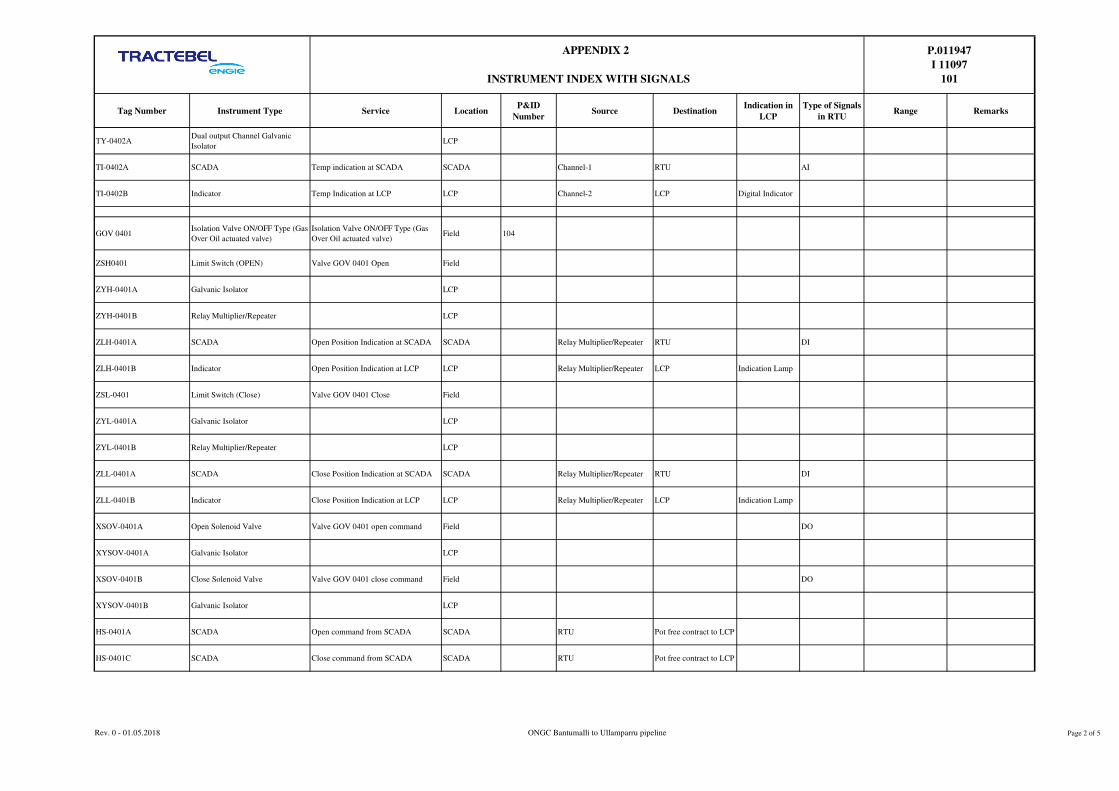
Tag Number Instrument Type Service LocationP&ID
NumberSource Destination
Indication in
LCP
Type of Signals
in RTURange Remarks
APPENDIX 2
INSTRUMENT INDEX WITH SIGNALS
P.011947
I 11097
101
TY-0402ADual output Channel Galvanic
IsolatorLCP
TI-0402A SCADA Temp indication at SCADA SCADA Channel-1 RTU AI
TI-0402B Indicator Temp Indication at LCP LCP Channel-2 LCP Digital Indicator
GOV 0401Isolation Valve ON/OFF Type (Gas
Over Oil actuated valve)
Isolation Valve ON/OFF Type (Gas
Over Oil actuated valve)Field 104
ZSH0401 Limit Switch (OPEN) Valve GOV 0401 Open Field
ZYH-0401A Galvanic Isolator LCP
ZYH-0401B Relay Multiplier/Repeater LCP
ZLH-0401A SCADA Open Position Indication at SCADA SCADA Relay Multiplier/Repeater RTU DI
ZLH-0401B Indicator Open Position Indication at LCP LCP Relay Multiplier/Repeater LCP Indication Lamp
ZSL-0401 Limit Switch (Close) Valve GOV 0401 Close Field
ZYL-0401A Galvanic Isolator LCP
ZYL-0401B Relay Multiplier/Repeater LCP
ZLL-0401A SCADA Close Position Indication at SCADA SCADA Relay Multiplier/Repeater RTU DI
ZLL-0401B Indicator Close Position Indication at LCP LCP Relay Multiplier/Repeater LCP Indication Lamp
XSOV-0401A Open Solenoid Valve Valve GOV 0401 open command Field DO
XYSOV-0401A Galvanic Isolator LCP
XSOV-0401B Close Solenoid Valve Valve GOV 0401 close command Field DO
XYSOV-0401B Galvanic Isolator LCP
HS-0401A SCADA Open command from SCADA SCADA RTU Pot free contract to LCP
HS-0401C SCADA Close command from SCADA SCADA RTU Pot free contract to LCP
Rev. 0 - 01.05.2018 ONGC Bantumalli to Ullamparru pipeline Page 2 of 5

Tag Number Instrument Type Service LocationP&ID
NumberSource Destination
Indication in
LCP
Type of Signals
in RTURange Remarks
APPENDIX 2
INSTRUMENT INDEX WITH SIGNALS
P.011947
I 11097
101
HS-0401B Push button open Open command from LCP LCP LCP XSOV 0401APress to release
PB
HS-0401D Push button close Close command from LCP LCP LCP XSOV 0401BPress to release
PB
HS-0401F Local/Remote Selection switch Local/Remote selection Field
HY-0401A Galvanic Isolator LCP
HY-0401B Relay Multiplier/Repeater LCP
XI-0401G SCADA L/R indication at SCADA SCADA Relay Multiplier/Repeater RTU DI
XI-0401F Indicator L/R indication at LCP LCP Relay Multiplier/Repeater LCP Indication Lamp
DPSH -0401 Differential Pressure SwitchDifferential pressure across valve
GOV 0401Field
DPSY 0401A Galvanic Isolator LCP
DPSY 0401B Relay Multiplier/Repeater LCP
DPAH 0401 A SCADA DPAH indication at SCADA SCADA Relay Multiplier/Repeater RTU DI
DPAH 0401 B Indicator DPAH indication at LCP LCP Relay Multiplier/Repeater LCP Indication Lamp
HS 0401E P/S/M selector switch P/S/M selection LCP
XI-0401G SCADA Panel mode selection at SCADA SCADA XI-0401G RTU DI
XI-0401F SCADAMaintainence Mode selection at
SCADASCADA XI-0401F RTU DI
XI-0401E SCADA SCADA Mode selection at SCADA SCADA XI-0401E RTU DI
PG-0403 Pressure Gauge Pig Launcher Y-0401 pressure Field 104 0-1 Barg with Gauge saver
PG-0404 Pressure Gauge Pig Launcher Y-0401 pressure Field 104 0-100 Barg
PG-0407 Pressure Gauge Pig Launcher Y-0401 pressure Field 104 0-100 Barg
Rev. 0 - 01.05.2018 ONGC Bantumalli to Ullamparru pipeline Page 3 of 5

Tag Number Instrument Type Service LocationP&ID
NumberSource Destination
Indication in
LCP
Type of Signals
in RTURange Remarks
APPENDIX 2
INSTRUMENT INDEX WITH SIGNALS
P.011947
I 11097
101
PG-0406 Pressure Gauge Upstream pressure HOV 0401 Field 104 0-100 Barg
PG-0405 Pressure Gauge 0403-NG-4"-6C1-N Field 104 0-100 Barg
TE-0403 Temp Element RTD 104 -20 to 100 deg C Surface Mounted
TT-0403 Temp Transmitter Ventline-0401-BD-4"-1C1-N Field 104
TY-0403A Dual Channel Galvanic Isolator LCP
TI-0403A SCADA Temp indication at SCADA SCADA Channel-1 RTU AI
TI-0403B Indicator Temp Indication at LCP LCP Channel-2 LCP Digital Indicator
XXS 0401 Pig indicator Minor Barrel-Y-0401 Field 104 Non Intrusive type
XXSY-0401A Galvanic Isolator LCP
XXSY-0401B Relay Multiplier/Repeater LCP
XXS-0401A SCADA Pig Indication at SCADA SCADA Relay Multiplier/Repeater RTU DI
XXS-0401 B Indicator Pig Indication at LCP LCP Relay Multiplier/Repeater LCP Indication Lamp
.
XXS 0402 Pig indicator Downstream of Barred Tee Field 104 Non Intrusive type
XXSY-0402A Galvanic Isolator LCP
XXSY-0402B Relay Multiplier/Repeater LCP
XXS-0402A SCADA Pig Indication at SCADA SCADA Relay Multiplier/Repeater RTU DI
XXS-0402 B Indicator Pig Indication at LCP LCP Relay Multiplier/Repeater LCP Indication Lamp
.
HOV-0401 Hydrulic Operated Valve ON/OFF valve outlet to Y-0401 Field 104
ZSH0401 Limit Switch (OPEN) Valve HOV 0401 Open Field
Rev. 0 - 01.05.2018 ONGC Bantumalli to Ullamparru pipeline Page 4 of 5

Tag Number Instrument Type Service LocationP&ID
NumberSource Destination
Indication in
LCP
Type of Signals
in RTURange Remarks
APPENDIX 2
INSTRUMENT INDEX WITH SIGNALS
P.011947
I 11097
101
ZYH-0401A Galvanic Isolator LCP
ZYH-0401B Relay Multiplier/Repeater LCP
ZLH-0401A SCADA Open Position Indication at SCADA SCADA Relay Multiplier/Repeater RTU DI
ZLH-0401B Indicator Open Position Indication at LCP LCP Relay Multiplier/Repeater LCP Indication Lamp
ZSL-0401 Limit Switch (Close) Valve HOV 0401 Close Field
ZYL-0401A Galvanic Isolator LCP
ZYL-0401B Relay Multiplier/Repeater LCP
ZLL-0401A SCADA Close Position Indication at SCADA SCADA Relay Multiplier/Repeater RTU DI
ZLL-0401B Indicator Close Position Indication at LCP LCP Relay Multiplier/Repeater LCP Indication Lamp
Corrosion Monitoring
ProbeCMS system 0402-NG-12"-6C1-N LCP 104 0-10 MPY
CM-A SCADA CM indication at SCADA SCADA Channel-1 RTU AI
CM-B Indicator CM Indication at LCP LCP Channel-2 LCP Digital Indicator
Rev. 0 - 01.05.2018 ONGC Bantumalli to Ullamparru pipeline Page 5 of 5
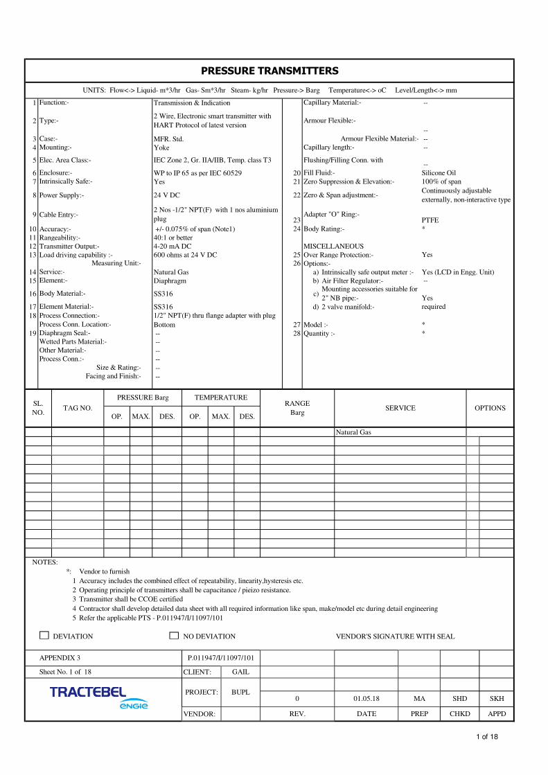
1 Transmission & Indication --
2
--
3 MFR. Std. --
4 Yoke --
5 --
6 WP to IP 65 as per IEC 60529 20 Silicone Oil
7 Yes 21 100% of span
8 Power Supply:- 24 V DC 22
9 Cable Entry:-23 PTFE
10 Accuracy:- +/- 0.075% of span (Note1) 24 *
11 Rangeability:- 40:1 or better
12 Transmitter Output:- 4-20 mA DC MISCELLANEOUS
13 Load driving capability :- 600 ohms at 24 V DC 25 Over Range Protection:- Yes
26 Options:-
14 Natural Gas a) Intrinsically safe output meter :- Yes (LCD in Engg. Unit)
15 Diaphragm b) Air Filter Regulator:- --
16 SS316 c)Yes
17 SS316 d) 2 valve manifold:- required
18
Bottom 27 Model :- *
19 -- 28 Quantity :- *
--
--
--
--
--
Natural Gas
NOTES:
*: Vendor to furnish
1 Accuracy includes the combined effect of repeatability, linearity,hysteresis etc.
2 Operating principle of transmitters shall be capacitance / pieizo resistance.
3 Transmitter shall be CCOE certified
4 Contractor shall develop detailed data sheet with all required information like span, make/model etc during detail engineering
5 Refer the applicable PTS - P.011947/I/11097/101
DEVIATION NO DEVIATION VENDOR'S SIGNATURE WITH SEAL
CLIENT:
VENDOR: REV.
SHD SKH
DATE PREP CHKD APPD
01.05.18 MAPROJECT:
0BUPL
Sheet No. 1 of 18 GAIL
APPENDIX 3 P.011947/I/11097/101
OPTIONS
OP. MAX. DES. OP. MAX. DES.
SERVICERANGE
Barg
Process Conn.:-
Size & Rating:-
Facing and Finish:-
SL.
NO.TAG NO.
PRESSURE Barg TEMPERATURE
Diaphragm Seal:-
Wetted Parts Material:-
Other Material:-
Element Material:-
Process Connection:- 1/2" NPT(F) thru flange adapter with plug
Process Conn. Location:-
Measuring Unit:-
Service:-
Element:-
Body Material:-
Zero & Span adjustment:-Continuously adjustable
externally, non-interactive type
Adapter "O" Ring:-
Body Rating:-
Mounting accessories suitable for
2" NB pipe:-
2 Nos -1/2" NPT(F) with 1 nos aluminium
plug
Enclosure:- Fill Fluid:-
Intrinsically Safe:- Zero Suppression & Elevation:-
Mounting:- Capillary length:-
Elec. Area Class:- IEC Zone 2, Gr. IIA/IIB, Temp. class T3 Flushing/Filling Conn. with
Type:-2 Wire, Electronic smart transmitter with
HART Protocol of latest versionArmour Flexible:-
Case:- Armour Flexible Material:-
PRESSURE TRANSMITTERS
UNITS: Flow<-> Liquid- m*3/hr Gas- Sm*3/hr Steam- kg/hr Pressure-> Barg Temperature<-> oC Level/Length<-> mm
Function:- Capillary Material:-
1 of 18

1 * 14 1/2" NPT(F)
2 4 Wire RTD 15 Two
3 Duplex 16 WP to IP 65 as per IEC 60529 / IS 2147
4 As per IEC 60751
5 Pt100 17 SS316
6 100 Ohm 18
7 Hermatically Sealed 19 Welded
8 20 1/2" NPT(F)
10 mm 21 TEIND-STD-G-J-4002
SS316 22
9 SS316
10 Four Wires a) 150 mm
11 Mineral(MGO)Insulated b) ________________
12 c) ________________
13 Accuracy Class A 23 Quantity :-
NOTES: 1 Element length shall be suitable for thermowell.
2
3 Vendor shall submit wake frequency and other test related test certificates,T/W drawings etc for approval during detailed engineering stage
4 RTD to be provided with 2 nos cable entries with one no. cable entry provided with suitable plug
5 Thermowell shall be of 900# rating
6 Refer the applicable PTS - P.011947/I/11097/101
* VENDOR TO FURNISH
DEVIATION NO DEVIATION VENDOR'S SIGNATURE WITH SEAL
MA SHD0 01.05.2018PROJECT: BUPL
SK
VENDOR: REV. DATE PREP
P.011947/I/11097/101
CHKD APPD
Sheet No. 2 of 18 CLIENT: GAIL
APPENDIX 3
Thermowell's immersion length shall be selected in such a way that tip of the thermowell shall preferably be at the centre of pipe to sense temperature properly.
FLANGELINE NO. / VESSEL
NO. / PIPING CLASSOPTION
NOR. MAX. DES. U T MATERIALRATING, FACING,
FINISH
SL. NO. TAG NO.
TEMP.°C WELL DIM.
No. of Wires:- Extra Nipple Extens
Insulation
Head Cover Type:- Screw Cap of Die Cast Aluminium with SS Chain
Matl.:- Options:-
Nipple & Union Matl.:-
Sheath: Inst. Conn.:-
O.D.:- Thermowell Dwg:-
Resistance at 0°C:- Construction:-Drilled bar stock upto immersion length 500 mm,
otherwise fabricated
Leads:- Process Conn:-
Calibration:- Thermowell:
Element Material:- Material:-
Element: No. of Entries:-
No. of Elements:- Enclosure Type:-
RESISTANCE TEMPERATURE DETECTORS ALONG WITH THERMOWELL
UNITS: Flow<-> Liquid- m*3/hr Gas- Sm*3/hr Steam- kg/hr Pressure-> Barg Temperature<-> oC Level/Length<-> mm
Assembly as per Drawing:- Cable Entry:-
2 of 18

1 * 14 1/2" NPT
2 4 Wire RTD 15 Two
3 Duplex 16 WP to IP 65 as per IEC 60529 / IS 2147
4 As per IEC 60751
5 Pt100 17 SS304
6 100 Ohm 18
7 Hermatically Sealed 19 Welded pad
8 20 1/2" NPT(M)
10 mm 21
SS316 a) Extra Nipple Extens as per site condition
9 SS316 b) Clamp
10 Four Wires c) ________________
11 Mineral(MGO)Insulated
12 22 Quantity :- -
13 Accuracy Class A
NOTES:
1 Vendor to element length as per site condition.
2 Vendor shall supply & select CLAMP thickness and size also related accessories which is suitable for available pipeline size
3 Contractor shall refer dwg no. TEIND-STD-G-J-4007 enclosed with tender. Element shall be direct surface contact type
4 Element lenth to suit the pad dimensions
5 RTD shall be provided with two cable entries with one cable entry provided with suitable plug
6
7 Refer the applicable PTS - P.011947/I/11097/101
* VENDOR TO FURNISH
DEVIATION NO DEVIATION VENDOR'S SIGNATURE WITH SEAL
RESISTANCE TEMPERATURE DETECTORS SKIN TYPE
UNITS: Flow<-> Liquid- m*3/hr Gas- Sm*3/hr Steam- kg/hr Pressure-> Barg Temperature<-> oC Level/Length<-> mm
Assembly as per Drawing:- Cable Entry:-
Element: No. of Entries:-
No. of Elements:- Enclosure Type:-
Calibration:- PAD:
Element Material:- Material:-
O.D.:-
Matl.:-
Nipple & Union Matl.:-
Resistance at 0°C:- Construction:- PAD
Leads:- Process Conn:-
Sheath: Inst. Conn.:-
RATING, FACING,
FINISH
No. of Wires:-
Insulation
Head Cover Type:- Screw Cap of Die Cast Aluminium with SS Chain
SL. NO. TAG NO.
TEMP.°C WELL DIM. FLANGELINE NO. / VESSEL
NO. / PIPING CLASSOPTION
NOR. MAX. DES. U T MATERIAL
APPENDIX 3
Contractor shall develop detailed data sheet with all the required information like element length, pad dimension, make,
model etc. during detail engineering
P.011947/I/11097/101
Sheet No. 3 of 18 CLIENT: GAIL
PROJECT: BUPL0
VENDOR: REV. DATE PREP CHKD
Options:-
APPD
01.05.2018 MA SHD SK
3 of 18

1 Transmission & Indication
2 2 Wire, Electronic Smart with HART protocol of latest version
3 MFR. Std.
4 Yoke
5 WP to IP 65 as per IEC 60529 / IS 2147
6 Elec. Area Class:- IEC Zone 2, Gr. IIA/IIB, temp. class T3
7 Yes
8 24 V DC
9 Cable Entry:- 1/2" NPT(F)
10 Accuracy:- +/- 0.1% of FSD
11 Self Diagnostic Facility:- Yes
12 Cold Junction compensation :- --
13 Transmitter Output:- 4-20 mA DC, HART
14 Load Capability:- 600 ohms at 24V DC
15 Pt100
16 As per IEC 60751
17 Options:-
a) Mount. Acc. For 2" pipe:- Yes
b) Yes (In Engg. Unit)
18 Model :- *
19 *
NOTES:
* : Vendor to furnish
1 TT shall be remote mounted
2
3 TT shall be dual compartment type
4 TT shall be CCOE certified
5 Contractor shall develop detailed data sheet with all the required information like make/model etc. during detail engineering.
6 Refer the applicable PTS - P.011947/I/11097/101
DEVIATION NO DEVIATION VENDOR'S SIGNATURE WITH SEAL
APPDVENDOR: REV. DATE PREP CHKD
MA SHD SK
GAILSheet No. 4 of 18 CLIENT:
TEMP.
OPTION
NOR. MAX. DES.
APPENDIX 3 P.011947/I/11097/101
TEMPERATURE TRANSMITTERS
UNITS: Flow<-> Liquid- m*3/hr Gas- Sm*3/hr Steam- kg/hr Pressure-> Barg Temperature<-> oC Level/Length<-> mm
Function:-
Type:-
Case:-
Mounting:-
SL.
NO.TAG No.
PROJECT: BUPL
The input for TT shall be RTD Pt 100, 4 wire Class-A. Two cable entries shall be provided with 1/2" (NPT (F) for RTD and
1/2" NPT(F) for out put signals
0 01.05.2018
Enclosure:-
Intrinsically Safe:-
Power Supply:-
Sensor Element:-
Calibration:-
SERVICERANGE °C
Intrinsically safe output meter (LCD) :-
Quantity :-
4 of 18

1 Direct 15 Diaphargm Seal:- --
2 Local Type:- --
3 150 mm Wetted Parts Material:- --
White with black inscriptions Others Material:- --
4 SS316 Process Connection: Size & Rating --
5 Beyonet type SS316 Facing & Finish:- --
6 Shatterproof glass Capillary Material:- --
7 WP to IP 65 as per IEC 60529 / IS 2147 Armour - Flexible Material:- --
8 Bourdon Capillary Length:- --
9 SS316 Flushing/Filling connection with:- --
10 SS316 16 Over Range Protection:- 130% of FSD
11 +/-1% of FSD 17 Blow Out Protection:- Yes
12 Micropointer 18 Options :- a) Snubber
13 1/2" NPT(M) b) Syphon c) Gauge Saver
Connection Location:- Bottom d) Liquid Filled casing e) Vaccum Protection
14 SS316 f) Solid front g) Two valve manifold
19 Quantity :- *
Natural gas g required
c
f Required
* Venodr to furnish
1 Contractor shall develop details data sheet with all the required information like make/model etc, during detail engineering
2 Refer the applicable PTS - P.011947/I/11097/101
DEVIATION NO DEVIATION VENDOR'S SIGNATURES WITH SEAL
BUPL
P.011947/I/11097/101
DATE PREP APPD
PROJECT:
CHKD
0 01.05.2018
VENDOR: REV.
MA SHD SK
Sheet No. 5 of 18 CLIENT: GAIL
APPENDIX 3
Zero adjustment:-
Connection:-
PRESSURE TEMPERATURE
SERVICE OPTIONSOP. OP. MAX. DES.
Pressure Element:-
Element Material:-
MAX. DES.
Socket Material
Accuracy:-
Movement:-
SL. NO. TAG NO.RANGE
Kg/Cm²
PRESSURE GAUGE
UNITS: Flow<-> Liquid- m*3/hr Gas- Sm*3/hr Steam- kg/hr Pressure-> Barg Temperature<-> oC Level/Length<-> mm
Type:-
Mounting:-
Window Material:-
Enclosure:-
Dial Size:-
Colour:-
Case Material:-
Bezel Ring:-
Required for
low range
5 of 18

1 Tag No. Quantity * *
2 Application For Instrumentation IS cables
3 Area Classification Zone 2, Gr.IIA/IIB, T3
4 Enclosure WP to IP 65 as per IEC 60529 / IS 2147
5 Material of Construction Die cast aluminium (LM6 alloy)
6 Overall Dimension *
7 Cover Screwed
8 Painting Surface : Light blue & Inside : White
9
10 Left Side 6 nos. - 1/2" NPT(F)
11 Right Side 6 nos. - 1/2" NPT(F)
12 Top Side -
13 Bottom Side -
14 Other -
15 Type Double compression type, Nickel plated Brass & WP to IP 65 as per IEC 60529 / IS 2147
16 Size 1/2" NPT(M)
17
18
19
20 Entry 2 nos, 1 1/2" NPT, Bottom
21 Type Double compression type, Nickel plated Brass & WP to IP 65 as per IEC 60529 / IS 2147
22 Size 1 1/2" NPT(M)
23
24
25 Type Spring loaded, antiloosening & vibration-proof, screwless clamp type
26 Quantity 48 Nos.
27 No. of Rows 2 Nos.
28 Numbering System Terminal strips & terminals shall be suitably numbered
29 Size 2.5 mm2
30 Make *
31
32 Telephone Socket & Plugs Not required
33 Plug 1/2" NPT(M) & 11/2" NPT(M)
34 Ground Busbar Required
35 Rail(s) for terminals Required
36 PVC hood alongwith Cable gland Required
37 Hinges Required
38 Nameplate Fixture Required
39 Gasket Neoprene Rubber
40 Hardware MS Zinc passivated
41 Mounting Suitable for mounting wall, column, steel structure
42 Manufacturer As per Approved /Recommended vender list
43 Model *
44
45
46
47
NOTES:
* : Vendor to furnish
1 Junction boxes shall have doors which shall be hinged type and these shall be fixed by plated countersunk screws.
2 Quantity of Cable glands & plugs shall be as per requirement.
3 Junction box numers based on cable schedule along with data sheet shall be submitted by contractor for approval
4 Refer the applicable PTS - P.011947/I/11097/101
DEVIATION NO DEVIATION VENDOR'S SIGNATURE WITH SEAL
APPDVENDOR: REV. DATE PREP CHKD
0 01.05.2018 MA SHD SK
Others
APPENDIX 3 P.011947/I/11097/101
GAIL
Multi CableCable Gland
Terminals
Options
PROJECT: BUPL
JUNCTION BOXES
General
Single
Cable
No. of Entry
Cable Gland
Sheet No. 6 of 18 CLIENT:
6 of 18
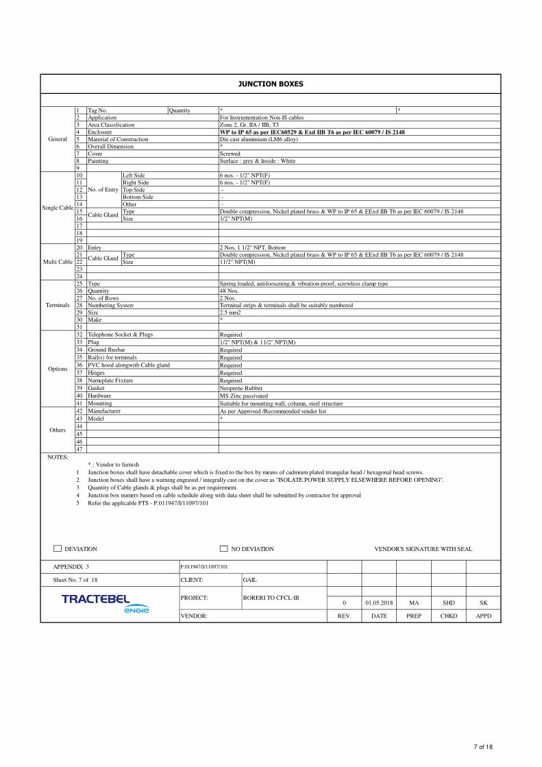
1 Tag No. Quantity * *
2 Application For Instrumentation Non-IS cables
3 Area Classification Zone 2, Gr. IIA / IIB, T3
4 Enclosure WP to IP 65 as per IEC60529 & Exd IIB T6 as per IEC 60079 / IS 2148
5 Material of Construction Die cast aluminium (LM6 alloy)
6 Overall Dimension *
7 Cover Screwed
8 Painting Surface : grey & Inside : White
9
10 Left Side 6 nos. - 1/2" NPT(F)
11 Right Side 6 nos. - 1/2" NPT(F)
12 Top Side -
13 Bottom Side -
14 Other -
15 Type Double compression, Nickel plated brass & WP to IP 65 & EExd IIB T6 as per IEC 60079 / IS 2148
16 Size 1/2" NPT(M)
17
18
19
20 Entry 2 Nos, 1 1/2" NPT, Bottom
21 Type Double compression, Nickel plated brass & WP to IP 65 & EExd IIB T6 as per IEC 60079 / IS 2148
22 Size 11/2" NPT(M)
23
24
25 Type Spring loaded, antiloosening & vibration-proof, screwless clamp type
26 Quantity 48 Nos.
27 No. of Rows 2 Nos.
28 Numbering System Terminal strips & terminals shall be suitably numbered
29 Size 2.5 mm2
30 Make *
31
32 Telephone Socket & Plugs Required
33 Plug 1/2" NPT(M) & 11/2" NPT(M)
34 Ground Busbar Required
35 Rail(s) for terminals Required
36 PVC hood alongwith Cable gland Required
37 Hinges Required
38 Nameplate Fixture Required
39 Gasket Neoprene Rubber
40 Hardware MS Zinc passivated
41 Mounting Suitable for mounting wall, column, steel structure
42 Manufacturer As per Approved /Recommended vender list
43 Model *
44
45
46
47
NOTES:
* : Vendor to furnish
1 Junction boxes shall have detachable cover which is fixed to the box by means of cadmium plated triangular head / hexagonal head screws.
2
3 Quantity of Cable glands & plugs shall be as per requirement.
4 Junction box numers based on cable schedule along with data sheet shall be submitted by contractor for approval
5 Refer the applicable PTS - P.011947/I/11097/101
DEVIATION NO DEVIATION VENDOR'S SIGNATURE WITH SEAL
Others
Junction boxes shall have a warning engraved / integrally cast on the cover as "ISOLATE POWER SUPPLY ELSEWHERE BEFORE OPENING".
APPENDIX 3
Multi CableCable Gland
Terminals
Options
P.011947/I/11097/101
JUNCTION BOXES
General
Single Cable
No. of Entry
Cable Gland
Sheet No. 7 of 18 CLIENT: GAIL
0 01.05.2018 MA SHDPROJECT: BORERI TO CFCL-III
SK
PREP CHKD APPDVENDOR: REV. DATE
7 of 18

1 To generate digital signal 21 a Set-point adjustable over span range
2 Diaphragm actuated b
3 22
4 23a)
5 IEC Zone 2, Gr. IIA/IIB, Temp. class T3 b)
6 WP to IP 65 as per IEC 60529 c)
7 Ex"d" d)
9 Set Point adjusment
10 Accuracy:- +/- 1%
11 Accuracy of setting indication:- +/- 1.5%
12 Switch Configuration:- Two SPDT
13 Switch Type:- Snap acting, shock and vibration proof
14 Switch Rating:- 24 V DC
14 Natural Gas
15 1/2" NPT(M)
16 Bottom 24 Model :- *
17 Viton, Buna-N 25 Quantity :- *
18 150% of maximum pressure
19 Suitable for full ring lugs for cable connection
20 two numbers, 1/2" NPT(F) with SS plug
Natural Gas
NOTES:
*: Vendor to furnish
Note:-
1 Process Data shall be as per Specification
2
3 Refer the applicable PTS - P.011947/I/11097/101
4 Vendor shall select the suitable model for each Tag no. such that the switch differential shall be with in the following limits.
5 Differential pressure Switch shall be mounted on Valve Actuator.
6 Calibration Report
DEVIATION NO DEVIATION VENDOR'S SIGNATURE WITH SEAL
Notes:
5.) Differential pressure Switch shall be mounted on Valve Actuator.
6) Calibration Report
LM-6 Cast Aluminum
DIFFERENTIAL PRESSURE SWITCH
UNITS: Flow<-> Liquid- m*3/hr Gas- Sm*3/hr Steam- kg/hr Pressure-> kg/cm*2 G Temperature<-> oC Level/Length<-> mm
Function:- Adjustibility:-
Type:-Differential adjustable by 10% of
span(minimum)
Nameplate:- Tag number, service engraved in stainless Case Material:-
Sensing Element Material:- SS-316L Accessories / Options:-1/2" NPT 5 valve SS-316 manifold
constructed from barstock
Elec. Area Class:-
Service:-
Process Connection:-
Process Conn. Location:-
Enclosure:-
Protection
Internal
Sealing Ring:-
Over Range:-
Terminal Block:-
Cable Entry:-
SL.
NO.TAG NO.
PRESSURE kg/cm2 TEMPERATURE ºc RANGE
SERVICE OPTIONS
OP. MAX. DES. MIN MAX. DES. SPAN SET
At the time of approval of DS, Supplier shall furnish DS along with Catalogues.
APPENDIX 3 P.011947/I/11097/101
The sum of the differential & repeatability (in Engg.Units)Shall be less than the difference between the set point and the normal operating pressure.
In other words, it shall be ensured that at no point of time the switch shall remain in Alarm status while the process is within the normal operating
range.
Sheet No. 8 of 18
GAIL
VENDOR: 0 01.05.2018 MA
PROJECT: BUPL
CLIENT:
SHD SK
REV. DATE PREP CHKD APPD

1 Panel Type
2 Panel Size (W X D X H)
3 MOC
4 Cable Entry
5 Colour
6 Internal Wiring
7 Protection Class
8 Indication on Panel
9 System capacity
10 Rest / Acknowledge
11 SIL 2 certification
12 Power Supply
13 Power Conversion
14 Meter range
15 Sensor Input
16 Alarm output
17 Digital Communication
18 Front Panel Option
19 Display
20 Operating Temp
21 Accuracy
22 Zero Drift
NOTE :
CLIENT: GAIL
PROJECT: BUPL
VENDOR: 0 01.05.2018 MA SHD SK
REV. DATE PREP CHKD APPD
Appendix 3
Sheet 9 of 18
Signal isolator / barriers, reapeters, multiplier shall be provided inside the panel.1
P.011947/I/11097/101
2 3 wire system is considered. Triad cables for interconnecting between gas detectors transmitter to gas detection system will be provided by
contractor. In case of contractor provides 2 wire transmittter, 3 core will be retained as spare.
Digital & Bar graph (LED lamp) indication for Power, inhibit, short circuit, open circuit,over range, fault &
Alarm. Reset / Accept Button. Zero & Span & alarm setting through Potentiometer.
Digital display in %LEL and 20 segment Bar graph display in % LEL.
0 deg C to + 50 Deg C
±3% of full scale over specified temperature range.
Less than 1% LEL per month.
Expandable to 1.5 times
Push Buttons for Reset and Acknowledge shall be illumination Push Button Switch
SIL 2 Certification as per IEC 61508
CO
NT
RO
LL
ER
24 VDC Solar Supply
Vendor to decide if any
0-100 % LEL/ 0 - 5 LEL Meter
Digital
Potential free contacts for alarm at 20% and 40% LEL per channel and sensor fault
Adjustable high, high high alarm (SPDT free potential relay contacts) and sensor fault alarm per channel and
interfce with RTU.
RS 485 Port for RTU/ SCADA Connectivity and one number spare
Datasheet-Addressable type Gas Detector Controller
Ga
s D
etec
tio
n P
an
el
Wall Mounting
600 X 400 X 600(Wall Mounted) (to be finalized during detail Engneering)
MS CRCA Thickness: 1.6 MM, Gland Plate: 3MM. The outer colour of the gas detection panel shall be as per
RAL 7035
Bottom
RAL 7035
0.5, 1.5 & 2.5 Sq MM Flexible Wires
IP 42 minimum
UPS/battery charger supply ON-OFF, 24VDC ON-Off , Rectifier/Diode Ring On-Off, Lamp Test , Battery On-
Off
3 Gas detection system contractor shall provide logic for reset of hooter and beacon and implement the same in gas detection system
4 Suitable terminal blocks shall be provided for terminating cables. Flying leads shall not be provided.
5 Gas detector controller cards shall be of OEM make
6 Refer the applicable PTS - P.011947/I/11097/101
7
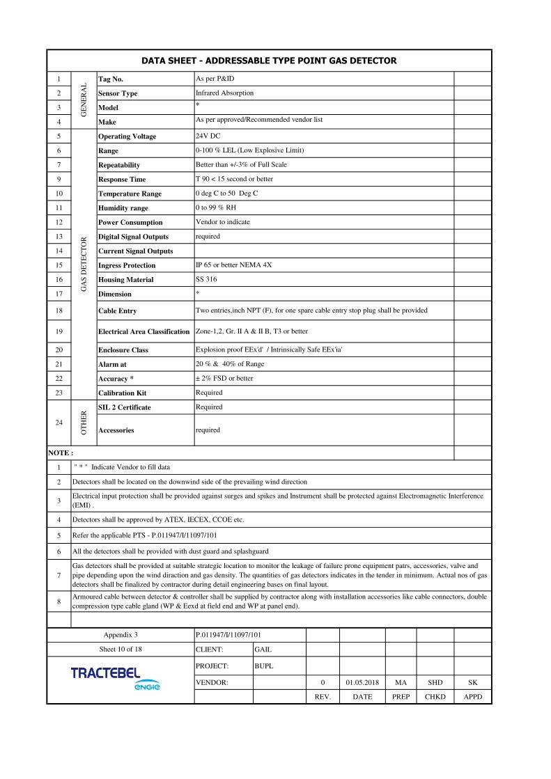
1 Tag No.
2 Sensor Type
3 Model
4 Make
5 Operating Voltage
6 Range
7 Repeatability
9 Response Time
10 Temperature Range
11 Humidity range
12 Power Consumption
13 Digital Signal Outputs
14 Current Signal Outputs
15 Ingress Protection
16 Housing Material
17 Dimension
18 Cable Entry
19 Electrical Area Classification
20 Enclosure Class
21 Alarm at
22 Accuracy *
23 Calibration Kit
SIL 2 Certificate
Accessories
1
2
3
4
5
6
7
8
CLIENT: GAIL
PROJECT: BUPL
VENDOR: 0 01.05.2018 MA SHD SK
REV. DATE PREP CHKD APPD
SS 316
*
Two entries,inch NPT (F), for one spare cable entry stop plug shall be provided
Zone-1,2, Gr. II A & II B, T3 or better
Armoured cable between detector & controller shall be supplied by contractor along with installation accessories like cable connectors, double
compression type cable gland (WP & Eexd at field end and WP at panel end).
Explosion proof EEx'd' / Intrinsically Safe EEx'ia'
All the detectors shall be provided with dust guard and splashguard
" * " Indicate Vendor to fill data
Detectors shall be located on the downwind side of the prevailing wind direction
Electrical input protection shall be provided against surges and spikes and Instrument shall be protected against Electromagnetic Interference
(EMI) .
Refer the applicable PTS - P.011947/I/11097/101
Gas detectors shall be provided at suitable strategic location to monitor the leakage of failure prone equipment patrs, accessories, valve and
pipe depending upon the wind diraction and gas density. The quantities of gas detectors indicates in the tender in minimum. Actual nos of gas
detectors shall be finalized by contractor during detail engineering bases on final layout.
Appendix 3
Sheet 10 of 18
P.011947/I/11097/101
20 % & 40% of Range
± 2% FSD or better
Required
required
NOTE :
OT
HE
R
24
Required
Detectors shall be approved by ATEX, IECEX, CCOE etc.
T 90 < 15 second or better
0 deg C to 50 Deg C
0 to 99 % RH
IP 65 or better NEMA 4X
Vendor to indicate
required
24V DC
DATA SHEET - ADDRESSABLE TYPE POINT GAS DETECTOR
GE
NE
RA
LAs per P&ID
Infrared Absorption
*
As per approved/Recommended vendor list
GA
S D
ET
EC
TO
R
0-100 % LEL (Low Explosive Limit)
Better than +/-3% of Full Scale

1
2
3
4
5
6
7
8
9
10
11
12
13
14
15
16
17
18
CLIENT: GAIL
PROJECT: BUPL
VENDOR: 0 01.05.2018 MA SHD SK
REV. DATE PREP CHKD APPD
P.011947/I/11097/101
3 Provision of alarm setting with buzzer sounder and visual indication shall be provided.
4 Accessories for mounting on panel shall be provided
5 Terminals shall be screwless clamp on type
Appendix 3
Multicolour back light LCD
*
Equipment Name
Type
Make
Model
Function
Mounting
DIGITAL PANEL INDICATOR
Microprocessor basaed , LED display, with engineering units (Dual channel)
Sheet 14 of 18
2 Indicator shall accept the 4-20 mA signals from pressure transmitter, temp transmitter, Level transmitter etc. Range
shall configurable according to instrument range.
Dimension
Panel cut out
Power supply
*
24V DC
Area Classification
1 Refer the applicable PTS - P.011947/I/11097/101
SAFE , control room munted
SAFE area
Required
As per Recommended vendor list
*
Indication , Engineering unit , Display
Flush mounted on Local control panel
5 digit, 7 segment back light display
Tag no.
Qty
Input Signal
NOTE :
+/- (0.1 %) of FS or betterMeasurement accuracy
Enclosure
Datasheet-Panel mounted Indicator
Alarm status
As per approved LCP BOM
4-20 mA(Refer Note 3)
Display
character type
Refer instrument index enclosed with tender.

1 Equipment Name
2 Type
3 Make
4 Model
5 Panel Type
6 Panel Size (W X D X H)
7 MOC
8 Cable Entry
9 Colour
10 Internal Wiring
11 Protection Class
12 Indication on Panel
13 Instrument/Electronic Earth
14 Electrical Earth
15 Accessories of Panel
16Three Poisition selector
switch
17 Operating Voltage
18 Non UPS input Voltage
19 Power consumption
20 Application
21 Area Classification
22 Earthing bolt
CLIENT: GAIL
PROJECT: BUPL
VENDOR: 0 01.05.2018 MA SHD SK
REV. DATE PREP CHKD APPD
P.011947/I/11097/101
4 Contractor shall develop finalize the requirements of barriers, relays, terminals and other LCP component as per PTS- Instrumentation and other
technical specfication attached with bid document.
5 Refer the applicable PTS - P.011947/I/11097/101
6 Contractor shall develop & implement the logic for SV station and other logic requirements as per P&ID in the LCP.
7
LOCAL CONTROL PANEL
CONVENTIONAL
As per vendor list
*
Indoor
Safe Area
IP 42 minimum
UPS/battery charger supply ON-OFF, 24VDC ON-Off , Rectifier/Diode Ring On-Off, Lamp Test . Selector
switch, process indicators, valve poisition indications etc.
Cabinet shall have single door from front and double door from back. Doors shall be provided with lockable handles (flush pull chrome plated
handles) and concealed hinges with pull pins for easy door removal. Panel Doors shall be provided with pockets for storing of manuals/ drawings
etc.
2
NOTE :
Required.
SCADA Mode/Panel Mode/Maintenance mode
Local control panel shall be provided with nicket palted brass cable glands of suitable size.3
1 Signal isolator / barriers, reapeters, multiplier , relay etc. shall be provided inside the panel.
Appendix 3
Sheet 13 of 18
Earth bus 25 x 6 mm copper
Earth bus 25 x 6 mm copper
Door Switch, Cable Glands, MCBS,Panel Light,Cooling Fan, 15 A Power socket, filter kit, anti vibration pad.
24 V DC
NA
*
Datasheet-Local Control Panel
Floor Mounted
1000 X 800 X 2100 (to be finalized during detail Engneering)
MS CRCA Thickness: 1.6 MM, Gland Plate: 3MM. Door thickness: 2mm
Bottom
RAL 7035-Exterior and Interior and Black for base frame
Gen
era
lL
oca
l C
on
tro
l P
an
el
Required
0.5, 1.5 & 2.5 Sq MM Flexible Wires

1 Equipment Name
2 Type
3 Make
4 Model
5 Mfg.Std.
6 Principle of Detection
7Maximum current stand by -
mA
8 Operating Voltage
9Max Permissible Alarm
Current - mA
10 Body
11 Mounting
12 Dimension
13 Colors
14 Weight
15 Application
16 Indication
17 Humidity Range
18 Temp. Range
19 Detector wire size
Approval 20 Product Certification
NOTE :
1
2
3
4
5
6
7
CLIENT: GAIL
PROJECT: BUPL
VENDOR: 0 01.05.2018 MA SHD SK
REV DATE PREP CHKD APPD
Refer the applicable PTS - P.011947/I/11097/101
Remote response indicator for detectors installed above flase ceiling and in the cable trenches shall be considered along with
detectors
Mounting accessories and tag plate shall be provided for detectors.
DATA SHEET-
MULTI SENSOR OPTICAL-PHOTO ELECTRIC SMOKE / THERMAL DETECTOR
Genral
Multi Sensor Photo Electric Smoke/Thermal Detector
Conventional
As per approved/Recommended vendor list
*
EN 54 Part 5(2000)
Function
Light Scattering & Thermistor
*
24 VDC
*
MOC
*
Surface
*
*
*
Service Condition
Indoor
Alarm condition : RED LED
Healthy condition : GREEN LED
5% to 95% Rh(Non condensing)
0 to +50 ° C
*
Appendix 3
LPCB/Vds/CE
Sheet 15 of 18
* - Vendor to Furnish
Bidder shall provide necessary Test / Calibration certificate
Bidder shall give more details as on above for better clarity of detector.
Bidder shall submit product catlogue with technical datasheet for reference , review and approval.
P.011947/I/11097/101

1 Model
2 Make
3 Type
4 Ingress Protection
5Material of
Construction
6 Finish
7 Terminals
8 Cable Entry
9 Supply Voltage
10 Humidity
11 Temperature
1
2
3
4
5
6
7
CLIENT: GAIL
PROJECT: BUPL
VENDOR: 0 01.05.2018 MA SHD SK
REV. DATE PREP CHKD APPD
24 V DC or 48 VDC
0 - 95 % R.H.
0 - 65 degc
Beacon shall be of stroboscopic type
" * " Indicate Vendor to fill data
2 nos. 3/16" Stud type terminals
Two. Entries, spare entry to be plugged with suitable plug
DATA SHEET - BEACON
BE
AC
ON
Flashing colour shall be orange
*
*
Rotating & Flashing Light
IP 65
CAST Aluminium Alloy LM6
Inside & Outside light grey Epoxy Powder coating
Common beacon shall be provided for gas detection system and fire detection system. Contractor shall provide
necessary provision to integrate alarm signals from two different systems. Also contractor shall make
necessary provision for two different visual alarms for gas detection system alarm and fire detection system
alarm with same beacon.
Refer the applicable PTS - P.011947/I/11097/101
Appendix 3
Sheet 12 of 18
NOTE :
P.011947/I/11097/101
Beacon for hazardous area shall be explosion proof to Eexd, IIA/IIB, T3
Beacon flashing frequency shall be 1 flash/sec

1 Model
2 Make
5 Ingress Protection
6 Material of Construction
7 Flameproof Group
9 Finish
10 Terminals
11 Sound Level
12 Supply Voltage
13 Cable Entry
14Field Mounted Reset Push
Button
15 Humidity
16 Temperature
1
2
3
4
5
6
CLIENT: GAIL
PROJECT: BUPL
VENDOR: 0 01.05.2018 MA SHD SK
REV. DATE PREP CHKD APPD
Refer the applicable PTS - P.011947/I/11097/101
Two entries, NPT (F), for one spare cable entry stop plug shall be provided.
Required
*
As per approved/Recommended vendor list
Flameproof , E'exd and WP to IP65 or better
CAST Aluminium Alloy LM 6
Zone - 1 & 2, Gas Group IIC, TEMP. Class - T3
Inside & Outside light grey Epoxy Powder coating
0 - 95 % R.H.
0 - 65 degc
DATA SHEET - HOOTER
HO
OT
ER
90 to 110 db @ 3 Mtr.
24 V DC or 48 VDC
CLIP - ON Type Terminals
NOTE :
Appendix 3
Sheet 11 of 18
P.011947/I/11097/101
Hooter for safe area shall be weather proof to IP 65 or better
Common hooter shall be provided for gas detection system and fire detection system. Contractor shall provide necessary
provision to integrate alarm signals from two different system. Also contractor shall make two necessary provision for two
different alarm tones for gas detection system alarm and fire detection system alarm with the same hooter
" * " Indicate Vendor to fill data
Hooter for LEL High & High highAlarms shall be provided in Station Control Room Gas Detection Cabinet / Panel and also in
outdoor.
Hooter shall be CCOE/ PESO certified for explosion proof (flame proof) .

1 Equipment Name
2 Type
3 Make
4 Model
5 Mfg.Std.
6 Principle of MCP
7 Operating Voltage
8 Current Consumption - A
9 Body
10 Mounting
11 Dimension
12 Colors
13 Weight
14 Application
15 Indication
16 Humidity Range
17 Temp. Range
18 MCP wire size
Approval 19 Product Certification
Note
1
2
3
4
5
6
7
8
CLIENT: GAIL
PROJECT: BUPL
VENDOR: 0 01.05.2018 MA SHD SK
REV DATE PREP CHKD APPD
Manual call point for hazardous area shall be CCOE certificate.
Refer the applicable PTS - P.011947/I/11097/101
Accessories like mounting accessories, tag plate, SS316 hammer & chain shall be supplied along with manual call point
Manual call point for hazardous area shall be explosion proof to Eexd IIA/IIB and weather proof to IP 65
MANUAL CALL POINT
Genral
Manual Call Point
Conventional (Break glass type)
As per approved/Recommended vendor list
*
EN 54 Part 11
Function
PRESS - Type Re-Settable
24 VDC
*
MOC
LM6 dia cast Aluminum
Surface
*
*
*
Service Condition
Indoor / Outdoor
Required, Alarm LED
0-to 95% Rh(Non condensing)
0 to +50 ° C
*
Appendix 3
Sheet 16 of 18
LPCB/Vds/CE
P.011947/I/11097/101
* - Vendor to Furnish
Bidder shall provide necessary Test / Calibration certificate
Bidder shall give more details as on above for better clarity of Manual call point during detail engineering.
Bidder shall submit product catalogue with technical datasheet for reference , review and approval.

:
:
:
:
:
:
:
:
:
:
:
:
:
:
:
:
:
:
:
:
:
:
:
:
:
:
:
:
:
:
:
:
:
CLIENT: GAIL
PROJECT: BUPL
VENDOR: 0 01.05.2018 MA SHD SK
REV DATE PREP CHKD APPD
PIG SIGNALLER MOUNTED ON PIPELINE
( NON-INTRUSIVE TYPE)
Type
At passage
Natural Gas – Non Sour
Pipeline mounted-downstream to 18”x18” flow tees /*
98
(-)20 to (+)65
DESIGN CONDITION :
GENERAL:
Manufacturer Name
1% Minimum
Sensing Element
Sensor Repeatability
Detection
Signal Output
Above ground
No
Non-Intrusive (Bi-directional)
Multiphase Product (Yes / No)
SENSING ELEMENT :
Sheet 17 of 18
Appendix 3 P.011947/I/11097/101
Power Supply
Signal Interface
Electrical Entry
PIG DETAILS :
Pig Length
Pig Diameter
Service
Location/pipeline detail.
Pressure in Bar(g)
Temperature in 0C
Installation
Magnetic type
Pig Velocity (Max. / Normal)
OTHERS :
95% ~ 100% of Pipeline ID
8 m/s
Particle & Pig Detection
Spectrum analysis using associated
software
½”NPTF (Four Nos. ½”NPTF cable gland entries are to be provided. One (1) nos. for signal, One (1)
nos. for power, One (1) for communication and one (1) nos. as a spare. All entries shall be supplied
with suitably Ex’d’ entry plugs.)
Carbon Steel/ Poly urethane
600mm ~ 3000mm (indicative)
Tag Nos.
Design Standard
Electrical Area Classification
Pig Detection
Pig Material
**
*
ASME BPVC SEC VIII Div 1 (Latest edition), ASME B31.8 (Latest edition)
IEC zone-1 / zone-2, Gas Group IIA/IIB, Temp. Class T3
Non Intrusive
1 no. potential free contact (DPDT), 1 no serial communication interface (Modbus over RS-485 /
Ethernet)
Required and Pig Signaller shall be capable of detecting all type of pigging devices (permanent
magnet type and transmitter equipped intelligent pigs).
Required
AISI SS316L
24V,DC + 10%
Local control panel and RTU
ENCLOSURE :
Body Material
Degree of Protection EEx ‘d’, IP- 65
Seals
Cable gland
Red LED based, EExe/EEx’d’, IIB, T5, IP65 (visible/locate from min. 5 meters)
Black colour, EExe/EEx’d’, IP65 (visible/locate from min. 5 meters)
Up to 60 days of measurement data
Required with a minimum lifespan of 1 year) Required (All Pig Signaler shall have two (2) nos. of
inbuilt batteries (1 working + 1 spare), with a minimum lifespan of 1 year)
Required, AISI SS316L material. Termination box of EExe / EEx’d’ type shall be suitable for
hazardous area classification for connecting the sensor cables , power and signal cables, the light
indication and reset switch as applicable
ASTM A 320 L7 & ASTM A194 Gr.4/ Gr.7
Viton
Required and shall be EExe / EExd certified double compression type with PVC shrouds.
Local Indicator
Local Reset Button
Data Storage Capacity
Inbuilt Battery
Termination Junction Box
Bolting & Nut Material

1 Tag No. Quantity * *
2 Line No. Schedule * *
3 Vessel No. *
4 Safety / Relief Safety relief
5 Full Nozzle Full Lift/Mod. Nozzle Full nozzle full lift
6 Bonnet type Closed
7 Conv./Bellows/Pilot Operated Conventional
8 Inlet Conn. Size & Rating *
9 Facing & Finish *
10 Outlet Conn. Size & Rating *
11 Facing & Finish *
12 Cap Over Adj. Bolt Yes
13 Screwed / Bolted Bolted
14 Lifting Gear - Type
15 Test Gag Yes
16
17
18 Body and Bonnet A351 CF8M
19 Nozzle and Disc SS316
20 Spring SS304
21 Bellows --
22
23
24 Resilient Seat Seal --
25
26
27 Code API
28
29
30 Fluid State Natural Gas Gas
31 Corrosive Constituent
32 Required Flow Capacity
33 Mol.Wt. S.G. at Rel. Temp
34 Oper. Pressure Normal
35 Oper. Temp. Rel. Temp.
36 Valve Discharges to Atmosphere
37 Back Press. Const. Or Variable Variable
38 Set Pressure
39 Cold Bend Test Pressure
40 % Over Pressure % Blow Down 21%
41 Cp/Cv Compressibility Factor
42 Viscosity @ Rel. Temp. mPas(cP)
43 Vess. Wall Temp. Surf.Area-m2
44
45 Calculated Area cm2 *
46 Sel. Area cm2 Orifice Design * *
47 No. of Valves Reqd. for capacity *
48 Tota Area - cm2 *
49 Actual Flow Capacity *
50
51 Model No. *
52 IBR Certification No
53
54
NOTES:
'*' : Venodr to furnish
DEVIATION NO DEVIATION VENDOR'S SIGNATURE WITH SEAL
PRESSURE RELIEF VALVEUNITS: Flow<-> Liquid- m*3/hr Gas- Sm*3/hr Steam- kg/hr Pressure-> kg/cm*2 G Temperature<-> oC Level/Length<-> mm
General
Valve
Material
Options
Basis
Service
conditions
Orifice
APPENDIX 3 P.011947/I/11097/101
Sheet 18 of 18 CLIENT: GAIL
PROJECT: BUPL
0 01.05.2018 MK SHD SK
VENDOR: REV. DATE PREP CHKD APPD

PTS – REMOTE TERMINAL
UNIT
P.011947
I-11097
102
ONGC BANTUMILLI TO ULLAMPARU PIPELINE KG
BASIN
TRACTEBEL ENGINEERING PVT. LTD.
PTS – REMOTE TERMINAL UNIT
DOC. NO. P.011947 I 11097 102
0 01.05.2018 Issued for Procurement AS SK SKH
REV. DATE Subject of Revision Prepared By Checked By Approved By

PTS – REMOTE TERMINAL
UNIT
P.011947
I-11097
102
Rev. 0 ONGC - Bantumilli Ullamparu Pipeline Project Page 1 of 1
TABLE OF CONTENTS
1.0 INTRODUCTION ................................................................................................................. 1
2.0 REFERENCE ........................................................................................................................ 1
3.0 PROJECT BRIEF .................................................................................................................. 1
4.0 POWER SUPPLY .................................................................................................................. 1
5.0 ENVIRONMENTAL SPECIFICATIONS .................................................................................. 1
6.0 DESIGN CRITERIA ............................................................................................................. 1
7.0 REMOTE TERMINAL UNIT .................................................................................................. 2
8.0 DRAWINGS AND DOCUMENTATIONS ................................................................................ 7
9.0 INSTALLATION & COMMISSIONING.................................................................................. 9
10.0 EQUIPMENT INSPECTION & TESTING ............................................................................. 10
11.0 TRAINING ........................................................................................................................ 12

PTS – REMOTE TERMINAL
UNIT
P.011947
I-11097
102
Rev. 0 ONGC - Bantumilli Ullamparu Pipeline Project Page 1 of 13
1.0 INTRODUCTION
1.1 This specification covers the basic requirements of RTU along with associated equipment purchased as a
"Single point responsibility package unit" for this project.
2.0 REFERENCE
This document shall be read in conjunction with scope of work C&ID -Refer – SCOPE OF WORK C&I
Also refer Annexures enclosed with PTS-Remote terminal unit
Annexure - I- Input output list
Annexure – II – IO counts
3.0 PROJECT BRIEF
3.1 The entire project is comprised of dispatch station, receiving station and remote operated SV stations along
with associated instrumentation and protection system. Refer P&ID for detail.
3.2 BANTUMALLI DESPATCH STATION
a. New RTU as per specification and input output list.
b. Proposed RTU shall be of existing “SYNERGY” make.
3.3 ULLAMPARRU STATION
a. Existing RTU of Make- M/s SYNERGY - New RTU is not envisaged. All the new stations signals
shall be integrated in existing RTU. Additional 32 channel DI cards is required.
3.4 SV STATION
a. New RTU as per specification and input output list.
b. Proposed RTU shall be of existing “SYNERGY” make.
4.0 POWER SUPPLY
Electrical power supply 230 V AC, 24 V DC and 48 V DC UPS power supply will be given at one point
(AC/DC PDB) and from there vendor shall lay power cable upto to the require place. Further distribution
shall be in the scope of the vendor. If any other voltage levels are required, then all necessary conversions
shall be in the scope of vendor.
5.0 ENVIRONMENTAL SPECIFICATIONS
All equipment shall be designed for operation, storage and transportation under the following environmental
condition:
Max. / Min. Temperature 0 °C / 55 °C
Design temperature (-) 20 °C to 60 °C
Relative Humidity 95%
Hazardous Area Classification Zone 2, Gas Group II A or B, Temp. Class
T 3
Control Room & Electrical Room Safe Area
6.0 DESIGN CRITERIA
6.1 RTU shall have capability of updating process parameters data and configuration data in its own built-in
memory. Time stamping of all field values shall be required at RTU. In the event of failure or break of
communication link, the RTU shall continue to scan all parameters and update its database. RTU must
retain complete database analog & digital information of the field until it completely and correctly read by
SCADA Station to take care of no loss of data in case of failure of communication. The RTUs shall be

PTS – REMOTE TERMINAL
UNIT
P.011947
I-11097
102
Rev. 0 ONGC - Bantumilli Ullamparu Pipeline Project Page 2 of 13
designed to scan the field and store in the memory a minimum of 7000time stamped events (analog, digital,
diagnostics etc) during the period of communication outage for retrieval by MCS subsequently.
6.2 Vendor is required to incorporate the complete requirements of telemetered points for SCADA system
taking the inputs from the I/O point list. The RTUs I/O cards shall be considering the complete I/O
requirements of RTU I/O count.
6.3 Vendor shall furnish the poll time calculations during detail engineering considering the requirements of
50% I/Os parameter changes every poll. The calculation shall be carried out by properly and evenly
distributing the RTU over the communication channels.
The RTU shall comprise the following subsystems:
• Central processor with system software.
• Analogue input
• Contact (digital) input
• Contact (digital) output
• Modbus Serial ports configurable (RS 232/485)
• Ethernet port(Redundant)
• Diagnostic port
• USB Port/SD card
6.4 RTU software
• Programming software as per IEC 61131
• Cyber security as per IEC 62443/ISO 27001
• Local and remote Diagnostic tool
6.5 Any additional interfacing device if required to achieve the functionality as per the philosophy mentioned
elsewhere in this document shall be provided or consider during bid stage.
7.0 REMOTE TERMINAL UNIT
7.1 RTU shall have dual Ethernet ports (configurable independently) for TCP/IP communication with SCADA
system on multi-dropped environment. Both the communication port should support Class 0, 1, 2 & 3
polling from SCADA independently.
7.2 RTU should compatible with Centralized SCADA system. The RTU should support DNP 3.0 protocols
for communication with SCADA Servers and MODBUS (RTU) for communication with IEDs.
7.3 The ports for communication with Servers shall be available on a separate card than the card being used for
interfacing with IEDs. Serial ports available at serial card should be independently and individually
configurable in all respect.
7.4 All interfacing cables from RTU to IEDs shall be armoured. All communication cables from RTU to
Telecom equipment shall be armoured
7.5 The RTUs shall be microprocessor based programmable units with both erasable ROM and RAM memory.
Each of the RTUs will have its own processor, memory, power supply unit & communication processors
and I/O cards complete in all respects. All RTUs will be modular and from the same model product line
with identical capabilities.
7.6 The complete RTUs will be supplied with all its components including the cabinets.
7.7 The I/O cards will not be combined for the functionalities i.e. each card will perform dedicated functionality
w.r.t analog input, analog output, digital input, digital output
7.8 All the supplied RTUs will be with same make & model no., differing only in number of RTU I/O cards.

PTS – REMOTE TERMINAL
UNIT
P.011947
I-11097
102
Rev. 0 ONGC - Bantumilli Ullamparu Pipeline Project Page 3 of 13
7.9 RTU should have surge/lightening protection for 24V input power supply and all Ethernet, Serial and
Communication ports. All field signals interfacing with RTU shall be surge protected.
7.10 The Digital Output shall be configured for pulse duration. No separate program or logic will be acceptable
at RTU end. On RTU restart/ power failure, RTU shall not reset the output circuit, shall not generate false
control signal and shall necessarily cancel all pending control signal.
7.11 AI, DI and DO card of the RTU shall be as per actual requirement (in addition to spares). The AO card (If
any) shall have minimum 4 I/O points. The serial card shall have minimum 4 ports.
7.12 RTU configurator software licenses shall be preferred in software (software key) form instead of hardware
(dongle). Multiuser software licenses shall be provided.
7.13 RTU shall have diagnostic provision without uploading /downloading RTU configuration to PC/laptop.
7.14 RTU configurator tool shall be compatible with 64-bit O.S i.e. Minimum Window 7 Basic & Enterprise and
above, Window Server 2008 R2 Standard & Enterprise edition and above. In case RTU software installation
in PC or server requires additional software like dot NET, java etc, it should be declared and provided by
RTU Vendor.
7.15 RTU configuration and diagnostic tool should be able to connect to RTU remotely over TCP/IP even during
polling from SCADA FEP on same TCP/IP.
7.16 RTU shall preferably have provision of authentication while connecting configuration and diagnostic tool
should use authentication like username and password.
7.17 RTU configuration and diagnostic tool should preferably have provision to warm restart of RTU.
7.18 RTU login shall be authorized using User Id and Login to do any configuration changes. RTU configurator /
diagnostic software shall have the following provision:
• Index of all I/O along with present real time field data to be available in diagnostic software
table/window.
• All RTU cards, serial ports and communications channels health points are to be configured in RTU
and DNP index of same are to be reflected in I/O list.
7.19 The RTUs will comprise the following subsystems:
• Central processor with system software
• Analogue input
• Contact (digital) input
• Analogue output
• Contact (digital) output
• Communications (Redundant)
• Serial ports
• Power supply (Redundant)
• Diagnostic (on-line from MCS and off-line diagnostics)
7.20 RTU Features
The RTU sub-system shall support the following:
a) Scanning of Input and Output
b) Discrete control with interlocks, supporting check before executes and control time out feature.
c) Derivation of calculated digital points based on logical arithmetic functions (AND, OR, NOT).
d) Derivation of calculated analog points based on arithmetic functions and driving external hardware.
e) Calculation shall be performed in RTU in engineering units with 16bit floating point accuracy.

PTS – REMOTE TERMINAL
UNIT
P.011947
I-11097
102
Rev. 0 ONGC - Bantumilli Ullamparu Pipeline Project Page 4 of 13
f) Interfacing with PLC systems/third party systems for data.
g) Separate database for separate polling sequences in multiple directions.
h) Integrated Web based HMI for remote supervision via web browser over SCADA network.
i) DNP 3.0 over TCP/IP protocol or IEC 60870-5-104 protocol for communicating with the SCADA
Master Control station. However, the following standard communication protocols shall also be
supported by the RTUs: - DNP 3.0 or IEC 60870-5-101, Modbus TCP/IP or Modbus RS485.
j) Full RTU diagnostics shall be available in the SCADA Engineering Workstations.
k) Automatic time synchronization of Remote telemetry units shall be implemented from MCS.
7.21 The RTUs shall have a self-diagnostic feature and software watchdog timer devices to monitor & report the
healthiness of CPU, memory, power supply, comm. interfaces and Input/ Output modules at the local level.
7.22 RTU shall be capable of updating process parameters data and configuration data in its own built-in
memory. Time stamping of all field values at RTU level. In the event of failure or break of communication
link between SCADA Master Control station and RTU, the RTU will continue to scan all parameters and
update its database.
7.23 For long term communication outage with Master control station; the RTUs shall be designed to scan the
field and store in the memory a minimum of 7000time stamped events (analog, digital, diagnostics etc)
during the period of communication outage for retrieval by MCS subsequently.
7.24 The RTU memory sizing shall be adequate to meet the above requirement. In case additional memory cards
are required to meet this requirement, same shall be provided by the vendor. RTUs buffer shall be circular
buffer with new events replacing old events.
7.25 RTU shall support communication protocol supporting report by exception to prevent unnecessary data
communication when the data is not changing.
7.26 It shall have feature of connecting a pluggable Programmable Diagnostic Test unit (PDT) with keyboard &
monitors diagnostic and programming aid to trouble shoot and configuration tool for RTU and I/O boards.
It shall be possible to exercise all the functions of the RTU without disconnecting the RTU from process.
7.27 Digital inputs
Typical specification of Digital Input channels is as given below:
Input Type : Volt free contacts (2 wire isolated)
Contact Wetting : 2-4mA per input at 24V DC
Resistance recognized : Not exceeding 1 Kilo Ohms as a closed contact
Resistance recognized : Not less than 50 Kilo Ohms as an open contact
Isolation : Using optocouplers or vendor specific.
Insulation resistance : 20M ohms at 500V DC inputs
Debounce circuitry : 10 m/sec
Indicators : Loop & state LEDs for each DI point
Voltage withstand : 1.5 KV RMS Capability
7.28 DIGITAL OUTPUTS
Typical specification of Digital Output channels is as given below:
Output Type : Relay contacts
Indicators : LED indication for each DO point
Relay Type : Miniature power relay

PTS – REMOTE TERMINAL
UNIT
P.011947
I-11097
102
Rev. 0 ONGC - Bantumilli Ullamparu Pipeline Project Page 5 of 13
Contact arrangement : 1 NO + 1 NC relay contacts configuration to be provided up to the
RTU terminal block
Contact Rating : Potential free contact rating of output interposing relay for each DO
point
(Contact rating 48 V DC, 2A; 230V AC, 5A)
(Vendor to provide interposing relays for each digital output point)
Isolation : 2KV RMS Contacts to Logic
DO command activation : Configurable Pulse duration
Security : Output contacts shall be monitored via opto-isolators, shall be short
circuit proof and protected by suitable mechanism like fuse with
suitable visual fuse blown indication provided.
7.29 Analog inputs
Typical specification of Analog Input channels is as given below:
Input Type : Isolated, Current Inputs
Ranges : 4 - 20 mA/1-5V
Multiplexer : Vendor standard
ADC Type : 12 bit binary (exclusive of sign bit)
Series Mode rejection : Greater than 30 db at 50 Hz
Common Mode rejection : Greater than 100 db at 50 Hz
Roll over error : 1 bit
Temperature : 0.005% per degree C
Coefficient
Accuracy : ± 0.1% of range including drop in resistor
7.30 The control device shall be configured such that failure of any part of an RTU subsystem (module) except
the CPU, power supply module shall not directly affect the integrity of the unit, as a whole.
7.31 COMMUNICATIONS
The RTU shall support both internal and external communications functions.
The communications network internal to the RTU shall be designed and implemented in such a way that the
passing of data and commands between modules shall not be prevented by the failure of any module not
directly involved in the communication exchange. In addition, the internal network shall not become
overloaded under the heaviest traffic possible in RTUs ultimate expansion configuration.
Each RTU shall recognize its own unique address. The LED indication shall be provided in the RTU to
check the health of RTU communication.
7.31.1 Automatic time synchronization of RTU shall be implemented from SCADA master control Station with a
resolution of 100 msec.
7.31.2 The RTUs shall have a self-diagnostic feature and software watchdog timer devices to monitor & report the
healthiness of CPU, memory, power supply, comm. interfaces and Input /Output channels at the local level.
Further, the RTUs shall support remote diagnostics from different station so that all these statuses shall be
transmitted to MCS and displayed in the RTU status graphic.
7.31.3 The analog input card shall generate an event, if it is out of calibration, which shall be sent to MCS. Further,
if analog output card is not self-calibrating type then all analog outputs shall be wired back as analog inputs
and calculations performed on each channel to detect AO card out of calibration. This out of calibration
shall be available as part of RTU status graphic along with set point value displayed in the graphic, next to
the corresponding controller symbol.
PTS – REMOTE TERMINAL
UNIT
P.011947
I-11097
102
Rev. 0 ONGC - Bantumilli Ullamparu Pipeline Project Page 6 of 13
7.31.4 RTUs shall be intelligent in support of the following:
a) It shall process the analog data for high-low limit violations as per stored limit tables and communicate
the same to MCS along with time stamping.
b) Linear conversion to engineering units and input filtering, in case engineering unit conversion is being
done at RTU level [conversion of raw data to normalized value (e.g. 0 to 1.0) for communication shall
also be acceptable].
c) To support remote reconfiguration and downloading of parameters i.e. addition, deletion, modification
and reassignment with different range, limits etc. from MCS to avoid local engineering at RTU level.
The following requirements of RTU configuration from MCS station shall be fulfilled:
• Analog alarm limits
• Analog scaling factor for engineering unit conversion
• Threshold value
• Smoothing factor (filter time constant) etc.
7.31.5 In case of failure of complete RTU or off-scan of complete RTU, only one alarm shall be generated and the
RTU analog & digital points shown in various graphics and printed in reports shall correspondingly have
data integrity qualifier flag.
7.31.6 The I/O point wires shall not be directly terminated on the RTU I/O boards. Screw less Terminal blocks/
shall be provided in the RTU cabinet. I/O termination blocks shall have both male and female portions so
that to isolate the field wiring at RTU level, male/ female termination block attached to the field wiring can
be pulled out instead of removing the wiring. Cross ferruling shall be done.
7.31.7 The electronics in the RTU shall consist of plug-in PCB's or units with Gold plated edge connectors that
utilize a wiping action for connection for PCB's to the back frame wiring. Vendor shall detail the shelf and
inter-shelf wiring and the termination of the wiring harness between the RTU and the terminal block area.
Easy access to cabinet wiring, for maintenance purposes is essential. The PCBs and RTU components shall
be designed for high temp rating and low power consumption so that air exchange with the ambient
environment will not be required.
7.31.8 The RTU shall be immune to radio frequency interference generated by any nearby source meeting the
latest international standards in this regard (MIL, VDE etc.).
7.31.9 The RTU equipment shall function continuously without requiring any preventive maintenance.
7.31.10 Vendor to ensure that the open/ close status of valves (open state first wired and thereafter close state) be
wired consecutively in the RTUs.
7.31.11 Identification labels for RTUs, RTU card files, power distribution boards, terminations etc complete in all
respects properly correlating with the drawings is to be ensured by the SCADA Vendor.
7.32 SCAN Rates
The local scan rates for individual I/O channels shall be such that the time-tagging resolution and system
performance requirements are achieved.
The consideration of scan times shall include the acquisition of data, processing and updating of the RTU
database. The overall local scan shall be defined as the time required to acquire field data and update the
RTU database and the same shall be much faster than RTU poll time by SCADA station. It is expected that
scan rate shall not exceed 100 msec.
7.33 SET-Point Controls
a) All analog output control functions shall utilize the select-check-operate control sequence associated
with set point control.
b) At the RTU, failure of a module in a subsystem shall be identified by an individual LED display.
c) Each I/O protected against the reversal polarity of the power voltage to I/O.

PTS – REMOTE TERMINAL
UNIT
P.011947
I-11097
102
Rev. 0 ONGC - Bantumilli Ullamparu Pipeline Project Page 7 of 13
7.34 Serial Link Requirement
a) Vender shall provide appropriate number of RS 485 & RS 232 serial ports for each RTU as per tender
requirement.
b) Vendor shall provide all the software tools and programs (source code) used to interface RTUs with
different IEDs. CLIENT shall integrate other IEDs with the RTU in future. Hence, RTUs shall have all
necessary software, compilers, tools that makes device compatible with third-party IED device.
Integration of IEDs (of any protocol and not just MODBUS) with the RTUs shall be totally end-user
configurable.
c) The alarms for power supply/ serial link failure/ malfunction through serial link.
d) The RTU memory sizing shall be adequate for required nos. (As applicable) of IED system & serially
connected with the RTU including the spare ports.
e) All RTUs shall be user programmable for interfacing with any kind of IEDs like Flow Computers, flow
meter EVC, Gas Chromatographs, PLC etc.
7.35 RTU Cabinet Specification
The panel will be self-standing supplied in dust & vermin proof, floor mounted, sheet steel enclosure.
Minimum degree of protection for panel will be IP 42 as per IS-2147.
Enclosure will be fabricated with cold rolled cold annealed (CRCA) sheet steel of minimum thickness
1.5 mm and gland plate thickness will be 3 mm. All system cabinets/ panels shall have anti vibration
pads with minimum 15mm thickness.
Panel will have single front door & double rear door. Mounting height of equipment/components inside
the floor mounted panel requiring operation and observation will not be less than 300 mm and not
higher than 1600 mm. Size of the panel shall be 800 x 800 x 2100 (2100 including black plinth
100mm). Panel will be liberally designed. All components will be, so mounted that they are easily
accessible for inspection & maintenance.
Color of panel: RAL 7035 for the panel exterior & interior and black for the base frame.
Panel will have door switch, cable glands, MCBs, 5A power supply socket, panel light, exhaust fan as
minimum accessories
8.0 DRAWINGS AND DOCUMENTATIONS
8.1 The language used in all correspondence, documentation, literature, drawings, markings etc., shall be
English.
8.2 Contractor shall furnish all relevant technical manuals, literature and other technical data as required at the
various stages of the project indicated in MR.
8.3 All the drawings and documents shall be verified by the Contractor before presenting the same for review.
8.4 All these documentation shall be furnished in hard cover loose ring folders in A4 size (210mm x 297 mm).
8.5 All documents shall also be supplied in “SOFT COPY” form.
8.6 Review/approval of documents by CLIENT’S/CLIENT’S REPRESENTATIVE does not absolve the
Contractor of their responsibilities to satisfactory completion of the project as per the requirements of
contract document. Contractor is required to make necessary rectification in the system to meet the
requirements of the contract document at any stage of system implementation, without additional
implication of cost and schedule to the CLIENT.
8.7 It is Contractor’s responsibility to incorporate all the comments of the CLIENT’S/CLIENT’S
REPRESENTATIVE in the next revision itself. Contractor shall be responsible for incorporation of
additional comments at any stage of the system implementation, without implication of extra cost and
schedule to the CLIENT. If any comment is not incorporated in the revised document, the same shall be
brought to the notice of the CLIENT’S/CLIENT’S REPRESENTATIVE with justification for review before
submission of revised documents.

PTS – REMOTE TERMINAL
UNIT
P.011947
I-11097
102
Rev. 0 ONGC - Bantumilli Ullamparu Pipeline Project Page 8 of 13
8.8 The review code will be furnished by CLIENT’S/CLIENT’S REPRESENTATIVE only when the complete
document is furnished by Contractor.
8.9 Contractor shall furnish point wise response to CLIENT’S/CLIENT’S REPRESENTATIVE comments
indicating the document section/clause/page no. reference where the same has been included in the revised
document. The body of the document and corresponding pages will show the revision bars only at the
places where the revision has been carried out. CLIENT’S/CLIENT’S REPRESENTATIVE will be
required to check the revised document w.r.t. these changes only, while considering that rest of the
document has remained unchanged.
8.10 Documents
8.10.1 Factory acceptance test (FAT) plans and procedure documents
FAT document for RTU systems shall contain test sections to test all the aspects of RTU.
8.10.2 Site acceptance test (SAT) plans and procedure documents
SAT document for SCADA systems shall contain test sections to test all the aspects of RTU integrated with
SCADA System.
8.10.3 RTU Documentation
RTU documentation shall be covering engineering manuals, user manuals, installation, operation &
maintenance manuals for all software, hardware and equipments.
Bill of Material, Quality assurance plan, Billing procedure, Installation & Test procedure (which also
includes the mounting arrangement of each cabinet), Site execution plan.
8.10.4 Functional Design Specifications (FDS)
1. Contractor to note that the RTU System completely covers the operational and functional requirements
of this project and the requirement of FDS shall focus on the implementation aspects of these
requirements.
2. FDS shall be custom defined for this project and include the implementation aspects of tender
requirements.
3. FDS document shall cover implementation aspects such as complete details of systems configuration,
Flow controlling, changing of set points, flow control philosophy, Redundancy and backup (system
failovers & fail backs). Also covers the implementation aspects of tender requirements, Integration
between various subsystems such as telecom system, description of SCADA/ third party software
interface, System resource sizing basis and performance parameters covering CPU, disk and main
memory utilization, memory mapping, system timeouts, computers switchover timings, Display
updates, Display call-ups, poll time calculations etc.
4. Contractor is required to incorporate the complete requirements of telemeted points for system taking
the inputs from the I/O point database (I/O Point list). The information like engineering units, ranges,
alarm limits, set points, and digital contact configuration shall be taken care of by Contractor during
detailed engineering.
8.11 Drawings
8.11.1 Engineering drawings/ documents: -
This document shall be submitted covering the following drawings:- interconnection diagrams, supplied
RTU cubicle typical layout and GA, RTU internal layout and interconnection drawings for each type of IO
cards, PDB internal layout, Internal layout of RTU cabinets,.
8.11.2 Construction drawings/ documents: -
This document shall also be submitted covering the following drawings: - Mounting arrangement of each
cabinet, cable schedule, IO Termination & Wiring diagrams, grounding schemes/ diagrams.

PTS – REMOTE TERMINAL
UNIT
P.011947
I-11097
102
Rev. 0 ONGC - Bantumilli Ullamparu Pipeline Project Page 9 of 13
9.0 INSTALLATION & COMMISSIONING
9.1 The installation and commissioning of all the equipments associated with RTU system at various sites
including the activities of interconnections between RTU & Telecom facilities, including termination of all
signal & power cables & points into RTU (from Junction Box) & RTU to Telelmetry system. Further
implementation agency will also be responsible to facilitate and cordinate with various sub-
contractors/vendors.
9.2 Contractor shall be responsible for proper selection of the communication cables [with suitable cable
properties, shielded cable with low capacitance (8-10 pF/foot)] for ensuring good quality communication
with telecommunications & other panels.
9.3 Contractor shall bring all installation aids, test equipments and qualified and experienced personnel, in order
to carry out the job successfully. A list of the same shall be submitted to the CLIENT’S/CLIENT’
REPRESENTATIVE for review.
9.4 Contractor shall carry all the necessary tool and tackles like 4-20 mA current source, multimeter,
RS232/RS485 converters, protocol analyser and other diagnostic tools as required during testing and
commissioning.
9.5 All technical personnel assigned to the site by Contractor must be fully conversant with the specific system
and its software packages. The Contractor’s field personnel shall have both hardware and software
capability to bring the system on line quickly and efficiently and with a minimum of interference with other
concurrent construction and commissioning activity.
9.6 The commissioning spares for all the items/ equipments is included along with commissioning services as
required to commission the complete system. The consumables required during commissioning of system is
included as part of commissioning spares.
9.7 Contractor shall at his own expense supply and provide all the equipment, tools, temporary works materials
both for temporary and for permanent works, labour, supervisors, engineers and specialists, movement of
the supplied equipment at the site, required for installation, commissioning, execution and completion of the
works. The Contractor shall make his own arrangements at his own cost for the transport where necessary
of his staff and labour to and from the Site of the works.
9.8 Appropriate storage of the materials to be supplied in this contract will be arranged at the site by the
Contractor at the various stations after the materials have been delivered by the Contractor. The Contractor
shall be responsible for the storage, security and safety of all other materials, tools etc. brought by the
Contractor for the installation and commissioning of the system at the site.
9.9 The Contractor's responsibility at site shall include all the activities necessary to be performed to complete
the entire job as per the contract requirements including the following as a minimum.
a) Receipt of hardware, software and checking the adequacy and completeness of supply.
b) Storage, safety and security of the equipments and other materials including software at site.
c) Installation of the complete system including power supply, earthing, cable terminations, calibration,
civil & electrical works. Obtaining information/ Coordination/ interfacing with various other
contractors (Electrical, Instrumentation, Telecom etc.) through CLIENT’S/CLIENT’
REPRESENTATIVE.
d) Checking of equipment installation.
e) Checking of interconnection and overall system functionality.
f) Online/ offline debugging of the system.
g) Coordination/ interfacing (including obtaining relevant details) with Metering contractor through
CLIENT’S/CLIENT’ REPRESENTATIVE
h) On line testing and commissioning of SCADA & RTU system.
9.10 Contractor to note that there could be minor database changes & logic changes during site commissioning
phase as required by the CLIENT’S. The same to be taken care by the Contractor as part of the project
requirements.

PTS – REMOTE TERMINAL
UNIT
P.011947
I-11097
102
Rev. 0 ONGC - Bantumilli Ullamparu Pipeline Project Page 10 of 13
10.0 EQUIPMENT INSPECTION & TESTING
10.1 Inspection
a) All factory tests will be witnessed by CLIENT’S/CLIENT’ REPRESENTATIVE.
b) CLIENT’S/CLIENT’ REPRESENTATIVE shall have free entry and access at all phases of the project
to all parts of Contractor's facilities associated with manufacturing and testing of system.
c) Contractor shall invite CLIENT’S/CLIENT’ REPRESENTATIVE well in advance with minimum 1
month notice of the date at which the system is ready for testing.
d) The equipment will not be shipped before they have been officially released in the form of release notes
by CLIENT’S/CLIENT’ REPRESENTATIVE.
e) Contractor shall provide CLIENT’S/CLIENT’ REPRESENTATIVE with all reasonable facilities
necessary to determine compliance to the system specification.
f) Contractor to note that acceptance of the equipments and the system by CLIENT or exemption of
inspection & testing shall in no way absolve the Contractor of his responsibility to deliver the system
meeting all the requirements specified in the specification. Contractor shall be responsible till the
completion of the warranty, for any corrections/ modifications including supply and implementation of
hardware & software to fulfill the requirements of the contract/ up gradation including supply and
implementation of hardware & software to meet the functionality and performance of the contract.
g) Contractor personnel shall be actively involved during factory acceptance and site acceptance testing.
h) All the RTU tests as per the approved documents shall be carried out at the Contractor's works, testing
laboratory and work sites at Contractor's cost. The Contractor shall provide assistance; instruments,
labor and materials as are normally required for the examining, measuring and testing any
workmanship as may be selected and required.
i) These tests will encompass all the material, equipment delivered, and software pertaining including the
equipment and software supplied by Contractor. Pre-FAT report duly witnessed and cleared by
Contractor shall be available for reference during FAT.
10.2 Testing
Testing of system shall consist of:
a) Pre-Factory Acceptance Test (Pre-FAT)
b) Factory Acceptance Testing (FAT)
c) Pre SAT & Site Acceptance Testing (SAT)
d) Test Run
10.2.1 Pre-FAT
Pre-FAT shall be conducted based on the approved FAT document and the same shall be duly witnessed &
cleared by the system engineering group of the Contractor.
During the Pre-FAT testing phase, the Contractor shall ensure that the system performs according to the
requirements of tender, FDS & other finalised engineering documents and furnishes the written undertaking
to the CLIENT in this regard, prior to offering the system for FAT to CLIENT.
Contractor shall submit pre-FAT report for our review before FAT call. Pre FAT shall be conducted as per
the approved FAT procedure and on real or project specific component with observed results. Pre FAT test
shall covers minimum aspect as specified in FAT clause. Pre FAT result shall be verified during FAT.
10.2.2 Factory acceptance testing (FAT)
The FAT document shall be prepared covering all hardware, software and system functionalities including
system expansion requirements of tender & FDS. Factory acceptance test will be done based on the
stipulations in the approved FAT document, which shall completely fulfill the contract requirements and
approved RTU FDS documents.

PTS – REMOTE TERMINAL
UNIT
P.011947
I-11097
102
Rev. 0 ONGC - Bantumilli Ullamparu Pipeline Project Page 11 of 13
FAT shall be carried out in Contractor’s premises.
The system testing shall cover the following aspects as a minimum:
a) Visual and mechanical testing to ensure correct, proper, good and neat workmanship.
b) Demonstration of the complete system functionalities, hardware & software compliances wrt all the
equipments including RTUs.
c) Checking of complete database definitions for the proper system configuration.
d) Testing of system passwords and security features.
e) Checking of various log formats, reports, archiving functions.
f) Checking of system loading w.r.t CPU, memory, disk, as per the requirements.
g) Checking of system diagnostics for all the equipments as per the requirements, power failure and
system restarts.
h) Redundancy check for dual communication channel.
i) IO & Serial communication checking by simulation
j) System building procedures and verifications.
k) On/Off Control and various sequences and interlocks as per Operation and Control Philosophy if any.
10.2.3 On line testing, Commissioning
a) Prior to SAT, Contractor shall test all the stations hardware & software such as correctness of complete
database, complete checking and testing of I/O database, testing of serial interfaces as applicable.
b) Prior to SAT, the activities of installation, system on-line testing and commissioning shall be performed
by Contractor as per their Company standard & established practices & procedures to ensure that good
techniques and best engineering practices had been followed, while ensuring correctness &
completeness of the same.
c) Contractor shall conduct the SAT after successful integration & commissioning of the complete system
and after interfacing of all actual field signals with the system including the successful completion of
on-line testing of all the system.
10.2.4 Site Acceptance Testing (SAT)
a) The SAT document shall be prepared for RTU system and Contractor to submit it one month in
advance to CLIENT’S/CLIENT’S REPRESENTATIVE for review and approval.
b) SAT shall involve integrated testing of complete system including third party devices. Site Acceptance
Testing will be done based on the stipulations in the approved SAT document. Once the test is
successfully performed, then the system would be ready for commencement of test run.
c) SAT shall be conducted by the experienced system-engineering group of the Contractor (earlier
involved in system design, engineering, integration & FAT).
d) Checking of hot standby functions, switchover of data channels to meet the system functional
requirements without any loss of data and operation.
10.2.5 RTU Testing
Testing shall be carried out as per the following stages:
• Real data testing of all the serial interface signals and hardwired interface signal, third party signals to
RTU with SCADA.
• Time stamping, storage capacity during communication failure, off loading data after communication
recovers, set point changing from remote, control function, etc.
Contractor shall submit to CLIENT’S/CLIENT’S REPRESENTATIVE detailed test plans and procedures,
three months prior to actual testing for all factory and site acceptance tests and test run for review.
PTS – REMOTE TERMINAL
UNIT
P.011947
I-11097
102
Rev. 0 ONGC - Bantumilli Ullamparu Pipeline Project Page 12 of 13
10.2.6 Test Run
a) Test for continuous functional operation of the system with the required system reliability and
availability. This test aims at keeping the complete integrated system operation for a period of 21 days
for all the 24 hours a day.
b) In case of failure, the tests will be restarted again till the system operates without failure of any system
functionality for 21 days. Failure of tests shall be limited to such system failures which will affect
system availability & reliability and shall not be dependent upon established failure of third party
supplied items. CLIENT’S/CLIENT’S REPRESENTATIVE shall have the right to reject the complete
system or part there of in the event of the acceptance tests failing in two attempts.
c) Test run shall be carried out as per the approved test plans and procedures. The 'Test Run' shall be
carried out after successful SAT, duly witnessed by CLIENT’S/CLIENT’ REPRESENTATIVE.
d) The observations, exceptions and test results obtained during the test run shall be documented and
produced in the form of a report by the Contractor within seven days of the completion of Test Run
which shall be subsequently reviewed / approved by CLIENT’S/CLIENT’ REPRESENTATIVE within
ten days of submission of test report by Contractor. After that the PREWARRANTY COMPLETION
CERTIFICATE shall be issued by the CLIENT’S and thereafter Warranty phase will start.
10.2.7 Failure of Components
a) During test run a log of all failed hardware and software modules shall be maintained which shall give
date and time of failure, description of the failed components & cards/ software along with designation,
effect of failure on the system, cause of failure and number of hours of operation of the part before it
failed.
b) Upon failure of the components/ cards/ modules, the same shall be replaced by better-graded
components/cards and the test shall be restarted from the beginning or the previous logical point as the
case may be. If after this one replacement the unit of sub-system still fails to meet the specifications,
the Contractor shall replace the complete unit or sub-system with the one that meets the requirements
and restarts the test all over again.
c) At least one Contractor engineer fully conversant with the system hardware and software shall be
present at SCADA station during the test run.
d) If a unit or sub-system has failed during the test, contractor is responsible to repair failure part or
replace within few hours of active repair time after the failure and made successfully operational, the
test shall be suspended and restarted all over again only after the Contractor has placed the device back
into acceptable operation. The CLIENT’s/CLIENT’ Representative approval shall be obtained for any
allowable logistic time required to replace the failed component/sub-system. All cost for repair/
replacement of defective component/ system shall be to Contractor's account.
e) The CLIENT’S/CLIENT’ REPRESENTATIVE shall be free to request any specific test on any
equipment and the system considered necessary by him, although not listed in the testing documents to
verify the compliance with the specifications.
f) Contractor is responsible to provide any statutory test/ inspection certificate, as may be required, under
any law or directive issued by Govt. or any competent authority.
g) For operational software tests, the plans shall include summary of the method, a list of typical test
cases, the sequence of execution and expected results.
h) For hardware tests, the plans shall include purpose of the test, definition of test inputs, specifications of
test procedures and definition of results to be obtained.
11.0 TRAINING
11.1 Site Training :
Contractor shall train CLIENT’S operation engineers on internals and maintenance of the supplied system.
The training shall include the following:
a) Operation & Maintenance of the system

PTS – REMOTE TERMINAL
UNIT
P.011947
I-11097
102
Rev. 0 ONGC - Bantumilli Ullamparu Pipeline Project Page 13 of 13
b) Back up procedure-archiving & retrieving
c) Add RTUs, new tag, modification.
d) RTU configuration
e) Modem configuration
f) Generation & modification Point database
g) Integration of IEDs with the system.
h) Integration of third party software usage of OPC.
i) System internals.

Tag Number Instrument Type Service LocationP&ID
NumberSource Destination
Type of
Signals in
RTU
Range Remarks
PT-0201 Pressure Transmitter Upstream Pressure of GOV 0201 Field 102 0-100 Barg
PI-0201A SCADA Pressure indication at SCADA SCADA LCP RTU AI
TT-0201 Temp Transmitter Upstream Temp of 1GOV 0201 Field 102 -20 to 100 deg C
TI-0201A SCADA Temp indication at SCADA SCADA LCP RTU AI
PT-0202 Pressure Transmitter Downstream Pressure of GOV 0202 Field 102 0-100 Barg
PI-0202A SCADA Pressure indication at SCADA SCADA LCP RTU AI
TT-0202 Temp Transmitter Downstream Temp of GOV 0201 Field 102 -20 to 100 deg C
TI-0202A SCADA Temp indication at SCADA SCADA LCP RTU AI
GOV 0201Isolation Valve ON/OFF Type
(Gas Over Oil actuated valve)
Isolation Valve ON/OFF Type (Gas
Over Oil actuated valve)Field 102
ZSH0201 Limit Switch (OPEN) Valve GOV 0201 Open Field
ZLH-0201A SCADA Open Position Indication at SCADA SCADA LCP RTU DI
ZSL-0201 Limit Switch (Close) Valve GOV 0201 Close Field
ZLL-0201A SCADA Close Position Indication at SCADA SCADA LCP RTU DI
XSOV-0201A Open Solenoid Valve Valve GOV 0201 open command Field
HS-0201A SCADA Open command from SCADA SCADA RTU LCP DO
XSOV-0201B Close Solenoid Valve Valve GOV 0201 close command Field
HS-0201C SCADA Close command from SCADA SCADA RTU LCP DO
HS-0201F Local/Remote Selection switch Local/Remote selection Field
XI-0201G SCADA L/R indication at SCADA SCADA LCP RTU DI
ANNEXURE-I
INPUT OUTPUT LIST
SIGNALS FROM FIELD INSTRUMENTS TO LOCAL CONTROL PANEL AND RTU
Despatch Station, BANTUMALLI
P.011947
I 11097
102
Rev. 0 - 01.05.18 ONGC Bantumalli to Ullamparru pipeline Page 1 of 4
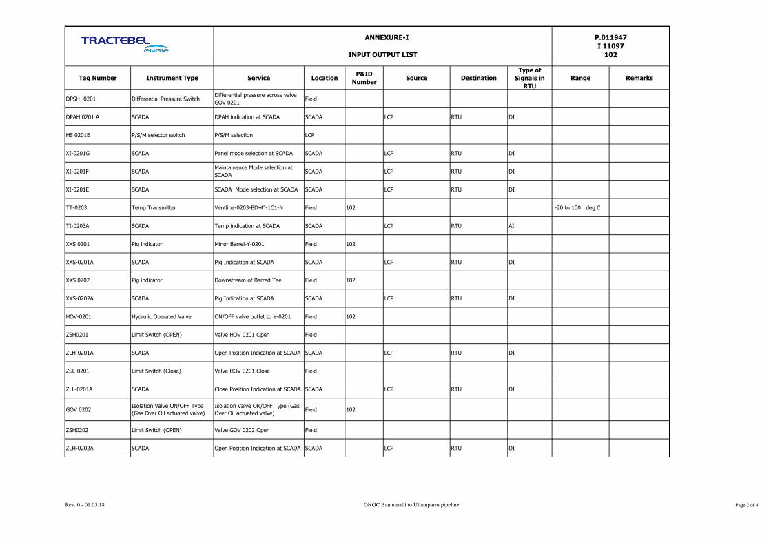
Tag Number Instrument Type Service LocationP&ID
NumberSource Destination
Type of
Signals in
RTU
Range Remarks
ANNEXURE-I
INPUT OUTPUT LIST
P.011947
I 11097
102
DPSH -0201 Differential Pressure SwitchDifferential pressure across valve
GOV 0201Field
DPAH 0201 A SCADA DPAH indication at SCADA SCADA LCP RTU DI
HS 0201E P/S/M selector switch P/S/M selection LCP
XI-0201G SCADA Panel mode selection at SCADA SCADA LCP RTU DI
XI-0201F SCADAMaintainence Mode selection at
SCADASCADA LCP RTU DI
XI-0201E SCADA SCADA Mode selection at SCADA SCADA LCP RTU DI
TT-0203 Temp Transmitter Ventline-0203-BD-4"-1C1-N Field 102 -20 to 100 deg C
TI-0203A SCADA Temp indication at SCADA SCADA LCP RTU AI
XXS 0201 Pig indicator Minor Barrel-Y-0201 Field 102
XXS-0201A SCADA Pig Indication at SCADA SCADA LCP RTU DI
XXS 0202 Pig indicator Downstream of Barred Tee Field 102
XXS-0202A SCADA Pig Indication at SCADA SCADA LCP RTU DI
HOV-0201 Hydrulic Operated Valve ON/OFF valve outlet to Y-0201 Field 102
ZSH0201 Limit Switch (OPEN) Valve HOV 0201 Open Field
ZLH-0201A SCADA Open Position Indication at SCADA SCADA LCP RTU DI
ZSL-0201 Limit Switch (Close) Valve HOV 0201 Close Field
ZLL-0201A SCADA Close Position Indication at SCADA SCADA LCP RTU DI
GOV 0202Isolation Valve ON/OFF Type
(Gas Over Oil actuated valve)
Isolation Valve ON/OFF Type (Gas
Over Oil actuated valve)Field 102
ZSH0202 Limit Switch (OPEN) Valve GOV 0202 Open Field
ZLH-0202A SCADA Open Position Indication at SCADA SCADA LCP RTU DI
Rev. 0 - 01.05.18 ONGC Bantumalli to Ullamparru pipeline Page 2 of 4

Tag Number Instrument Type Service LocationP&ID
NumberSource Destination
Type of
Signals in
RTU
Range Remarks
ANNEXURE-I
INPUT OUTPUT LIST
P.011947
I 11097
102
ZSL-0202 Limit Switch (Close) Valve GOV 0202 Close Field
ZLL-0202A SCADA Close Position Indication at SCADA SCADA LCP RTU DI
XSOV-0202A Open Solenoid Valve Valve GOV 0202 open command Field
HS-0202A SCADA Open command from SCADA SCADA RTU LCP DO
XSOV-0202B Close Solenoid Valve Valve GOV 0202 close command Field
HS-0202C SCADA Close command from SCADA SCADA RTU LCP DO
HS-0202F Local/Remote Selection switch Local/Remote selection Field
XI-0202G SCADA L/R indication at SCADA SCADA LCP RTU DI
DPSH -0202 Differential Pressure SwitchDifferential pressure across valve
GOV 0202Field
DPAH 0202 A SCADA DPAH indication at SCADA SCADA LCP RTU DI
HS 0202E P/S/M selector switch P/S/M selection LCP
XI-0202G SCADA Panel mode selection at SCADA SCADA LCP RTU DI
XI-0202F SCADAMaintainence Mode selection at
SCADASCADA LCP RTU DI
XI-0202E SCADA SCADA Mode selection at SCADA SCADA LCP RTU DI
Corrosion Monitoring
ProbeCMS system 0202-NG-12"-6C1-N LCP 0-10 MPY
CM-A SCADA CM indication at SCADA SCADA LCP RTU AI
GDS SYSTEM Gas detection system GDS system Control room 102 GDS RTU RS 485
LEL High Gas detection system GDS system Control room 102 GDS RTU DI Common alarm
LEL High High Gas detection system GDS system Control room 102 GDS RTU DI Common alarm
CMS SYSTEM
GAS DETECTION SYSTEM
Rev. 0 - 01.05.18 ONGC Bantumalli to Ullamparru pipeline Page 3 of 4

Tag Number Instrument Type Service LocationP&ID
NumberSource Destination
Type of
Signals in
RTU
Range Remarks
ANNEXURE-I
INPUT OUTPUT LIST
P.011947
I 11097
102
Sensor fault Gas detection system GDS system Control room 102 GDS RTU DI Common alarm
FDS SYSTEM Fire detection system FDS system Control room 102 FDS RTU RS 485
Zone-1 Fire detection system FDS system Control room 102 FDS RTU DI
Zone-2 Gas detection system GDS system Control room 102 GDS RTU DI
Zone-3 Gas detection system GDS system Control room 102 GDS RTU DI
Zone-4 Gas detection system GDS system Control room 102 GDS RTU DI
Zone-5 Gas detection system GDS system Control room 102 GDS RTU DI
Zone-6 Gas detection system GDS system Control room 102 GDS RTU DI
Sensor fault Gas detection system GDS system Control room 102 GDS RTU DI Common alarm
FC Stream-1 Flow computer-1 FC stream-1 Control room FC-1 RTU RS 485
FC Stream-2 Flow computer-2 FC stream-2 Control room FC-2 RTU RS 485
MA 0801 (Moisture
analyser)MA0801 MA0801
Control room /
FieldMA 0801 RTU RS 485
MA 0801 (Moisture
analyser)MA0801 MAHH0801
Control room /
FieldMAHH 0801 RTU DI
H2S 0801 (H2S analyser) H2S 0801 H2S0801Control room /
FieldH2S 0801 RTU RS 485
FIRE DETECTION SYSTEM
METERING SYSTEM
Rev. 0 - 01.05.18 ONGC Bantumalli to Ullamparru pipeline Page 4 of 4
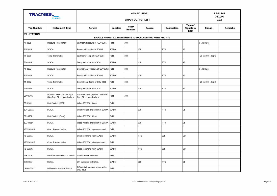
Tag Number Instrument Type Service LocationP&ID
NumberSource Destination
Type of
Signals in
RTU
Range Remarks
PT-0301 Pressure Transmitter Upstream Pressure of GOV 0301 Field 103 0-140 Barg
PI-0301A SCADA Pressure indication at SCADA SCADA LCP RTU AI
TT-0301 Temp Transmitter Upstream Temp of 1GOV 0301 Field 103 -20 to 100 deg C
TI-0301A SCADA Temp indication at SCADA SCADA LCP RTU AI
PT-0302 Pressure Transmitter Downstream Pressure of GOV 0302 Field 103 0-140 Barg
PI-0302A SCADA Pressure indication at SCADA SCADA LCP RTU AI
TT-0302 Temp Transmitter Downstream Temp of GOV 0301 Field 103 -20 to 100 deg C
TI-0302A SCADA Temp indication at SCADA SCADA LCP RTU AI
GOV 0301Isolation Valve ON/OFF Type
(Gas Over Oil actuated valve)
Isolation Valve ON/OFF Type (Gas
Over Oil actuated valve)Field 103
ZSH0301 Limit Switch (OPEN) Valve GOV 0301 Open Field
ZLH-0301A SCADA Open Position Indication at SCADA SCADA LCP RTU DI
ZSL-0301 Limit Switch (Close) Valve GOV 0301 Close Field
ZLL-0301A SCADA Close Position Indication at SCADA SCADA LCP RTU DI
XSOV-0301A Open Solenoid Valve Valve GOV 0301 open command Field
HS-0301A SCADA Open command from SCADA SCADA RTU LCP DO
XSOV-0301B Close Solenoid Valve Valve GOV 0301 close command Field
HS-0301C SCADA Close command from SCADA SCADA RTU LCP DO
HS-0301F Local/Remote Selection switch Local/Remote selection Field
XI-0301G SCADA L/R indication at SCADA SCADA LCP RTU DI
DPSH -0301 Differential Pressure SwitchDifferential pressure across valve
GOV 0301Field
ANNEXURE-I
INPUT OUTPUT LIST
P.011947
I-11097
102
SV -STATION
SIGNALS FROM FIELD INSTRUMENTS TO LOCAL CONTROL PANEL AND RTU
Rev. 0 - 01.05.18 ONGC Bantumalli to Ullamparru pipeline Page 1 of 2
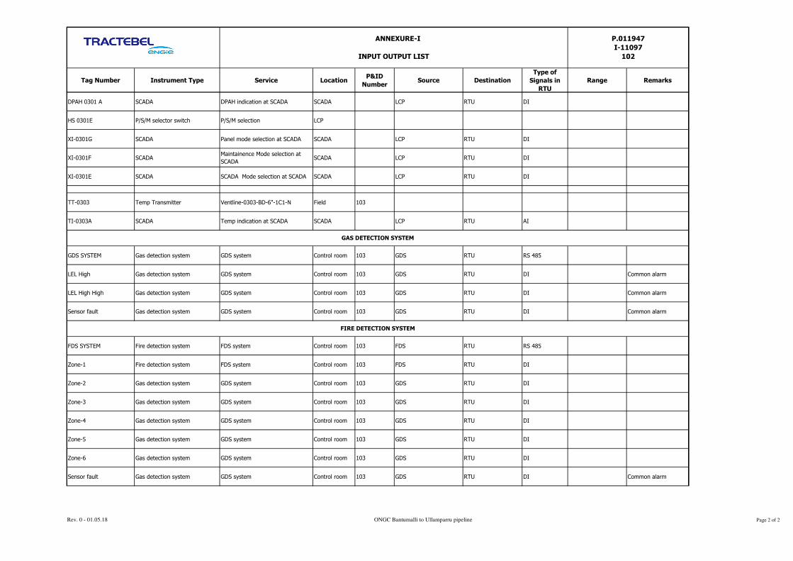
Tag Number Instrument Type Service LocationP&ID
NumberSource Destination
Type of
Signals in
RTU
Range Remarks
ANNEXURE-I
INPUT OUTPUT LIST
P.011947
I-11097
102
DPAH 0301 A SCADA DPAH indication at SCADA SCADA LCP RTU DI
HS 0301E P/S/M selector switch P/S/M selection LCP
XI-0301G SCADA Panel mode selection at SCADA SCADA LCP RTU DI
XI-0301F SCADAMaintainence Mode selection at
SCADASCADA LCP RTU DI
XI-0301E SCADA SCADA Mode selection at SCADA SCADA LCP RTU DI
TT-0303 Temp Transmitter Ventline-0303-BD-6"-1C1-N Field 103
TI-0303A SCADA Temp indication at SCADA SCADA LCP RTU AI
GDS SYSTEM Gas detection system GDS system Control room 103 GDS RTU RS 485
LEL High Gas detection system GDS system Control room 103 GDS RTU DI Common alarm
LEL High High Gas detection system GDS system Control room 103 GDS RTU DI Common alarm
Sensor fault Gas detection system GDS system Control room 103 GDS RTU DI Common alarm
FDS SYSTEM Fire detection system FDS system Control room 103 FDS RTU RS 485
Zone-1 Fire detection system FDS system Control room 103 FDS RTU DI
Zone-2 Gas detection system GDS system Control room 103 GDS RTU DI
Zone-3 Gas detection system GDS system Control room 103 GDS RTU DI
Zone-4 Gas detection system GDS system Control room 103 GDS RTU DI
Zone-5 Gas detection system GDS system Control room 103 GDS RTU DI
Zone-6 Gas detection system GDS system Control room 103 GDS RTU DI
Sensor fault Gas detection system GDS system Control room 103 GDS RTU DI Common alarm
GAS DETECTION SYSTEM
FIRE DETECTION SYSTEM
Rev. 0 - 01.05.18 ONGC Bantumalli to Ullamparru pipeline Page 2 of 2

Tag Number Instrument Type Service LocationP&ID
NumberSource Destination
Type of
Signals in
RTU
Range Remarks
PT-0401 Pressure Transmitter Upstream Pressure of GOV 0401 Field 104 0-100 Barg
PI-0401A SCADA Pressure indication at SCADA SCADA LCP RTU AI
TT-0401 Temp Transmitter Upstream Temp of 1GOV 0401 Field 104 -20 to 100 deg C
TI-0401A SCADA Temp indication at SCADA SCADA LCP RTU AI
PT-0402 Pressure Transmitter Downstream Pressure of GOV 0402 Field 104 0-100 Barg
PI-0402A SCADA Pressure indication at SCADA SCADA LCP RTU AI
TT-0402 Temp Transmitter Downstream Temp of GOV 0401 Field 104 -20 -100 deg C
TI-0402A SCADA Temp indication at SCADA SCADA LCP RTU AI
GOV 0401Isolation Valve ON/OFF Type
(Gas Over Oil actuated valve)
Isolation Valve ON/OFF Type (Gas
Over Oil actuated valve)Field 104
ZSH0401 Limit Switch (OPEN) Valve GOV 0401 Open Field
ZLH-0401A SCADA Open Position Indication at SCADA SCADA LCP RTU DI
ZSL-0401 Limit Switch (Close) Valve GOV 0401 Close Field
ZLL-0401A SCADA Close Position Indication at SCADA SCADA LCP RTU DI
XSOV-0401A Open Solenoid Valve Valve GOV 0401 open command Field
HS-0401A SCADA Open command from SCADA SCADA RTU LCP DO
XSOV-0401B Close Solenoid Valve Valve GOV 0401 close command Field
HS-0401C SCADA Close command from SCADA SCADA RTU LCP DO
HS-0401F Local/Remote Selection switch Local/Remote selection Field
XI-0401G SCADA L/R indication at SCADA SCADA LCP RTU DI
ANNEXURE-I
INPUT OUTPUT LIST
P.011947
I 11097
102
Receiving Station, ULLAMPARRU
SIGNALS FROM FIELD INSTRUMENTS TO LOCAL CONTROL PANEL AND RTU
Rev. 0 - 01.05.18 ONGC Bantumalli to Ullamparru pipeline Page 1 of 3

Tag Number Instrument Type Service LocationP&ID
NumberSource Destination
Type of
Signals in
RTU
Range Remarks
ANNEXURE-I
INPUT OUTPUT LIST
P.011947
I 11097
102
DPSH -0401 Differential Pressure SwitchDifferential pressure across valve
GOV 0401Field
DPAH 0401 A SCADA DPAH indication at SCADA SCADA LCP RTU DI
HS 0401E P/S/M selector switch P/S/M selection LCP
XI-0401G SCADA Panel mode selection at SCADA SCADA LCP RTU DI
XI-0401F SCADAMaintainence Mode selection at
SCADASCADA LCP RTU DI
XI-0401E SCADA SCADA Mode selection at SCADA SCADA LCP RTU DI
TT-0403 Temp Transmitter Ventline-0401-BD-4"-1C1-N Field 104
TI-0403A SCADA Temp indication at SCADA SCADA LCP RTU AI
XXS 0401 Pig indicator Minor Barrel-Y-0401 Field 104
XXS-0401A SCADA Pig Indication at SCADA SCADA LCP RTU DI
XXS 0402 Pig indicator Downstream of Barred Tee Field 104
XXS-0402A SCADA Pig Indication at SCADA SCADA LCP RTU DI
HOV-0401 Hydrulic Operated Valve ON/OFF valve outlet to Y-0401 Field 104
ZSH0401 Limit Switch (OPEN) Valve HOV 0401 Open Field
ZLH-0401A SCADA Open Position Indication at SCADA SCADA LCP RTU DI
ZSL-0401 Limit Switch (Close) Valve HOV 0401 Close Field
ZLL-0401A SCADA Close Position Indication at SCADA SCADA LCP RTU DI
Corrosion Monitoring
ProbeCMS system 0402-NG-12"-6C1-N LCP 104 0-10 MPY
CM-A SCADA CM indication at SCADA SCADA LCP RTU AI
CMS SYSTEM
GAS DETECTION SYSTEM
Rev. 0 - 01.05.18 ONGC Bantumalli to Ullamparru pipeline Page 2 of 3

Tag Number Instrument Type Service LocationP&ID
NumberSource Destination
Type of
Signals in
RTU
Range Remarks
ANNEXURE-I
INPUT OUTPUT LIST
P.011947
I 11097
102
GDS SYSTEM Gas detection system GDS system Control room 104 GDS RTU RS 485
LEL High Gas detection system GDS system Control room 104 GDS RTU DI Common alarm
LEL High High Gas detection system GDS system Control room 104 GDS RTU DI Common alarm
Sensor fault Gas detection system GDS system Control room 104 GDS RTU DI Common alarm
FDS SYSTEM Fire detection system FDS system Control room 104 FDS RTU RS 485
Zone-1 Fire detection system FDS system Control room 104 FDS RTU DI
Zone-2 Gas detection system GDS system Control room 104 GDS RTU DI
Zone-3 Gas detection system GDS system Control room 104 GDS RTU DI
Zone-4 Gas detection system GDS system Control room 104 GDS RTU DI
Zone-5 Gas detection system GDS system Control room 104 GDS RTU DI
Zone-6 Gas detection system GDS system Control room 104 GDS RTU DI
Sensor fault Gas detection system GDS system Control room 104 GDS RTU DI Common alarm
FC Stream-1 Flow computer-1 FC stream-1 Control room FC-1 RTU RS 485
FC Stream-2 Flow computer-2 FC stream-2 Control room FC-2 RTU RS 485
FIRE DETECTION SYSTEM
METERING SYSTEM
Rev. 0 - 01.05.18 ONGC Bantumalli to Ullamparru pipeline Page 3 of 3

1 AI(4-20mA) Analog input 6 1.5 8
2 DI(24 V DC) Digital Input 29 7.25 37
3 DO(24 V DC) Digital output 4 1 5
4 ModbusModbus serial master
port 6 1.5 8
1 AI(4-20mA) Analog input card 5 1.25 7
2 DI(24 V DC) Digital Input card 17 4.25 22
3 DO(24 V DC) Digital output card 2 0.5 3
4 Modbus Modbus serial master
port 2 0.5 3
1 AI(4-20mA) Analog input card 6 1.5 8 19
Total
Input Output
ChannelsRemarks
Remarks
Total Input / output
in RTUType
Input Output
ChannelsTypeSl. No.
Total
Total
Input Output
Channels
NEW RTU- SV STATION
Sl. No.Total Input / output
in RTU
spare 25%
spare 25%
Sl. No.
P.011947
I-11097
102
Total Input / output
in RTU
EXISTING RTU ULLAMPARRU STATION
spare 25%
Spare in Existing RTU
ANNEXURE II
TYPICAL I/O COUNTS DETAILS FOR RTU SYSTEM
Type
NEW RTU - BANTUMALLI STATION
Rev. 0 - 01.05.18 ONGC Bantumalli to Ullamparru pipeline Page 1 of 2

P.011947
I-11097
102
ANNEXURE II
TYPICAL I/O COUNTS DETAILS FOR RTU SYSTEM
2 DI(24 V DC) Digital Input card 21 5.25 27
15 (supply one number 32 DI
cards)
3 DO(24 V DC) Digital output card 2 0.5 3 4
4 ModbusModbus serial master
port 4 1 5 6
1 In addition to above, RTU shall have dual ethernet communication port for telecom modem , dedicated diagnostic and USB port etc.
2 Modbus serial port RS 485 shall be master and slave configruable
3 Modbus serial port RS 485/RS232 shall be configruable either RS 485 or RS 232
4
Note
Spare slot shall be compatible/configurable for inserting all type of cards as analog input, analog output , digital input or digital
out cards or modbus
Rev. 0 - 01.05.18 ONGC Bantumalli to Ullamparru pipeline Page 2 of 2

PTS – TELECOMMUNICATION
SYSTEM
P.011947
I-11097
103
ONGC BANTUMILLI TO ULLAMPARU PIPELINE KG
BASIN
TRACTEBEL ENGINEERING PVT. LTD.
PTS – TELECOMMUNICATION SYSTEM
DOC. NO. P.011947 I 11097 103
0 01.05.2018 Issued for Procurement AS SK SKH
REV. DATE Subject of Revision Prepared By Checked By Approved By

PTS – TELECOMMUNICATION
SYSTEM
P.011947
I-11097
103
Rev. 0 ONGC Bantumalli to Ullamparru pipeline Page 1 of 1
TABLE OF CONTENTS
1.0 INTRODUCTION .................................................................................................................... 1
2.0 REFERENCE ........................................................................................................................... 1
3.0 PROJECT BRIEF ..................................................................................................................... 1
4.0 POWER SUPPLY .................................................................................................................... 1
5.0 ENVIRONMENTAL SPECIFICATIONS .................................................................................... 1
6.0 SCOPE OF WORK ................................................................................................................... 1
7.0 TECHNICAL SPECIFICATIONS .............................................................................................. 2
8.0 SURVEILLANCE CCTV SYSTEM .............................................................................................. 7
9.0 INSTALLATION, TESTING AND COMMISSIONING ............................................................... 9
10.0 FACTORY ACCEPTANCE TEST (FAT) .................................................................................... 10
11.0 SITE ACCEPTANCE TEST (SAT) ........................................................................................... 12
12.0 TEST DOCUMENTATION ...................................................................................................... 13
13.0 TEST EQUIPMENT ............................................................................................................... 13
14.0 DOCUMENTATION .............................................................................................................. 13

PTS – TELECOMMUNICATION
SYSTEM
P.011947
I-11097
103
Rev. 0 ONGC Bantumalli to Ullamparru pipeline Page 1 of 13
1.0 INTRODUCTION
1.1 These specifications outline the requirements of Telecommunications system, comprises of SDH Telecom unit,
CCTV and Analog phone other accessories for this project
2.0 REFERENCE
This document shall be read in conjunction with scope of work C&I and material requisition.
3.0 PROJECT BRIEF
3.1 The entire project is comprised of dispatch station, receiving station and remote operated SV stations along
with associated instrumentation and protection system. Refer P&ID for detail.
3.2 There is an existing Network Management system for the existing OFC based telecommunications system. The
new OFC based telecom system on route shall integrate with the existing NMS for monitor of system
parameters from Master Station.
3.3 New SDH STM 4 telecom system along with cabinet shall be installed at despatch and SV station. Existing
SDH will be used at ullamparru.
3.4 Two number CCTV cameras (one fixed and one PTZ) shall be installed at all stations. Video surveillance
system for monitor new sites on the pipeline route. The existing CCTV Server shall be utilized and extended to
the new CCTV cameras with some modification if required.
3.5 Analog phones one number in control room and one number in guard room and one number Ex proof WP 64 in
field with three side canopy (despatch & receiving). One set of FXO & FXS is required for voice
communication.
3.6 New 24C optical fiber is laid from Bantumalli, SV and Ullamparru stations. New OFC shall be interfaced with
existing system at Ullamparru.
4.0 POWER SUPPLY
Electrical power supply 230 V AC, 24 V DC and 48 V DC UPS power supply will be given at one point
(AC/DC PDB) and from there vendor shall lay power cable upto to the require place. Further distribution shall
be in the scope of the vendor. If any other voltage levels are required, then all necessary conversions shall be in
the scope of vendor.
5.0 ENVIRONMENTAL SPECIFICATIONS
All equipment shall be designed for operation, storage and transportation under the following environmental
condition:
Max. / Min. Temperature 0 °C / 55 °C
Design temperature (-) 20 °C to 60 °C
Relative Humidity 95%
Hazardous Area Classification Zone 2, Gas Group II A or B, Temp. Class
T 3
Control Room & Electrical Room Safe Area
6.0 SCOPE OF WORK
6.1 Optical Fiber based SDH Communications System STM-4, where SDH (STM-4) shall form the backbone. The
flat ring based on dual optical fiber pair, shall be possible with all the stations on gas pipeline. These STM-4
nodes will be configured as ADM-node. The ring, if facilitated, shall be based on a sequential network
topology with a redundant path. The proposed system shall use the latest technological advancements in SDH

PTS – TELECOMMUNICATION
SYSTEM
P.011947
I-11097
103
Rev. 0 ONGC Bantumalli to Ullamparru pipeline Page 2 of 13
networks such as Virtual Concatenation (VCAT) and Link Capacity Adjustment Scheme (LCAS). SNCP
protection should be supported.
6.2 The scope of work for the contractor shall be turnkey supply, erection, testing and commissioning of Optical
Fiber based SDH, (STM-4) telecom system on new sites in such a way that the complete network is suitably
integrated to monitor the parameters of the new and existing telecom system from a common place.
6.3 Supply, installation, testing and commissioning of CCTV with all required accessories. This shall be integrated
with existing CCTV system for monitoring from Master Station.
6.4 All accessories like DC Power supply, encoder, surge protectors, cables and connectors etc required for the
CCTV cameras shall be in contractor’s scope.
6.5 The system shall be warranted against any malfunction for a defined period anywhere in tender document after
commissioning of the system. The vendor shall rectify the problem, including replacement wherever required
within the cost of the project.
6.6 The existing OFC based telecom system shall be studied in depth and details so that the new OFC based
telecom system and the existing OFC based telecom system are integrated to form a single network to monitor
the system parameters of the telecom system from a common site.
6.7 Gathering information after detailed survey, if required for complete system design & detailed engineering to
meet the overall system availability objectives.
6.8 Detailed design & link engineering based on the Optical Fibre Characteristics and hop lengths
6.9 Co-ordination with SCADA vendor during engineering phase and also during integration, installation and
commissioning phase of the project.
6.10 The vendor shall be fully responsible for detailed engineering and design of the proposed system. The vendor
shall design the network in a scalable fashion so as to support the future bandwidth and service needs. The
vendor shall provide full details of the network design & engineering (all parameters) in the bid proposal with
regard to following, in line with specifications, requirements & design guidelines:
• Optical Link Engineering Hop-wise.
• Network Management of SDH elements.
• SCADA polling.
• Network Synchronization.
6.11 The network shall be configured, equipped & integrated to ensure smooth & efficient operation of SCADA
system including other facilities like voice, data and Video surveillance system. The details mentioned are
indicative. Hence, the vendor shall take all necessary actions and supply all required interfaces for fulfilling the
overall requirement of the tender within quoted cost.
7.0 TECHNICAL SPECIFICATIONS
7.1 STM-4 HIGH CAPACITY SDH MULTISERVICE SYSTEM
1) The System should be a carrier grade platform, to provide a scalable high capacity STM-4 backbone.
The system should be able to support whole new breed of functionalities for efficiently aggregating,
switching and managing a mix of global services ranging from lower speed electrical E-1, E-3 line
service, through high-speed optical STM-4 services. The platform is envisaged to support next-
generation data capabilities for both Ethernet services (10/100 Base T, 100FX, GE and 10GE). The
system shall also support PDH service for multiplexer interface on the pipeline route.
2) System at all the locations should be equipped with add- drop multiplex facility with a Fully Non–
Blocking Cross Connect Switch Matrix of STM-1 equivalents (HO level) in the same shelf. Complete
Switch Matrix including HO & LO should be 1+1 protected.
3) The equipment should also support direct termination of E1 interfaces from main shelf. In case of a
separate shelf required for such terminations, the vendor should offer equipment along with such shelf at
all the locations. The termination shelf shall not be considered a part of the Switch matrix cross connect
requirements of the main shelf.
PTS – TELECOMMUNICATION
SYSTEM
P.011947
I-11097
103
Rev. 0 ONGC Bantumalli to Ullamparru pipeline Page 3 of 13
4) The Switch Matrix should support completely non-blocking Trib-to-Trib, Line–to–Line, Trib. to Line
and Line to Trib connections.
5) It is required that the equipment supports Virtual Concatenation to support Data Interfaces. Also the
equipment shall support LCAS feature to enable dynamic allocation of Bandwidth.
6) The system shall provide DCC transparency to enable the passing of the DCC channels of other
Vendor’s system without any blocking.
7) The system should provide Visual power on indication as well as the card level Visual indications for
status of individual cards. Following should be indicated:
• LOS Indication
• Card Active Indication
• Card Status Indication
8) The equipment is required to support a variety of tributary interfaces with details as listed below:
• GBE
• E3
• E1
• 10/100/1000 Base T
9) Vendor shall indicate port densities of each type of interfaces and maximum density per shelf.
10) The offered Equipment shall support SFP modules.
11) UPGREADABILITY: All SDH equipments should be upgradeable to full STM-16. All regenerator sites
should be equipped with same size of cross connector.
All Optical interfaces and Electrical Interfaces should comply with ITU-T G.957/ G.691 requirements.
The Electrical interfaces should be in line with G.703.
12) WINDOW OF OPERATION: All Optical Interfaces should work on 1550nm or 1310nm optical
window. For data interfaces like GBE (Gigabit Ethernet) catering to enterprise requirements, operation
in 850 nm (SX) shall also be supported. It shall be possible to mix the 1000 Base SX and LX SFP
modules within the same card.
7.2 NETWORK TOPOLOGY
The equipment should support various network topologies as listed below:
• Multiple Rings
• Hubbed-Rings
• Star
• Meshed-rings
• Point-to-Point
• Linear Chains.
The equipment should support all possible topology requirements and should be capable of being configured as
a Terminal, ADM. The equipment is envisaged to serve as integrated platform for high capability SDH links.
7.3 NETWORK PROTECTION
The equipment should be able to support various protection schemes, SNCP, MS-Spring, 1+1 MSP etc. The
equipment should be configurable for both protected as well as unprotected services. SNCP at STM-1 level and
at all tributary level of E-1 / E-3 etc. is a mandatory requirement and shall be provided. Equipment should also
support 1+1 MSP and MS-spring at STM-4 level and it should be possible to configure unprotected linear
chains at all STM hierarchies.

PTS – TELECOMMUNICATION
SYSTEM
P.011947
I-11097
103
Rev. 0 ONGC Bantumalli to Ullamparru pipeline Page 4 of 13
7.4 EQUIPMENT PROTECTION
All the traffic affecting common units shall be 1+1 protected, which essentially includes Switch Matrix and
Power Supply. Shelf processor or controller should also be protected in case its failure is traffic affecting.
All Optical interfaces STM-1/4 should be protected using SNCP and should have the capability of supporting
1+1 MSP protection to have card level redundancy.
7.5 ATTENUATION
The network should be designed in accordance with the fiber attenuation and other optical link parameters
mentioned as part of the design requirements mentioned in the tender. A Link budget calculation for all optical
links in the network should be provided by the vendor. The design shall clearly define the margin with respect
to the sensitivity of the receiver for each of the fiber links. The same should clearly indicate the type of
interfaces used for a certain link.
7.6 EMBEDDED CHANNEL
The equipment should be managed by using embedded DCC bytes of STM-4/ STM-16 frame as prescribed in
the frame structure of STM-4 in ITU-T. The equipment should support auxiliary Ethernet channel over DCC to
carry other in station data to facilitate External DCN.
Any External DCN equipment required should be clearly indicated with a connectivity plan.
7.7 General Requirements
The SDH transmission equipment shall be a Next-Generation (NG) -MSPP optics system capable of
transporting both circuit based TDM traffic as well as packet based data traffic. It shall be capable of
supporting SDH (STM-4/STM-16), PDH (E1/E3) and Ethernet (FE/GE) traffic in a single unit/chassis. It shall
provide the key functionality as mentioned in this chapter.
The SDH equipment to be supplied by the vendor shall be compatible with the system already working on the
sites
7.8 Add Drop Multiplexer (ADM)
The SDH equipment shall be modular and shall support the drop and insert of various SDH streams on one
single platform. It shall support the following features:
a) Support for STM-4/STM-16 interfaces with detailed capability as specified under technical specification
of optical interfaces.
b) Capable of supporting regeneration in the same platform.
c) Deployable as linear, ring or mesh topologies.
d) E1, E3 as PDH interfaces
e) 10/100base FE and 1000 base GigE as Ethernet.
7.9 Cross Connect Capacity of ADM
The SDH equipment shall support an integrated fully non-blocking cross connect capability. It shall support the
following features:
a) Equipment should be equipped with a Fully Non–Blocking Cross Connect Switch Matrix of minimum
16 x 16 STM-1 bi-directional at HO (higher order) VC-4 level as well as at lower order (LO) at VC-3,
VC-12 level. Equipment should support non-blocking cross-connect without any blocking of traffic on
VC-12, VC-3 and VC-4 level.
b) The System shall support full low order (VC-12) connectivity and it shall allow direct mapping of any 2
Mbps into any STM-16/STM-4 aggregate and interconnect VC-12 signals among the equipped STM
interfaces without any blockage at any level in the equipment.
7.10 Optical Interfaces
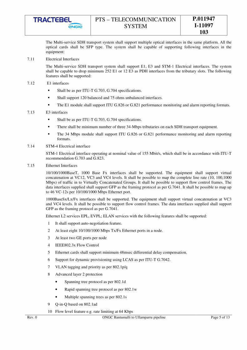
PTS – TELECOMMUNICATION
SYSTEM
P.011947
I-11097
103
Rev. 0 ONGC Bantumalli to Ullamparru pipeline Page 5 of 13
The Multi-service SDH transport system shall support multiple optical interfaces in the same platform. All the
optical cards shall be SFP type. The system shall be capable of supporting following interfaces in the
equipment:
7.11 Electrical Interfaces
The Multi-service SDH transport system shall support E1, E3 and STM-1 Electrical interfaces. The system
shall be capable to drop minimum 252 E1 or 12 E3 as PDH interfaces from the tributary slots. The following
features shall be supported:
7.12 E1 interfaces
Shall be as per ITU-T G.703, G.704 specifications.
Shall support 120 balanced and 75 ohms unbalanced interfaces.
The E1 module shall support ITU G.826 or G.821 performance monitoring and alarm reporting formats.
7.13 E3 interfaces
Shall be as per ITU-T G.703, G.704 specifications.
There shall be minimum number of three 34-Mbps tributaries on each SDH transport equipment.
The 34 Mbps module shall support ITU G.826 or G.821 performance monitoring and alarm reporting
formats.
7.14 STM-4 Electrical interface
STM-1 Electrical interface operating at nominal value of 155 Mbit/s, which shall be in accordance with ITU-T
recommendation G.703 and G.823.
7.15 Ethernet Interfaces
10/100/1000BaseT, 1000 Base Fx interfaces shall be supported. The equipment shall support virtual
concatenation at VC12, VC3 and VC4 levels. It shall be possible to map the complete line rate (10, 100,1000
Mbps) of traffic in to Virtually Concatenated Groups. It shall be possible to support flow control frames. The
data interfaces supplied shall support GFP as the framing protocol as per G.7041. It shall be possible to map up
to 46 VC-12s per 10/100/1000 Mbps Ethernet port.
1000BaseSx/Lx/Fx interfaces shall be supported. The equipment shall support virtual concatenation at VC3
and VC4 levels. It shall be possible to support flow control frames. The data interfaces supplied shall support
GFP as the framing protocol as per G.7041.
Ethernet L2 services EPL, EVPL; ELAN services with the following features shall be supported:
1 It shall support auto-negotiation feature.
2 At least eight 10/100/1000 Mbps Tx/Fx Ethernet ports in a node.
3 At least two GE ports per node
4 IEEE802.3x Flow Control
5 Ethernet cards shall support minimum 48msec differential delay compensation.
6 Support for dynamic provisioning using LCAS as per ITU-T G.7042.
7 VLAN tagging and priority as per 802.1p/q
8 Advanced layer 2 protection
• Spanning tree protocol as per 802.1d
• Rapid spanning tree protocol as per 802.1w
• Multiple spanning trees as per 802.1s
9 Q-in-Q based on 802.1ad
10 Flow level feature e.g. rate limiting at 64 Kbps
PTS – TELECOMMUNICATION
SYSTEM
P.011947
I-11097
103
Rev. 0 ONGC Bantumalli to Ullamparru pipeline Page 6 of 13
11 8 class of services per egress port with SP, WRR, WFQ scheduling scheme
12 VLAN, MAC learning and forwarding
13 Security based on access control list
14 OAM features EFM (802.3ah) and CFM (802.1ag)
7.16 SYNCRONIZATION:
Clocks shall be as per ITU – T recommendation & network synchronization of the SDH equipment shall
conform to, where ever applicable, ITU-T recommendation G.781.
The SDH (STM-4) equipment should have a minimum one Input & minimum one output Synch Interfaces.
The SDH equipment should provide a 2MHz clock from the system.
The equipment should be capable to synchronize from:
a) External clocks b) Any STM-N c) 2 Mb/s interface d) Internal clock .
The synchronization shall be as per the following specifications:
Compliance with ITU-T G.813 standard for clock accuracy.
Compliance with ITU-T G.811, G.812 and G.813 standards for minimum free-run accuracy, SDH jitter
and wander and holdover stability.
7.17 PIGTAIL & CONNECTORS TO BE USED IN THE FTC:
This specification provides requirements for single mode fibre pigtails and connectors. They should meet the
ITU-T recommendations G-652 & G 655 as required.
Both connectors and cables should be robust and should withstand wear and tear due to frequent use,
connection and disconnection. Normal expected life should be 15 years or more.
7.18 OPTICAL PATCH CORDS
Make : Birla-3M/ Cancam/ Advanced Fiber System, Corning
OPTICAL PARAMETERS: (in line with the cable specifications provided in this bid document)
The patch chords provided shall be 20 Mtr. in length
Insertion loss : Maximum 0.3 dB per connector plus fibre loss
Return loss : Better than 40 dB
Temperature Dependency : < 0.3 dB from – 20 to + 60
Change in connection loss
With passage of time at
60 °C for 100 hrs : it should be < 0.3 dB
Change in connection loss
Due to vibration : < 0.05 dB
Reproducibility of
Connection loss by repeated
Connections and : < 0.3 dB
Disconnection for 500 times.
Change in Connection loss
In relation to Tensile strength : (1) Loaded : – 50 dB
(2) Unloaded : – 30 dB

PTS – TELECOMMUNICATION
SYSTEM
P.011947
I-11097
103
Rev. 0 ONGC Bantumalli to Ullamparru pipeline Page 7 of 13
7.19 Engineering order wire (EOW) for SDH equipment
STM 4 equipment shall provide EOW with connection to the E1 or E2 byte of STM SOH. The EOW channel
shall be connecting all telecom stations on selective and on call basis and shall have such features as ring back
tone, dial tone. Suitable phones for the EOW shall be provided as part of the telecom racks itself.
Equipment vendor to ensure that dial tone and ring back tone shall be available in EOW’s.
8.0 SURVEILLANCE CCTV SYSTEM
8.1 General
CONTRACTOR shall engineer, supply, install, test and commission the CCTV system at the allocated facilities
along the pipeline. The purpose of the CCTV System will be to inform operators of “intruders” at the facilities
and to cover process systems of importance to the daily running of the pipeline operation by:
• Installing cameras to monitor the stations, for visual monitor of daily running of the process system.
• Installing cameras to monitor the remote stations, block valves stations for operation status condition
• Enabling priority control of cameras within the pipeline facilities to follow intruder at the specific
location.
• After incident to return cameras to their fixed pre-set condition.
• The cameras shall utilize existing CCTV Server with recording facility.
8.2 CCTV Requirements
The requirement of explosion proof cameras is in extension of the existing cameras with the excising servers.
The vendor shall ensure that the camera is compatible with the existing system for monitor of site condition and
also being able to store the information. The vendor has to ensure that the interfaces, DC power sources, surge
protectors, encoders L-2 switches etc are provided as per the requirement of each of the sites.
8.3 CCTV System Descriptions
The CCTV system has already been in operation of the existing pipeline route. All the sites have been provided
with CCTV cameras which is explosion proof type considering the areas of its use.
The explosion proof camera assembly shall be equipped with motorized zoom lens and wash/wipe
facilities. The camera assembly shall be manufactured from a non-corrosive material and be suitable for
continuous tropical weather environment. Each camera assembly shall be weather-proof or ATEX
certification CAT 2 depending on the hazardous area they are located and ingress protected to a minimum
of IP65.
Low light performance camera with auto iris Light sensitivity when equipped with a 10 to (16mm-160mm)
zoom lens of 0.01 LUX at the scene of illumination camera shall maintain normal video output of 1
volt peak to peak at within 12 dB of specified signal to noise ratio.
Each camera assembly shall be provided with an intermediate junction box, which shall be certified
and protected to the same level as the camera and pan/tilt unit. This junction box shall allow termination
of control and power cables.
The cabling arrangements to each camera assembly shall be arranged so as to minimize the requirements for
special cables. In order to achieve this it is anticipated that a minimum of one power cable and one
control cable will be required per camera. It is preferred that one fibre optic connection and power cable be
supplied to each camera.
The camera housing shall incorporate a sun hood.
Wash wipe facilities shall comprise the wash wipe mechanism incorporated into the camera housing;
water feed system to the mechanism and water reservoir providing a minimum of 10 litre capacity. The
water reservoir shall be suitable for installation at lower level such that it is easily accessible for
maintenance/recharging.
8.4 Motion Detection and Intrusion Warning

PTS – TELECOMMUNICATION
SYSTEM
P.011947
I-11097
103
Rev. 0 ONGC Bantumalli to Ullamparru pipeline Page 8 of 13
The motion detection cameras shall either have frame store at the camera or motion detection
capabilities installed at the video mux that shall allow surveillance systems that utilise advanced digital
video compression techniques that give the best quality picture and video performance. Motion detection
shall be configured individually for each camera.
Either method of motion detection is acceptable; CONTRACTOR shall propose the specifications for each
system and to provide an acceptable method for the project. Cameras equipped with Intrusion warning shall
be used for Access Control only.
On activation, the cameras shall initiate a signal to be transmitted to MCS and that shall activate the CCTV
monitor screens and produce an audible/visual alarm for operations use. This action is immediate alert the
Control Room operators immediately of an intrusion.
In situations when the facility is “manned” by the pipeline maintenance team, operators shall be allowed to
isolate all cameras from reporting the alarms. This will ensure the operators are not disturbed by unwanted
alarms.
On leaving the unmanned facility, after completion of task, the cameras and the CCTV system shall be
re-armed and shall return to normal reporting.
8.5 Video Recording Unit
Each facility shall be installed with a remote video unit that shall allow remote management and recording
of the total camera system.
The local video unit shall ensure recorded images are stored on a Raid hard-drive using different types of
CODEC using compression rates of either MPEG2 or MPEG4 depending on the picture quality required.
The system shall be able to record all cameras at the same time. Special consideration shall be placed on the
stored image activated by the video detection at the camera. Watermarking of any stored image shall ensure
that tampering of images is identified. Each unit shall have multiple alarm inputs.
The local central unit shall also establish the communication between the stations server in the
Communication Room and MCR. Connection to data sources shall allow efficient standard MPEG video
techniques to be used over the SDH fibre optic links
The main interface to MCR and stations CCTV system shall be via Ethernet. Each facility shall have a video
hub/switch that shall interface the local central unit to the SDH for communication back to MCR.
8.6 Camera
CONTRACTOR shall supply and install the camera at the following facility as minimum at all sites on
Raageshwari - Palanpur route.
Cameras shall be solid state CCD type with the following, minimum specifications:
Pick up tube : Charge Coupled Device (CCD), 752 x 582
Pixels Sensitivity : 0.01 lux (high sensitivity)
Resolution : ≥470 Lines (horizontal, centre) standard : PAL/NTSC
Rotating Angle : Pan - approximately 360º, Tilt – approximately 180º
Zoom : Minimum 18x optical and 12x digital
ID Generator : Minimum 16 Characters
All Cameras shall be supplied complete with the following:
• 316L stainless steel explosion proof housing or equivalent, suitable for outdoor tropical weather
environments, shall be certified ATEX Cat 2 or 3 depending on the hazardous area they are
located in and complete with integral anti-condensation heater.
• Zoom lens with motorised auto iris and neutral density filters to minimise ‘flaring’ or
damage due to bright lights. The zoom lens range, (typically 10:1), shall be chosen to ensure
adequate coverage of the required area and to minimise camera ‘shake’ at maximum zoom.
• Wash/Wipe facilities

PTS – TELECOMMUNICATION
SYSTEM
P.011947
I-11097
103
Rev. 0 ONGC Bantumalli to Ullamparru pipeline Page 9 of 13
8.7 Wash and Wipe
These shall meet the following minimum parameters: Reservoir capacity: at least 10 litres
Reservoir type : manually pressurized
Flow rate : > 0.5 litre per minute
8.8 CCTV Cable
The CCTV Main Distribution Frame (MDF) is where the main cable distribution is terminated to ensure
that each camera is fed individually. It is from this central point that the main cables to each camera for
the CCTV system will be developed.
The CCTV system cables shall start at the main CCTV MDF at each facility and from there a multimode
fibre optic cable shall be installed and terminate on junction boxes attached to each individual camera.
The fibre optic cable shall carry video information only. A separate multi-core copper cable and power
cable shall be installed to each camera for the zoom control and wash/wipe facilities.
All CCTV distribution cables shall be fire retardant. This requirement is for all cables associated with the
CCTV system including the power feed cables, fibre optic video cables and zoom, wash/wipe control cables.
All multi-core CCTV cables shall include 20% of spare pairs for future expansion.
8.9 CCTV Junction & Marshalling Boxes
All CCTV junction boxes shall be made of corrosion-resistant flameproof material, preferably fibreglass-
reinforced polyester or SS316.
• Protection mode : EEx “d”
• Environmental protection : IP 65
Each box shall be fitted with sufficient screw-type terminals to terminate all pairs and cable screens
used and unused. The terminal blocks shall be certified for use with the box. Each box shall be equipped
with certified cable glands/plugs and with an earthing bar. Junction boxes shall be equipped with Electrical
Safety earth bars.
Cable screen continuity shall be achieved through Junction box dedicated terminals. All CCTV junction
boxes shall include 30% of spare terminals for future expansion.
8.10 The vendor is to propose other accessories like Power supply, surge protection equipment, codec, media
converter, camera stand, camera wash screen, armored cable and accessories for a reliable and efficient
system operation.
9.0 INSTALLATION, TESTING AND COMMISSIONING
9.1 CONTRACTOR is responsible for integration, installation, inspection, testing and commissioning the
telecommunication system on full turnkey basis. All necessary tools, test equipment, consumable, installation,
testing and commissioning of the systems shall be provided.
9.2 CONTRACTOR shall assume final responsibility for the inspection and testing of the Telecommunications
system to ensure that the system conform to the requirements of the codes and standards specified in this
document.
9.3 Detail installation plan including procedures and schedules for accomplishing the work to address various
phases of implementation shall be submitted for review and approval.
9.4 CLIENT may appoint a third party inspection services for the Telecommunications system. The CLIENT’S
representative shall have free access to CONTRACTOR’S facility and those of all major
SUPPLIER/VENDOR’S facility at all times.
9.5 Inspection by CLIENT or his Inspector will in no way relieve CONTRACTOR of any of his responsibilities for
ensuring that the system supplied meets all the requirements of this document and its attachments.
9.6 Inspection and testing shall be carried out at the SUPPLIER/VENDOR’s work place and shall be witnessed by
CLIENT’S representative.

PTS – TELECOMMUNICATION
SYSTEM
P.011947
I-11097
103
Rev. 0 ONGC Bantumalli to Ullamparru pipeline Page 10 of 13
9.7 Based on this document, CONTRACTOR shall submit full testing procedure for factory testing, site testing and
acceptance procedure for CLIENT’S approval. For hardware, the procedures shall include purpose of test, test
definition of input, procedure, result expected, and acceptance criteria. For software, it shall include details of
the method, list of tests, sequence of execution, result expected, and acceptance criteria.
9.8 The testing and acceptance of the system shall be carried out on the mutually agreed procedures and criteria
based on this specification and SUPPLIER/VENDOR’s standard procedures.
9.9 CONTRACTOR shall identify in the project schedule hold points for CLIENT witnessed inspection/ test.
10.0 FACTORY ACCEPTANCE TEST (FAT)
10.1 The FAT shall be a thorough and complete functional test of the hardware and software of the entire
Telecommunications system.
10.2 CONTRACTOR shall conduct inspection after completion of all work, including equipment burn-in and pre-
FAT test performed as appropriate. Pre-FAT test report shall be submitted to the CLIENT prior to FAT.
CONTRACTOR shall give CLIENT advance notice of at least fifteen (15) working days before the FAT is
conducted.
10.3 CONTRACTOR shall demonstrate the functional integrity of the system hardware and software. No material or
equipment shall be transported until all required tests are successfully completed and certified ‘Ready for
Delivery’ by the CLIENT.
10.4 CLIENT reserves the right to be involved and satisfy himself at every stage of inspection. CLIENT shall be
free to request any specific test on any equipment considered necessary by him although not listed in this
specification.
10.5 CONTRACTOR shall note that acceptance of any equipment or the exemption of inspection or testing shall in
no way absolve CONTRACTOR of the responsibility for delivering the equipment, which meets all the
requirements specified in the specification.
10.6 The FAT shall be conducted CONTRACOR’S manufacturing facility. CONTRACTOR shall provide a room,
complete with acceptable office facilities and refreshments for the CLIENT’S representative(s) for the duration
of the FAT.
10.7 All tests shall be conducted utilizing only equipment that will eventually be shipped to the
10.8 Use of “replacement” units during any part of the FAT will not be allowed.
10.9 Any defects found during the FAT shall be rectified in the presence of the CLIENT. In the event this is not
possible, a checklist shall be prepared stating all outstanding items for approval by the CLIENT’S Inspector.
10.10 It shall be CONTRACTOR’S responsibility to modify and/or replace any hardware and modify the software if
the specified functions are not satisfactorily achieved during testing and factory acceptance.
10.11 The equipment shall not be shipped until all discovered defects have been rectified and satisfactorily re-
tested.
10.12 The following test shall be included into the FAT as a minimum:
a) Power Supply tests
b) Processor tests
c) Functional and signal tests
d) All communication interfaces
e) Electrical noise immunity
f) Radio Frequency Interference
g) Dimensional checks
The factory inspection shall be carried out as follows:

PTS – TELECOMMUNICATION
SYSTEM
P.011947
I-11097
103
Rev. 0 ONGC Bantumalli to Ullamparru pipeline Page 11 of 13
• CONTRACTOR shall perform in-house testing prior to CLIENT witnessed FAT to assure smooth
testing during the FAT.
• CONTRACTOR shall then systematically, fully, and functionally test all the hardware and software in
the presence of CLIENT’S representative/inspector. All systems shall be interconnected to simulate,
as close as possible, the total integrated Telecommunications system.
All hardware must be inspected for physically damaged components and general workmanship standards.
Particular note should be made of:
• Wiring looms and terminations
• Quality of earth and power connections
• Ease of access for maintenance work.
• Door seals and paint finish with reference to the final site environmental conditions.
• Printed circuit board connections to backplanes in card cage
• Plug and socket connections.
• Robustness of supports, frames, and circuit boards
A number of tests must be carried out on the completed system. The following tests are a minimum
requirement and shall be carried out on the total deliverable system hardware and software, including
commissioning spares. The system shall be fully configured to provide all functions as detailed in the
Specification. Any external system interfaces must be adequately simulated by CONTRACTOR equipment.
Shock Test and Vibration Test
During this inspection, a simple shock vibration test shall be carried out on a number of plugs, sockets,
terminal blocks, and printed circuit board backplane connections to ensure that a reliable and secure
connection is provided.
The shock test shall be performed on an operational system by tapping the aforementioned components with
an insulated device. Care shall be exercised so as not to damage the equipment. Any abnormal effect of the
system shall be investigated and rectified by CONTRACTOR.
Supply Power Variations
This test shall be conducted to verify the ability of the system to compensate for input power variations
without impairment of system performance.
The following power variations shall be applied on an operational system for a minimum of 20 minutes each.
System functional performance shall be monitored for abnormalities at the system displays and indicators:
a) Maximum specified voltage and nominal frequency.
b) Minimum specified voltage and nominal frequency.
c) Maximum specified frequency and nominal voltage.
d) Minimum specified frequency and nominal voltage.
e) Input power interruption with nominal voltage and frequency before and after interruption.
Functional Test
Functional testing is largely dependent on individual system requirements. The system shall be subjected to
tests sufficient to determine its compliance with all functional requirements specified in this Specification.
Maintenance and Calibration
Procedures specified by SUPPLIER/VENDOR in the maintenance manual(s) for maintenance and calibration
of equipment shall be carried out to ensure that all specified adjustments and other maintenance work could be
conducted in a safe and reliable manner.
Electrical Test

PTS – TELECOMMUNICATION
SYSTEM
P.011947
I-11097
103
Rev. 0 ONGC Bantumalli to Ullamparru pipeline Page 12 of 13
The following test shall be performed on all electrical and electronic modules and systems:
¾ Functional test of all electronic modules, test for short circuits, and test for ground faults.
¾ Verification that terminal and wiring coding is in accordance with the panel drawings.
System Failures
Tests shall be carried out in order to verify that redundant systems operate as specified, i.e. changeover to
back-up occurs correctly and is annunciated to the operator. Operator displays and diagnostics identifying the
particular failed sub-system shall be checked as sufficient. The following redundant sub-systems are typical.
a) Redundant Equipment
Where applicable, failures of main equipment in turn shall be simulated. Failures should be simulated:
• ¾ By interruption of the equipment power supply for sufficient duration to cause the equipment
reset condition.
• ¾ By manual reset of the equipment
• ¾ Check the auto activation of the back-up equipment.
b) Redundant Power Supplies
Failures on each power supply in turn, within a redundant system shall be simulated by isolating the supply.
Functional performance of the system shall be verified as satisfactory with the minimum number of
redundant power supplies in operation.
Where battery back-up supplies are employed, the primary supply shall be completely isolated and correct
operation of the battery supply shall be verified. This test shall be carried out on both system battery supplies
and memory retention batteries.
c) System Diagnostics
All standard system diagnostics provided by CONTRACTOR shall be performed including both resident
and non-resident diagnostic software.
Typical diagnostics include:
¾ Memory tests
¾ Communications tests
¾ Printout tests
¾ Display character tests
Where practicable, faults shall be simulated to verify correct diagnosis and monitoring by system
diagnostic routines.
11.0 SITE ACCEPTANCE TEST (SAT)
SAT shall be performed at each location of the facility at site during hook-up and commissioning.
CONTRACTOR shall be responsible for and shall provide the technical work force necessary for
The supervision of the tie-in connections of the power cables for the system equipment, serial link cables, and
the telecommunications cables to the cabinets. However, CONTRACTOR shall be responsible for the supply
of special tools and all wiring (i.e. supply, install and terminate) within the Telecommunications System
equipment.
CONTRACTOR shall provide test kit to allow complete testing of system per module. CONTRACTOR shall
be responsible for the correct installation and hook-up of the complete equipment. CONTRACTOR shall then
load the system and application software and shall demonstrate the system functionality to verify system
conformance with the requirements to the satisfaction of CLIENT.
CLIENT shall reserve the right to instruct CONTRACTOR to carry out a repeat of any or all of the tests
performed during FAT.

PTS – TELECOMMUNICATION
SYSTEM
P.011947
I-11097
103
Rev. 0 ONGC Bantumalli to Ullamparru pipeline Page 13 of 13
12.0 TEST DOCUMENTATION
12.1 CONTRACTOR shall supply a full set of deliverable documentation before the start of FAT. As a minimum,
the following shall be supplied:
a) The Specification and relevant drawings
b) Draft set of operator and maintenance manuals
c) Test Plan and Test Specification for factory acceptance tests
d) Summaries of all previous testing including SUPPLIER/VENDOR tests
The usefulness and purpose of documents shall be major consideration. For example, the operating manual
must include clear and concise instructions for the typical operations, while technical manuals shall be
detailed, complete, and accurate. Modifications carried out during the test period shall be detailed
appropriately in the documentation.
12.2 Coverage Area Design and Testing
During detail engineering, CONTRACTOR shall perform coverage prediction calculation for the proposed
locations and to design the radio systems according to the coverage area requirement stipulated in this
document. The coverage prediction calculation shall be verified and tested during actual installation. Blind
spots and intermittent areas shall be identified and tested against prior to proceeding with Operation Field
Trail.
12.3 Operation Field Trail
Operation Field Trail shall be a test for a continuous operation of the system. This test shall demonstrate the
availability of the service for a period of twenty (20) days on a 24 hours per day basis, in accordance to the
Availability Criteria specified herein.
13.0 TEST EQUIPMENT
CONTRACTOR shall provide all test equipment required to complete the works. All test equipment
shall be ensured to work properly under the environmental and other external conditions of the site
works.
CONTRACTOR shall provide all test equipment, required for timely and uninterrupted start-up and
performance testing/acceptance, and for warranty period of the system. Test equipment list, description,
quantity and type shall be submitted for review and approval.
All test equipment shall be calibrated in accordance to manufacturers’ recommendation and applicable
industry standards prior to the start of the test. All test certificates shall be submitted for review.
14.0 DOCUMENTATION
All documentation for a complete Telecommunications System shall comply with the project requirements.
CONTRACTOR shall submit technical documents particularly drawings and specifications in a grouped,
orderly fashion for review, acceptance, and installation. Groups of drawings shall be submitted together.
English language shall be used exclusively. Multilingual markings, instructions, inscriptions etc are
NOT acceptable.
The following are the minimum documents for the complete system shall be supplied for review, finalization
and approval by Owner/Engineer in order to start Factory Acceptance Testing:
• Functional design specification
• System description
• System configuration diagram
• Link Connectivity diagram and proposed channelling plan
• Quality Assurance program, Equipment & system test plans.

PTS – OPTICAL FIBER CABLE P.011947
I 11097
104
ONGC BANTUMILLI TO ULLAMPARU PIPELINE KG
BASIN
TRACTEBEL ENGINEERING PVT. LTD.
PTS – OPTICAL FIBER CABLE
DOC. NO. P.011947 I 11097 104
0 01.05.2018 Issued for Procurement AS SK SKH
REV. DATE Subject of Revision Prepared By Checked By Approved By

PTS – OPTICAL FIBER CABLE P.011947
I 11097
104
Rev. 0 ONGC Bantumalli to Ullamparru Pipeline Project Page 1 of 1
TABLE OF CONTENTS
1.0 INTRODUCTION ................................................................................................................... 1
2.0 SCOPE ................................................................................................................................... 1
3.0 REFERENCE .......................................................................................................................... 1
4.0 APPLICABLE CODES & STANDARDS ..................................................................................... 2
5.0 GENERAL GUIDELINES ......................................................................................................... 2
6.0 SPECIFICATION OF OPTICAL FIBRE CABLE ......................................................................... 2
7.0 JOINTING CLOSURES: ........................................................................................................ 12
8.0 FIBRE TERMINATION CLOSURE ......................................................................................... 13
9.0 LOOP BOX ........................................................................................................................... 13
10.0 OFC JOINT PIT/INSPECTION CHAMBER ............................................................................ 13
11.0 ELECTRONIC JOINT LOCATION MARKERS. ........................................................................ 14
12.0 PROCEDURE FOR OF CABLE BLOWING .............................................................................. 15
13.0 JOINTING KIT TESTS ......................................................................................................... 17
14.0 BUILDING ENTRY ............................................................................................................... 18
15.0 QUALITY ASSURANCE PROGRAMME .................................................................................. 18
16.0 TESTING THE OFC .............................................................................................................. 18
17.0 PACKING ............................................................................................................................ 19
18.0 DOCUMENTATION .............................................................................................................. 19
19.0 ACCEPTANCE TESTING ....................................................................................................... 21

PTS – OPTICAL FIBER CABLE P.011947
I 11097
104
Rev. 0 ONGC Bantumalli to Ullamparru Pipeline Project Page 1 of 21
1.0 INTRODUCTION
1.1. This document presents the technical specification for the Armoured Optical Fibre cable required for this
Pipeline Project.
1.2. Optical Fibre Cable is proposed to be laid along the pipeline between Dispatch station, SVs to Receiving
station.
2.0 SCOPE
2.1. Design, Engineering, Manufacturing, Testing and Supply and laying of armoured Single Mode Optical fibre
cable (18 Fibres as per ITU-T G652 & 6 Fibres as per ITU-T G655) and blowing/pulling through PLB-
HDPE duct from dispatch station to receiving Station including SV stations.
2.2. Design, Engineering, Manufacturing, Testing and Supply and laying of PLB-HDPE duct throughout the
pipeline and stations. Additional PLB-HDPE duct shall be laid at all crossing, river, nalah, culvert,
road/railway, canal etc. inside the separate 6” CS casing pipes.
2.3. Supply and installation of 24 F splice encloser. The splice enclosures shall be placed in the joint
pit/inspection chambers after splicing of the Optical Fibre cable at every 4 Km intervals along the optical
fibre route.
2.4. Supply and installation of joint pit/ inspection chambers of required dimensions, at every 4 Km intervals
along the pipeline route marker. The inspections chambers may either is constructed on site or provided
readymade. Chamber shall be filled with sand after joining of cable.
2.5. Supply of underground electronic markers along the Optical fiber cable. Electronic marker shall be kept
inside the joint pit/ inspection chamber and capable of being located from a distance of minimum 2.5 meter.
Marker quantity shall be as per the requirement. Two number electronic locater shall be provided and have
capability to locate the marker from minimum distance of 2 meter.
2.6. Supply and installation of route markers of required dimensions, along the pipeline route. The route markers
shall be placed at every inspection chamber, crossings etc as per pipeline laying practices.
2.7. Supply of 48/24 FTC with FCPC type connectors, end plug & cable sealing for HDPE duct and other
accessories as per requirement. FTC shall be installed inside the control room and fiber shall be
splice/terminate in the FTC by contractor.
2.8. Supply of special tools & Tackles as per requirement of the project.
2.9. Supply of complete technical literature, drawing, rout map & documentation as per requirement of the
project.
2.10. Total quantity of OFC shall be as per SOR including the loop length at each station, joint pit/inspection
chamber + 1 km extra length. Extra length shall be used for hooking up of OFC to telecom unit at all
stations. CONTRACTOR shall lay the OFC upto inside the control room.
2.11. Contractor shall provide the extra length of OFC at least 15 meter loop on both sides (IN & OUT) in each
station inside the control room wherever applicable. The extra OFC length shall be properly covered in the
metallic casing inside the control room. FTC (Fiber termination closure) to be provided at each end of the
cable for cable protection in the control room/Equipment room.
2.12. Contractor shall provide the extra length of OFC at least 30 meter loop (15 meter each side) inside the
inspection chamber at both end side of the OFC before splicing.
3.0 REFERENCE
a. Scope of work – P.011947/I/11075/101- scope of work C&I
Note –
In the event of any conflict between GTS and PTS, PTS shall prevails over the GTS

PTS – OPTICAL FIBER CABLE P.011947
I 11097
104
Rev. 0 ONGC Bantumalli to Ullamparru Pipeline Project Page 2 of 21
4.0 APPLICABLE CODES & STANDARDS
The optical fibre cable / materials provided shall conform to the latest editions of standards like ITU-T,
TIA, IEC, EIA, ASTM & BS.
In case of any conflict between the above standards and the specifications, the matter shall be referred to
Owner/Owner’s Engineer.
CONTRACTOR shall proceed with design of the cable/equipment only after obtaining clarifications from
Owner /Owner’s Engineer in all such cases.
Latest revisions and amendments of following codes and standards shall be applicable, and the requirements
specified in the standards shall strictly confirm to by the CONTRACTOR.
IS 2530 Methods for test of polyethylene molding material and
polyethylene
IS 7328 HDPE material for moulding and extrusion
IS 14151 (part 1) Polyethylene pipes for sprinkler irrigation systems (part – 1 pipe).
IS 12235 (part 9) Methods of tests for unplasticized PVC pipes for portable water
supplied impact strength at zero degree centigrade.
IS 9938 Recommended colours for PVC insulations for LF wires and
cables.
ASTM D 1693 Test methods for environmental stress cracking of ethylene plastics
ASTM D 1505 Test methods for density
ASTM D 3895 Methods for oxidation induction test
ASTM F 2160-01 Standard specification for Solid Wall, High Density Polyethylene
(HDPE conduit based on controlled outside diameter OD)
ASTM D 638 Standard test methods for tensile strength of plastics
5.0 GENERAL GUIDELINES
a) CONTRACTOR shall be totally responsible for the offered Optical Fibre, cable/ materials /
equipments.
b) CLIENT/ Consultant reserve the right to modify/ revise/ alter the specifications of cable/ equipments
prior to acceptance of any offer.
c) If during the course of erection of the work any discrepancy of inconsistency, error or omission in any
of the provisions of the contract is discovered, the same shall be referred to the CLIENT/ Consultant
who shall give his decision in the matter and issue instruction directing the manner in which the work is
to be carried out. The decision of the CLIENT/ Consultant shall be final and conclusive and the
contractor shall carry out the work in accordance therewith.
d) The model numbers of jointing closure offered for this project must have been in successful field use
for more than one year.
6.0 SPECIFICATION OF OPTICAL FIBRE CABLE
6.1. The 24 core optical fiber cable will be armoured type comprising 18 fibres as per ITU-T-G-652
specifications and 6 fibres as per ITU-T-G-655 specifications, suitable for working in 1550 / 1310 nm
wavelength and laid through silicon coated PLB-HDPE duct by blowing technique. The cable shall be fire
retardant, chemical resistant, termite & rodent proof and moisture proof.
6.2. Single Mode Optical Fibre, Fully ITU T rec. G652 and G 655 Oct 2000, IEC 60793-1 and Telecordia GR
– 20 core compliant.
PTS – OPTICAL FIBER CABLE P.011947
I 11097
104
Rev. 0 ONGC Bantumalli to Ullamparru Pipeline Project Page 3 of 21
6.3. The types of optical fibre cable required are as follows:
a) Desired operation life of cable : Better than 40 years
b) Length of O F Cable drum : 4 Km ± 2.5%
c) Cable weight in single drum : Bidder to provide. No splicing shall be permitted on any
fiber in a drum length of the cable
d) Cable identification:
The outer surface of the cable shall be permanently & legibly marked with colour in contrast to the outer
sheath at regular intervals not exceeding one meter with name of Owner, Logo of the Owner, name of
manufacturer, part number and OPTICAL FIBRE CABLE.
The outer surface of each completed cable shall have sequentially numbered metric length markers spaced
at regular intervals of one meter.
6.4. CABLE MARKING
a) A suitable marking which can last long shall be applied in order to identify this cable from other cables.
The cable marking shall be imprinted/ indented (the impression shall not exceed the depth of 0.15 mm).
The marking on the cable shall be indelible of durable quality and shall be provided at regular intervals
of one-meter length.
b) The marking shall be in contrast colour over the black HDPE sheath and shall be done by hot foil
indentation method. The colour used must withstand the environmental influences experienced in the
field.
c) The accuracy of the sequential marking must be within –0.25% to +0.5% of the actual measured length.
The sequential length markings must not rub off during normal installation and in lifetime of optical
fibre cable. The total length of the cable supplied shall not be in negative tolerance.
d) The legend marking on Optical Fibre cable shall be as follows:
• Company Legend
• Legend containing telephone mark & internationally acceptable Laser symbol.
• Type of Fibre (G.652D & G.655)
• Number of Fibres.
• Year of manufacture
• Sequential length marking at every one meter.
• Drum number
6.5. COLOUR CODING IN OPTICAL FIBRE CABLE
a) The colorant applied to individual fibres, fibre units and binders shall be readily identifiable throughout
the lifetime of the cable and shall match and confirm to the Munsell colour standards (EIA-359-A) and
also IEC Publication 304 (4).
b) Colour code to be adapted for individual fibres in each loose tube shall be:
Blue
Orange
Green
White/ Natural
c) Colour Code to be adapted for individual loose tubes shall be:
When the loose tubes are placed in circular format, the marking to indicate the loose tube no. "1" shall
be in Blue colour followed by loose tube no. "2" of Orange colour and so on for other tubes as per the
colour scheme given below-

PTS – OPTICAL FIBER CABLE P.011947
I 11097
104
Rev. 0 ONGC Bantumalli to Ullamparru Pipeline Project Page 4 of 21
Loose tube No. 1 shall be of Blue colour
Loose tube No. 2 shall be of Orange colour
Loose tube No. 3 shall be of Green colour
Loose tube No. 4 shall be of Brown colour
Loose tube No. 5 shall be of Slate colour
Loose tube No. 6 shall be of White colour
Note-
The G.652 Fibres (Total 18 nos.) shall be housed in Loose Tube No. 1 (Blue colour), Loose Tube No. 2
(Orange colour) & Loose Tube No. 4 (Green Colour).
The G.655D Fibres (Total 6 nos.) shall be housed in Loose Tube No. 3 (Brown Colour),
Loose Tube No. 5 (Slate Colour) and & Loose Tube No. 6 (White Colour).
6.6. CONSTRUCTION DETAILS OF CABLE
6.6.1. SECONDARY PROTECTION:
The primary coated fibres shall be protected by loose packaging within a tube, which shall be filled with
thixotropic jelly
• Number of fibres: 24
• Number of loose tubes: 4
• Number of Filler/ Dummy: 2
• Number of fibres per loose tube: 6
• Material for loose tube shall be Polybutylene terephthalate.
• The outer diameter of loose tube shall be 2.0 mm + 0.2 mm without any negative tolerance. The inner
diameter of loose tube shall be minimum 1.2mm.
Bidder/vendor/contractor to specify the outer and inner diameter of the loose tube.
6.6.2. STRENGTH MEMBER:
Solid FRP non-metallic strength member with a minimum diameter of 2.0 mm in the cable core shall be
provided. The strength member(s) in the cable shall be for strength & flexibility of the cable and shall have
anti buckling properties. These shall also keep the fibre strain within permissible values.
6.6.3. CABLE CORE ASSEMBLY:
Primary coated fibres in loose tubes stranded together around a central strength member using helical or
reverse lay techniques shall form the cable core. Four fibres shall be placed loosely in each loose tube.
6.6.4. CORE WRAPPING:
The main cable core containing fibres shall be wrapped by layer/ layers of Polyester foil/ tape. Nylon/
polyester binder thread shall be used to hold the tape. The core wrapping shall not adhere to the secondary
fibre coating and shall not leave any kink marks over the loose tube.
6.6.5. MOISTURE BARRIER (PROTECTION):
The main cable core (containing fibres & core wrapping) shall be protected by flooding compound (Jelly)
having properties of non-hygroscopic dielectric material.

PTS – OPTICAL FIBER CABLE P.011947
I 11097
104
Rev. 0 ONGC Bantumalli to Ullamparru Pipeline Project Page 5 of 21
6.6.6. FILLING COMPOUND:
The filling compound used in the loose tube and in the cable core shall be compatible to fibre, secondary
protection of fibre, core wrapping etc. The drip point shall not be lower than +70 °C. The fibre movement
shall not be constrained by stickiness & shall be removable easily for splicing. Reference material test
method to measures drip point shall be as per ASTM D 556. The filling and the flooding jelly compound
shall be as per the TEC Specs No. TEC/GR/TX/ORM 01/04/ SEP-09 and subsequent amendment issued, if
any.
6.6.7. INNER SHEATH:
A non-metallic moisture barrier sheath shall be applied over and above the cable core. The core shall be
covered with tough weather resistant High-Density Polyethylene (HDPE) sheath black in colour (UV
stabilised) and colour shall conform to Munsell Colour Standards. Thickness of the sheath shall be uniform
& shall not be less than 1.2 mm. The sheath shall be circular, smooth, free from pin holes, joints, mended
pieces and other defects. Reference test method to measures thickness shall be as per IEC 189 Para 2.2.1
and Para 2.2.2.
Note: HDPE material, black in colour, from the finished cable shall be subjected to following tests(on
sample basis) and shall conform to the requirement of the material as per GR No.TEC/GR/TX/ORM-01/04
SEP.09.
i. Density
ii. Melt Flow Index
iii. Oxidative Induction time
iv. Carbon Black Content
v. Carbon Black Dispersion
vi. ESCR
vii. Moisture Content
viii. Tensile Strength and Elongation at break
ix. Absorption Coefficient
x. Brittleness Temperature
6.6.8. GLASS REINFORCEMENT:
Impregnated Glass Fibre Reinforcement shall be used to achieve the required tensile strength of the optic
fibre cable over the cable inner sheath to provide peripheral reinforcement along with solid rigid FRP Rod
in the centre at cable core. These flexible strength members shall be Non-water blocking type. Impregnated
Glass Fibre Reinforcement used shall be equally distributed over the periphery of the cable inner sheath. It
shall be applied helically and shall provide full coverage to inner sheath to provide rodent protection. The
quantity of the Impregnated Glass fibre Reinforcement used per km length of the cable shall be minimum
20kg per KM cable. The specification of the glass roving shall be as per Section XII of GR No.
TEC/GR/TX/ORM-01/04 SEP.09.
6.6.9. OUTER SHEATH:
A non-metallic moisture barrier sheath (black in colour) shall be applied over the inner sheath and glass
roving layer, which shall consist of tough weather resistant made High Density Polyethylene compound
(HDPE) with anti-termite and anti-rodent properties. The outer sheath shall be UV stabilized and the colour
shall confirm to Munsell colour standards. The thickness of the outer sheath shall not be less than 1.6mm.
The outer sheath shall be uniform, circular, smooth; free from pin holes, joints mended pieces and other
defects. The reference test method to measure thickness shall be as per IEC 811-5-1.
Note: HDPE material from finished product shall be subjected to following tests (on sample basis) and shall
confirm to the requirement of the material as per the GR no. TEC/GR/TX/ORM-01/04/SEP-09 (Section-
III):

PTS – OPTICAL FIBER CABLE P.011947
I 11097
104
Rev. 0 ONGC Bantumalli to Ullamparru Pipeline Project Page 6 of 21
• Density
• Melt flow index
• Oxidative Induction time
• Carbon black content
• Carbon black dispersion
• ESCR
• Moisture content
• Tensile strength and elongation at break
• Absorption Coefficient
• Brittleness Temperature
• Anti-termite and Anti-rodent dopants shall be added in the outer sheath to resist termite attack and
rodent attack on the cable.
Bidder/vendor/contractor shall provide the details of doping material used and same shall be verified during
testing.
6.6.10. Protection against rodents
For protection against rodents, HDPE sheath shall have rodent repellent properties with the use of an eco-
friendly, non-toxic rodent repellent additive. 2%-3% master-batch of rodent repellent material consisting of
5% additive & 95% HDPE/ LDPE shall be mixed in the HDPE sheath material/ granules (If otherwise,
bidder/vendor/contractor to submit details of additive with OEM recommendation for mixing).
6.6.11. Protection against termites
For protection against termites, HDPE sheath shall have termite repellent properties with the use of an eco-
friendly, non-toxic termite repellent additive. The termite protection shall be as per DIN EN117.
A copy of Invoice from OEM of rodent repellent material & termite repellent material shall be submitted
with the pre-FAT internal inspection reports and bidder/vendor/contractor to evidence Original Invoice
from OEM of rodent repellent master-batch & termite repellent material during Factory Acceptance Test of
finished cable.
6.6.12. Termite & Rodent Test
Termite & Rodent test shall be carried out at any recognized lab on finished cable samples. The reports shall
be submitted by the bidder/vendor/contractor. Termite resistance shall be provided with an additive in outer
sheath and rodent protection shall be provided with an additive in outer sheath and by use of Glass roving
yarns around the periphery of inner sheath. These yarns should spread uniformly around the periphery of
inner sheath. Bidder/vendor/contractor to note that apart from the above test report, it shall be
Owner’s prerogative to get sample of finished cable tested at OEM/ Other recognized test labs to establish
presence of rodent & termite repellent additives in specified proportion.
6.6.13. CABLE DIAMETER:
a) Bidder/vendor/contractor to specify the cable diameter.
b) Bidder/vendor/contractor to note that the overall cable diameter shall be between 13-14mm.
6.6.14. RIP CORD:
a) Three suitable ripcords shall be provided in the cable, which shall be used to open the HDPE sheaths of
the cable. Two ripcords shall be placed diametrically opposite to the each other at below the outer sheath &
one ripcord shall be placed below the inner sheath. It shall be capable of consistently slitting the sheath
without breaking for a length of 1 meter at the installation temperature. The ripcords (3ply & twisted) shall
be properly waxed to avoid wicking action and shall not work as water carrier.

PTS – OPTICAL FIBER CABLE P.011947
I 11097
104
Rev. 0 ONGC Bantumalli to Ullamparru Pipeline Project Page 7 of 21
b) The ripcords used in the cable shall be readily distinguishable from any other components utilized in the
cable construction.
6.7. MECHANICAL CHARACTERISTICS OF CABLE
a) Temperature Installation & Operation : 0 Deg. C to 65 Deg.C
Storage : 0 Deg C to 65 Deg C
b) Tensile strength:
The cable shall have sufficient strength to withstand a load of value T (N) = 9.81 x 2.5 W Newton or
2670 N whichever is higher. (Where W=mass of 1 km of cable in Kg). The load shall not produce a
strain exceeding 0.25% in the fibre and shall not cause any permanent physical and optical damage to
any component of the cable. The attenuation shall be noted before strain and after the release of strain.
The change in attenuation of each fibre after the test shall be ≤ 0.05 dB both for 1310 nm and 1550 nm
wavelength. Test Method: IEC 60794-1-2-E1 :
c) Cable weight in Kg/ Km : Bidder to specify
d) Minimum bending radius : 20 x cable diameter
6.7.1. Average splice loss of all the splices shall be less than 0.1 dB (as per the Bell core Generic Requirement
GR-20 Core, Issue 2 July 1998.)
6.7.2. Bidder should submit the proposed / offered cross section diagram of the cable with the bid giving full
details. It should conform to the general practice followed internationally.
6.8. ABRASION RESISTANCE:
Specs: The cable surface & the marking printed on the surface of the cable shall be abrasion resistant.
Test Method: IEC 60794-1-2-E2 or by any other international test method
6.9. RESISTANCE AGAINST CRUSH:
Spec: The fibres and component parts of the cable shall not suffer permanent damage when subjected to a
compressive load of 2000 Newton applied between the plates of dimension 100 x 100 mm the load shall be
applied for 60 secs. The attenuation shall be noted before and after the completion of the test. The change in
attenuation of the fibre after the test shall be ≤ 0.05 dB both for 1310 nm and 1550 nm wavelength.
Test Method: IEC 60794-1-2-E3
6.10. RESISTANCE AGAINST IMPACT:
Spec.: The cable shall have sufficient strength to withstand an impact caused by a mass weight of 50
Newton, when falls freely from a height of 0.5 meters. The radius R of the surface causing impact shall be
300 mm. ten such impacts shall be applied at the same place. The attenuation shall be noted before and after
the completion of the test. The change in attenuation of the fibre after the test shall be ≤ 0.05 dB both for
1310 nm and 1550 nm wavelength.
Test Method: IEC 60794-1-2-E4
6.11. BENDING ABILITY/RESISTANCE:
Specs: The cable sample shall be able to bend to a diameter equal to 20D (where D is outer diameter of
OFC). The change in attenuation of the fibre after the repeatedly bending OFC as per test plan in QAP shall
be ≤ 0.05 dB both for 1310 nm and 1550 nm wavelength. It shall be possible to make figure of 8 of
minimum 1000 meters of the cable uncoiled from the cable reel without any difficulty. No visible damage
shall occur.
Test Method: EIA-455-104
IEC 794-1-2-E11 (Procedure –I)
As per the Clause no. 4.8 of the GR alternatively as per ASTM D790
6.12. TORSION RESISTANCE:

PTS – OPTICAL FIBER CABLE P.011947
I 11097
104
Rev. 0 ONGC Bantumalli to Ullamparru Pipeline Project Page 8 of 21
Object: The purpose of this test is to determine the ability of an optical fibre cable to withstand torsion.
Test Method: IEC 794-1-2-E7
Specs: The optical fibre cable shall be able to withstand torsion by the load shall be 100 N. The cable shall
be free from any cracks, tearing on the outer sheath and for the damage to other component parts of the
cable after application of twist/torsion as per test plan in QAP. The twist mark shall not be taken as damage.
The change in attenuation of the fibre after the test shall be ≤ 0.05 dB both for 1310 nm and 1550 nm wave
length.
6.13. KINK RESISTANCE:
Specs: Kinking of an optical fibre cable shall not result in breakage of any fibre, when a loop is formed of
dimension small enough (minimum bend radius) to induce a kink on the sheath. The kink should disappear
after normalising the cable. The change in attenuation of the fibre after test shall be ≤ 0.05 dB both for 1310
nm & 1550 nm wavelength.
Test Method: IEC 794-1-2-E10
6.14. TEMPERATURE RANGE:
Specs: The optical fibre cable shall be suitable for temperature range from –20°C to +70°C for storage and
operation.
Test Method: IEC 794-1-2-F1 (To be tested on standard cable length & drum i.e. 4 Km ± 2.5%)
6.15. RESISTANCE AGAINST WATER PENETRATION:
Specs: The optical fibre cable shall have sufficient components like jelly filling/flooding inside optical fibre
cable that will not allow water passage along its length.
Test Method: IEC 794-1-2-F5(Fig. B) 1992.
6.16. FLEXURAL RIGIDITY:
Specs: The fibre and the component parts of the cable shall not suffer permanent damage in the cable
subjected to Flexural Rigidity Test as per QAP. The change in attenuation of the fibre after the test shall be
≤ 0.05 dB for 1310 nm and 1550 nm wavelengths. The sheath shall not show any cracks visible to the naked
eye.
Test Method: To be tested as per ASTM D-790
6.17. CABLE AGING TEST:
Objective: To check the cable material change dimensionally as the cable ages.
Method: The test cable shall be exposed to 85+2 degree C for 168 hours. The attenuation measurement at
1310 & 1550 nm wave length to be made after stabilisation of the test cable at ambient temperature for 24
hours.
Requirement: The increase in attenuation allowed: ≤ 0.05 dB at 1310 & 1550 nm.
Note: The attenuation changes are to be calculated with respect to the base line attenuation values measured
at room temperature.
6.18. CABLE JACKET YIELD STRENGTH AND ULTIMATE ELONGATION:
Specs: yield strength and elongation of the polyethylene (HDPE) cable sheath (jacket) shall be as per table
below:
Jacket Material Minimum Yield Strength Minimum Elongation (%)
(MPa) (psi)
HDPE un-aged 16.5 2400 400
HDPE aged 12.4 1800 375
6.19. EASY REMOVAL OF SHEATH:

PTS – OPTICAL FIBER CABLE P.011947
I 11097
104
Rev. 0 ONGC Bantumalli to Ullamparru Pipeline Project Page 9 of 21
Easy removal of both the outer jacket and the inner sheath shall of the optical fibre cable shall be possible
by using normal sheath removal tool.
6.20. TECHNICAL SPECIFICATIONS OF FIBRES
Single Mode Optical Fibre, Fully ITU T rec. G652 Oct 2000, IEC 60793-1 and Telecordia GR – 20 core
compliant. The specifications referred below are generally for ITU T 652 standard single mode optical fibre
cable. There is a difference in dispersion value, Mode field diameter and other characteristics for optical
fibre cable of ITU T 655 specifications. The specifications referred below are notional. The vendor shall
specifically and separately comply with each of the specifications for ITU T 652 and ITU T 655 optical
fibre cable standards in his response.
SINGLE MODE OPTICAL FIBER AS PER ITU T G.655
S N Parameter Requirement
1.0 Transmission characteristics
1.1 Attenuation coefficient
At 1550 nm
At 1625 nm
Note :
1. Sudden irregularity in attenuation at
1550 nm shall be ≤ 0.05 dB.
2. The spectral attenuation shall be
measured on un-cabled fibre.
3. The spectral attenuation in the 1525
nm – 1625 nm band shall be
measured at an interval of 10 nm
and the test results shall be
submitted.
4.
In Fiber
<0.22 dB/Km
<0.24 dB/Km
In Cabled Fiber
<0.23 dB/Km
<0.26 dB/Km
1.2 Attenuation Vs Wavelength
Ref λ Maximum α difference
db/km 1525-1575 nm 1550 nm <0.03 dB/Km
1.3 Mode field diameter Nominal
Tolerance @ 1550 nm
1550 nm 9.6 µm + 0.4 µm
1.4 Cut-off wavelength on 2 mt sample of
fiber ( in cable)
< 1480
1.5 Chromatic dispersion
1530-1565 nm
1565-1625 nm
zero dispersion wavelength
2-6 ps/nm.km
4-11.2 ps/nm.km
< 1530 nm
1.6 Polarization mode dispersion at 1550
nm
Individual (un-cabled) Fibre :
Cabled Fibre :
Dispersion Slope at 1550 nm :
≤ 0.1 ps/ ÖKm
≤ 0.3 ps/ ÖKm
≤ 0.09 ps/(nm2..km)
1.7 Attenuation with bending
100 turns on a mandrel of 60 mm
diameter
< 0.05 db at 1550 nm
& 1625 nm
2.0 Dimensional specification

PTS – OPTICAL FIBER CABLE P.011947
I 11097
104
Rev. 0 ONGC Bantumalli to Ullamparru Pipeline Project Page 10 of 21
2.1 Geometrical parameter
Primary coating diameter
Cladding Diameter
Clad non circularity
Core-clad concentricity error
245+ 5 µm
125 + 0.7 µm
< 1%
</= 0.5 µm
2.2 Coating / Cladding
Concentricity :
≤ 12 µm
SINGLE MODE OPTICAL FIBER AS PER ITU T G.652
S.No Parameter Requirement
1.0 Transmission characteristics
1.1
Attenuation coefficient
At 1310 nm
At 1550 nm
At 1625 nm
In bare Fibre
≤ 0.34 dB/Km
≤ 0.19- 0.20 dB/ Km
≤ 0.20-0.23- dB/ Km
In Cable
≤ 0.36 dB/ Km
≤ 0.21 dB/ Km
≤ 0.26 dB/ Km
1.2 Attenuation Vs Wavelength
1285- 1330 nm
1525- 1575 nm
Attenuation coefficient in cable at 1625
nm shall be :
≤ 0.03 dB/ Km
≤ 0.02 dB/ Km
</= 0.26 dB/ Km
1.3 Mode field diameter at
1310 nm
1550 nm
Any single value 8.6 – 9.5µm
Any single value 9.0- 11.0 µm
1.4 Water Peak Attenuation after cabling
i) At 1383 nm :
ii) Between 1360 – 1480 nm :
Note: Water Peak Attenuation after
cabling shall be measured either at 1383
nm or between 1360 – 1480 nm.
≤ 0.34 dB/Km
≤ 0.34 dB/Km
1.5 Water Peak Attenuation before cabling
Between 1360 – 1480 nm:
Note :
1. Sudden irregularity in attenuation shall
be less than 0.1 dB
2. The spectral attenuation shall be
measured on un-cabled fibre.
3. The spectral attenuation in the 1250
nm – 1625 nm band shall be measured at
an interval of 10 nm and the test results
shall be submitted.
≤ 0.34 dB/Km
1.6 Cut-off wavelength on 2 meter sample of
fibre (In Cable)
≤ 1260
1.7 Chromatic dispersion
1285 – 1330 nm
1270 – 1340 nm
1550 nm
1625 nm
Zero dispersion wavelength
Zero dispersion slope
≤ 3.5 ps/nm.Km
≤ 5.3 ps/nm-km
≤ 18 ps/nm-km
≤ 22 ps/nm-km
1300 – 1324 nm
≤ 0.089 ps/sqnm-km

PTS – OPTICAL FIBER CABLE P.011947
I 11097
104
Rev. 0 ONGC Bantumalli to Ullamparru Pipeline Project Page 11 of 21
S.No Parameter Requirement
1.8 Fibre PMD
Maximum individual fibre
≤ 0.2 ps/ √ Km
1.9 Fibre PMD
Cabled Fibre :
Note- Measurement on un-cabled fibre
may be used to generate cabled fibre
statistics and correlation established
≤ 0.3 ps/ ÖKm
1.10 Attenuation with bending
100 turns on a mandrel of 60mm diameter
1 turn on mandrel of 32mm diameter
≤ 0.05db at 1550 nm
≤ 0.5dB at 1550 nm
2.0 Dimensional Specification
2.1 Geometrical parameter
Primary coating diameter
Cladding Diameter
Clad non circularity
Mode field concentricity error
245 ± 5 µm
125 ± 0.7 µm
≤ 0.7 %
≤ 0.5 µm
2.2 Coating / Cladding Concentricity ≤ 12 µm
2.3 Nominal Mode FIeld Diameter
For matched clad
8.8 – 9.8 µm
a) Protective materials / coatings
Optical fibres shall be coated with UV cured double Acrylate Resin. It should not have any reaction
with cladding or core material
The coatings should provide max resistance to micro bending & abrasion and ensure mechanical &
optical strength. The coatings shall easily stripped with mechanical tools.
b) Fiber Identification
The coatings shall be in various distinct colours in order to facilitate fibre identification. Fibre colours
shall correspond to IEC publication 793-2 and 304. The colours shall correspond reasonably with
standard colours and shall readily be identifiable and shall be durable. The colours used should have
fast colours properties and should not fade during the lifetime of cable. The coating and the colour shall
not react with surrounding jelly. The vendor shall take prior approval from purchaser/consultant for the
colour scheme for fibre identification before commencement of manufacture of OFC. Vendor is
required to provide fibre Ids (Manufacturing details etc.) for all individual fibres in cable. These fibre
Ids should be sent to purchaser/consultant along with internal test report of the cable.
6.21. Mechanical Characteristics of G.652D & G.655 Fibres
a) Proof test for minimum strain level (Test method IEC–60793-1-30) : 1%
Peak Strippability force to remove primary coating of the fibre (Test method IEC–60793-1-32) : 1.3 ≤
F ≤ 8.9 N
Note:
The force required to remove 30 mm ± 3mm of the fibre coating shall not exceed 8.9 N and shall
not be less than 1.3 N.
Dynamic Tensile Strength (Test method IEC–60793-1-31)
Un-aged : ≥ 550KPSI (3.80 Gpa)
Aged : ≥ 440KPSI (3.00 Gpa)
Dynamic Fatigue : ≥ 20 (Test method IEC-60793-1-33)
Static Fatigue : ≥ 20 (Test method IEC-60793-1-33)

PTS – OPTICAL FIBER CABLE P.011947
I 11097
104
Rev. 0 ONGC Bantumalli to Ullamparru Pipeline Project Page 12 of 21
b) Fibre macro bend : ≤ 0.05 dB at 1550 nm for G.652D & G.655 fibres ≤ 0.5 dB at 1625 nm for G.655
fibre.
Change in attenuation when fibre is coiled with 100 turns on 30 ±1.0 mm radius mandrel
(Test method FOTP– 62/ IEC- 60793-1-47)
c) Fibre macro bend: ≤ 0.5 dB at 1550 nm for G.652D & G.655 fibres≤ 1.0 dB at 1625 nm for G.655
fibre
Change in attenuation when fibre is coiled with 1 turn around 32 ± 0.5 mm diameter mandrel
(Test method FOTP– 62/ IEC- 60793-1-47)
d) Fibre Curl : ≥ 4 meters radius of curvature
(Test method as per IEC-60793-1-34)
6.22. Material properties of G.652D & G.655 fibres
a) Fibre Materials
The substances of which the fibres are made. : Bidder/vendor/ contractor to specify
b) Protective materials requirement : It shall meet the requirement of fibre coating stripping force To be
indicated by the bidder/vendor/contractor.
The physical and chemical properties of the material used for the fibre primary coating and for single
jacket fibre.
The best way of removing protective coating material. : To be indicated by the
bidder/vendor/contractor.
7.0 JOINTING CLOSURES
7.1. Jointing closures shall be suitable for the offered Optical Fibre cable. Jointing closures should be Dust proof
(No dust ingress) and protected against – immersion in water (Suitable for continuous immersion in saline
water) and should be complete with all accessories including splice cassettes, splice protection and all other
items including electrical continuity of metallic layer of optical fibre cable. The jointing closures shall be
provided with suitable jointing pit support hardware to secure the jointing closures.
7.2. Bidder to specify Dimensions. Bidder to note that the dimensions length shall be suitable for installation in
the RCC joint enclosure specified elsewhere in the document.
7.3. Capacity
• No. of cable entry points: 4 ports (2 incoming and 2 outgoing cables)
• Diameter of cable entry: Suitable for optical fibre cable of diameter 15mm approx.
• No. of splices per tray: Splice tray shall be suitable for splicing 2 cables of 24 fibres each
• No. of trays per closure: 2 Nos.
• No. of fibres / closure: Maximum 48 Fibres
7.4. Sealing: Water tight and dust free.
7.5. Cable entries: Normally closed and shall be opened as and when required.
7.6. Material metal parts exposed to environment, if any: Stainless Steel and corrosion resistant
7.7. Properties of plastic material used: Light weight, corrosion resistant, high impact bearing and compatible
with metal and other materials used in splice closure like connectors, trays etc.
7.8. Following tests shall be conducted on the closure as per procedures given elsewhere in the tender:
• Impact Test
• Closure to cable integrity test

PTS – OPTICAL FIBER CABLE P.011947
I 11097
104
Rev. 0 ONGC Bantumalli to Ullamparru Pipeline Project Page 13 of 21
• Pulling test
• Chemical Test
• Biological test
• Water Ingress Test
• Drop and topple test
• Static load test
8.0 FIBRE TERMINATION CLOSURE
The Fibre shall be properly terminated on Fibre termination closure FTC. FTC Shall be wall mounted type
as suitable for Optical Fibre Cable. The FTC shall have grounding arrangement for both the metallic layers
of the cable. The cable shall be spliced to pigtails on trays provided in the FTC. The connector side of the
pigtails shall be secured with suitable coupler/through adapter provided as integral part of the FTC itself.
The FTC shall have trays suitable for splicing maximum of 6/12 fibers per tray. FTC for all stations shall be
installed with trays for minimum 48 fibers.
The complete Fibre Termination Closure including trays, joint protection sleeves, pigtails, couplers, etc.
After termination, each pig tail/patch cord shall be properly ferruled for identification of station & fibre
type.
9.0 LOOP BOX
After entering the telecom room/control room/equipment room, the cable shall be secured on ‘Loop Box’ by
the help of cable ties (~5m cable from each side being kept in turns in oval form). This Loop Box shall have
suitable chemical coating/ painted to prevent corrosion. Further, the cable shall be terminated on Fibre
Termination Box (FTB) / Fibre Termination Closure (FTC)
10.0 OFC JOINT PIT/INSPECTION CHAMBER
10.1. The cable joint pit/inspection chamber shall of RCC of 600mm height.
10.2. The cable joint pit/inspection chamber shall be circular having internal diameter of 1200 mm & wall
thickness of 50 mm and made of reinforced concrete with lifting lugs cast into the lids during construction
itself.
10.3. Pit shall be provided with suitable arrangement for the entry of one number of HDPE conduit from both
sides so that HDPE conduit and buried OFC should enter the pit at a height of 150 mm above the bottom
level of the pit. The pits shall be provided with suitable GI brackets to facilitate storage of Optical fiber
cable loop. Thickness of TOP LID shall be 75 mm.
10.4. The pit shall be completely filled with sand up to 30mm from bottom level of the pit to prevent entry of
rodents. After jointing of OFC, covered joint enclosure and HDPE conduit completely. The pits shall have
arrangement to prevent entry of mud, insects etc.
10.5. HDPE conduit shall be sealed with the help of end plugs at jointing pit locations
10.6. HOP TESTING OF OFC
After back filling of the trench, the cable shall be tested for attenuation over the laid length. The test shall
be conducted both before and after the splicing. It shall be ensured that the cable attenuation does not
exceed as recommended for G 655 or G 652 cables (excluding the splice loss) and the splice loss on each
fiber shall be 0.07 db per splice (max.). Contractor shall provide the detailed procedure for cable testing.
The cable test-results shall clearly provide the attenuation for Each cable section
1310 nm wavelength for each fiber
1550 nm wavelength for each fiber
Individual splice.

PTS – OPTICAL FIBER CABLE P.011947
I 11097
104
Rev. 0 ONGC Bantumalli to Ullamparru Pipeline Project Page 14 of 21
A total = (wavelength λ loss dB/km x fiber length) + (connector loss x number of connectors) + (splice loss
x number of splices).
Results should be within permissible limits. After the testing hop testing results with average losses shall be
recorded and report of results as per approved procedure for each fiber shall be submitted hop wise for
client review.
11.0 ELECTRONIC JOINT LOCATION MARKERS.
11.1. Contractor shall provide electronic locating system suitable for field use to locate underground-buried OFC
joint locations.
The system shall consist of:
a) Electronic marker (to be buried underground along-with OFC joints)
b) Marker locator (including probe & locator electronics)
11.2. The electronic markers shall be placed at all joint pit/inspection chamber locations (planned and
unplanned).The electronic markers shall be lightweight and shall have a passive tuned resonant circuit,
enclosed and sealed within a casing. The marker locator shall be able to locate the electronic markers
with the help of audio and visual signals. The electronic locator system shall be capable of locating
Cable/Pipe and location of sheath (earth fault) fault. The markers shall be of color suitable for Oil & Gas
application.
11.3. The marker locator and the probe shall be of lightweight and portable enough to be carried (in suitable
carrying case, to be provided) on shoulder. The locator shall be able to work on batteries (dry alkaline) for
continuously 8 hours. The electronic locating system shall be able to work in saline atmosphere in coastal
area and shall be protected against corrosion. The electronic locating system shall not be affected by any
metal, alternating current, etc. The casing of the electronic marker shall be resistant to chemicals,
minerals, water ingress and temperature variation normally encountered in underground environments.
The material used for the manufacture of electronic markers shall be protected against any damage due to
rodents or any other insects in the underground environment.
11.4. The marker should be detectable by marker locator unit from anywhere within radius of min. 2 meter from
the centre of marker.
11.5. Each marker locator provided shall be complete with its set of accessories (i.e., necessary interfaces,
connecting cables, software, etc). The electronic markers shall be buried underground 30 mm below the lid
of each jointing pits and shall not be in direct contact with any metallic body.
11.6. Apart from the features stated above, the Electronic Marker Locator Unit should have the following
additional features:-
• Locating conductor or sheath (earth return) faults.
• Tracing the path of underground cables and metallic pipes with estimated depth measurement.
• The Electronic marker locator unit with cable/ pipe locator & sheath fault locator shall consist of the
following main sub-systems/ parts:
• Electronic Marker Locator/ Cable, Pipe Locator Unit (Receiver Unit)-Bidder can offer two separate
units for electronic marker locator & pipeline /cable locators) to meet tender specifications.
• Transmitter Unit
11.7. GENERAL REQUIREMENTS:
a) The Electronic Locator System shall be fully solid state and field proven employing state of the art
technology.
b) The instrument shall be portable and light weight. The actual dimensions and weight of the instrument
shall be furnished by the contractor.
c) All connectors and cables shall be of low loss, suitably shielded, reliable and of standard type to ensure
failure free operation over long periods and under specified environmental conditions.

PTS – OPTICAL FIBER CABLE P.011947
I 11097
104
Rev. 0 ONGC Bantumalli to Ullamparru Pipeline Project Page 15 of 21
d) The mechanical design and construction of each card/ unit shall be inherently robust and rigid under all
conditions of operation, adjustment, replacement, storage and transport.
e) The instrument shall have self cooling arrangement without use of fans.
f) All controls, switches and indicators shall be clearly marked to show their circuit designation and
functions.
g) Marker Locator Unit should have the facility of writing/ storing data in the electronic markers such as
Joint no., Chainage, location, placement date etc. The locator should also have the facility to read the
data stored in the iD electronic marker.
h) All required software along with cables, connectors and accessories shall be supplied with the unit for
interfacing the Electronic Marker Locator Unit with Laptop/ Computer and storing/ downloading,
uploading electronic marker related data.
i) The Electronic Marker Locator Unit shall be supplied with Transmitter, two sets of transmitter
connection leads, capacitive coupler/ clamp, ground rod, earth frame for locating earth return faults,
carrying case, cables, connectors and accessories complete in all respects required for carrying out the
features/ functions as detailed in specifications.
j) Installation of Electronic Markers at OFC Joint Pit locations, writing/ storing data in the Electronic
Markers during installation shall be the responsibility of contractor.
11.8. OPERATIONAL REQUIREMENTS:
a) The Electronic Locator System shall be able to pin-point earmarked buried telecom facilities such as
cables, joints etc. using the electronic markers.
b) It should also be able to locate the route of pipes/ cables with depth estimation, locating conductor or
sheath (earth return) faults.
c) The Marker Locator shall generate and transmit a specific frequency signal to the buried electronic
marker. The Electronic Marker, tuned to this frequency, reflects the signal back to the locator. The
locator verifies the reflected signal picked up through the probe and the location is indicated with an
audible & visual indication.
d) The instrument shall be provided with sensitivity control facility.
e) All switches / controls on front panel of shall have suitable safeguards against accidental operation.
f) The instrument shall be adequately safeguarded to prevent entry of dust, insects and lizards.
12.0 PROCEDURE FOR OF CABLE BLOWING
12.1. CABLE BLOWING:
12.1.1. Joint pit/Inspection chambers marked during PLB-HDPE duct laying shall be exposed for blowing the
cable. The PLB-HDPE duct, left exposed with end caps, at every 2 Km intervals where the O F Cable shall
be brought out after blowing and re-inserted for expose and splicing at every 4 Km intervals.
12.1.2. There may be a situation where the O F Cable may have to be brought out at less than 2 Km intervals.
Under such circumstances the PLB-HDPE duct shall be exposed and sealed back after running the OF Cable
through the duct.
12.1.3. The existing 6 mm PP rope shall be replaced by with PP rope of 8mm dia. between the two consecutive
joint pit/ inspection chambers. This is to ensure that the PLB-HDPE coils are cleaned for blowing the cable
without exerting tension on the OF Cable. Excessive pressure should not be put which may result in
breaking of PP rope and this may require opening of additional inspection chambers. However, in case the
cleaning rope gets stuck up during pulling, the location of digging of HDPE pipe should be measured and
located accurately. The trench at that location should be opened and the HDPE Pipe should be cleaned
properly or if not possible it should be replaced by a clean new HDPE Pipe to facilitate easy cable blowing
at a later stage without any obstruction. If digging of HDPE Pipe is in the location where the pipes are
protected either by RCC Pipe or by concreting and the protection is broken for cleaning/changing the HDPE
pipe, the protection thus removed should be brought back to normal by the contractor without any extra
cost. All tools and machinery for such repair work shall be arranged by the contractor.

PTS – OPTICAL FIBER CABLE P.011947
I 11097
104
Rev. 0 ONGC Bantumalli to Ullamparru Pipeline Project Page 16 of 21
12.1.4. The Optical fibre cable is available in drums in length of 4 Kms. The cable shall be blown through the laid
PLB-HDPE duct by the contractor. If required, the cable may also be pulled by using the 8 mm P.P. rope.
This work is to be carried out under the strict supervision of engineer-in-charge of the contractor so that
sharp bends, twists and turns can be avoided or kept well with in limits. At a time, maximum three persons
at every joint pit/ inspection chamber should be deployed to slowly pull the cable as more tension to cable
may lead to damage of fibre cable. Cost of such damages shall be recovered from the contractor.
12.1.5. The O F Cable may be pulled out at a distance of 1 Km and re-inserted for the next length of 1 Km, where
the fibre is spliced with the next cable drum. The splice encloser is placed in the joint pit/inspection
chamber with properly coiled extra length of O F Cable.
12.1.6. After the blowing is completed, both ends of the PLB-HDPE duct and the entry points in each joint
pit/inspection chamber should be sealed by hard rodent resistant rubber bush, to avoid entry of rodents/mud
into PLB-HDPE duct.
12.1.7. Guide lines shall be based on international standards of practice for installation of optical fibres. All
machinery like cable blowing machine, compressor, lifting jack for cable drum, transport vehicle, tools,
tackles shall be arranged by the contractor to complete the job in all respect.
12.1.8. For HDPE laying and OFC blowing the contractor shall ensure and carry out the activities but not limited to
the following:
• Transportation of machinery and materials to different work sites.
• Minimize joints and identify joint locations.
• Placement of route markers
• Methods of room entries for termination.
• Identify physical hindrances and taking suitable action.
• Recommended best method of installation and plant/ machinery required.
• Determine exact bill of quantities for HDPE and other accessories.
12.1.9. Rotation of the cable drum shall be controlled to ensure that there is always some slack in the cable during
pay-off so as to ensure cable installation at near zero tension.
12.1.10. During blowing it shall be ensured that there is no dust or obstacles remaining in the duct which can damage
the cable. Lubricant shall be used during blowing of the cable in ducts if required.
12.1.11. The cable shall be tested in each hop of pipeline section for individual splice loss, fibre loss, connector loss
using appropriate test instruments and the records of the values so obtained shall be furnished to the Owner.
Hop-wise OTDR traces for each fibre shall be taken for each hop from both directions and the printouts to
be submitted to Engineer-in-charge for review.
12.1.12. In case of joint failure/ cable fault / damage of the cable, it shall be the responsibility of the contractor to
locate the cable fault, rectify the same and establish the specified performance.
12.1.13. Sealing of RCC Joint Box/ Transition Pit- Proper sealing of the entries of RCC Joint Box/ Transition Pit
with hard rubber bush of suitable size shall be ensured to prevent entry of insects, rodents and rainwater.
Also, the RCC Joint Box/ Transition Pit shall be filled up with clean sand to prevent any rodent/ insect/ pest
entry into the enclosure.
12.1.14. Sealing of HDPE Ducts- Cable Sealing plug shall be used to seal the ends of the duct perfectly after the
cable is installed in the duct in order to prevent the entry of dirt, water, moisture, insects / rodents etc. This
is required to be installed at all the places where cable has come out of the duct either for jointing or entry
into the building as required.
12.1.15. The cable shall be spliced/ jointed by skilled personnel using fully automatic splicing machines (fusion
splicer) to achieve the specification of joint loss of not more than 0.07 dB/splice. It should also be ensured
that during splicing no fibres are interchanged and hop to hop continuity of all 24 fibres in each hop is be
maintained. All splices shall be protected by heat shrinkable sleeves. Dust free environment shall be ensured
for fusion splicing. The joints shall be housed in appropriate joint kit and the location of the same shall be

PTS – OPTICAL FIBER CABLE P.011947
I 11097
104
Rev. 0 ONGC Bantumalli to Ullamparru Pipeline Project Page 17 of 21
indicated by providing suitable joint markers. The route markers suitable for the purpose for indicating the
position of the cable shall be provided along the length as defined elsewhere in the tender.
12.1.16. Each splice joint should be coated with epoxy resin to protect against moisture and increase the mechanical
strength. As an alternative to joints coated with epoxy resin, bidder may provide satisfactory method for
permanently protecting each splice joint against moisture and providing mechanical strength.
12.1.17. Contractor shall submit methodology for HDPE laying & OFC blowing, QA/ QC procedure to Engineer-In-
Charge for Owner’s review & approval prior to installation of HDPE and blowing of OFC.
12.1.18. Contractor shall submit a detailed deployment plan giving details of pipeline segment (chainage etc.),
mobilisation plan for excavator, vehicles, machinery, OTDR, splicing machine, truck/ trailer for carrying
OFC, lifting jacks, engineering, supervisors, labours etc. for each pipeline segment to EIC before start of
job.
12.1.19. While laying cable, the tensile load of the OFC must not be exceeded.
12.1.20. In all sections, it shall be ensured that during back filling first 20 cm of the soil shall not contain any stones
which can damage the HDPE pipe.
12.1.21. After 40 cm of back-filling a warning tape of 200 mm wide marked as “WARNING –OPTICAL FIBRE
CABLE BELOW” in English, Hindi and local language shall be provided throughout the length of the
HDPE pipe. Same shall not be required if wider warning tape is being provided over both Line pipe/ Line
pipe + OFC
12.2. Jointing / Splicing
12.2.1. The OFC cable drums are usually of 4 Kms. in length hence optical fibre joints shall be at every 4 Kms. The
24 fibre are to be spliced at every 4 Kms. and placed in the joint pit/inspection chamber with some extra
length for future maintenance work. The infrastructure required for cable splicing is as follows:
• Splicing machine
• Air Conditioned van
• OTDR
• Optical Talk Set
• Tool kit etc.
12.2.2. These instruments and tools shall be arranged by the contractor at his own cost. Any additional item like
engine-generator required at site for splicing or other works shall be arranged by the contractor at his own
cost.
13.0 JOINTING KIT TESTS
13.1. Water Ingress Test
The cable joint kit shall be assembled along with a continuous piece of cable passing through. The jointing
kit shall then be secured at the bottom of an immersion tank containing water upto a height of 3.0 m with
the help of UV detectable dyes added to the water and joint kit shall be immersed for duration of 24 hours at
normal room temperature. The joint kit will then be opened as per the specified procedure and visually
examined for any ingress of water. It shall be declared to have passed in case there is no water present
inside the kit. The joint kit shall be closed again and the same test shall be repeated. The joint kit shall pass
the test in case there is no water present inside the joint kit.
13.2. Impact Test
The cable joint kit shall be kept on a metal platform. A weight of 2 kgs cylindrical type having radius of R
50 mm at striking end will be made to strike the joint kit at the middle after having been released from a
height of 500 mm for 5 times at approx. 10 secs interval. The joint kit will be declared to have passed the
test in case there are no cracks or fracture inside or outside of the kit.
13.3. Drop and topple test

PTS – OPTICAL FIBER CABLE P.011947
I 11097
104
Rev. 0 ONGC Bantumalli to Ullamparru Pipeline Project Page 18 of 21
A drop test platform consisting of a steel plate not less than 6.5 mm thick is to be used. The steel plate is
bolted to a fully set concrete block at least 460 mm thick. The joint kit shall then be allowed to topple and
fall freely from a height of 2000 mm. The joint kit will be declared to have passed the test in case there is no
visible damage to the jointing kit.
13.4. Pulling test
The joint kit should be assembled with a long length of cable so that it can be pulled to the required tension
of 100 kgs to check the strength of fixing arrangement inside the joint kit.
13.5. Static load test
The assembled cable joint kit shall be kept on a platform with dimension more than that of cable joint kit. A
curved hollow profiled mandrel shall be used for application of load and the mandrel shall be at the middle
straight part of the joint kit. Weights shall be gradually placed on the mandrel till the weight becomes 250
kgs. The joint kit shall be kept under the weight for a period of 24 hours. The joint kit shall be declared to
have passed the test in case there is no visible damage.
14.0 BUILDING ENTRY
14.1. All building entries shall be done through MCT Blocks.
14.2. A warning marker tape of plastic with a warning message marked as “WARNING –OPTICAL FIBRE
CABLE BELOW” in English, Hindi and local language shall be placed 40 cm above the cable in the trench
(from transition pit to cable entry point) to protect during digging after installation.
15.0 QUALITY ASSURANCE PROGRAMME
15.1. CONTRACTOR shall submit the details of Quality Assurance Programme followed by him beginning with
raw materials, fabricated components, assemblies, etc. CONTRACTOR shall obtain and forward the
Quality Assurance Programme for equipment supplied by Sub-contractor, if any.
15.2. The Owner/Owner’s representatives and /or third appointed agency reserves the right to inspect and test
cable, jointing closures, etc at all stages of production and testing. The inspection and testing shall include
but not be limited to materials, sub- assemblies, prototypes, produced units, guaranteed performance
specifications etc.
15.3. For Factory inspection and testing, CONTRACTOR shall arrange all that is required e.g., quality assurance
personnel, space, test gear etc. for successful carrying out of the job at the CONTRACTOR /
Manufacturer’s works.
15.4. Owner/Owner’s representatives shall have free entry and access to any and all parts of the CONTRACTORs
facilities associated with manufacturing and testing of the system at any given time.
15.5. It shall be explicitly understood that under no circumstances that any approval of the Owner/Owner’s
representatives relieve the CONTRACTOR of his responsibility for material, design, quality assurance and
the guaranteed performance of the system and its constituent.
15.6. CONTRACTOR shall invite the Owner/Owner’s representatives, at least 10 days in advance, of the date on
which system shall be ready for inspection and testing. All relevant documents and manuals, approved
engineering drawings, etc shall be provided well in advance of the start of inspection and testing.
15.7. Owner/Owner’s representatives shall after completion of inspection and testing to their satisfaction, issue
factory acceptance certificates to release the cable/ jointing closures for shipment. No cable/ jointing
closures shall be shipped under any circumstances unless a factory acceptance certificate has been issued for
it, unless agreed otherwise by Owner/Owner’s representatives.
16.0 TESTING THE OFC
16.1. The CONTRACTOR shall provide factory tested OFC in nominal drum length of 4 Kms per drum. Prior to
installation, the Contractor shall physically see the cable for any damage and test the OFC using the Optical
Time Domain Reflectometer (OTDR). The contractor shall be responsible for taking the OTDR traces and
other test parameters for each drum and
16.2. Keeping record of the OFC traces of such tests. OTDR Trace results shall be submitted to the Site Engineer/
Engineer-in-charge for review.

PTS – OPTICAL FIBER CABLE P.011947
I 11097
104
Rev. 0 ONGC Bantumalli to Ullamparru Pipeline Project Page 19 of 21
16.3. After blowing of the each cable drum through the HDPE, the Contractor shall again test the cable and take
OTDR traces. The post installation OTDR traces (hard copy and soft copy) shall be submitted to Engineer-
in-charge for review. Testing shall be performed on each fibre and on all the drums.
16.4. No variation in the test parameters indicates the quality of the cable blowing works. The cable laying is
liable for rejection if the variation in test parameters is observed. Under such conditions, the contractor shall
be responsible to supply and install tested cables in the defective stretch / section without any extra cost to
the Owner. The above testing procedure shall be performed for replaced cable also. All costs towards
replacement of the damaged cables including supply of the cable shall be borne by the contractor.
Contractor to note that the cable to be supplied as replacement shall be similar in design to the originally
supplied cable.
16.5. After splicing and termination, the contractor shall test the OFC for each fibre as stated in previous section.
The splice loss shall be recorded by the contractor. For each splice, loss of 0.07 dB is allowed. If splice loss
is more than 0.07 dB, such splices shall be rectified in consultation with the Engineer-in-charge/ Site
Engineer.
16.6. The Contractor shall be equipped with the following minimum equipment for testing the OFC:
• Optical Fibre Fusion Splicer
• Fusion Splicer Tool Kit
• Optical Time Domain Reflectometer.
16.7. In all cases, the Contractor shall notify the Owner ten working days in advance for testing of the cable so
that the Owner or his representative may be present on mutually agreed date.
16.8. The record of the OFC laid during the day shall be maintained on daily basis. To facilitate the traceability
after installation at a later date, this record should contain OFC drum No., sequential meter reading of the
OFC laid, pipeline chainage between which the OFC has been laid along with the sequential meter reading.
The OFC shall have sequential marking at every 1 meter to facilitate the record maintenance. Record of
Cable laying at HDD Crossing shall be maintained.
17.0 PACKING
17.1. All equipment/ instruments/ cable drums shall be individually packed in suitable containers/ crates designed
to avoid damage to the equipments during transit and storage in accordance with best commercial practice
and with the requirements of applicable specifications. The materials used for packaging, wrapping sealing
moisture resistant barriers, corrosion preventers etc. shall be of recognized branches and shall conform to
best standards in the areas in which the articles are packaged. The packing shall protect the equipment from
impact, vibration, rough handling, rain, dust, damp, insects, rodents, etc Each container/ crate shall be
subjected to impact, vibration and other mechanical tests.
17.2. Each container shall have a copy of factory acceptance test report enclosed in it. Packages for optical fibre
cable shall make provision to allow for two (2) meters of excess cable on the inner end of the package to be
accessed from outside. The outer end of the cable shall have pulling eye with heat shrinkable sleeves
attached to it. The inner end of the cable shall be provided with a heat shrinkable sleeve. The ends shall be
adequately protected to allow for normal handling during shipment.
18.0 DOCUMENTATION
18.1. CONTRACTOR DATA REQUIREMENT AND DOCUMENTATION
18.1.1. Six sets of Documentation shall be supplied with each submission. Prices for all documentation shall be
inclusive in the supply/installation charges and no separate prices shall be applicable for documentation.
18.1.2. All documents shall be in English language only.
18.1.3. During engineering stage, ENGINEER-IN-CHARGE shall review/approve drawings/documents.
18.2. After the award of work, the following documents shall be supplied for review and approval in order to start
OFC installation at site:
18.2.1. Experience & Proven Track Record details.

PTS – OPTICAL FIBER CABLE P.011947
I 11097
104
Rev. 0 ONGC Bantumalli to Ullamparru Pipeline Project Page 20 of 21
18.2.2. OFC construction-showing cross section of the offered OFC, providing details of each layer (specifically
mentioning, material used, thickness, fibre color, etc).
18.2.3. Contractor shall submit HDPE laying methodology and cable blowing methodology to EIC for approval
before starting the HDPE laying and OFC blowing works. The methodology shall be submitted well in
advance (minimum three weeks before start of job). The delay in submission / approval due to incomplete /
incorrect document shall be to contractor’s account
18.2.4. Fibre manufacturing test reports and supplier test certificates of raw materials to be used in cable
manufacturing.
18.2.5. Detailed testing procedure for OFC, Permanently lubricated HDPE conduit & Jointing
18.3. CLOSURES.
18.3.1. Supply of OFC as built route map OFC as built route map shall comprise the following as a minimum:
• Detailed measurement of length of OFC route along-with details of road, nullah, river crossings etc.
• Location of Terminals, repeaters and planned location of joints.
• Various rail, road, canal, river crossings, etc.
18.3.2. The Contractor shall thereafter prepare OFC route sheet for the entire route with proper scale showing all
the crossings and topographic details as needed to define the route and its characteristics. (For the sections
where the OFC route may leave the pipeline route, the Contractor shall make a proper topographic survey to
define the route and to determine the existence of over ground or underground services that could interfere
with the installation (Contractors bid should be inclusive of all such survey/requirements and no separate
payment shall be done).The print outs shall be on A2 sheets
18.3.3. Daily OFC installation/jointing/testing report formats.
18.3.4. List of all the materials to be used during OFC installation.
18.3.5. Any other data, document not specifically mentioned, but required for the satisfactory completion, operation
and maintenance of the system shall be provided.
18.4. Documents to be supplied before ‘Final acceptance certificate’ issued by OWNER:
a) As built OFC route map with the following additional details at each joint location.
• Progressive OFC length, including the additional length at each joint location.
• Fibre length, fibre length between joints, as measured by OTDR.
• Progressive pipeline chain age
• Distance of joint from nearest pipeline markers & crossings, etc.
b) Final OFC test reports (individual OFC drums, hop to hop between repeaters, section and end to end, as
applicable).
c) Final location of OFC w.r.t the pipeline along the entire route.
d) All final documents for this project in hard as well as electronic (CD) form.
18.5. DOCUMENTS TO BE SUBMITTED DURING DETAILED ENGINEERING
The details / documents pertaining to offered materials under the tender, as mentioned below shall be
submitted by the bidder along with their bid:
a) Make and Model number of the following items as per list of approved vendors for contractor supplied
items out of approved vendor list: -
• OFC
• HDPE pipe, end caps, couplers
• OFC Joint kit

PTS – OPTICAL FIBER CABLE P.011947
I 11097
104
Rev. 0 ONGC Bantumalli to Ullamparru Pipeline Project Page 21 of 21
• Electronic marker
• Electronic Marker locator
• MS Pipes
b) Telecommunications Engineering Centre (TEC) approval certificate for offered model of items as
above (as applicable).
c) Detailed technical literature / technical manual for items in (a) above
d) The name of the party / sub-contractor who shall execute the HDPE Laying, Cable blowing, splicing,
testing works along with relevant experience details of the party / sub-contractor of having executed
such works in the past 5 years.
e) The details of relevant experience (last 5 years) shall be submitted.
f) List of the equipment to be deployed for OFC blowing
g) List of testing equipment for OFC Splicing & testing works
18.6. DOCUMENTATION for Instruments to be supplied as part of tender
Technical literature in English with complete layout, detailed block schematic of the unit shall be provided.
All aspects of installation, operation, maintenance and repair shall be covered in the manual. The manual
should include the following:
a) Installation, operation and maintenance manual
b) Safety measures to be observed in handling test instrument:
c) Precautions for setting up, measurements and maintenance;
d) Test equipment required for routine maintenance and calibration including their procedures;
e) Illustration of internal and external mechanical parts.
f) Procedure for trouble shooting of instrument shall be provided. Test fixtures and accessories required
for repair shall also be indicated. Systematic trouble shooting charts shall be given for the probable
faults with their remedial actions.
19.0 ACCEPTANCE TESTING
The Optical Fiber shall be terminated at each of the stations to the Fiber Termination Closure (FTC)
installed on the entry point of the stations. On completion of blowing, splicing and termination from end-to-
end, the optical fiber cable shall be jointly tested as per the agreed test schedule. Like wise the acceptance
tests shall be performed on other items supplied and installed by the contractor. The testing schedule shall
be as agreed and approved by the owner/consultant. Certificate of provisional acceptance shall be issued on
satisfactory testing of all such items. Final acceptance certificate shall be issued only after completion of
warranty period of 1 year after provisional acceptance.
Upon successful completion of the `Site acceptance testing', any shortfalls when compared to the contract
shall be made good by the Contractor.
The Contractor shall then provide as built documents as asked in this tender document. After this,
ENGINEER-IN-CHARGE shall notify the Contractor in writing, his final acceptance of the laid OFC and
the OFC shall be considered commissioned.
Nothing herein above provided, inclusive of the `Final Acceptance Certificate; shall absolve Contractor of
his full liabilities under the contract inclusive of and relative to the system performance and Warranty.

PTS – HDPE DUCT P.011947
I 11097
105
ONGC BANTUMILLI TO ULLAMPARU PIPELINE KG
BASIN
TRACTEBEL ENGINEERING PVT. LTD.
PTS – HDPE DUCT
DOC. NO. P.011947 I 11097 105
0 01.05.2018 Issued for Procurement AS SK SKH
REV. DATE Subject of Revision Prepared By Checked By Approved By

PTS – HDPE DUCT P.011947
I 11097
105
Rev. 0 ONGC Bantumalli to Ullamparru pipeline Page 1 of 1
TABLE OF CONTENTS
1.0 INTRODUCTION ................................................................................................................. 1
2.0 SCOPE................................................................................................................................. 1
3.0 SPECIFICATION OF PLB - HDPE DUCT ............................................................................... 1
4.0 PROCEDURE FOR PLB-HDPE DUCT LAYING ....................................................................... 3
5.0 ACCESSORIES .................................................................................................................... 5
6.0 QUALITY ASSURANCE PROGRAMME .................................................................................. 6
7.0 FACTORY ACCEPTANCE TESTING (FAT) ............................................................................. 7
8.0 SITE ACCEPTANCE TESTS ................................................................................................... 7
9.0 IDENTIFICATION AND MARKING ...................................................................................... 7

PTS – HDPE DUCT P.011947
I 11097
105
Rev. 0 ONGC Bantumalli to Ullamparru pipeline Page 1 of 7
1.0 INTRODUCTION
1.1. This document presents the technical specifications for Permanently Lubricated High-density polyethylene
(PLB-HDPE) duct required for this Pipeline Project.
1.2. PLB-HDPE duct is proposed to be laid along the pipeline between Dispatch station, all SVs to receiving
station.
2.0 SCOPE
2.1. Supply and laying of PLB-HDPE duct from dispatch station to receiving station including and all SV
stations.
2.2. Supply and laying of spare PLB-HDPE duct at all crossing, river, nalah, culvert, road/railway, canal etc.
inside the separate 6” CS casing pipes.
2.3. Supply of push-fit coupling/sockets, end plugs and cable sealing plugs for the PLB- HDPE duct.
2.4. PLB HDPE ducts shall be suitable for installation of underground unarmored optical fiber cables (OFC) by
blowing techniques. The life expectancy of these ducts will not be less than 50 years.
2.5. Total quantity of PLB-HDPE duct shall as per SOR including the length up to the control room at each
station + 1 km extra length. In addition, extra length for spare shall be considered according to site
requirement.
3.0 SPECIFICATION OF PLB - HDPE DUCT
3.1. The PLB - HDPE Duct shall consist of two concentric layers, the outer layer being HDPE co-extruded with
an inner layer of solid permanent lubricant, to reduce the internal co-efficient of friction (ICF). The
lubricant shall be of a solid layer of uniform thickness so formulated to provide a permanent, low friction
boundary layer between the inner surface of the duct & optical fibre cable. The lubricant layer shall be
clearly visible in cross-section, concentric with the outer layer. The PLB – HDPE duct shall comply to
relevant specifications GR/CDS-08/02 with latest amendments.
3.2. All other materials like silicone inner lubricant master batch, UV stabilizer (if and as required), colour
master batch, anti-oxidant compounds or any other material required shall be supplied by CONTRACTOR
to produce two layered HDPE permanently lubricated duct.
3.3. The anti-oxidants used shall be physiologically harmless. None of the additives shall be in quantity as to
impair long term physical and chemical properties of duct. The raw material used for extrusion shall be
dried to bring down the moisture content less than 0.1%.
3.4. Suitable ultraviolet stabilizers (if and as required) shall be used in manufacturing for protection against UV
degradation, when stored in open area for a minimum period of 8 months.
3.5. Single pass rework material of the same composition produced from manufacturer's own production shall be
used and the same shall not exceed 10% in any condition.
3.6. The inner lubrication material shall be friction reducing polymeric material, which shall be integral with
HDPE layer. The lubricant material shall have no toxic or dermatic hazard for safe handling. In the finished
duct, the co-extruded inner layer of solid permanent lubricant shall be white in colour and clearly visible in
cross section of the duct the inner layer of solid permanent lubricant shall be continuous all through and
shall not come out during storage, uses and throughout the life of duct.
3.7. The density of the inner layer material shall be between 0.940 and 0.958 gms / cc at 27 Deg C".
3.8. The raw material used in the manufacture of the duct shall be such that the service life of the duct and all its
accessories can be expected to be more than 50 years including the life of permanent lubricant.
3.9. The ash content of the colour master batch shall not be more than 12% when tested as per the following
method:

PTS – HDPE DUCT P.011947
I 11097
105
Rev. 0 ONGC Bantumalli to Ullamparru pipeline Page 2 of 7
• “About 1 gm of the sample under test shall be taken and dried at 105 Deg C for two hours in a platinum
or glazed porcelain or silica or quartz crucible. The weight of the sample shall be noted. Subsequently,
the sample with the crucible shall be transferred to a muffle furnace maintained at 600 + 50 Deg C and
allowed to remain there for three hours. The ash content may be calculated as a percentage of the
weight of the original sample.”
3.10. Source Approval: The HDPE raw material used in the manufacture of ducts shall have source approval of
CACT.
3.11. The PLB HDPE duct shall unroll off the drums without snaking or waving having zero coil set. Thus the
duct shall lay straight into the trench without re-coiling. For this purpose, when a minimum length of 50
metres duct taken from the coil and laid on the ground, it shall be straight without any bends or kinks and
without deformation, except 5 metres from each end.
3.12. Performance requirements
Typical requirements are indicated below. However the same shall conform to latest revision and all
amendments up to No. 4 or latest, to TEC GR No. GR/CDS-08/02.
Sr No. Parameters Reference
Standard
Typical Requirements
1 Dimensions and tolerance GR/CDS-08/02.
Latest edition
a Length of each duct 1000 ± 100 Mtrs (required no. of
couplings shall be provided by the
CONTRACTOR)
b Outside Diameter 50mm + 0.5 mm
c Wall Thickness 4 mm± 0.3 mm
d Thickness of inner lubricant layer Min 0.32mm
Max. 0.48mm
e Bending Radius 1.25 Mtrs minimum
f Color Preferably brown with 4 white strips
of 3mm in longitudinal direction.
2 Ovality IS :4984 ≤ 1.4 mm
3 Heat Reversion IS:4984 Max 3% in longitudinal direction
4 Hydraulic Test
Type Test
Duration : 165 Hrs at 80°C
Induced stress :3.5 Mpa
Acceptance test
Duration : 48 Hrs at 80°C
Stress induced : 3.8 Mpa
IS:4984 No failure or leakage.
5 Tensile Strength at yield and
Elongation at break
when tested as per
ASTM D 638
Type-IV
specimens
Min 20 N/mm² or better
Min 600%
6 Environmental stress crack
resistance with 10% lgepal at 50
± 1°C
ASTM D 1693 No Failure.
Specimen tested for 1000 hours.
However for factory acceptance (bulk
testing) this test shall be carried out
for 96 hours.
7 Impact Strength
(Striker weight 10 kg)
IS: 12235 part 9 No crack or split
8 Crush Resistance
50 kg load
GR Deflection with load < 10%
Deflection after recovery < 2%
9 Oxidation induction test
GR Induction time shall not be less than
30 minutes
10 Internal coefficient of friction GR < 0.06

PTS – HDPE DUCT P.011947
I 11097
105
Rev. 0 ONGC Bantumalli to Ullamparru pipeline Page 3 of 7
Sr No. Parameters Reference
Standard
Typical Requirements
11 Density of finished product IS:7328 0.940 to 0.958 g/cc at 27°C
12 Melt flow rate MFR of finished
Duct
Change in MFR
IS:2530
GR
0.2 to 1.10 gm/ 10 minute at 190°C
and 5 kg load
Not more than 30%
13 Ash content of Finished Duct GR 0.3 % Maximum
14 Fading of colours of Duct GR / ASTM : D
– 1712
No discoloration
15 UV Stabilizer content of Resin FT-IR method 0.15% (min)
16 UV Stabilizer content of Duct GR Variation in tensile strength after
aging shall not be more than 20%
17 Maximum Pulling Force GR 450Kgf for 50/42mm duct
4.0 PROCEDURE FOR PLB-HDPE DUCT LAYING
4.1. The PLB-HDP duct shall be laid and buried at a nominal depth along the pipeline ROW. The steps involved
are as under:
4.2. Excavation of trench for the PLB-HDPE duct shall be according to the applicable soil conditions. .
4.3. PLB-HDPE duct shall be laid in the trench which is suitably levelled with 50 mm sand/soft soil without
sharp kinks and bends. The PLB-HDPE duct shall be joined together with HDPE joint sockets in such a way
that there is continuity of the PLB surface on the interior of the duct. At a distance of every 2 Km in
excavated trenches, PLB-HDPE duct ends shall be covered with HDPE end caps of suitable size. These
ducts with end caps shall be left exposed on the back filled trench for the blowing of O F Cable. The O F
Cable shall be brought out at this point and re-inserted for expose at the next 2 Km interval. At the time of
re-insertion of the fibre the duct shall be arranged at the same depth with cover and sealed to ensure
continuity of PLB surface at the interior of the PLB-HDPE duct. At every 4 Km intervals the O F Cable
shall be spliced and the splice closer placed in the Inspection chamber with some extra length of O F Cable
coiled and placed inside the inspection chamber.
4.4. The PLB-HDPE duct shall be placed along with the pipeline. The protection by warning tape, R.C.C.Pipes
/GI pipes etc shall be as per the pipeline laying practices and specifications.
4.5. Back filling and dressing of the excavated trenches according to construction specifications of the pipeline.
4.6. The Fibre cable must never be subjected to any sharp bends or kinks. This can cause a permanent damage to
the cable. The bending radius should not be less than 10-12“.
4.7. Contractor shall supply permanently lubricated HDPE pipe of 50mm diameter as per TEC GR NO.
TEC/GR/TX/CDS-08/03/MAR-11 with minimum pressure rating of 15 kg/cm2 and wall thickness of 4 mm,
in nominal length of 1000 metres.
4.8. Transportation and loading/ unloading of the HDPE pipes safely up to site, shall be the responsibility of
Contractor. It will be a pre-requisite to inspect entire length of HDPE against any possible damage/ crushing
of HDPE pipe prior to lowering in the trench.
4.9. Laying of HDPE in the same trench of Mainline Pipe for laying of the HDPE pipe in the same trench of
mainline pipe, HDPE pipe shall be placed on the trench bed only after lowering of mainline pipe in the
trench. Contractor shall ensure that the distance between HDPE and mainline pipe (from outer edge of
mainline pipe) is maintained between 30 cm and 40 cm. In case due to positioning of pipe, the specified
distance is not manageable, width of the trench is to be increased to maintain minimum 30 cm spacing from
mainline pipe at all such locations. Contractor shall take extra precaution to ensure maximum possible
clearance and to prevent future contact after backfilling.

PTS – HDPE DUCT P.011947
I 11097
105
Rev. 0 ONGC Bantumalli to Ullamparru pipeline Page 4 of 7
4.10. The HDPE duct length of 1000 metres shall be laid in the trench bed and as far as possible joints should be
avoided. Wherever it is not possible to lay 1 Kms continuous length, the contractor shall lay the duct in
smaller lengths with due permission of Engineer-in-charge / Site Engineer. These lengths shall then be
jointed through push fit split coupler, which shall be made of same material and supplied by the contractor,
to make continuous pipe sections. Such joints shall exhibit a strength factor of one and shall be airtight so
that the HDPE pipe with the joints can withstand air pressure of 15 kg/cm2. All efforts shall be made to
minimize joints in less than 1000 metres, which is likely to happen due to road/ river/ nallah/ railways
crossings etc. In all open cut crossings it is to be ensured that no joints take place in subducting and only
HDPE pipes without joint are used.
4.11. Contractor shall supply and put suitable size end caps at both the ends of each HDPE section to seal each
HDPE duct section after laying to prevent ingress of silt, water, litter, dust etc., prior to back filling.
Contractor to note that at the end of each day’s work, the open ends of the HDPE pipe sections shall be
tightly closed with end caps to prevent the entry of dirt/ mud, water or any foreign matter into HDPE pipes
until the work is resumed. Soft soil padding shall be done up to the top level of the mainline pipe prior to
back filling operation, so that heavy impact on the HDPE pipe is avoided during back filling. During back
filling, Contractor shall ensure that HDPE pipe does not change its position due to heavy impact of soil or
due to any other cause. To ensure the same the following methods may be adopted:-
• Installation of 8 mm diameter steel rods at an interval of about 10 meters along the HDPE pipe
(towards mainline pipe on temporary basis) before back filling so as to prevent shifting of HDPE pipe
during back filling.
• After back filling for a certain trench, the steel rods as mentioned in 'a' above shall be taken out for use
in the next trench.
• Contractor may use any other better or more economic method with prior approval from the Owner.
4.12. At every 1 km, HDPE duct sections overlap each other (i.e. from both sides) by approx. 1 meter, so as to
facilitate the blowing of optical fibre cable at a later date by the Contractor. Such provision is also to be kept
where optical fibre cable joints are likely to come, in consultation with Engineer-in-charge/ Site Engineer.
The contractor shall plan and install joint box at locations where cable joints are likely to come keeping in
view that the nominal cable length / drum is 4 kms. At such joint locations the HDPE shall overlap by
approx. 2 meters to facilitate OFC blowing. Contractor shall try to minimise the number of joints.
4.13. Bidder to note that crossings for Roads/ Drain/River as per details stated elsewhere in the tender shall be
executed by Horizontal Directional Drilling method (covered under scope for pipeline engineering works)
as a part of this tender. Across each HDD crossing for Road/ Drain, the contractor shall:
• Supply and install 2 nos. HDPE pipes along with accessories such as end cap, cable sealing plug and all
the machinery, tools, tackles etc. to complete the job in all respects to lay the HDPE & OFC across each
HDD crossing. The contractor while supplying the HDPE duct shall make sure that the length of the
HDPE duct for HDD Crossing shall be at least equivalent to the length of the crossing plus 60 Mtrs (i.e.
30 Mtrs on either side of crossing) without any jointing. Jointing of the HDPE in crossing shall not be
accepted.
• Supply & fabrication of the string of 168.3 mm CS pipes is covered under pipeline engineering
scope/specifications attached elsewhere in tender. The CS pipe conduit fabricated as above shall be
inner ducted with contractor supplied 2 nos. flexible permanently lubricated HDPE ducts of 50 mm OD
as per the specifications defined elsewhere in the tender document. The HDPE ducts sub ducted in a
168.3 mm OD schedule 80 API 5L Grade B CS pipe shall be laid by Horizontal Directional Drilling
(HDD) Technique across the HDD crossings.
• Pull back the conduit along with the mainline pipe as per the pull back procedure. Any damage in CS
pipe and HDPE pipe during the pull back operation will be on Contractors account. If any breakage in
CS pipe/ HDPE pipe occurs during laying of HDD, Contractor shall be responsible to re-install the
HDPE pipe and/ or CS pipe as required without any extra cost to the Owner.
• Seal the two ends of HDPE conduit immediately after installation with heat shrinkable duct end caps to
prevent ingress of water, dirt and rodents. The gap between CS pipe & HDPE conduits shall be sealed
with M-Seal compound to prevent ingress of water, dirt & rodents.

PTS – HDPE DUCT P.011947
I 11097
105
Rev. 0 ONGC Bantumalli to Ullamparru pipeline Page 5 of 7
4.14. At the road and other cased crossing locations where mainline pipe shall be installed in casing pipe by
boring or jacking method, 2 nos. 50 mm HDPE duct shall be laid in the separate 168.3 mm CS casing pipe.
The contractor shall ensure that single length of HDPE duct is laid at cased crossings; no joints would be
acceptable.
4.15. At the railway crossings where mainline pipe shall be installed in casing pipe by boring or jacking method,
2 nos. 50 mm HDPE duct shall be laid in the separate 168.3 mm CS casing pipe. The contractor shall ensure
that single length of HDPE duct is laid at cased crossings; no joints would be acceptable.
4.16. Open Cut crossings: For all water crossings, the OFC laid in permanently lubricated HDPE conduit shall be
further sub ducted in CS conduits (specification of Casing conduit, installation of casing conduit with
pipeline, etc shall be as per specification).
4.17. At building entry points suitable transition pits shall be installed by the contractor. The HDPE pipe shall be
laid up to building entry point i.e. MCT block/frame. A minimum HDPE length of 2 M shall be left in the
transition pit.
4.18. HDPE DUCT TESTING AFTER LAYING
• The 1 km long section 50 mm OD HDPE pipes will be properly positioned and laid in trench following
details in pre-paragraphs. After installation of HDPE duct, the duct shall be tested by blowing mandrel
(OD of mandrel shall be 80% of ID of the HDPE) through the duct and thus carrying out mandrel
passing test. If any permanent constriction or leakage is observed due to damage in the HDPE duct or
otherwise, the constricted/ damaged / leakage portion shall be replaced by a suitable piece of HDPE
with couplers at both ends to join it. The test then shall be repeated, till successful completion.
Immediately upon successful completion of this test, both ends of respective section of HDPE shall be
plugged using end caps. Testing of the HDPE duct shall be carried out only after backfilling of the
trench.
• After successful completion of the mandrel test, the HDPE section shall be pressure tested at 6 kg/cm2
with air for a period of 30 minutes and the pressure shall be recorded at every 5 minutes interval. Such
records shall form a basis of acceptance of the HDPE pipe laying work carried out by the contractor.
All arrangements for this pressure testing including compressor, couplers, tools, tackles shall be
arranged by the contractor. In case of any leak/burst of the HDPE, the contractor shall rectify (including
re-excavating the damage/ leak site and back filling after repair) the same without any extra cost to the
Owner. Cost towards supply of required HDPE duct, accessories and associated services for
replacement of defective section shall be borne by the contractor. After rectification, mandrel test shall
be done and the HDPE pipe shall be pressure tested again for a period of 30 minutes to the specified
pressure.
5.0 ACCESSORIES
Following accessories shall be supplied for joining of the ducts as indicated. The bidder shall provide
complete design details, testing details, material specification procedures for methods of installation the
accessories
5.1. Plastic Couplers
The couplers used for joining two ducts shall be push fit type having push lock mechanism, which enables
them to be installed on duct without pre-dismantling. Design shall be simple, easy to install and shall
provide airtight and water tight leak proof joints. It shall withstand air pressure test of 15 kg/cm² for a
minimum period of 2 hours without any leakage.
The pulling force required to pull out two pieces of ducts joined by such a coupler, shall be minimum 450
Kgf for the duct. This test shall be conducted by loading the coupler joined by two pieces of ducts for 15
minutes using a dead load.
5.2. End Plugs
End plugs shall be used for sealing the ends of empty ducts prior to installation of OFC and shall be fitted
immediately after duct laying to prevent entry of any dirt, water, moisture/ insects or rodents etc. The rubber
components shall be of Nitrile rubber for increased life. This shall be tested for air tightness with pressure of
1 bar for 30 minutes, by dipping into water.

PTS – HDPE DUCT P.011947
I 11097
105
Rev. 0 ONGC Bantumalli to Ullamparru pipeline Page 6 of 7
5.3. End Caps
End caps shall be made of hard rubber or plastics fitted on each end of the duct coil after manufacturing to
avoid ingress of dust, mud, rain/ water etc. during transit and storage.
5.4. Cable Sealing Plug
Cable sealing plugs shall be used to seal the ends of the ducts perfectly after OFC is installed in the ducts to
prevent entry of any dirt, water, moisture/ insects or rodents etc. The rubber components shall be of Nitrile
rubber for increased life. This accessory shall be tested for air tightness with a pressure 1 bar for 30 minutes,
by dipping into water.
5.5. The above mentioned Accessories, viz Push Fit Coupler, End Plug, and Cable Sealing Plug shall be
subjected to an ageing test. In this test, the accessory under test shall be installed on a piece or pieces of
ducts as the case may be. It shall then be tested for tightness as per the G.R. and it shall pass the test. The
accessory thus installed shall then be aged in an air circulating oven at 70 ± 2° C for 168 hours. At the end
of the period it shall be allowed to cool the room temperature and then be tested for air tightness once again
as per the G.R. and it shall pass the test as indicated above.
5.6. The following type of tools shall be used by the contractor during laying of the duct:
- C-Spanner
- Duct Cutter
- Steel Reels
- Chamfering Tool
5.7. The HDPE pipe and HDPE duct accessories shall be of same make".
6.0 QUALITY ASSURANCE PROGRAMME
6.1. CONTRACTOR shall submit the details of Quality Assurance Programme followed by him beginning with
raw materials, fabricated components, assemblies, etc. CONTRACTOR shall obtain and forward the
Quality Assurance Programme for equipment supplied by Sub-contractor, if any.
6.2. The Owner/Owner’s representatives and /or third appointed agency reserves the right to inspect ducts at all
stages of production and testing. The inspection and testing shall include but not be limited to materials,
sub- assemblies, prototypes, produced units, guaranteed performance specifications etc.
6.3. For Factory inspection and testing, CONTRACTOR shall arrange all that is required e.g., quality assurance
personnel, space, test gear etc. for successful carrying out of the job at the CONTRACTOR /
Manufacturer’s works.
6.4. Owner/Owner’s representatives shall have free entry and access to any and all parts of the CONTRACTORs
facilities associated with manufacturing and testing of the system at any given time.
6.5. It shall be explicitly understood that under no circumstances that any approval of the Owner/Owner’s
representatives relieve the CONTRACTOR of his responsibility for material, design, quality assurance and
the guaranteed performance of the system and its constituent.
6.6. CONTRACTOR shall invite the Owner/Owner’s representatives, at least 10 days in advance, of the date on
which system shall be ready for inspection and testing. All relevant documents and manuals, approved
engineering drawings, etc shall be provided well in advance of the start of inspection and testing.
6.7. Owner/Owner’s representatives shall after completion of inspection and testing to their satisfaction, issue
factory acceptance certificates to release the ducts for shipment. No duct shall be shipped under any
circumstances unless a factory acceptance certificate has been issued for it, unless agreed otherwise by
Owner/Owner’s representatives.

PTS – HDPE DUCT P.011947
I 11097
105
Rev. 0 ONGC Bantumalli to Ullamparru pipeline Page 7 of 7
7.0 FACTORY ACCEPTANCE TESTING (FAT)
7.1. Factory acceptance tests shall be carried out after review and approval of FAT procedures/documents (In
line with specifications & QAP) and shall be conducted at the manufacturing facilities from where the
respective items are offered (e.g. OFC, Permanently lubricated HDPE conduit & jointing closures). The
factory acceptance testing shall be conducted in the presence of the Owner’s representative. The tests shall
be carried out on all equipment/items including those supplied by Contractor and factory acceptance
certificates shall be issued. The factory tests shall include but not be limited to:
i. Mechanical checks to the equipment for dimensions, inner and outer supports, finishing, welds, hinges,
terminal boards, connectors, cables, painting etc.
ii. Check for assuring compliance with standards mentioned in the specifications.
iii. Individual check on each/module/sub-assembly in accordance with the modes and diagnostics programs
of the Contractor.
iv. Environmental testing.
v. Functional tests.
vi. Any other test not included in FAT document but relevant to the project as desired by the
Owner/Consultant at the time of Factory acceptance testing.
8.0 SITE ACCEPTANCE TESTS
8.1. Owner/Owner’s representatives may carry out Site Acceptance Tests on randomly selected samples from
the finished PLB-HDPE duct supplied at Owner designated store or at project site in field.
8.2. Random checks somewhere in the middle of the coil, by cutting the duct, will be made at site to ensure that
ducts supplied are of correct dimension and thickness and there is no compromise on thickness in
intermediate length, for saving in materials cost.
8.3. 100% Duct coils being supplied would be weighed to cross check the quantity of plastic used.
8.4. To keep a check on the use of filler material, ash contents would be determined on randomly selected
samples as per ASTM D 1603 method and the value of ash content, thus determined, shall not exceed 0.3%.
8.5. UV Stabilize content: Identification of UV additive shall be done by FTIR Spectra, NMR Spectra and UV
Spectra. UV Stabilizer content of finished duct shall not be less than 0.15%
8.6. Third party inspection on above, in addition to inspection at factory, would be carried out by independent
agencies on randomly picked up samples from field for testing of relevant parameters, thereby ensuring
right quality of ducts.
Note:
“Nothing herein above provided, inclusive of the `Final Acceptance Certificate; shall absolve Contractor of
his full liabilities under the contract inclusive of and relative to the system performance and Warranty".
9.0 IDENTIFICATION AND MARKING
The ducts shall be prominently marked with indelible ink at every 1-meter interval. Following information
shall be clearly printed.
Client name
Client Logo
Manufacturer's Name
Duct Size
Date of Manufacturing
M/C No. / Specific serial number of duct.
Sequential Length marking

INSTRUMENTATION
OPERATIONAL PHILOSOPHY
P.011947
I 11000
101
ONGC BANTUMILLI TO ULLAMPARU PIPELINE KG
BASIN
TRACTEBEL ENGINEERING PVT. LTD.
INSTRUMENTATION OPERATION PHILOSOPHY
DOC. NO. P.011947 I 11000 101
0 01.05.2018 Issued for Procurement AS SK SKH
REV. DATE Subject of Revision Prepared By Checked By Approved By

INSTRUMENTATION
OPERATIONAL PHILOSOPHY
P.011947
I 11000
101
Rev. 0 ONGC Bantumalli to Ullamparru Pipeline Project Page 1 of 3
1.0 PURPOSE OF THE DOCUMENT
The purpose of this document is to outline the “Operation & Control philosophy‟ for this project. This
document presents the preliminary basic philosophy and preliminary key criteria for operation of
facilities.
2.0 DESCRIPTION
The pipeline system includes Trunk Line, Dispatch Terminal, Sectionalizing Valve Stations, Receipt
Terminal and all associated facilities. The work includes installation of pipeline and related piping works
and all associated works in the field of Civil, Structural, Architectural, Electrical, Mechanical,
Instrumentation etc. required for successful installation and operation of the pipeline.
Dispatch/Receiving (Pig Lauching/Receiving) Station and SV stations shall be developed with all
required Mechanical, Civil, Electrical and Instrumentation works as defined in the RFP documents and
P&ID.
3.0 DISPATCH TERMINAL
Dispatch terminal will comprise of instrumentation system such as pressure transmitter, temperature
transmitter with element, pressure & temperature gauge, KOD, filter-metering-PRS skid, hydraulic
operated valve, gas over oil operated valve, Local control panel, pig detectors, gas detection system, fire
detection system, Corrosion coupon & probe, CP system for real time data monitoring, reliable & safe
operation. Refer tender document for detailed specification and instrumentation scope of work.
4.0 RECEIVING TERMINAL
Receiving terminal will comprise of instrumentation system such as pressure transmitter, temperature
transmitter with element, pressure & temperature gauge, Metering skid, hydraulic operated valve, gas
over oil operated valve, pig detectors, Corrosion coupon & probe, gas detection system for real time data
monitoring, reliable & safe operation. Refer tender document for detailed specification and
instrumentation scope of work.
5.0 SECTIONALIZED VALVE STATION
SV station will comprise of instrumentation system such as pressure transmitter, temperature transmitter
with element, pressure & temperature gauge, filter separator, gas over oil operated valve, fire detection
system for real time data monitoring, reliable & safe operation. Refer tender document for detailed
specification and instrumentation scope of work.
6.0 HYDRAULIC OPERATOR VALVE (HOV)
Hydraulic operated manual valve will be provided with open and close limit switches for monitoring the
valve status. These signals will be interfaced to local control Panel for station monitoring and these
signals further repeated to SCADA through RTU for remote monitoring.
7.0 GAS OVER OIL OPERATED VALVE
7.1 Gas operated sectionalized valve (SV) shall be located at all SVs stations, Dispatch station and receiving
station. This valve shall be operated from field and local control panel as well as SCADA at master
station.
7.2 Relay Logic of GOOVA shall be incorporated in local control panel
7.3 Local/ Remote switch
Local/Remote switch is located at gas over oil actuator. When switch is selected in local mode, operation
of valve actuator for opening and closing shall be done from locally/ field.

INSTRUMENTATION
OPERATIONAL PHILOSOPHY
P.011947
I 11000
101
Rev. 0 ONGC Bantumalli to Ullamparru Pipeline Project Page 2 of 3
When switch is selected in Remote mode, operation of valve actuator for opening and closing shall be
done from local control panel (LCP) located at SV, dispatch and receiving and from SCADA located at
Mater control room.
Local/ Remote indication lamp shall be provided on LCP and same signals shall be transmitted to
SCADA.
7.4 OPEN and CLOSE Indication
Open and Close position of valve shall be connected from respective limit switches and lamp indication
shall provide on LCP and same shall be transmitted to SCADA
7.5 Differential Pressure Switch (DPS)
DPS shall be provided across the valve actuator. DPSHH shall have interlock during opening of valve.
When DPS is abnormal (below 3 barg), actuator cannot open the valve either from LCP or SCADA until
it become normal. Before start, differential pressure across the valve actuator shall be normalized using
pressure equalization valve available across the GOOVA. Refer P&ID and valve operation manual for
details.
DPS indication lamp shall be provided on LCP and same signals shall be transmitted to SCADA.
7.6 Moisture Analyser
At dispatch station, Moisture analyser has been provided for monitoring of moisture contain in natural
gas. In case moisture contain goes beyond permissible limit (high), this will initiate hooter alarm for
operator to act upon. In case this goes to high high, a trip shall be initiated to close the dispatch inlet (tie
in valve) gas over oil operated valve (GOV 0202).
Note – Moisture analyser interlock shall be implemented in RTU logic for auto closing of GOV
0202 when selected in SCADA mode.
7.7 Selector switch
Three modes of operation have been considered for this valve are as follows:
Three position selector switch is at front of the LCP. The positions are SCADA mode, Panel Mode and
Maintenance mode. These mode indications shall be transmitted to SCADA.
A. PANEL MODE:
When selector switch is selected in PANEL MODE, operation of valve actuator for opening and closing
shall be done from LCP subjected to DPS is normal. Open and close press & release type push buttons
are located at front of LCP.
Panel mode indication shall be transmitted to SCADA.
Opening and closing of valve shall be restricted from SCADA when selector switch is selected in
PANEL MODE
B. SCADA MODE:
When selector switch is selected in SCADA mode, operation of valve actuator for opening and closing
shall be done from SCADA subjected to DPS is normal. Command from SCADA through RTU shall be
an input to LCP and process LCP.
SCADA mode indication shall be transmitted to SCADA
Opening and closing of valve shall be restricted from LCP when selector switch is selected in SCADA
mode
C. MAINTENANCE MODE:

INSTRUMENTATION
OPERATIONAL PHILOSOPHY
P.011947
I 11000
101
Rev. 0 ONGC Bantumalli to Ullamparru Pipeline Project Page 3 of 3
Opening and closing of valve shall be restricted from LCP as well as from SCADA when selector switch
is selected in maintenance mode
Maintenance mode indication shall be transmitted to SCADA.
7.8 Timer for open and close command
Open and close pulse will be given from LCP when selected in LCP mode. This command will be in”
HOLD” till it gets feedback from open or close limit switch. This limit switch “make” contact will
withdraw the “HOLD” command and de-energies the solenoid valve.
Two timers in series will be provided in both the circuits (open and close). This timer will start once
either open or close command is issued and stop after getting respective limit switch feedback or at the
end of preset duration. In case respective limit switch signals is not present to withdraw the open or close
“HOLD” command, timer will withdraw the command output upon the completion of preset time.
The purpose of series connected Timers is to protect the GOV operation in case of malfunction/failure
of any single timer. If any of the timers gets fail/malfunction, the healthy one will disconnect the
command circuit automatically after the Preset time.
8.0 INSTRUMENTATION AND CONTROL SYSTEM
Instrumentation & control system shall be provided for safe reliable and efficient control of natural gas
transportation in pipeline.
For this purpose, microprocessor based electronic instruments having 4-20 mA DC current signal as
input/output are envisaged. The basic function of the instrumentation system shall be to monitor and
control of natural gas parameters viz , Pressure , Temperature, Flow, % of LEL, heat & smoke detectors,
Actuated Valve's status, and pig passing signals etc., as indicated in the P&ID. Instrumentation for
measurement and control shall be a combination of both local and remote operations from the control
room.
One Local control panel each will be provided at Dispatch Terminal, Sectionalizing Valve Stations and
Receipt Station. It shall be used for monitoring of inlet pressure, temperature, pig signaling, actuated
valve's status indication & control. Fire & Gas alarm system is also proposed.
Provision shall be kept to hook-up all parameters with SCADA through RTU.
9.0 GAS & FIRE DETECTION SYSTEMS
LEL detectors will be provided at dispatch, SV and receiving terminals. Gas detectors shall be installed
in most appropriate locations to cover the outdoor installation such as each valve station, Pig launcher /
Receiver station. (However, the exact number will be decided by EPC contractor during Detailed
Engineering). Refer specification for details.
Common high and high high LEL and sensor fault alarm will be connected to RTU for indication in
SCADA system. Further this system interface with RTU on Modbus.
Multisensor (Smoke and heat detectors) will be provided in the control building for monitoring smoke
and heat. The panel shall have potential free dry contacts for every alarm & common Fault for interfacing
with RTU/SCADA and other third-party systems. Refer specification for details.
All unmanned control stations shall be provided with CO2 flooding system and all manned stations
with FM-200 fire suppression system.

MANDATORY SPARE
P.011947
I 11087
101
ONGC BANTUMILLI TO ULLAMPARU PIPELINE KG
BASIN
TRACTEBEL ENGINEERING PVT. LTD.
MANDATORY SPARES
DOC. NO. P.011947 I 11087 101
0 01.05.2018 Issued for Procurement AS SK SKH
REV. DATE Subject of Revision Prepared By Checked By Approved By

MANDATORY SPARE
P.011947
I 11087
101
Rev.0 ONGC Bantumalli to Ullamparru pipeline Page 1 of 1
1. FIELD INSTRUMENTS AND PNAEL ACCESORIES
Contractor to supply 10% or minimum 1 no. (Whichever is higher) of each of the following items (whichever
is applicable) as Mandatory Spares for this project:
a) Pressure transmitter
b) Temperature Transmitter
c) RTD with Thermowell
d) Pressure Gauge (of each range)
e) Temperature element (skin type))
f) Digital Barrier
g) Galvanic isolators
h) Signal Repeater
i) Relays
j) Cable Glands and Plugs
k) Lamps
l) Push button
m) Selector Switch
n) Digital Indicator
o) Point gas detectors
p) Multisensor (smoke & heat detectors)

GENERAL TECHNICAL
SPECIFICATION
GTS 734 003
6 14.09.09 Logo Changed AS SD KNC
5 30.04.07 Logo Changed AR PKS KNC
4 13/09/00 First issue MZJ DNP DNP
3 18/12/98 Changed Company name and logo DNP PCA DNP
2 22/01/98 Updated DNP PCA DNP
1 04/10/94 General revision of SG-96-003 VAH PCA DNP
Rev. Date Subject of revision Author Checked Approved

GENERAL TECHNICAL
SPECIFICATION
GTS 734 003
Rev. 6 – 14.09.09 Page 1 of 8
!"
# "$ %& %&#
# '%%&(
( & ) %$(
( $%) *% (
(# +& ,-
(( $ -
. /
. ) %$/
.# +& ,0
- &$ %%%1!0
- &"&%%0
* * *
GENERAL TECHNICAL
SPECIFICATION
GTS 734 003
Rev. 6 – 14.09.09 Page 2 of 8
1.
This specification defines the symbolisation and identification of instrumentation to be used for Piping and Instrumentation Diagrams, for instrumentation documents and drawings and for instrumentation tagging.
2.
2.1.
Subject to the requirements of the context, the terms (hereafter listed in alphabetical order) used in this specification are given the following meaning : AGREEMENT Designates the agreement concluded between the CLIENT and
the CONTRACTOR, under which the latter undertakes to the former the GOODS and/or SERVICES according to the stipulations which are agreed and specified in the form of an order.
CLIENT Designates the purchaser of the GOODS and/or SERVICES which are the subject of the AGREEMENT.
CONTRACTOR Designates the individual or legal entity with whom the order has been concluded by the CLIENT. The term "CONTRACTOR" may be used indifferently for a supplier, a manufacturer, an erection contractor, etc.
ENGINEER Designates the individual or legal entity to which the CLIENT has entrusted various tasks in relation with the carrying out of his PROJECT.
GOODS and/or SERVICES Designate, depending on the case, all or part of the drawings or documents, substances, materials, material, equipment, structures, plant, tools, machinery,... to be studied, designed, manufactured, supplied, erected, built, assembled, adapted, arranged or put into service by the CONTRACTOR under the AGREEMENT, including all the studies, tasks, works and services specified by the order. The Terms GOODS or SERVICES may by indifferently used one for the other as required by the context.
PROJECT Designates the aggregate of GOODS and/or SERVICES to be provided by one or more CONTRACTORS.
2.2. !"
The terminology conforms to ANSI/ISA S51.1 "Process Instrumentation Terminology".

GENERAL TECHNICAL
SPECIFICATION
GTS 734 003
Rev. 6 – 14.09.09 Page 3 of 8
3.
3.1. "$ %& %&
1) Instrument symbols and functional identification shall be in accordance with ANSI/ISA S5.1 "Instrumentation Symbols and Identification" and ANSI/ISA S5.3 "Graphic Symbols for Distributed Control/Shared Display Instrumentation, Logic and Computer Systems".
2) The action of a valve in case of electrical or air failure shall be indicated under the symbol of the valve body by one of the following abbreviations :
FC = fail closed,
FI = fail indeterminate,
FL = fail locked (last position),
FO = fail open.
3) The on-off valves shall be identified by :
the letters XV if they are operated by a Process Control System (PCS), a Programmable Logic Controller (PLC), an Emergency Shut-Down (ESD) system or a relay system; the associated solenoid valves shall be identified by the letters XY;
the letters HV if they are only operated by a hand switch (HS).
4) The auxiliary contact of a contactor (e.g. for a motor), which shows if the contactor is energized or not shall be identified by YS.
The control of a motor will be tagged HS in all cases (PCS or panel/local control).
5) Identification letters, typical letter combinations, and function blocks and function designations are given respectively in Tables 1, 2 and 3 of ANSI/ISA S5.1

GENERAL TECHNICAL
SPECIFICATION
GTS 734 003
Rev. 6 – 14.09.09 Page 4 of 8
3.2. '%%&
1) Each instrument or function shall be identified by a tag number comprising two groups of characters :
XXXXX - YYYYY Z - W
Optional suffix used to designate a specific function (i.e. B for an intrinsically safe isolator, D for a PCS input/output, P for a PLC input/output, E for an ESD input/output, R for a relay, …)
Optional suffix used when a given loop has more than one instrument with the same functional identification (i.e. A, B, C, ….)
Loop number The two first digits designate the plant area (i.e. 10, 20, 21, …)
The three last digits correspond to the serial loop numbering. The loop numbering sequence starts with 001 for each plant area.
Functional identification comprising five letters maximum (i.e. PDAHH)
2) Inside one plant area, no loop will bear the same serial number.
4.
4.1. & ) %$
1) Each local panel shall be identified as follows :
LP - XXYY
serial number (01 to 99) plant area number (i.e. 10, 20, 21, …) ex. : LP – 2101 2) For local cabinets, the letters LP will be replaced by the two letters corresponding to the cabinet type
(see par. 4.2.).
ex.: PS – 3001
4.2. $%) *%
The cabinets and panels located in the instrument rooms or in the control rooms shall be identified as follows :

GENERAL TECHNICAL
SPECIFICATION
GTS 734 003
Rev. 6 – 14.09.09 Page 5 of 8
XX - YYY
the first digit designates the room number; the two last digits are serial numbers from 01 to 99.
(i.e. 101, 102, 201, 202, ...) cabinet/panel identification letters : AL = Alarm Cabinet/Panel AU = Auxiliary Cabinet BA = Barrier Cabinet CC = Control Cabinet CD = Control Desk CP = Control Panel EA = Earthing Cabinet FF = Fire fighting Cabinet/Panel FG = Fire/Gas detection cabinet IF = Interface Cabinet EL/IN MA = Marshalling Cabinet PL = PLC Cabinet PS = Power Supply Distribution Cabinet RE = Relay Panel/Cabinet TU = Termination Unit Cabinet

GENERAL TECHNICAL
SPECIFICATION
GTS 734 003
Rev. 6 – 14.09.09 Page 6 of 8
4.3. +& ,
1) The junction boxes shall be identified as follows :
JB - XXYY - ZZ
signal type : IA = Intrinsically safe analogue signals IF = Intrinsically safe frequency signals IL = Intrinsically safe logic signals IR = Intrinsically safe RTD signals IT = Intrinsically safe thermocouple signals NA = Non-intrinsically safe analogue signals NF = Non-intrinsically safe frequency signals NL = Non-intrinsically safe logic signals NR = Non-intrinsically safe RTD signals NT = Non-intrinsically safe thermocouple signals PS = Power Supply SV = Solenoid Valves serial number (01 to 99)
plant area number (i.e. 10, 20, 21, ...)
ex.: JB - 2201 - IA
2) Inside one plant area, no junction box will bear the same serial number even if type of signals is different.
4.4. $
1) A cable between a field instrument and a junction box or local panel shall be identified by the instrument tag number :
e.g. : FT - 23001
2) A cable between a junction box or a local panel and an instrument room or a control room shall be identified by the junction box or local panel identification number :
e.g. : JB - 2309 - SV LP - 4110 - NL
3) Cables in instrument rooms or control rooms shall take the identification of the cabinet to which they are connected with, when applicable, the signal type letters :
e.g. : TC 101 – NL
4) When several cables are connected to the same equipment, a serial number will be added to the cable identification :
e.g. : LP - 2301/1-IL, LP - 2301/2-IA CC 101/1 - IA, CC 101/2 – IL

GENERAL TECHNICAL
SPECIFICATION
GTS 734 003
Rev. 6 – 14.09.09 Page 7 of 8
5) For power supply cables, the identification will be completed by the letter "S" :
e.g. : LP - 2101 - S
5.
5.1.
1) Each instrument will be identified by its tag number.
2) The identity plate or tag plate supplied by the instrument manufacturer shall be made of 316 stainless steel. The plate shall have a minimum thickness of 0.5 mm and a maximum thickness of 1.5 mm. The size and shape of the plate is left to the discretion of the equipment manufacturer so that he may supply his own standard item, where one exists.
3) The engraving must be done in upper case letters, with a minimum size of 6mm. The letters may be stamped if this method is preferred.
The engraving or stamping must be heavy duty so that the letters do not become obscured by dirt or tarnishing.
4) The tag plate is to be fixed to the equipment such that it is secure and cannot be accidentally removed.
It must be fixed in such a way that it can be deliberately removed and replaced. This is necessary if a duty is assigned to a spare item, or if it is necessary to reassign an item to another duty.
Acceptable methods of fixing are :
1) Screwing. This shall not be done if it affects the integrity of the enclosure, such as it might be the case with an item which is classified for use in a hazardous area e.g. Zone 1 or Zone 2, or with an item which has an IP (Ingress Protection) rating.
2) Wiring. The wire, which is used, must be 316 stainless steel.
3) Riveting. The rivets used must be 316 stainless steel and they must be capable of being drilled out without creating any danger of swarf entering the equipment.
Glue may not be used to fasten labels to equipment.
4) Complementary to the instrument identity plate, all field instruments shall be equipped with a second and permanent identity plate, fixed to immediate vicinity of the instrument, i.e. on the support itself if possible.
Details on that identity plate are given in standard drawing 70000/734/XX/7001 "Nameplates, tags and labels for instrumentation".
5) Instruments installed in panels, cabinets, racks, etc. shall also be identified by a second identity plate fixed at the location of the instruments.
Details on that plate are given in standard drawing 70000/734/XX/7001.
5.2. ) %$
Panels and Cabinets shall bear an identity label in accordance with standard drawing 70000/734/XX/7001.

GENERAL TECHNICAL
SPECIFICATION
GTS 734 003
Rev. 6 – 14.09.09 Page 8 of 8
The label shall preferably be fixed by screwing at a 1.6 m height.
5.3. +& ,
1) One or two engraved labels per box shall be fixed on the lid.
Label 1 :
Text : JB type and number
Label 2 (When applicable) :
IS application
Text: THIS JUNCTION BOX CONTAINS INTRINSICALLY SAFE CIRCUITS
Voltage above 24 V application
Text: THIS JUNCTION BOX CONTAINS (*) CIRCUITS ALL CIRCUITS TO BE ISOLATED PRIOR TO OPENING
(*) = applicable voltage
2) When applicable, one engraved label per box shall be fixed next to the screen busbar:
Text : SIGNAL SCREEN
3) Details on these labels are given in standard drawing 70000/734/XX/7001.
6.
Reference is made in this specification to the following documents.
6.1. &$ %%%1!
70000/734/XX/7001 Nameplates, tags and labels for instrumentation.
6.2. &"&%%
ANSI/ISA S5.1 Instrumentation Symbols and Identification.
ANSI/ISA S5.3 Graphic Symbols for Distributed Control/Shared Display Instrumentation, Logic and Computer Systems.
ANSI/SA S51.1 Process Instrumentation Terminology.
S S S

GTS – INSTRUMENTATION ERECTION J/02/3009
2 14.09.09 Logo Changed AS SD KNC
1 14.03.08 Logo Changed AS NS KNC
0 30.04.07 Logo Changed AR PKS KNC
B 04.03.05 Logo Changed SUB AKJ VVA
A 15.09.03 First Issue SUB AKJ VVA
Rev. Date Subject of revision Author Checked Approved

GTS – INSTRUMENTATION ERECTION J/02/3009
Rev. 2 – 14.09.09 Page I of I
!
!
"
#
S S S

GTS – INSTRUMENTATION ERECTION J/02/3009
Rev. 2 –14.09.09 Page 1 of 22
This specification covers the technical requirements for installation, calibration, checking, testing and commissioning of Instrumentation for Gas pipeline project.
Subject to the requirements of the context, the terms (hereafter listed in alphabetical order) used in this document are given the following meaning :
AGREEMENT Designates the agreement concluded between the OWNER and the CONTRACTOR, under which the latter undertakes to the former the GOODS and/or SERVICES according to the stipulations which are agreed and specified in the form of an order.
OWNER Designates the purchaser of the GOODS and/or SERVICES which are the subject of the AGREEMENT.
CONTRACTOR Designates the individual or legal entity with whom the order has been concluded by the OWNER. The term "CONTRACTOR" may be used indifferently for a supplier, a manufacturer, an erection contractor, etc.
DAYS - WEEKS - MONTHS Specify the number of calendar days, weeks or months and not of working days, weeks or months.
OWNER’s REPRESENTATIVE Designates the individual or legal entity to which the OWNER has entrusted various tasks in relation with the carrying out of his PROJECT.
GOODS and/or SERVICES Designate, depending on the case, all or part of the drawings or documents, substances, materials, materiel, equipment, structures, plant, tools, machinery,... to be studied, designed, manufactured, supplied, erected, built, assembled, adapted, arranged or put into service by the CONTRACTOR under the AGREEMENT, including all the studies, tasks, works and services specified by the order. The terms GOODS or SERVICES may be indifferently used one for the other as required by the context.
PROJECT Designates the aggregate of GOODS and/or SERVICES to be provided by one or more CONTRACTORS.
$
The Instrumentation erection shall be in accordance with the codes and standards mentioned in the present specification and with the codes, standards and legal requirements listed in various documents for the PROJECT.

GTS – INSTRUMENTATION ERECTION J/02/3009
Rev. 2 –14.09.09 Page 2 of 22
%&%
Whenever OWNER and/or OWNER’s REPRESENTATIVE review and/or approval is requested on a document to be submitted by the CONTRACTOR or before an action is implemented by the CONTRACTOR, such review and/or approval shall always be requested in writing by the CONTRACTOR to the OWNER and/or the OWNER’S REPRESENTATIVE before any action subject of this review and/or approval is taken.
OWNER and/or OWNER’S REPRESENTATIVE approval shall always be given in writing.
1) The technical requirements laid down in this specification do not relieve the CONTRACTOR from any responsibility resulting from the awarded works.
2) The layout drawings attached to the tender document for the PROJECT and the models regarded as part thereof, show approximate locations of instruments, analysers, single and multicore cable routings, junction box locations, and shall be used as a guide by the CONTRACTOR.
They need not to be strictly adhered to, unless so specified, provided that accessibility, accuracy and lag requirements are taken into consideration.
Any drawing showing connection details and dimensions, or containing any specific information, shall be adhered to and any deviation from the drawings shall be approved by the OWNER’S REPRESENTATIVE before starting installation.
3) Any discrepancy between this specification and other documents shall be immediately notified to the OWNER’S REPRESENTATIVE, in writing, for resolution.
4) Protection of equipment and personnel against damage through malfunctioning or mishandling the instrument or instrument system shall be provided by the CONTRACTOR as an integral part of contract. Adequate protection shall be included for ensuring safety of personnel from any possible hazards.
The CONTRACTOR shall perform the following works (unless explicitly excluded in the tender for the PROJECT):
1) Verification of all instruments, when receiving them, to ensure that all components have been delivered and to ascertain any damage suffered.
Failure by the CONTRACTOR to give notice of visible damages or omissions to the OWNER’S REPRESENTATIVE when receiving a consignment of materials and instruments shall be considered as an implicit confirmation that the CONTRACTOR takes upon himself all responsibilities for their soundness until final testing and acceptance.
2) Installation of all instruments and ancillary equipment.
3) Installation and connection to lines and equipment of instrument process piping including, where specified, seal welding of threaded connections.
4) Tracing of instruments, instrument impulse lines, wherever required.
5) Installation of protection boxes for instruments, wherever required.
6) Installation of junction boxes, wherever required.

GTS – INSTRUMENTATION ERECTION J/02/3009
Rev. 2 –14.09.09 Page 3 of 22
7) Installation of ladders, trays, trunking and conduits for cables and tubes.
8) Installation of consoles, desks, panels and cabinets for instruments.
9) Installation of electrical power supply cabinets for the Instrumentation.
10) Installation of all the necessary supports for the instruments, cable ladders, trays, trunking and conduits, impulse lines, pneumatic transmission lines, steam tracing lines, cabinets, panels, consoles, desks, junction boxes, connection boxes, cross boards, synoptic panels, etc.
11) Painting of the supports, frameworks and locally manufactured panels.
12) Installation and connection at both ends of instrumentation cables and conductors.
13) Installation of nameplates and/or labels for identification and numbering of instruments, cables, wires, junction boxes, connection boxes, cross boards, terminals, cabinets, panels, desks, pneumatic transmission lines, lines or cables for tracing, etc.
14) Carrying out any auxiliary work necessary for installation of the instrumentation as per technical specifications (e.g. removing and replacing doors to facilitate work, drilling small holes in walls and floors, filling back the holes, reparation of damages made during installation and repainting all damaged paint work).
15) Handling and properly protecting instruments, cabinets, boxes, panels, desks, consoles after receipt and after installation (especially capillary tubes, proximity switches etc.).
16) Removal of oxidation and, if necessary, greasing of parts oxidized during transportation or storage.
17) Performing additional works upon request of the OWNER’S REPRESENTATIVE.
18) Performing all changes and repairs, as required, resulting from CONTRACTOR'S failure to comply with specifications, standards and/or drawings or from incorrect installation.
19) Checking and testing of all instruments.
20) Calibration and precommissioning of all instruments.
21) Installation and removal as per site regulations of temporary stores, workshops and buildings, for performance of the WORKS and in order to properly protect and store all instruments.
22) Cleaning of the site.
23) Fabrication of pipe nipples as necessary including threading as per installation standard.
24) Drilling of holes in blind flanges including cutting threads as per installation standards.
25) Back/seal welding of screwed fittings as required by standards or as per the instruction of Owner/Owner’s Representative. This may involve welding of dissimilar materials using appropriate electrodes.
26) Civil works including the casting of foundation as required for instrument support.
27) Minor civil works like chipping of pavement, grouting of instrument panels, laying of conduits below pavement after chipping and refinishing of pavement as necessary.
28) Sealing of cables/ tube entries into the control room after laying and testing of all cable/ tubes by installing Multi-Cable Transit block (MCT) including fixing of MCT frame, routing of cables through cable blocks, tightening of cable blocks.
29) Degreasing of impulse lines, valves, instruments and other instrument items in oxygen and chlorine service as per manufacturer’s instructions.
30) Minor modification/repairs required to be carried out on the instruments namely replacement of dial, glass for pressure gauges or any other similar instrument, replacement of damaged signal tubes on

GTS – INSTRUMENTATION ERECTION J/02/3009
Rev. 2 –14.09.09 Page 4 of 22
valves, tapping of damaged threads on couplings, tees and other fittings; cleaning of nozzles and relays in pneumatic instruments.
31) Painting of all structural supports for trays, pipes, junction boxes, instruments.
32) Punching of tag numbers on items or tag plates.
33) Fabrication and installation of pipe stanchion as per Instrument support standards including casting of concrete pedestal, grouting, welding etc. as necessary.
34) Drilling holes for providing glands/grommets on panels, shut down cabinets, power supply cabinets, local control panels, pneumatic enclosures, junction boxes etc. wherever required for cables/ multitube entry.
35) Grounding of shields cables to respective instrument earth bus provided in the control room/local panel/RTD head etc. as required.
36) Laying and termination of earth cable at both ends between instrument earth bus provided in control room/local panel to instrument earth pits provided by other contractors.
37) Supply of all types of consumables required for the execution of the job without any exception.
38) Sealing of safety valves with standard lead seals after final setting in the presence of Owner/Owner’s representative.
39) Supply and installation of base frames along with necessary civil works for all the panels / cabinets / consoles including the RTU base frame (RTU size shall be provided during execution) envisaged inside the control room are included in the scope of CONTRACTOR.
40) Co-ordination during installation, pre-commissioning and commissioning with mechanical and other sub-contractors for proper installation of line mounted instruments like control valve, ultrasonic flow meters etc. which involve removal of instruments disconnection of tubes/ cables, reconnection of same for alignment and proper installation.
41) Incorporation of all information in drawings/document as per the actual execution of work at site including preparation and submission of as-built drawings.
42) Any other work not specifically mentioned above, but required for the proper execution of the erection work.
The CONTRACTOR shall supply the following materials and documents (unless explicitly excluded in the tender for the PROJECT) in accordance with the requirements for the PROJECT:
1) All the supports for the installation of instruments, cable ladders, trays, ducts, conduits, instrument process lines, pneumatic transmission lines, cabinets, panels, desks, consoles, junction boxes, connection boxes, cross boards, etc.
2) Material for the instrument process piping (except the first isolating valve).
3) Material for the tracing of instruments, instrument process piping.
4) Material for the pneumatic transmission lines.
5) Junction boxes, the connection boxes, the cross boards including terminals and accessories.
6) Protection boxes for the instruments and ancillary equipments, including all required accessories.
7) Cable ladders, trays, trunking, conduits.
8) Cable glands.

GTS – INSTRUMENTATION ERECTION J/02/3009
Rev. 2 –14.09.09 Page 5 of 22
9) Accessories for fixing the cables on cable ladders, trays and trunking.
10) Nameplates and labels for identification and numbering of instruments, analyzers, ancillary equipment, cables, wires, junction boxes, connection boxes, cross boards, terminals, cabinets, panels, desks, consoles, pneumatic transmission lines, air supply lines, lines or cables for the tracing, etc.
Numbers to be used shall be given by the OWNER’S REPRESENTATIVE.
11) All the required accessories for an installation in accordance with the prescriptions, drawings and technical specifications and for the verifications, checks and tests of the Instrumentation.
12) All equipment and material asked for by the OWNER’S REPRESENTATIVE on site.
13) Required equipment for the calibration, testing and the precommissioning of the Instrumentation, when applicable.
14) Consumables (electrodes and welding rods, primer, lubricants, sealants, soldering flux, paint, screws, bolts, expansion bolts, nuts, washers, etc.).
15) Necessary tools, equipment and temporary stores, workshops and buildings, in order to perform the works (including lifting engines, scaffolding, etc.).
16) Required test documents and certificates.
17) As-built drawings (marked up copies).
18) Welding procedures and welders qualification certificates, when applicable.
19) Weekly reports with progress status.
20) Planning and organisation documents such as:
work preparation sheets,
activity bar chart schedule
cable cut program for cables delivered by the OWNER.
21) The precommissioning sheets filled in and signed off "ready for commissioning". Those sheets could be an OWNER’S REPRESENTATIVE standard, an OWNER standard or a CONTRACTOR standard approved by the OWNER’S REPRESENTATIVE.
'()*)+,-.('/01
The CONTRACTOR shall strictly adhere to the site regulations.
.()*'.-1
All materials supplied by the CONTRACTOR shall be in accordance with (but not limited to) the requirements laid down in the Technical Specification for the PROJECT and attached documents and drawings.

GTS – INSTRUMENTATION ERECTION J/02/3009
Rev. 2 –14.09.09 Page 6 of 22
The CONTRACTOR shall ensure that all materials and equipment are adequately protected and stored until they are installed / erected.
/2.-3.4*'2.('/0
All equipment necessary for proper installation of instruments (like supports, frameworks, local panels, etc.) and not supplied in prefabricated form shall be fabricated locally by the CONTRACTOR.
(/*'0+.056.05-'0+/3'01(*,7)0(1
Immediately after receipt, instruments and installation materials shall be stored by the CONTRACTOR (unless stated otherwise in the Particular Technical Specification for the PROJECT).
When instrumentation is taken from stock temporarily (e.g. for testing), it shall be returned to the CONTRACTOR’s store in the original packing.
For preventing damage, the CONTRACTOR shall transport and handle instruments with the utmost care. All covers and plugs on instrument connections and flange facings shall be left in place as long as possible.
Instruments shall be protected against general construction site hazards, and in particular against adverse weather conditions during the construction period, (e.g. extensive use of large size commercial quality polyethylene bags to cover control valves and local instrumentation). All openings shall be properly sealed if the connections are not made immediately after the installation of the instrument, junction box etc.
.4-)1(/*.+)
All cables shall be stored in a locked compound. Partly used drums shall have their ends sealed and an indication of the quantity remaining marked on the drum.
The fenced off area shall be of sufficient size to allow entry of vehicles, and allow the storage of cables by type and size in a neat and orderly manner. The surface of the compound shall be such that it does not get water logged.
)0)*.-
1) The CONTRACTOR shall make a preliminary study of instrument, junction boxes location and instrument cable run.
Locations and runs proposed by the CONTRACTOR shall be in accordance with sound installation practices and submitted to OWNER’S REPRESENTATIVE for approval. The approval of the OWNER’S REPRESENTATIVE cannot be used as an argument for an extra-cost in case of relocation afterwards.
2) All instruments, there measuring elements and their process manifolds and valves shall be safely and permanently accessible from grade, platforms or walkways (2 m above or 1 m either side of).
Where permanent accessibility is impossible, the process connections and measuring elements for instruments may be located so that they are accessible by temporary facilities (ladders or mobile platform, maximum length : 4 m).
In such cases additional block valves shall be provided close to the instrument. This requires approval of the OWNER’S REPRESENTATIVE.

GTS – INSTRUMENTATION ERECTION J/02/3009
Rev. 2 –14.09.09 Page 7 of 22
All instruments, their process connections shall have such orientation and location as to allow easy reading.
Control instruments and transmitters shall also be located in such a way that they are easily accessible for operation and maintenance.
3) The connections to the process lines and equipment shall be made in accordance with the pipe class up to and inclusive of the first block valves. Their orientation shall be selected so that instruments or instrument process piping will not obstruct walkways or platforms.
Seal welding may be requested on threaded connections for special services. That welding shall be performed in conformity with the welding procedure for threaded connections.
The CONTRACTOR shall check the type, size, material and orientation of the instrument process connections.
4) The run of instrument impulse lines shall be such as to avoid liquid pockets in lines containing gas, even if this is not specified on the typical drawings.
Slopes of instrument impulse lines shall be as specified on the engineering drawings. If not specified, they shall be at least 10 cm/meter to the tapping point when the instrument is mounted above the tapping point and to the instrument when the instrument is mounted below the tapping point.
Vertical instrument impulse lines for differential pressure transmitters shall run as close as possible to each other.
Instrument impulse lines shall be properly supported (maximum distance between supports: 1.50 m).
5) When the pipe class calls for welded connections, welding procedure shall be approved by the OWNER’S REPRESENTATIVE.
6) When seal welds on threaded connections are required, such connections shall be installed with the threads perfectly free of any trace of lubricant or sealing tape.
7) Instruments, associated process piping shall be securely fastened in order to avoid vibrations. When applicable, displacement of process pipes or equipment shall be taken into consideration.
8) In general the instrument supports shall either be fixed to concrete or be welded to structural steel.
It is prohibited to weld supports to platforms, handrails, process piping or process equipment.
If supporting from structural steel or concrete is not feasible, supporting of instruments by means of clamping around piping may be considered but approval of the OWNER’s REPRESENTATIVE is required for each individual case
All surfaces of structural steel which could not be painted afterwards shall be made free of rust, cleaned and painted with a layer of primer before supports, trays, cables, etc. are installed.
All brackets and supports shall be finished smoothly, free from sharp and dangerous edges. Pedestal for yoke mounted instruments shall be closed at top to prevent water accumulation.
In order to avoid electrolytic corrosion, insulating barriers shall be provided when instrument and analyser support are clamped on process piping of a different material.
9) Even when no cathodic protection is installed, all instrument connections to underground metallic lines shall be electrically insulated.
10) Instrument and supports, which must be fixed to fireproofed structures, shall be welded to the steel structure before the fireproofing is applied taking into account the thickness of the applied fireproofing.

GTS – INSTRUMENTATION ERECTION J/02/3009
Rev. 2 –14.09.09 Page 8 of 22
When it is not possible, the supports shall be clamped around the fireproofing, if allowed by the OWNER’s REPRESENTATIVE.
As a general rule, the support installation method has to be approved by the OWNER’s REPRESENTATIVE.
11) All outdoor instruments shall be absolutely weatherproof. If required, weatherproof housings shall be supplied and installed by the CONTRACTOR.
In sunny areas, the field mounted instruments and analysers shall be protected from solar radiation.
12) Local pressure and differential pressure instruments shall be mounted so as to avoid vibrations.
13) Individual instrument tracing shall be installed as specified on engineering drawings.
The requirements for heavy or light tracing shall be strictly adhered to.
Isolation valves on steam manifolds and steam trap stations for instrument and steam tracing and local isolating switches for electrical tracing shall be clearly tagged with the instrument loop number even if they are not installed by the CONTRACTOR.
14) Instrument impulse lines shall be installed in such a way that enough space is kept all around the lines to install the required insulation.
15) Stainless steel impulse and sample transport lines will be additionally protected against the climatic conditions by the use of PTFE spray after the hydrostatic test. The spray type and method of application are to be agreed by the OWNER’s REPRESENTATIVE.
16) Instrument equipment shall be located such that it is protected against direct drainage of condensate, water and process fluids from adjacent plant equipment that can make the instruments, instrument components, junction boxes, etc. dirty, wet or inoperable.
17) Care shall be taken that no passage ways are obstructed or access to other plant equipment, electrical lighting panels, other instruments, etc. is impossible. All equipment shall remain easily operable. Ample space shall be available for the removal of covers, protection box doors, etc.
18) When API threadings are made by a thread cutting machine dies shall be properly oiled and threads produced shall be agreed by the OWNER’s REPRESENTATIVE. PTFE tape shall be used for the installation of threaded fittings, except where temperatures in excess of 200 °C occur, as indicated on the process piping details; for these cases a suitable dope shall be used.
19) When installing steel or stainless steel tubing with compression type fittings, all the fitting manufacturer's instructions shall be exactly followed which shall include, but are not limited to :
proper cutting of tube and deburring,
proper installation of the ferrules,
taking care that all tubes have the required roundness.
When storing tubes, care shall be taken that no mechanical damage can occur, which makes the tubes unround.
In order to avoid unroundness of the tubes at the places where ferrules are to be applied, it is absolutely necessary to cut the tube at least 5 cm from the end of a bend. Mounting closer to the bend shall not be accepted.
To avoid galling of stainless steel ferrules into the tapered end of the stainless steel fittings, the stainless steel ferrules shall be greased slightly at the outside before installation.
GTS – INSTRUMENTATION ERECTION J/02/3009
Rev. 2 –14.09.09 Page 9 of 22
)78)*.(,*)'01(*,7)0(1
All temperature sensing elements shall be firmly bottomed in the thermowells.
*)11,*)'01(*,7)0(1
Refer Standard Drawings enclosed in the tender.
*)026)1
Cable trenches shall be excavated as per requirement and site suitability taking into account the following requirements:
1) The CONTRACTOR shall do all excavation of whatever substances encountered to depth shown on drawings.
Excavated materials not required for backfill shall be removed and disposed of as directed by the OWNER’s REPRESENTATIVE.
2) Unstable soil shall be reported to the OWNER’s REPRESENTATIVE who shall give instructions to the CONTRACTOR for its removal and replacement with suitable material. The CONTRACTOR shall be responsible for the excavation and disposal of this unsuitable material as directed by the OWNER’s REPRESENTATIVE.
3) Unstable materials shall be replaced with approved fill material by the CONTRACTOR as directed by the OWNER’s REPRESENTATIVE who shall approve the replacement fill. All replaced fill shall be compacted as directed by the OWNER’s REPRESENTATIVE.
4) When approved by the OWNER’s REPRESENTATIVE excavated material suitable for backfill may be deposited alongside the trench excavation but at a distance not less than 1 meter from the edge of the trench excavation or as otherwise instructed by the OWNER’s REPRESENTATIVE. When instructed by the OWNER’s REPRESENTATIVE, the CONTRACTOR shall remove all excavated material to a designated dump area.
5) Ground adjacent to all excavations shall be graded to prevent water running in.
6) The CONTRACTOR shall remove by pumping or other means approved by the OWNER’s REPRESENTATIVE, any water accumulated in excavations, and shall keep trenches dewatered until cable bedding is completed to the satisfaction of the OWNER’s REPRESENTATIVE.
The CONTRACTOR shall note that to be effective, dewatering operations may have to be on a 24 hour, round the clock basis to ensure dry working conditions.
7) The CONTRACTOR shall at his own cost supply and install all necessary bracing, sheathing, shoring to perform and protect all excavations as required for conformity with safety regulations and as approved by the OWNER’s REPRESENTATIVE.
8) Temporary crossings shall be built by the CONTRACTOR as directed by the OWNER’s REPRESENTATIVE to maintain traffic on the site. After use, and when instructed by the OWNER’s REPRESENTATIVE such temporary crossings shall be removed by the CONTRACTOR.
9) All open excavations shall be protected at CONTRACTOR'S cost by means of safety barriers, lamps, etc. as required or directed by the OWNER’s REPRESENTATIVE.
10) The depth of the trenches shall be locally increased at crossing or branch-off of large quantities of cables.

GTS – INSTRUMENTATION ERECTION J/02/3009
Rev. 2 –14.09.09 Page 10 of 22
11) The curvature of the trenches shall be compatible with the bending radius of cables.
12) The maximum slope of trench bottoms shall be 10 degrees. The transition to horizontal surfaces shall have a smooth curvature.
13) At crossing, signal cables shall be at least 0.3 m lower or higher than electric power cables.
14) In order to allow future laying of cables, sleeves (200 mm diameter) shall be provided at road and railway crossing and where trenches for signal cables pass under trenches for electric power cables as required on engineering drawings. The sleeves shall be provided with a steel wire in order to allow pulling of cables.
15) Trenches shall be kept (at least 0.5 m) away from buried pipes containing hot fluids and from pipes liable to temperature rise owing to steaming-out.
16) All stones and/or rocks shall be removed from the trench prior to laying of the cables.
17) The CONTRACTOR shall lay a 15 cm thick sandbed to receive the cables.
18) The laying of cables in the trenches shall be approved by the OWNER’s REPRESENTATIVE.
19) The backfill of trenches may only start after approval from the OWNER’s REPRESENTATIVE.
The cables shall be covered with a layer of 15 cm of sand on which red or yellow concrete tiles (300 x 300 x 40 mm) shall be installed, after which the trenches shall be backfilled and covered.
20) The backfill of the trenches shall be carried out using approved excavated materials, compacted in lifts of 30 cm max. When instructed by the OWNER’s REPRESENTATIVE, the CONTRACTOR shall use fill from approved stock pile areas.
The work shall be carried out ensuring that the backfill is firm and compacted, using suitable equipment, and to specification requirements.
21) Backfill material shall be deposited by the CONTRACTOR to specification and as instructed by the OWNER’s REPRESENTATIVE.
22) Puddling or water flooding for consolidating the backfill is not allowed.
23) After backfill of trenches, no surface load shall be placed on the backfill until a period of 48 hours has elapsed.
24) The location of the trenches shall be clearly marked and reported on "as built" drawings.
Markers shall be placed at 15 m intervals (or at intervals agreed by the OWNER’s REPRESENTATIVE) and where the trench changes direction.
For trenches 500 mm or more in width, markers shall be provided on both edges of the trench. For trenches less than 500 mm in width, markers shall be placed at one edge of the trench only.
Markers shall have identification plates of corrosion resistant metal. The plate shall indicate the direction of the cable run and give the voltages of the cables in the trench at the point where the marker is located.
25) Excavation of trenches after cables have been laid requires approval of the OWNER’s REPRESENTATIVE.
.4-)-.55)*1(*.91.05(*,0:'0+
Cable ladders, trays and/or trunking shall be installed as indicated on layout drawings or on models and sectional drawings, taking into account the following requirements.
GTS – INSTRUMENTATION ERECTION J/02/3009
Rev. 2 –14.09.09 Page 11 of 22
1) Cable ladders, trays and/or trunking shall be easily and safely accessible for maintenance reasons.
2) Cable ladders, trays and/or trunking shall be installed in such a way that they do not hinder traffic, nor interfere with accessibility or removal space of pumps, motors, compressors and any process equipment or part thereof.
Minimum required clearances, are:
over railways (from top of rail) 7 m,
crane ways (process area) 6 m,
over elevated walkways or platforms 2.5 m,
where accessibility of mobile lifting equipment is required 4 m.
3) Cable ladders, trays and/or trunking shall be kept away from hot environments and places with potential fire hazards (hydrocarbon process pump, burner fronts).
When cable ladders, trays and/or trunking must be installed where they are subject to fire hazards, suitable fireproofing shall be provided by the CONTRACTOR.
4) Cables ladders, trays and/or trunking shall be located so that they are not subject to mechanical abuse, spilt liquids, escaping vapours and corrosive gases, strong electrical interference.
Ladders, tray and/or trunking riser points which can be damaged by traffic shall be suitably protected.
5) Cable ladders, trays and/or trunking shall be firmly supported.
They shall be suitable for an equally distributed load of 120 kg/m and shall withstand an additional point load of 80 kg.
The supports shall be installed at sufficiently short intervals so as to avoid bending exceeding 0.5 % of span. Wherever possible supports shall be arranged so that cables and multitubes can be laid sideways.
Sufficient free space (minimum 0.5 m) shall be provided above ladders, trays and/or trunkings.
6) Cable ladders, trays and/or trunking shall be internally smooth. Attention shall be paid particularly at changes of directions, both in horizontal and vertical plans.
All fabricated pieces shall be free of burrs and sharp edges (plastic covered ends).
7) The curvature of cable ladders, trays and/or trunking shall be compatible with the bending radius of cables.
8) At site, cable ladders, trays and trunking shall be lengthened by bolting, not by welding.
9) The minimum width of the main cable ladders, trays and/or trunking shall be as indicated on the drawings. The height, if not specified, shall be determined by the CONTRACTOR taking into account the quantity of cables and 30 % spare.
The CONTRACTOR shall base his selection of not specified ladder, tray or trunking sizes taking into account the following considerations. The sizing of the cable ladders, trays or trunking for instrumentation cable depends only on the space required to accommodate the cables at various locations in the system. Space for at least 30 % future cables shall be provided. If mechanical separation is required to separate intrinsic safe cables from other low voltage cables installed on one cable tray or trunking, metal barriers extending approximately 5 cm above the top of the higher shall be used.

GTS – INSTRUMENTATION ERECTION J/02/3009
Rev. 2 –14.09.09 Page 12 of 22
/05,'(1
1) The conduit system shall be installed in such a way that it will be impossible for rain-water to collect at low points. Conduit material shall be as specified in the Particular Technical Specification for the PROJECT.
2) Sharp edges on conduits shall be removed and any conduits ends shall be protected with metal ring collars or polythene inserts to prevent cable damage. All conduits shall be swabbed clean before wire or cable is installed.
3) Following methods are recommended for the supports and arrangement of the conduits.
Conduit shall not be supported from piping that may have to be replaced or removed for inspection nor from high temperature piping. It is sometimes necessary to support conduits from ordinary piping.
Provision shall be considered for thermal expansion or other movement of the supports, such as swaying of towers in high winds.
Conduits are normally fastened to supports with pipe clamp or U-bolts; they shall not be tack welded. Substantial hangers shall be provided for groups of conduits where it is not practicable to clamp directly into building walls or structural members.
Maximum distance between conduit supports : 1.5 m.
;,02('/04/<)1
1) The junction boxes shall be installed as indicated in typical block diagram for instrument interconnection and shall be permanently accessible.
2) Junction boxes shall be marked externally with suitable nameplates (corrosion - resistant).
3) Suitable corrosion-resistant cable glands shall be provided in order to house each cable.
4) All junction boxes shall be kept closed except when work is being performed upon them.
Cable inlets shall be kept closed until cables are installed. Spare inlets shall be sealed.
5) Terminals inside junction boxes shall be installed and marked as indicated on drawings.
6) Connections inside the junction boxes shall be aligned so as to allow easy access to any wire.
,-('2/*)2.4-)1
1) Installation of multicore cables and multitubes shall not start before all necessary trenches, ladders, trays and trunking are completely ready.
In addition trenches shall be cleared from all foreign matter and a bottom layer of sand shall be applied.
2) The CONTRACTOR shall cut to size cables and multitubes, seal the end remaining on the drum and put a label on the drum indicating taken quantity.
3) Multicore cables and multitubes shall be handled carefully. No excessive pulling or bending forces shall be applied in order to avoid any damage. The CONTRACTOR shall keep in mind the minimum permissible bending radius when handling and installing cables.
4) In order to avoid any damage due to low external temperatures, no cable or multitube shall be installed when the air temperature is below 5°C or less if accepted by the cable manufacturer.

GTS – INSTRUMENTATION ERECTION J/02/3009
Rev. 2 –14.09.09 Page 13 of 22
When it is absolutely necessary to pull cables when it freezes, they shall be heated up at suitable temperature before pulling.
5) Installation of cables and multitubes shall be consecutive and uninterrupted. In case of interruption of cable installation, the trenches shall temporarily be covered and cables shall suitably be protected against damage due to traffic or to installation work.
6) In order to prevent stress, cables and multitubes shall be laid with sufficient slack when trenches are excavated in soft soils.
7) Cables and multitubes shall be suitably fixed in ladders and trays by preformed saddles or plastic ties (e.g. Colson strips). This shall be done :
when changing direction,
every 1.5 m on horizontal runs,
every 30 cm on vertical runs.
If cables are clamped to conduits, pipes, etc. stainless steel cable ties shall be installed every meter in addition to plastic ones.
If cables are directly fixed to the structure, steel clips shall be used every 30 cm.
8) Marking of cables and multitubes shall be as follows :
at approximately 5 m intervals (or at intervals agreed by the OWNER’s REPRESENTATIVE) for underground cables and multitubes, by means of embossed strips of corrosion - resistant material.
at their termination point (outside of junction box where applicable) and in between at places where markers can be easily traced for above ground cables and multitubes by means of suitable label of engraved or embossed plastic. Cables shall anyhow be tagged at the inside and outside of building walls.
9) After completion of the installation of multicore cables and multitubes, all trenches shall be backfilled as mentioned in par. 6.3.1. and all trunking shall be covered.
-)2(*'21'+0.--'0)1
All electric signal lines shall be installed and connected as indicated on engineering drawings, taking into account the following requirements.
1) Plastic markers shall be provided on each side of each terminal for individual marking of all signal lines. Cross ferruling method shall be used.
2) Cable screens shall be interconnected in such a way that the screening is earthed only at the intended location.
3) Installation of special signal cables (e.g. coaxial cables) shall be performed as per manufacturer's recommendations.
4) Electric signal lines shall be laid in conduits or trays provided with supports at every 0.6 m maximum.
Supports shall not in general be attached to piping, nor be attached or supported from instruments or control valves, except supports which are designed for direct mounting on pipes.
Single pair cable shall be run on cable tray when more than 3 cables are run together. They shall be run as one single layer.

GTS – INSTRUMENTATION ERECTION J/02/3009
Rev. 2 –14.09.09 Page 14 of 22
Where three cables or less are to be run (single circuit cables) from the main cable tray bank, these shall be run in straight lengths of conduit, size depending on number of cables. No conduit fittings shall be used, all angles, etc... are to be open. Alternatively the cables may be clipped in angle or channel section. Angle and channel shall be wire brushed and painted.
No cable shall be installed in the conduit until that part of the installation is complete. The conduit shall terminate away from angles to allow the permissible bend of the cable being installed. All conduits shall terminate away from instruments to allow for a loop of cable when terminating the cable.
5) No splicing of thermocouple extension cables is allowed. When absolutely necessary, connections shall be made in approved junction boxes.
6) Cables shall be suitably fixed in trays by plastic ties, every 25 cm on vertical runs and every 50 cm on horizontal runs.
7) Non isolated earthing cables laid on cable trays shall be isolated from the trays. Fixing bolts shall be stainless steel.
)+*)+.('/0/32.4-)1
Instrumentation cables (4-20 mA, mV signals, etc..) shall be adequately separated from power wiring and electrical equipment to minimize interferences. The physical distance between instrumentation cables and power cables in parallel routing shall be as follows :
Voltage (V) Min. distance (mm)
110 400 220/230 400 380/400 600 660/690 600 6000 1200
If required, the instrumentation cables shall cross the power cables at right angle and with a minimum distance of 300 mm.
! '*'0+()*7'0.('/01.05'01(.--.('/08*.2('2)1
1) Cutting wire or cable to required lengths as it comes off a reel requires a location free from sharp objects.
A paved area is usually ideal, but if not available, a grassy or sandy area is adequate.
Crushed stone, muddy, and shelled areas shall be avoided.
Where traffic must cross wire as it is laid on the ground, temporary board ramps shall be provided to keep vehicles from damaging the wire.
2) The Instrumentation cable list gives an indication of the cable lengths for information only, not to cut cables.
3) A cable end preparation shall allow for the following :
terminate jackets and shield material without nicking insulation underneath,
protect cable ends against moisture infiltration prior to connecting the cable to its permanent terminations.

GTS – INSTRUMENTATION ERECTION J/02/3009
Rev. 2 –14.09.09 Page 15 of 22
4) Stripping insulation from wire shall be done without nicking the conductor. Although this is of greater importance with solid wire than with stranded wire, it is a matter of concern with stranded wire also. The simplest way of avoiding nicks is to use stripping tools of proper design.
5) Insulated taper pins or spade lugs shall be used for all sizes of stranded wire. CONTRACTOR shall have proper tools to make these connections.
6) All wires or leads terminated at a connection shall have sufficient slack to reduce the effects of vibration. In application where multiple wires are routed from a common cable trunk to equally spaced terminals, the vibration bends shall be uniform in length to prevent stress on any one wire. Proper cable support is necessary to avoid having cable weight supported from wire terminations.
7) All cable or cable tray runs with entries into walls shall be sealed after installation of cables. To avoid any gas entering the control room(s) a special sealing box shall be installed in the wall of the control room(s).
8) Stainless steel kicking plates, sleeves or steel pipes shall be provided at least 500 mm above floor level where cables emerge from ground or from below steel structures.
9) In order to comply with the requirements for grounding at only one point, terminals are used to carry each shield through the junction boxes.
Accidental shorting or grounding of this shield within a junction box shall be avoided. This can be done by insulating both the shield end and the shield drain wire between the end on the cable jacket and the terminal strip.
Tubular heat shrink sleeves shall be installed on stripped pairs. The sleeves shall be applied immediately after stripping to prevent unravelling of the aluminum adhering mylar tape.
Since only one end of a shield is grounded, each cable has an ungrounded end. This cable end is finished with no ground, and insulation is applied over the trimmed cable end to avoid accidental grounds on any exposed shield or the shield drain wire. Each shield shall be grounded in the control room or in the instrument room.
Special care shall be taken to ground to the correct system, as indicated on the drawings.
10) Hot air heating equipment shall be provided to heat up the cables if connections have to be made when temperature is lower than 5°C.
" 0),7.('21'+0.--'0)1
1) Single pneumatic lines shall be laid in trays, provided with supports at every 0.6 m maximum.
Supports shall in general not be attached to piping nor be attached or supported from instruments or control valves.
2) The single pneumatic lines shall be marked with the instrument tag number at the point of connection to the multitube.
3) Sufficient slack shall be provided in all air tubing to avoid strain on the instrument connections and to facilitate dismantling of the instruments (provide extra loop, 8 cm diameter).
4) When PVC covered copper tubing is used copper tubing ends shall be coated with PVC spray and plastic tape and all copper or brass valves and fittings with PVC spray.
The copper tubing shall be straightened and installed carefully to avoid kinking and unroundness.
5) In case the use of black polyethylene air tubing is specified (see air piping detail drawings) adequate tools shall be available for installation. Only careful handling of polyethylene tubing will result in a good installation. Elbow connectors shall be used for attaching the tubing with short bends to solenoid

GTS – INSTRUMENTATION ERECTION J/02/3009
Rev. 2 –14.09.09 Page 16 of 22
valves, etc. to avoid that plastic tubing is bent with a small radius. Joints made with compression fittings shall have metal inserts to supports the tubing. Single polyethylene tubing shall be routed in open conduit.
6) Plastic sealing plugs shall be kept firmly fixed in air supply input, output and other connections, except during test and immediately before final plant connection.
7) Any air system, permanent or temporary used for energizing instrumentation shall be blown down thoroughly before making connections to the instruments and shall be from an oil free source.
Any connections between any air supply system and an instrument under test shall be via adequate filter and regulator. No temporary compressor shall be connected to the permanent instrument air distribution system.
# ,-('.4-)*.01'(=>-/2:
1) All cable entries inside control room shall be through MCT.
2) Actual sizing of MCT frame with blocks shall be the responsibility of CONTRACTOR based on actual no. of cables. While sizing MCT, CONTRACTOR to note that 50% spare block for each size / O.D. of cable shall be considered. MCT entries shall be closed with a thick CS plate which shall be removed by CONTRACTOR whenever the MCT shall be installed. The supply of MCT includes insert blocks, spare blocks, stay plates, end packing etc. For flexibility in engineering “ peel of sleeve” type design shall be used to accommodate certain range of cable O.D. in the same size of insert block.
3) MCT shall be installed by CONTRACTOR as per the recommended practice of supplier. No spare space shall be uncovered in the frame.
)0)*.-
Instrument installation work in control room and instrument rooms shall only start after completion of civil work (including air conditioning when applicable).
01(.--.('/0/32/0(*/-4/.*51.055)1:1
1) The control boards and/or desks shall normally be delivered to site completely piped and wired up to bulkhead plates and/or to terminal strips. The CONTRACTOR shall install them in the control room upon their arrival on site in order to minimize storage time.
If not possible, they shall be stored by the CONTRACTOR under suitable ambient conditions.
2) The CONTRACTOR shall duly protect front and back of control boards and/or desks during installation and all construction phases in order to avoid any possible damage.
3) Any damage to control boards and/or desks occurring during installation shall be repaired at CONTRACTOR'S costs.
4) The CONTRACTOR shall clean front and back of control boards and/or desks and shall be responsible for maintenance until plant turnover.
5) The CONTRACTOR shall, if required by the OWNER’s REPRESENTATIVE, make additional cut-outs on boards and/or desks after installation.
No flame cutting or welding is allowed on boards and/or desks.

GTS – INSTRUMENTATION ERECTION J/02/3009
Rev. 2 –14.09.09 Page 17 of 22
Cutting shall be made using the most adequate tools so that board or desk finish be not damaged, and that cut-out will be neat and regular with smooth edges.
6) Any other authorized alteration that must be carried out to boards or desks shall be made in such a manner as to avoid shock or damage to instruments already installed.
7) If repairs have to be performed to the finishing of boards and desks, the procedure shall be submitted to the OWNER’s REPRESENTATIVE before to proceed with the work.
8) Any holes drilled in walls, floors or ceiling for the passage of cables shall be filled with the appropriate material to prevent the spreading of fires, etc...
01(.--.('/0/3'01(*,7)0(.('/0)?,'87)0('0'01(*,7)0(*//71
1) Racks, cross boards, control cabinets and auxiliary instruments shall be installed as shown on engineering drawings.
The CONTRACTOR shall provide all necessary protection during installation to avoid any damage and shall be responsible for maintenance and repair of possible damage until plant turnover.
2) Cable ladders, trays and/or trunking shall be installed as indicated on layout drawings.
They shall be firmly supported at sufficiently short intervals so as to avoid bending exceeding 0.5 % of span.
They shall be smooth internally in order to avoid any damage to cables.
/@)*1,88-92.4-)1
Power supply cables for instruments and analysers shall not be connected until complete tests have been performed on power distribution boards in order to avoid damages due to incorrect power supply or to avoid unsafe application of power supply.
Upon arrival of the equipment in the field and prior to storage or installation, the CONTRACTOR shall remove all accessories which have not been shipped separately, mark them with the identification number of the relative equipment and store them in the warehouse.
The same shall be done for spare parts.
The CONTRACTOR is also responsible for the following.
01(*,7)0(1
1) To ensure that all instruments installed in the circuits are mechanically protected, until plant turnover, to prevent damages due to shocks.
2) Cleaning and greasing, with lead free grease, of the instrument flanges and threads oxidized during transport or storage.
%.-A)1
1) Cleaning and greasing, with lead free grease, of block valve flanges and threads oxidized during transport or storage.

GTS – INSTRUMENTATION ERECTION J/02/3009
Rev. 2 –14.09.09 Page 18 of 22
2) Replacement of stuffing in the stuffing boxes, wherever necessary.
/0(*/-*//7.05'01(*,7)0(*//71
The CONTRACTOR shall clean the control room and instrument rooms on a continuous basis. Dust shall be removed from equipment and racks. Rubbish shall be collected and dumped in suitable places indicated by the OWNER’s REPRESENTATIVE.
)91
Locking keys for control cabinets, cubicles, relay boxes, panels, switches, locking devices shall be clearly identified, removed from their locks and carefully stored until plant turnover.
Upon receipt of instruments, after completion of installation and prior to setting instruments to work, the CONTRACTOR shall carry out adequate calibration, verifications and tests in order to ascertain that all equipment and systems are suitable for the intended duty, have been correctly installed and are in operating conditions.
1) Contractor shall include a list of test and measuring instruments and quote in the price bid.
2) Equipment to be supplied in this contract shall include comprehensive built in diagnostic and test facility for system maintenance.
3) The contractor shall include a list of special purpose test instrument and simulators necessary for the testing, trouble shooting and system maintenance of the equipment and quote in the priced bid.
4) The Contractor shall include a list of all general-purpose test instruments necessary for the maintenance of the equipment and quote in the price bid.
5) Special tools and maintenance accessories such as Card Extenders cable assemblies, card extractors, wire wrapping and unwrapping tools etc. shall be supplied in the form of maintenance kits. The number of such kits shall be 1 (one).
6) It is to be noted that the contractor shall arrange all test equipment, tools, accessories required for the installation and commissioning of the system to be supplied against this contract.
1) Calibration, tests and verifications shall be carried out in accordance with a schedule to be established by the CONTRACTOR and to be approved by the OWNER’s REPRESENTATIVE.
For those calibration, verifications and tests, the CONTRACTOR shall make available, at his expense, all personnel and equipment needed.
2) The OWNER’s REPRESENTATIVE reserves the right to witness all calibration, tests and verifications and shall be advised with one week notice of such calibration, tests or verifications.
3) The results of calibration, verifications and tests shall be recorded on adequate documents by the CONTRACTOR.
Those documents, which shall be approved by the OWNER’s REPRESENTATIVE, shall indicate all works corresponding to calibration, verifications and tests.

GTS – INSTRUMENTATION ERECTION J/02/3009
Rev. 2 –14.09.09 Page 19 of 22
After calibration, verifications and tests, the completed documents shall be transmitted to the OWNER’s REPRESENTATIVE.
4) The CONTRACTOR shall correct at his expense all faults found in his works.
5) Readjustment and/or repair that may be required to instruments, ancillary equipments, mechanical, pneumatic, steam or electrical connections due to damages incurred during test operations and attributable to the CONTRACTOR shall be made by the CONTRACTOR at no extra cost.
Instruments shall be calibrated before (or as soon as possible after) installation.
Calibration shall be carried out as follows.
*.017'(()*1
Zero and range test (0, 25, 50, 75 and 100 %, upward and downward).
05'2.(/*1
Zero and range test (0, 25, 50, 75 and 100 %, upward and downward).
B
Zero and range test (0, 25, 50, 75 and 100 %, upward and downward).
The calibration method shall be approved by the OWNER’s REPRESENTATIVE.
The CONTRACTOR shall perform the following verifications, using the latest revision of engineering documents.
1) To check, before installation, that instruments are in accordance with the technical specifications (correct tag number, range, size, type, rating, finish etc.).
2) To check all instrument and piping and associated fittings in order to ensure that they are installed in accordance with engineering drawings, are in perfect conditions and are fitted with necessary clamps.
Those checks cover mainly process impulse lines, tracing, insulation and air supply.
To check that all air sets are giving the correct air supply pressure.
3) Check of instrument location and orientation in order to ensure that they are accessible and easily readable.
A check of instrument reading shall also be made during the night and local plant lighting changes suggested to the OWNER’s REPRESENTATIVE, if necessary.
4) Check of all instrument block valves, drain and vent location for accessibility and from safety point of view.
Drain valves shall be located in such a way that they do not contaminate underlaying instruments, machinery or equipment and are not hazardous for personnel.
GTS – INSTRUMENTATION ERECTION J/02/3009
Rev. 2 –14.09.09 Page 20 of 22
5) To check that the high and low pressure taps are connected to the correct side of the respective instruments.
6) Check of all cable ladders, trays, trunking, conduits, supports, junction boxes, local instrument panels and protection cabinets. Attention shall be paid to damage, rust, missing gaskets, screws, bolts, keys, locks etc.
7) Check of terminal connections for proper identification and polarity.
To check that spare wires are identified and properly connected to terminals or coiled inside the equipment.
8) To check that instruments, cabinets, boards etc. are properly earthed, wherever necessary.
9) To check that each instrument is suitably protected against adverse environmental conditions.
10) To examine all gaskets and valve stuffing boxes for tightness and replace if necessary.
11) To check connections for cable screening.
12) To check that correct power supply has been connected to instruments, analysers, relay boxes, control cabinets, control boards and other equipment and that suitable electrical protections are provided.
13) To check that cable entries to junction boxes are sealed and properly weather-proofed.
14) To check that temperature instruments are properly inserted inside thermowells.
The CONTRACTOR shall carry out the tests described in the following paragraphs.
)1('0+/3'01(*,7)0(8*/2)118'8'0+
Each instrument process piping, including sampling and transport lines for analysers shall be pressure tested and leak-tested.
The testing fluid shall normally be water.
However OWNER’s REPRESENTATIVE shall specify the test medium which will be used.
The test pressure shall be 1.5 times the design pressure or equal to the maximum allowable pressure of the instrument whichever is the lower. After pressure testing, the instruments and associated process connection lines shall be drained and blown dry except in case where sealing liquid is used.
)1('0+/380),7.('2(*.017'11'/0-'0)1.05.'*1,88-9-'0)1
Pneumatic transmission lines and air supply lines shall be leak-tested.
Test shall be performed as per ISA RP 7.1. "Pneumatic control circuit pressure test".
During hydrotest, instruments shall be isolated.
01,-.('/0()1(
All instrument wiring shall be checked out for insulation, shielding and grounding with megger test (500 volt range).

GTS – INSTRUMENTATION ERECTION J/02/3009
Rev. 2 –14.09.09 Page 21 of 22
The test shall be made after the wires and cables have been installed but before connection to instruments and to control room termination cabinets or field mounted junction boxes.
Insulation shall not be less than 5 Megohm between wires, wire to shield and wire to ground.
/0('0,'(9()1(
A control of continuity of pneumatic lines or electrical lines shall be made between field mounted devices and equipment located in control room and auxiliary room.
These tests shall also be used in order to check that each instrument is perfectly working.
)1('0+/3'01(*,7)0(-//81
All electronic and pneumatic measurement and control loops shall be fully tested for proper operation.
Special devices such as selection relays, computing relays etc. shall also be adjusted.
)1('0+/31.3)(9)?,'87)0(.052/0(*/-191()71
Alarm systems, safeguarding, sequential and control systems shall be fully tested for correct operation.
This includes a careful check of initiating devices and final elements (connections and operation).
All settings for initiating devices, time relays etc. shall be adjusted.
)1('0+/3)-)2(*'2.-1,88-9
A complete test shall be performed on electrical supply including automatic switch-over if applicable.
!!
After inspection and testing, all instrument loops shall be commissioned.
The CONTRACTOR shall make all necessary personnel available for repairs and modifications, which could be necessary during commissioning.
" !!!
1) The evaluation of the quantity of work performed, which has to be specified in the provisional work progress reports, shall be calculated by the CONTRACTOR and approved by the OWNER’s REPRESENTATIVE.
2) The works shall be paid as specified in the AGREEMENT.
#
The CONTRACTOR shall work in close cooperation with the OWNER’s REPRESENTATIVE and other CONTRACTORS for necessary interfacing.

GTS – INSTRUMENTATION ERECTION J/02/3009
Rev. 2 –14.09.09 Page 22 of 22
Every day during the erection period the CONTRACTOR'S representative on the site shall meet the OWNER’s REPRESENTATIVE'S in order to receive instructions and comments and to examine all problems in relation to the works.
The CONTRACTOR shall also attend the weekly meetings and any other meeting if required on urgent basis.
S S S


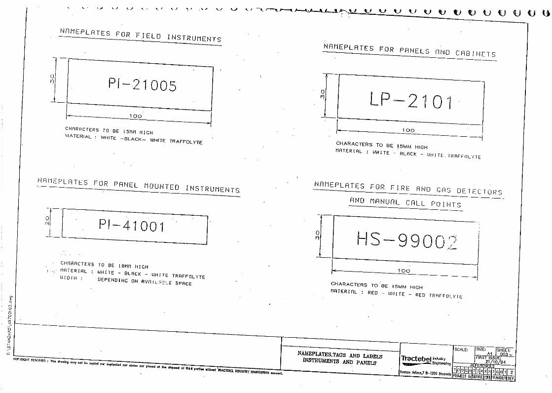

GENERAL TECHNICAL
SPECIFICATION
GTS 734 013
9 14.09.09 Logo Changed AS SD KNC
8 27.03.08 Logo Changed AS NS KNC
7 04/12/98 Changed Company name and Logo DNP PCA DNP
6 11/03/98 Updated DNP PCA DNP
5 15/09/97 Updated DNP PCA DNP
4 24/02/95 Updated DNP PCA DNP
Rev. Date Subject of revision Author Checked Approved

GENERAL TECHNICAL
SPECIFICATION
GTS 734 013
Rev. 9 – 14.09.09 Page I of V RL1 / 61 / e:\pradeep data\00_general technical specifications\gts revised 2009_gdf suez\inst 2009\soft\70000_734_gts_013__79300_859388934.doc
! "#
$
%
&
"

GENERAL TECHNICAL
SPECIFICATION
GTS 734 013
Rev. 9 – 14.09.09 Page II of V RL1 / 61 / e:\pradeep data\00_general technical specifications\gts revised 2009_gdf suez\inst 2009\soft\70000_734_gts_013__79300_859388934.doc
$
&
'
! "
$ "
%
!
!
! "
!
! ((
!
!!
$
$
$ "
$ "
$

GENERAL TECHNICAL
SPECIFICATION
GTS 734 013
Rev. 9 – 14.09.09 Page III of V RL1 / 61 / e:\pradeep data\00_general technical specifications\gts revised 2009_gdf suez\inst 2009\soft\70000_734_gts_013__79300_859388934.doc
$
$!
%
% "
% )*
% "
%
%
%!
%$ "!
& !
& !
& #!
& $
& $
& $
&! %
%
&
&
! !
&
&
&

GENERAL TECHNICAL
SPECIFICATION
GTS 734 013
Rev. 9 – 14.09.09 Page IV of V RL1 / 61 / e:\pradeep data\00_general technical specifications\gts revised 2009_gdf suez\inst 2009\soft\70000_734_gts_013__79300_859388934.doc
!
" "
"
"(
!
$
"
! +'
" !
!
"!
)*!
!

GENERAL TECHNICAL
SPECIFICATION
GTS 734 013
Rev. 9 – 14.09.09 Page V of V RL1 / 61 / e:\pradeep data\00_general technical specifications\gts revised 2009_gdf suez\inst 2009\soft\70000_734_gts_013__79300_859388934.doc
!
! $
S S S

GENERAL TECHNICAL
SPECIFICATION
GTS 734 013
Rev. 9 – 14.09.09 Page 1 of 31 RL1 / 61 / e:\pradeep data\00_general technical specifications\gts revised 2009_gdf suez\inst 2009\soft\70000_734_gts_013__79300_859388934.doc
This specification covers the basic requirements for the design, the selection, the requisitioning and the installation of instrumentation and control systems associated with equipment purchased as a "Package Unit".
,-./.0.1/2
Subject to the requirements of the context, the terms (hereafter listed in alphabetical order) used in this specification are given the following meaning
AGREEMENT Designates the agreement concluded between the CLIENT and the CONTRACTOR, under which the latter undertakes to the former the GOODS and/or SERVICES according to the stipulations which are agreed and specified in the form of an order.
CLIENT Designates the purchaser of the GOODS and/or SERVICES which are the subject of the AGREEMENT.
CONTRACTOR Designates the individual or legal entity with whom the order has been concluded by the CLIENT. The term "CONTRACTOR" may be used indifferently for a supplier, a manufacturer, an erection contractor, etc.
DAYS - WEEKS - MONTHS Specify the number of calendar days, weeks or months and not of working days, weeks or months.
ENGINEER Designates the individual or legal entity to which the CLIENT has entrusted various tasks in relation with the carrying out of his PROJECT.
GOODS and/or SERVICES Designate, depending on the case, all or part of the drawings or documents, substances, materials, materiel, equipment, structures, plant, tools, machinery,... to be studied, designed, manufactured, supplied, erected, built, assembled, adapted, arranged or put into service by the CONTRACTOR under the AGREEMENT, including all the studies, tasks, works and services specified by the order. The Terms GOODS or SERVICES may by indifferently used one for the other as required by the context.
PROJECT Designates the aggregate of GOODS and/or SERVICES to be provided by one or more CONTRACTORS.
13,204/34532/3,647,89.5,:,/02
The design, construction, materials, testing of instrumentation and control systems shall be in accordance with the codes and standards mentioned in the present specification and in other applicable General

GENERAL TECHNICAL
SPECIFICATION
GTS 734 013
Rev. 9 – 14.09.09 Page 2 of 31 RL1 / 61 / e:\pradeep data\00_general technical specifications\gts revised 2009_gdf suez\inst 2009\soft\70000_734_gts_013__79300_859388934.doc
Technical Specifications (GTS) and with the codes, standards and legal requirements listed in the Particular Technical Specifications for the PROJECT.
,;.,</3==51;47
Whenever CLIENT and/or ENGINEER review and/or approval is requested on a document to be submitted by the CONTRACTOR or before an action is implemented by the CONTRACTOR, such review and/or approval shall always be requested in writing by the CONTRACTOR to the CLIENT and/or the ENGINEER before any action subject of this review and/or approval is taken.
CLIENT and/or ENGINEER approval shall always be given in writing.
/2059:,/040.1/,5:./1716>
The terminology shall conform to ANSI/ISA S 51.1 "Process Instrumentation Terminology".
Instrument symbols and identification on P & I Diagrams shall be in accordance with the specification GTS/734/003 "Instrumentation symbols and identification".
,/,547
Instrumentation and control and monitoring systems of Package Units shall be in accordance with this specification and as defined in the P&I Diagrams.
The Package Units shall be supplied complete with all instrumentation, fully piped, wired and tested to ensure safe, reliable and effective operation as well as easy maintenance of the complete Package Units.
Protection and packing of all materials shall be suitable for shipment and protection on jobsite during storage prior to erection.
/2059:,/0,7,?0.1/
Instruments and instrumentation systems of proven reliability shall be used.
Selection of instrumentation shall be made from the approved Instrument Supplier Lists.
Any exception has to be justified and is subject to approval by the ENGINEER.
466./6
All instruments and instrumentation equipment shall be permanently identified by tags, labels and/or nameplates as defined in the drawing 7000/734/XX/7001 "Nameplates, tags and labels for instrumentation".

GENERAL TECHNICAL
SPECIFICATION
GTS 734 013
Rev. 9 – 14.09.09 Page 3 of 31 RL1 / 61 / e:\pradeep data\00_general technical specifications\gts revised 2009_gdf suez\inst 2009\soft\70000_734_gts_013__79300_859388934.doc
4./0./6
Manufacturer's standard colours shall be used for all instrumentation equipment in control and instrument rooms, unless otherwise specified.
Field instruments shall generally be epoxy painted, unless otherwise specified.
54/2:.22.1/>20,:2
1) Transmission of the process variables shall generally be by means of electronic or low level signals.
The output signal for electronic instruments shall be 4 to 20 mA DC or digital.
As far as possible, a true two-wire transmission system shall be used.
2) Local control loops shall be pneumatic.
The standard analog signal for pneumatic instruments shall be 0.2 to 1 barg.
Each pneumatic instrument shall be provided with its own air filter regulator (air set).
3) No process fluid shall be piped into the control rooms or the instrument rooms.
/?71295,24/340,5.472
All instruments shall be suitable to withstand the environmental conditions specified for the plant location.
All parts subject to moisture, fungus growth or insect attack shall be suitably treated (tropicalisation).
Local instrument housings shall be weather-proof (IP 55 minimum or equivalent) and meet the electrical area classification requirements.
All parts of instruments exposed to process fluids shall be resistant to corrosion by the corresponding fluid.
! 7,?051/.?/2059:,/040.1/./"4@4531925,42
In hazardous areas, intrinsically safe instrumentation shall be provided.
If not possible or not practical, other protection concepts (flameproof equipment, increased safety, purging, ...) may also be used where applicable.
All electrical instruments to be installed in hazardous locations shall be certified to CENELEC Standards.
Contacts shall be encapsulated and, if used in intrinsically safe circuits, contacts shall be gold plated.
$ ::9/.0>
All instruments and control systems shall be immune from the effects of any R.F. interference that may occur at the plant location in accordance with IEC 801 "Electromagnetic compatibility for industrial-process measurement and control equipment".

GENERAL TECHNICAL
SPECIFICATION
GTS 734 013
Rev. 9 – 14.09.09 Page 4 of 31 RL1 / 61 / e:\pradeep data\00_general technical specifications\gts revised 2009_gdf suez\inst 2009\soft\70000_734_gts_013__79300_859388934.doc
Equipment to be installed inside the European Community shall be in compliance with the European Community directive requirements, denoted by the "CE mark". This compliance shall extend to each relevant item.
% 7,?05.?47 1<,59==7>
The following electrical power supplies shall be used :
230 V, 50 Hz for control and monitoring system peripherals and for analysers, recorders, indicators, single loop controllers, instruments requiring a separate power supply,...
230 V, 50 Hz or 24 V DC for control cabinets and PLC cabinets,
24 V DC for transmitters, alarm and shut-down contacts, alarm systems, relay systems, switches, safety barriers,...,
24, 48 or 110 V DC for solenoid valves.
& .59==7>
The instrument air quality shall be in accordance with ISA S7.0.01 "Quality Standard for Instrument Air".
The minimum air pressure at any place in the plant shall be 4 barg.
The instrument air receivers shall have sufficient capacity for ensuring the entire instrument load during 15 minutes in case of air compressor failure.
54/2:.00,52
1) In general, transmitters shall be of the negligible displacement electronic type, except where such devices are not available or another type of device of proven superior performance is available for a specific measurement.
Pneumatic transmitters shall be equipped with an air input gauge as part of the supply air filter/regulator set.
2) Transmitter accuracy shall be ± 0.5 % of calibrated range or better. Repeatability shall be ± 0.1 % of calibrated range or better.
For metering stations, accuracy of transmitters shall be ± 0.1 % of calibrated range.
/2059:,/01//,?0.1/2
1) In general, process connections on instruments shall be 1/2" NPT. Adaptors shall not be used.
2) Pneumatic connections shall generally be 1/4" NPT. Larger sizes may be used for special applications, e.g. for high speed actuators.
3) Electrical connections on field instruments shall preferably be 20 mm ISO.
GENERAL TECHNICAL
SPECIFICATION
GTS 734 013
Rev. 9 – 14.09.09 Page 5 of 31 RL1 / 61 / e:\pradeep data\00_general technical specifications\gts revised 2009_gdf suez\inst 2009\soft\70000_734_gts_013__79300_859388934.doc
,4295./6/.02
The metric SI system shall be used for all documents. The following units of measurement as well as their multiples and sub-multiples, shall be used :
71<
gas : Nm3/h (normal : 0°C; 1.01325 bara)
liquid : m3/h (at flowing temperature) l/h for flow lower than 0.1 m3/h
steam, condensate and mass flow : kg/h.
5,2295,
gauge pressure : barg
absolute pressure : bara
vacuum : mbar vacuum
differential pressure : bar
differential pressure for flow measurements : mbar
,;,7
0 - 100 % (Process)
m (Storage Tanks)
,:=,54095,
°C
/47>2,52
direct reading (as pH, % O2, ppm, µS, etc..)
0A,5:,4295,:,/02
Current : A or mA
Voltage : V or mV
Power : kW
Force : N
Mass : kg or t

GENERAL TECHNICAL
SPECIFICATION
GTS 734 013
Rev. 9 – 14.09.09 Page 6 of 31 RL1 / 61 / e:\pradeep data\00_general technical specifications\gts revised 2009_gdf suez\inst 2009\soft\70000_734_gts_013__79300_859388934.doc
Density : kg/m3
Time : d or h or s.
?47,2/3A4502
1) Temperature instruments shall have scales calibrated in °C.
2) Pressure instruments shall have scales calibrated in barg.
3) Absolute pressure and vacuum instruments shall have scales calibrated in bara or mbar vacuum.
4) Flow instruments shall have either 0 - 10 square root (local instruments) or 0 - 100 linear scales (control room instruments).
Scale multipliers shall be based on the measurement units defined in par. 4.13.1.
5) Level instruments shall have scales calibrated 0 - 100 %.
6) Charts for all instruments shall be 0 - 100 linear.
=45,4=4?.0>
Spare capacity is depending on the type of equipment and is defined in Appendix 1.
The documents and drawings to be prepared by the CONTRACTOR are listed hereunder. Further details are given in related PROJECT specification.
1?9:,/02
As a minimum requirement, the following documents shall be provided, when applicable.
/2059:,/02?A,397,
The schedule, in .dbf or compatible files, shall list all the instruments of all the loops using their tag numbers.
The schedule shall show, among others, the type of instruments, the range, the P&I Diagram number, the location and service of the instrument, the specification number, the purchase order number, the referenced installation drawing numbers, the loop drawing number, etc..
/2059:,/034042A,,02
The data sheets shall comprise all necessary technical data associated with the instruments. They shall include, as a minimum, the tag number, process data, range, settings, materials of construction, connection sizes and ratings, manufacturer's name and model number.

GENERAL TECHNICAL
SPECIFICATION
GTS 734 013
Rev. 9 – 14.09.09 Page 7 of 31 RL1 / 61 / e:\pradeep data\00_general technical specifications\gts revised 2009_gdf suez\inst 2009\soft\70000_734_gts_013__79300_859388934.doc
47?9740.1/2A,,02
Calculation sheets for flow primary elements, control valves, safety relief valves, vacuum breakers, rupture disks, shall be provided.
=,?.-.?40.1/2-15:.?51=51?,2215B42,32>20,:2
The following documentation shall be provided by the CONTRACTOR for the Programmable Logic Controllers (PLC) and/or, if applicable, for the Process Control System (PCS) control cabinets.
1) Technical specification of the hardware structure.
2) I/O lists and arrangement in control cabinets.
3) Process specification documents (logic diagrams, sequence descriptions, description of control algorithms and interlocks, definition of mimics, instrument face plates, trending and reports).
4) Programming of PLC's with supply of commented listings of programs. Programming shall be performed in one of the following languages : Instruction List (IL), Structured Text (ST), Ladder Diagram (LD), Function Block Diagram (FBD) or Sequential Function Chart (SFC) (Grafcet). Programs shall be available on floppies.
5) Configuration for the PCS control cabinets (if applicable).
6) Hardware and software final manuals.
.201-4745:4/305.=2,00./62
That list shall show, for the concerned instrument, the tag number, the range, the P&I Diagram number, the setting of alarms and trips in process units and/or percentage.
/0,5-4?,3,2?5.=0.1/
The packaged equipment has to be inserted in the overall plant by the ENGINEER. The CONTRACTOR and the ENGINEER shall settle together the interface requirements :
utility consumption,
electrical compatibility of signals,
space required for local panel and/or equipment control panel,
junction box location on skids,
multicore cables (supplied by others) to the local panel remotely installed,
connection to other systems (type of signal, etc),
cause and effect charts interrelation,
remote control and monitoring requirements,
PCS and/or PLC interfaces (hardware and software).

GENERAL TECHNICAL
SPECIFICATION
GTS 734 013
Rev. 9 – 14.09.09 Page 8 of 31 RL1 / 61 / e:\pradeep data\00_general technical specifications\gts revised 2009_gdf suez\inst 2009\soft\70000_734_gts_013__79300_859388934.doc
Interfaces shall be defined by the ENGINEER and approved by the CONTRACTOR.
! ,50.-.?40.1/-.7,2
They shall contain copies of all electrical safety certificates and all documents applicable to the safety of electrical equipment installed in hazardous areas (e.g. intrinsically safe loop specifications).
54<./62
As a minimum requirement, the following drawings shall be prepared, when applicable.
9/?0.1/47711=354<./62
The functional loop drawings shall illustrate the process control philosophy.
16.?3.4654:2
Logic diagrams shall be prepared for all interlock and sequencing systems.
The symbols shall be in accordance with IEC 617-12.
4B7,7.202
The cable lists shall indicate details of the required cables (e.g. cable number, type, length, termination points, ...).
4B7,B71?C3.4654:2
The cable block diagrams shall show schematically an overview of the cable interconnections between panels, cabinets, racks, junction boxes and instruments.
4B7,74>190354<./62
The cable layout drawings shall show the main routing of instrument cables and the location of all instrument junction boxes and local panels.
/2059:,/074>190354<./62
The instrument layout drawings shall show the location of instruments, local panels, racks, control valves, junction boxes.
! .5./63.4654:2
The wiring diagrams shall show all cable termination details for junction boxes, crossboards, control cabinets, power supply cabinets, auxiliary cabinets, control panels, desks, etc..

GENERAL TECHNICAL
SPECIFICATION
GTS 734 013
Rev. 9 – 14.09.09 Page 9 of 31 RL1 / 61 / e:\pradeep data\00_general technical specifications\gts revised 2009_gdf suez\inst 2009\soft\70000_734_gts_013__79300_859388934.doc
$ ,74>3.4654:2
The relay diagrams shall show the connections between components of the relay system in a horizontal ladder format.
% 1<,529==7>3.4654:2
The power supply diagrams shall show, for each instrumentation power distribution board, the allocation and the rating of fuses or circuit breakers.
& 450A./6354<./62
The earthing drawings shall show the requirements of earth cabling up to the earthing systems.
11=3.4654:2
The loop diagrams shall show the connections between components of each loop with identification of terminals and cables.
4/,7?4B./,04/33,2C74>190354<./62
Those layout drawings shall show the front and rear arrangements and all the main sizes of panels, cabinets and desks. They shall include a schedule of instruments.
1/0517511:4/3./2059:,/0511:74>190354<./62
Those layout drawings shall show the location of panels, desks, cabinets, crossboards, racks, inside the control rooms and instrument rooms.
51?,22A11C(9=354<./62
The process hook-up drawings shall show installation details and tracing/insulation requirements for the various instruments, complete with a schedule of required material.
/,9:40.?4.529==7>354<./62
The pneumatic/air supply drawings shall show installation details for pneumatic loops and instrument air supply, complete with a schedule of required material.
/47>2,5A11C(9=354<./62
The analyser hook-up drawings shall show installation details and tracing/insulation requirements, complete with a schedule of required material.

GENERAL TECHNICAL
SPECIFICATION
GTS 734 013
Rev. 9 – 14.09.09 Page 10 of 31 RL1 / 61 / e:\pradeep data\00_general technical specifications\gts revised 2009_gdf suez\inst 2009\soft\70000_734_gts_013__79300_859388934.doc
.--,5,/0.47 5,2295,/2059:,/02
5.-.?,=740,2
1) Flow measurement shall normally be made using concentric square edged orifice plates with flange taps. In general, type 316 stainless steel orifice plates shall be provided.
Where the nature of the fluid is such as to require other material, it shall be suitable for the service.
If the fluid contains solids, eccentric or segmental orifice plate shall be used.
Quarter circle or conical entrance orifice plates shall be selected where Reynolds number is low.
2) The calculations, the dimensions and the installation of orifice plates, the "upstream" and "downstream" lengths, the tappings shall meet the requirements of ISO 5167.
The minimum upstream and downstream straight lengths required for installation of orifice plates are the values without parentheses ("zero additional uncertainty" values) given in Table 1 of ISO 5167.
3) Orifice plates in liquid service shall be furnished with vent holes flush with the top of the pipe and those in gas service shall be furnished with drain holes flush with the bottom of the pipe. Orifice plates for LNG service shall have a vent hole and a drain hole.
5.-.?,-74/6,24/3:,0,559/2
1) For line sizes up to and including 12", weld neck orifice flanges having flange taps and a minimum rating of 300 lb RF shall normally be used.
2) For line sizes 14" and larger, weld neck orifice flanges having flange taps and the standard line rating shall be used.
3) For accurate measurements, a holder shall be provided in order to fulfil the requirements of ISO 5167 concerning the concentricity of orifice plates.
4) Orifice plates in carrier rings, with integral corner tappings, shall be used where required by service conditions, and/or piping specifications.
5) Metering orifices shall not be installed in lines less than 2". If the line is less than 2", one of the following devices shall be used :
a) integral orifice type instrument,
b) swaged (2") meter run,
c) certified meter run with corner taps,
d) variable area flowmeter.
6) Metering orifices shall be located in horizontal lines. If not possible, the flow in vertical lines shall always be upward for liquids and downward for gases.

GENERAL TECHNICAL
SPECIFICATION
GTS 734 013
Rev. 9 – 14.09.09 Page 11 of 31 RL1 / 61 / e:\pradeep data\00_general technical specifications\gts revised 2009_gdf suez\inst 2009\soft\70000_734_gts_013__79300_859388934.doc
71</1@@7,2,/095.09B,2
1) Flow nozzles or Venturi tubes may be used for measurement of slurries or suspended solids, or when low pressure loss is required in high velocity streams.
2) The requirements of ISO 5167 shall be applied for calculations, dimensions, "upstream" and "downstream" lengths, tappings.
The minimum upstream and downstream straight lengths required for installation of nozzles and Venturis are the values without parentheses ("zero additional uncertainty" values) given in Tables 1 and 2 of ISO 5167.
.01009B,2
Averaging Pitot tubes may be used for non-critical flow metering in large pipes and for applications where a low pressure loss is required.
/0,654715.-.?,0>=,./2059:,/02
For low flow rates in lines less than 2" diameter, integral orifice type instruments may be used.
,0,554/6,
1) The meter differential range shall be selected so that the d/D (Beta) ratio falls between 0.25 and 0.75. For custody transfer flow measurement, the d/D ratio shall be ≤ 0.6.
The standard differential range shall be 250 mbar.
If required, other differential ranges may be used (50 mbar, 125 mbar, 500 mbar).
For compressible fluids, the differential range in mbar, divided by the upstream pressure measured in bar absolute, shall not exceed 36.
2) The meter range shall be selected so that
the normal flow rate falls between 70 % and 80 % of the meter range;
the minimum and maximum flow rates fall between 30 % and 95 % of the meter range.
! .--,5,/0.47=5,2295,:,4295./63,;.?,2
The differential pressure produced by the primary flow element shall be measured by a differential pressure transmitter (differential capacitance type, inductance variation type or similar).
Transmitter process connections shall be 1/2" NPT.
For local measurement , bellows type displacement instrument may be used.

GENERAL TECHNICAL
SPECIFICATION
GTS 734 013
Rev. 9 – 14.09.09 Page 12 of 31 RL1 / 61 / e:\pradeep data\00_general technical specifications\gts revised 2009_gdf suez\inst 2009\soft\70000_734_gts_013__79300_859388934.doc
45.4B7,5,471<:,0,52
1) Variable area flowmeters shall generally be used when wide rangeability (10 to 1), linear output or the measurement of very low flow rates is required.
2) Variable area flowmeters shall generally be used in pipes sizes 2" or smaller.
3) Variable area flowmeters are available as indicators, transmitters or a combination of the above, with or without alarms.
4) Variable area flowmeters range shall be selected so that normal flow falls between 50 and 60 % of the maximum scale.
5) Fluids containing solids shall be adequately filtered before entering the instrument interior.
6) Unless otherwise stated, material and rating shall be in accordance with the piping class.
7) Metal tube meters shall be used for process application or in hazardous service.
Glass tube meters shall only be used on low pressure service for small flows of liquid or gas for the measurement of purges to instrument tappings or analyser sample flows.
7,?051:46/,0.?71<:,0,52
Electromagnetic flowmeters are used for flow measurement of liquids having some degree of electrical conductivity.
They are mainly suitable for measurement of slurries, corrosive fluids or dirty fluids.
Vertical mounting is preferred.
95B./,,0,52
Turbine meters are used for accurate measurements and wide rangeability.
They are commonly used in custody transfer of light products or crude oils.
12.0.;,.2=74?,:,/0,0,52
Positive displacement meters are used when high accuracy over a wide flow range is required. They shall be installed in horizontal lines with an adequate upstream strainer.
They are commonly used in custody transfer, especially for heavy or viscous fluids.
150,D71<:,0,52
Vortex flowmeters are used in steam, liquid and gas services where large turn-down is required.
! 0A,571<:,0,52
Depending upon the application, the following flowmeters may be considered :
GENERAL TECHNICAL
SPECIFICATION
GTS 734 013
Rev. 9 – 14.09.09 Page 13 of 31 RL1 / 61 / e:\pradeep data\00_general technical specifications\gts revised 2009_gdf suez\inst 2009\soft\70000_734_gts_013__79300_859388934.doc
target flowmeters,
ultrasonic flowmeters,
mass flowmeters (for mass flow and accurate measurement).
$ 71<<.0?A,2
Field mounted flow switches are only used for detection of a flow limit when no other flow measurement exists. Thermal type is preferred.
Variable area flowmeters with contact may be used as flow switches.
% /2047740.1/
Except for differential pressure elements, the different flowmeters here above listed shall be installed according to the manufacturer's recommendations.
! 54/2:.00,52
The pressure and differential pressure transmitters shall be of the capacitance type, piezoresistive type or similar.
If required by service conditions, other types may be used.
Transmitter process connections shall be 1/2" NPT.
! 5,2295,496,2
Pressure gauges (mostly Bourdon tube type) shall have 100 mm dial, stainless steel pressure element and stainless steel case with blow-out disc.
Differential pressure gauges shall be of the bellows or diaphragm type.
Pressure gauge process connection shall be 1/2" NPTM.
Pneumatic receiver gauges may have a 1/4" NPTM connection.
! 5,2295,<.0?A,2
Pressure switches shall be snap acting type with dry SPDT contact. Switch differential shall be adjustable.
Internal setting adjustment shall be provided.
Process connection for pressure switches shall be 1/2" NPT.
Where pressure switches are not suitable, switching will be achieved by a trip amplifier using an analog signal.

GENERAL TECHNICAL
SPECIFICATION
GTS 734 013
Rev. 9 – 14.09.09 Page 14 of 31 RL1 / 61 / e:\pradeep data\00_general technical specifications\gts revised 2009_gdf suez\inst 2009\soft\70000_734_gts_013__79300_859388934.doc
! 5,2295,4/6,2
1) Range shall be selected so that normal pressure be in the middle third of the span, if possible.
2) Suppressed ranges may be used to obtain better sensitivity where required.
! ;,5(4/6,/3/3,5(4/6, 510,?0.1/
1) Instruments shall have over-range protection to the maximum pressure to which they may be exposed.
2) Instruments exposed to vacuum shall have under-range protection to full vacuum.
! .2?,774/,192
1) Diaphragm seals shall be used for pressure instruments on slurries, viscous or highly corrosive fluids.
2) For all pressure instruments and gauges on the suction and discharge of reciprocating pumps or compressors, liquid-filled gauges or close coupled pulsation dampeners shall be used.
!! /2047740.1/
Due consideration is to be given to the installation of all pressure and differential pressure measuring devices to eliminate errors due to static head, condensation, gas, etc...
$ .--,5,/0.47 5,2295,,;,754/2:.00,52
Wherever possible differential pressure transmitters (differential capacitance type, inductance variation type or similar) shall be used for level measurements.
The transmitters shall be provided with elevation/suppression kit.
Transmitter process connections shall be 1/2" NPT.
$ .2=74?,5>=,,;,754/2:.00,52
External displacer type level transmitters shall be used for liquid/liquid interface measurement. They may also be used for narrow measuring ranges up to 1524 mm. They shall be fitted with 2" flanges.
Internal displacer type level transmitters shall normally be supplied for open tanks and sump. They shall be fitted with a 4" flange.
$ 0A,5>=,2
Depending on the application, other level instrument types (internal displacement or ball float type, capacitance type, conductivity type, radioactive type, ultrasonic type, ...) may be used.

GENERAL TECHNICAL
SPECIFICATION
GTS 734 013
Rev. 9 – 14.09.09 Page 15 of 31 RL1 / 61 / e:\pradeep data\00_general technical specifications\gts revised 2009_gdf suez\inst 2009\soft\70000_734_gts_013__79300_859388934.doc
$ ,;,7<.0?A,2
Displacer or float type level switches are used for alarming or shut-down.
The external displacer or float type shall be fitted with 2" flanges and the internal displacer or float type with 4" flanges.
Vibrating fork type, ultrasonic type, capacitance type or conductivity type level switches may be used for specific applications.
$ ,;,7496,2
1) Magnetic type level gauges are preferred on hydrocarbons and organics and shall be used where application does not allow glass.
2) Gauge glasses shall be reflex type except for interface service and for liquids which may coat the inner surface of the reflex glass.
In the latter cases, transparent gauge glasses shall be used.
The gauge glasses shall be provided with gauge cocks.
3) The visible length of a level gauge must overlap the range of any associated level transmitter or controller.
4) Process connections shall be 1" flanged.
$ 4/C496,2
Storage tank level measurement shall normally be performed by float and tape type instruments (servo-gauges). For some applications, radar systems shall be considered.
For local tank level indication, a float type level indicator may be used.
$! 0.77./6,772
Stilling wells shall be provided inside vessels and tanks for internal displacer instruments and float type instruments.
The design shall include a retaining device to prevent loss of displacer or float.
The wells shall have vertically overlapping slots throughout their length.
% ,/,547
1) Temperature elements shall generally be installed in thermowells and be removable during plant operation.

GENERAL TECHNICAL
SPECIFICATION
GTS 734 013
Rev. 9 – 14.09.09 Page 16 of 31 RL1 / 61 / e:\pradeep data\00_general technical specifications\gts revised 2009_gdf suez\inst 2009\soft\70000_734_gts_013__79300_859388934.doc
2) The design of thermowells, temperature transmitters and temperature elements shall be in accordance with the ENGINEER specification.
% A,5:1<,772
1) Screwed thermowells (3/4" NPT) shall generally be used. They shall be drilled and machined from stainless steel bar stock.
They shall be foreseen for all temperature measurements except for thermocouples in concrete and for skin sensors.
Flanged thermowells shall be used when piping or vessel specification requires flanged connections.
2) Thermowell immersion shall be at least half of the nominal ID of the line up to and including 12" line size. In lines above 12", the thermowell immersion shall be 6" minimum.
For temperature measurements in vessels and tanks, the immersion length shall be 10" minimum.
3) Thermowells shall be provided with an extension when used on insulated pipes and vessels.
% ,2.204/?,,:=,54095,,0,?0152)*
Pt100 Resistance Temperature Detectors shall be used for remote temperature measurements.
They shall be specified for temperature from minus 200°C to plus 500°C.
RTD shall be 3-wire type and conform to IEC 751 grade 1.
% A,5:1?19=7,2
Thermocouples shall be used for temperature measurements above 500°C. They shall generally be NiCr-Ni (type K). Depending on the application, other types may be used.
The thermocouples shall conform to IEC 584.
% C./,/2152
Skin sensors shall be used for wall temperature measurement on tanks, vessels and pipes.
% ,:=,54095,54/2:.00,52
Temperature measuring elements (RTD or thermocouples) used in control loops shall be supplied with an industrial head housing including a two-wire transmitter.
%! 1?47,:=,54095,496,2
Temperature gauges shall be used for local indication and shall be bimetallic every angle type or filled system type. They shall be stainless steel and shall have 100 mm dial. They shall be fitted with a 1/2" NPT adjustable union for connection to well.
GENERAL TECHNICAL
SPECIFICATION
GTS 734 013
Rev. 9 – 14.09.09 Page 17 of 31 RL1 / 61 / e:\pradeep data\00_general technical specifications\gts revised 2009_gdf suez\inst 2009\soft\70000_734_gts_013__79300_859388934.doc
All capillary tubing shall be stainless steel armored.
%$ ,:=,54095,<.0?A,2
Temperature switches shall only be used for alarming or shut-down when no other temperature measurement exists.
They shall be snap acting type with dry SPDT contact.
Switch differential shall be adjustable.
Internal setting adjustment shall be provided.
& 47;,,7,?0.1/
1) For general service, single seated globe type control valves (with heavy top, top and bottom, or cage guiding), shall normally be used. Double seated globe valves with top and bottom guiding or rotary shaft (eccentric rotary plug) type valves, may be used where required by process operating conditions.
2) Diaphragm, plug, butterfly, ball, or angle valves shall be used where required by line piping specifications.
Typically, butterfly valves shall be used for large volume flows at low shut-off differential pressures, and ball valves for large volume flows at high shut-off differential pressures. Angle valves shall be used to avoid solids accumulation and on erosive and flashing services. Diaphragm valves shall be applied for slurry service.
3) Self acting valves may be used for local control of utilities.
4) Control valve location, type, size and trim shall be carefully selected in order to avoid cavitation.
& 47;,40,5.472
The materials selected for the valve components shall be conform to the process requirements and shall be specified in the data sheets.
Steel valve bodies shall be forged (from 1 1/2" and below) or cast (from 2" and above).
Valves manufactured from rolled plates or from assembly by welding of cast parts are prohibited.
Asbestos and/or asbestos compound are not acceptable for packing. Teflon ring type packing shall be used up to 230°C.
& 47;,.@./6
Sizing of control valves shall be performed by using the flow equations given in ANSI/ISA - S 75.01 or by using the method recommended by the valve Manufacturer. The Cv of the valve shall be calculated on basis of 1.3 times the operating flow or of 1.1 times the maximum flow (the highest value is chosen).

GENERAL TECHNICAL
SPECIFICATION
GTS 734 013
Rev. 9 – 14.09.09 Page 18 of 31 RL1 / 61 / e:\pradeep data\00_general technical specifications\gts revised 2009_gdf suez\inst 2009\soft\70000_734_gts_013__79300_859388934.doc
The calculated Cv value shall be corrected taking into account pipe reductions, cavitation and/or critical velocity.
& 1.2,
The noise level of control valves shall not exceed 80 dBa, as measured 1 meter downstream of the valve within 1 m radially from the pipe outside diameter.
& ?0940152
1) Wherever possible, valves shall be operated by spring return pneumatically operated diaphragm actuators.
2) Spring return piston actuators shall be used to provide longer strokes or greater thrust than is available from spring diaphragm units. They shall normally be sized to operate at an air supply of 4.0 barg.
3) Double-acting piston actuators which do not automatically fail to a safe position in the event of air failure shall be supplied with local air receiver, having sufficient capacity for at least three operations over the full travel of the valve. The use of such actuators shall not jeopardise plant safety.
4) Valve action on control signal or air failure shall be as indicated on P&ID. Shut-down valves shall move to a safe position on actuator power failure or on electrical signal failure.
5) Motor operated valve actuators shall have integral reversing starters and interposing relays.
The actuator shall be fitted with a torque switch, thermostat and space heater.
The actuator shall have position limit switches (open/closed) for stopping the motor at limit of travel.
6) Valve actuators shall be suitable for operating the valve with a differential pressure equivalent to the full upstream pressure.
& ??,2215.,2
& 12.0.1/,52
The control valves shall be fitted with electro-pneumatic positioners.
The positioners shall be provided with :
integrally mounted pressure gauge for air supply and positioner output air pressure,
air/filter regulators integrally mounted and piped by the manufacturer.
& .:.02<.0?A,2
Limit switches shall be of the inductive proximity type.
They shall be external to the actuator, not an integral part of it.
Exceptions have to be approved by the ENGINEER.

GENERAL TECHNICAL
SPECIFICATION
GTS 734 013
Rev. 9 – 14.09.09 Page 19 of 31 RL1 / 61 / e:\pradeep data\00_general technical specifications\gts revised 2009_gdf suez\inst 2009\soft\70000_734_gts_013__79300_859388934.doc
& 17,/1.3;47;,2
Solenoid valves shall be suitable for the specified DC supply.
& 1120,55,74>2
Booster relays shall be fitted where necessary to ensure speed of response of valves and shall be close coupled to the valve actuator.
& 1?C(9=5,74>2
Lock-up relays may be used where process conditions demand and where they cannot give rise to a hazardous situation.
& /,9:40.?09B./6
Stainless steel 1/4" or 3/8" OD tubing shall be used for pneumatic connection between the positioner and the valve actuator.
Fittings shall be stainless steel compression type (two-ferrule type).
&! 1//,?0.1/2
1) Control valves shall have flanged connections. The flange rating and facing shall be in accordance with piping class. The face-to-face dimensions shall comply with ANSI/ISA S 75.03.
2) Except for cryogenic and gas applications, butterfly valves shall be of the wafer type designed to fit between piping flanges. Face-to-face dimensions shall be in accordance with ANSI/ISA S 75.04, where possible.
3) Connections for on-off valves shall be in accordance with piping class.
4) Pressure regulators may be of flanged type or of screwed type. Screwed type is subject to ENGINEER approval.
4-,0>,7.,-47;,2
1) Safety relief valves may be either of the conventional or balanced type. For specific applications, pilot operated relief valves may be considered.
For steam and high temperature service, open spring safety valves may be required.
2) Lifting levers shall be used on safety valves in steam generation service, on safety valves for air receivers and on other safety valves when required by codes or when specified.
Test gags shall not be provided.
3) Orifice area calculation shall be made in accordance with ASME VIII and API RP 520.

GENERAL TECHNICAL
SPECIFICATION
GTS 734 013
Rev. 9 – 14.09.09 Page 20 of 31 RL1 / 61 / e:\pradeep data\00_general technical specifications\gts revised 2009_gdf suez\inst 2009\soft\70000_734_gts_013__79300_859388934.doc
4?99:5,4C,52
1) Vacuum breakers shall be of the diaphragm type pallet seating design.
2) Pallets shall have drip rings to eliminate condensate collecting at seats.
9=095,.2?2
Rupture discs may be used, alone or in conjunction with a safety valve, as protective devices against over-pressure or vacuum.
! !
/47>2,52
1) The analysers shall be furnished, when required, with pre-assembled sampling system and calibration system.
2) Analyser selection shall be made according to the following criteria :
principle of operation for use in the application,
type of output signals for data transmission,
serviceability,
reliability,
ease of installation,
utilities required,
simplicity of design.
4:=7./6/347.B540.1/>20,:2
1) Sampling systems shall comprise all necessary equipment to extract from the process a sample that truly represents the process fluid characteristics, to deliver it to the analyser at the required temperature, pressure and flow rate, to dispose of spent sample and wastes, and to provide a means of calibrating the entire system.
2) Means shall be provided for checking the calibration of the analyser.
3) Analyser sampling and calibration systems shall be in accordance with API 555, "Process Analyzers".
/47>2,5>20,:/2047740.1/
Suitable protection shall be provided for ensuring reliable, accurate and safe operation of the analyser systems.
When the analyser case is not sufficient to provide the required protection, a housing is required.

GENERAL TECHNICAL
SPECIFICATION
GTS 734 013
Rev. 9 – 14.09.09 Page 21 of 31 RL1 / 61 / e:\pradeep data\00_general technical specifications\gts revised 2009_gdf suez\inst 2009\soft\70000_734_gts_013__79300_859388934.doc
The type of housing (cabinet, shelter, house) will depend on the analyser, the environment in which it will operate, the sample line length, the ease of maintenance and the economics.
!
=,540.1/471/0517 A.7121=A>
The main control and monitoring functions will be carried out by a Process Control System (PCS) which will act as the operator interface for the whole plant.
The tasks covered by the PCS will be related to continuous loops, on/off devices control, sequencing control, recipe handling, …, and to operator interface requirements like real time and historical trending, alarming functions, interactive mimics, ...
1/0517/31/.015./6>20,:215A, 4?C46,/.02
1) The monitoring and remote operation of the Package Units shall be carried out from the main control room by means of the PCS in three possible ways.
Type 1 : All safety functions, sequences, control functions are achieved by the PCS and/or the Emergency Shut-Down (ESD) system foreseen by the ENGINEER;
Type 2 : All safety functions, sequences, control functions are achieved by systems provided by the CONTRACTOR.
Supervisory functions and remote controls (start-stop) are achieved by the PCS if required;
Type 3 : Safety functions and sequences are achieved by systems provided by the CONTRACTOR.
Control functions, supervisory functions and remote controls are achieved by the PCS.
The type of control and monitoring system is defined in the Particular Technical Specification for the PROJECT.
The CONTRACTOR shall be responsible for :
the complete engineering and detailed design for the Package Unit instrumentation, control cabinets and local control panel (if required); interface terminal blocks shall be submitted to the approval of the ENGINEER,
the connections to the skid mounted junction boxes and to the Package Unit control cabinets or local control panels if mounted in the vicinity of the equipment,
the detailed design of cables and wiring from instrumentation or skid junction boxes to Package Unit cabinets or Package Unit control panels mounted remotely or in instrument rooms.
2) If applicable, the CONTRACTOR shall supply a programmable controller (PLC) in order to perform the functional sequences, controls, interlocks, safeguardings (non critical shut-downs) associated with the Package Unit.

GENERAL TECHNICAL
SPECIFICATION
GTS 734 013
Rev. 9 – 14.09.09 Page 22 of 31 RL1 / 61 / e:\pradeep data\00_general technical specifications\gts revised 2009_gdf suez\inst 2009\soft\70000_734_gts_013__79300_859388934.doc
The PLC will be interfaced to the PCS by serial link, or in case of a small number of exchanged information by discrete I/O's.
The serial link type and the communication protocol shall be as agreed between the CONTRACTOR, the ENGINEER and the PCS manufacturer.
3) When specifically required, the CONTRACTOR shall provide, as an alternative to PLC, a PCS control cabinet which shall be integrated in the overall plant control system.
4) Local panels shall be provided, if necessary, for the minimum local operation and monitoring of the equipment requested by the CONTRACTOR. Those panels shall contain push buttons, switches, lamps, indicators, annunciator lamp boxes and pneumatic instruments (if any).
1?47745:2/3A90(1</1/3.0.1/2
1) Visible annunciator systems shall generally be of the solid state back-lighted nameplate type. The system shall be provided with common "acknowledge" and "test" push buttons. Twin lamps shall be provided for each window.
The alarm sequence shall be in accordance with ISA S18.1. It shall include a first-out feature of sequence number F3-A-3 when applicable.
2) Contact initiating alarms or shut-down shall be closed in normal operation and shall open in case of fault conditions.
The shut-down actuators (solenoid valves, relays, ...) shall be energised under normal operation and de-energised for shut-down.
3) The shut-down functions shall be carried out by the PLC associated with the Package Unit, but emergency shut-down conditions shall be implemented using safety relay logic and/or safety PLC.
??,22.B.7.0>
1) The installation of instrumentation shall be such as to minimise the effects of fire, solar radiation, vibration, heat from process equipment, condensation, spillage, rain, and maintenance activities, etc.
2) Instruments and their connections shall always be accessible from ground level, floors, platforms, walkways (2 m above or 1 m either side of).
/2059:,/01//,?0.1/2/ .=./6/3,22,72
Instrument connections on piping and vessels shall be as indicated in Appendix 2.
Connections for items such as analysers, and those required in ducts, heater stacks, etc., shall be determined to suit each type of application.
The location of flow and pressure instruments connections on horizontal pipes shall preferably be as indicated in Appendix 3.

GENERAL TECHNICAL
SPECIFICATION
GTS 734 013
Rev. 9 – 14.09.09 Page 23 of 31 RL1 / 61 / e:\pradeep data\00_general technical specifications\gts revised 2009_gdf suez\inst 2009\soft\70000_734_gts_013__79300_859388934.doc
/2059:,/0 51?,22 .=./6
1) The instrument impulse lines shall include facilities for isolation, maintenance, protection, testing and calibration.
2) The primary isolating valves shall meet the piping specification requirements.
The requirements for double block valves shall apply to primary piping or vessel connection only.
3) Vent and drain facilities, as required for maintenance and/or test and calibration, shall be fitted with valves.
4) The instrument impulse lines shall be designed to compensate the expansion or contraction of the process pipes due to temperature variations.
5) Flow and pressure transmitters and pressure switches in gas service shall be mounted above the tapping points.
In liquid and steam service, they shall be mounted under the tapping points.
In cryogenic service, all flow and pressure transmitters and pressure switches shall be mounted above the tapping points and the level transmitters above the top tapping point.
/2059:,/0.59==7>
1) Air supply headers and sub-headers shall be sized as follows :
Number of consumers Nominal pipe size
4 1/2"
10 3/4"
25 1"
80 1 1/2"
150 2"
300 3" 2) Main line take-offs for sub-headers shall be from the top of the line and shall be fitted with isolating.
Drain valves shall be provided at each low point on the sub-headers.
3) Each pneumatic instrument shall have its individual air supply line equipped with an isolating valve and an air filter or an air filter-regulator.
5,?0.1/15C2
The installation, calibration, checking and testing of instrumentation shall be performed by the CONTRACTOR, except otherwise specified.
If the erection works are performed by others, the CONTRACTOR shall provide supervision and remains responsible for the erection works until completion.

GENERAL TECHNICAL
SPECIFICATION
GTS 734 013
Rev. 9 – 14.09.09 Page 24 of 31 RL1 / 61 / e:\pradeep data\00_general technical specifications\gts revised 2009_gdf suez\inst 2009\soft\70000_734_gts_013__79300_859388934.doc
/2047740.1/40,5.47
/2059:,/0=51?,22=.=./6
316 stainless steel tubing, compression fittings, manifolds and valves shall be used for instrument process piping connected to the isolating valves on process lines and equipment, unless process conditions require another material.
/2059:,/04.5=.=./64/309B./6
a) Galvanised carbon steel pipes, fittings and valves shall be used for the main air distribution.
b) For pneumatic signals and individual air supply lines, copper tubing PVC covered and brass compression fittings and valves shall be used.
If required by environmental conditions, 316 stainless steel tubing and fittings will be used.
0A,5./2047740.1/:40,5.47
The other instrumentation installation material (junction boxes, marshalling cabinets, auxiliary cabinets, power distribution cabinets, cable glands, push-buttons and lamps, protective housings, supports, cable trays and ladders, cable conduits, etc…) shall comply with the ENGINEER specifications.
!
The supports for instruments and junction boxes shall be in accordance with the standard drawing 70000/734/XX/7002 "Standard supports for instrumentation".
$ /2059:,/0 510,?0.1/
Weather protection and, when applicable, mechanical protection shall be provided.
The method of protection shall be carefully selected in function of the fluid properties, toxicity and hazard.
Fragile instruments shall be supported independently of equipment which may generate nuisances (e.g. possible damage by mechanical vibrations).
,/,547
1) All field mounted electrical and electronic instruments shall be connected by means of individual cables to field mounted junction boxes.
2) The field mounted junction boxes shall be provided for the connection of multicore cables and of individual cables to local instruments.
Different types of signals shall be segregated into separate junction boxes :

GENERAL TECHNICAL
SPECIFICATION
GTS 734 013
Rev. 9 – 14.09.09 Page 25 of 31 RL1 / 61 / e:\pradeep data\00_general technical specifications\gts revised 2009_gdf suez\inst 2009\soft\70000_734_gts_013__79300_859388934.doc
analogue signals,
RTD signals,
thermocouple signals,
frequency signals,
logic signals,
solenoid valves,
power supply.
A further segregation shall be made between intrinsically safe and non-intrinsically safe signals.
3) Multicore cables shall be used between each field mounted instrument junction box or panel and the marshalling terminations in the instrument rooms or in the control rooms.
4) All field cable runs shall be designed to prevent ingress of moisture. Side or bottom entries to instruments or junction boxes should be used to ensure this. Cables shall have drip loops.
5) Spare capacity to be provided in multicore cables is defined in Appendix 1. This spare capacity is applicable to the as built situation.
6) The cables shall be installed above ground on cable trays and/or ladders made of heavy duty galvanised steel. Cable runs shall be designed to avoid all possible fire hazards. Where this is not practical, cable runs shall be fireproofed using metal trunking, mineral wool and galvanised cladding.
7) The numbering system for cables, junction boxes, crossboards, panels, cabinets, consoles, shall be specified by the ENGINEER.
8) All cables and wires shall be numbered. All cables shall be marked at each end. Each wire shall be labelled (terminal strip reference).
9) Where field cables are run in areas with little available means of support (e.g. structural steelwork), cables shall be laid in trenches.
10) All cables shall pass through a compression type cable gland before being terminated.
Glands shall meet the requirements of the area in which they are installed and certification shall be required where applicable.
4B7,2
The instrumentation cables shall be selected in function of the application on basis of the ENGINEER specification.
,5:./40.1/2
1) Screw clamp type terminals shall be used. Conductor ends shall be fitted with crimped end-sleeves.
Only one wire shall be connected to each terminal side.

GENERAL TECHNICAL
SPECIFICATION
GTS 734 013
Rev. 9 – 14.09.09 Page 26 of 31 RL1 / 61 / e:\pradeep data\00_general technical specifications\gts revised 2009_gdf suez\inst 2009\soft\70000_734_gts_013__79300_859388934.doc
Terminal straps shall be used for bridges between terminals.
2) Sufficient slack cable shall be left neatly coiled or looped at terminals to allow for the re-making of terminations, additions and testing.
3) Attention shall be given to the location of terminal rails in junction boxes, etc.., in order to provide sufficient space to install field cables without bunching or congestion. All cable and terminal numbers shall be clearly visible.
4) All spare wires of instrument cables shall be terminated to terminals in junction boxes, local panels, cabinets, control room panels, etc..
,65,640.1/-4B7,2
Instrumentation cables (4-20 mA, mV signals, etc.) shall be adequately separated from power wiring and electrical equipment to minimize interferences. The physical distance between instrumentation cables and power cables in parallel routing shall be as follows :
Voltage (V) Min. distance (mm)
110 400
230 400
400 600
690 600
6000 1200 If required, the instrumentation cables shall cross the power cables at right angle and with a minimum distance of 300 mm.
450A./6
Earthing of instruments, panels, consoles, shall be carried out in accordance with the applicable code requirements.
?5,,/./6
Screens on instrument cables carrying 4-20 mA and on-off signals (low level, low impedance signals) shall be interconnected and earthed at one point (preferably in the instrument room).
Exception shall be done for cables carrying digital (serial) signals, high frequencies, etc. In those case, the screens shall be earthed at both ends to prevent against electromagnetic interferences caused by HF radiations.
! +9/?0.1/1D,2
Junction boxes shall be of approved design with components to meet the requirements of the area classification.

GENERAL TECHNICAL
SPECIFICATION
GTS 734 013
Rev. 9 – 14.09.09 Page 27 of 31 RL1 / 61 / e:\pradeep data\00_general technical specifications\gts revised 2009_gdf suez\inst 2009\soft\70000_734_gts_013__79300_859388934.doc
In this specification reference is made to the following documents.
"
734/003 Instrumentation symbols and identification.
70000/734/XX/7001 Nameplates, tags and labels for instrumentation.
70000/734/XX/7002 Standard supports for instrumentation.
"
IEC 584 : Thermocouples
IEC 617-12 : Graphical symbols for diagrams - Binary logic diagrams.
IEC 751 : Industrial platinum resistance thermometers sensors.
IEC 801 : Electromagnetic compatibility for industrial - process measurement and control equipment.
)*
ISO 5167 : Measurement of fluid flow by means of pressure differential devices
Part 1 : Orifice plates, nozzles and Venturi tubes inserted in circular cross section conduits running full
Part 2 : Diaphragms or nozzles installed at the inlet of a conduit.
API RP 520 : Sizing, Selection, and Installation of Pressure-Relieving Devices in Refineries.
API 555 : Process Analyzers.
ANSI/ISA S7.0.01 : Quality standard for instrument air.
ANSI/ISA S18.1 : Annunciator sequences and specifications.
ANSI/ISA S51.1 : Process Instrumentation terminology.
ANSI/ISA S75.01 : Flow equations for sizing control valves.

GENERAL TECHNICAL
SPECIFICATION
GTS 734 013
Rev. 9 – 14.09.09 Page 28 of 31 RL1 / 61 / e:\pradeep data\00_general technical specifications\gts revised 2009_gdf suez\inst 2009\soft\70000_734_gts_013__79300_859388934.doc
ANSI/ISA S75.03 : Face-to-face dimensions for flanged globe style control valve bodies (ANSI classes 125, 150, 250, 300 and 600).
ANSI/ISA S75.04 : Face-to-face dimensions for flangeless control valve bodies (ANSI classes 150, 300 and 600).
!
ASME section VIII : Boiler and pressure vessel code - Pressure vessels.
S S S

GENERAL TECHNICAL
SPECIFICATION
GTS 734 013
Rev. 9 – 14.09.09 Page 29 of 31 RL1 / 61 / e:\pradeep data\00_general technical specifications\gts revised 2009_gdf suez\inst 2009\soft\70000_734_gts_013__79300_859388934.doc
APPENDIX 1 TO THE SPECIFICATION GTS/734/013 - SPARE CAPACITY
Spare capacity is depending on the type of equipment and is defined in the following table.
ITEM DESCRIPTION SPARE
1 PLC and PCS I/O cabinets
installed spare components 5 %
spare space for future extensions
(with prewired connections)
10 %
2 Multicore cables
spare cores (all cores have to be connected to the terminals of junction boxes, marshalling racks or any other terminal strip)
20 %
3 Cable ladders and trays
spare room for additional cables
30 %
4 Alarm systems
installed spare electronic cards 5 %
spare slots for additional electronic cards with prewired connections
20 %
non-engraved spare annunciator windows with prewired connections
20 %
5 Marshalling racks
spare poles for additional cables 20 %
spare room for additional crossboard terminals or modules
10 %
6 Power distribution cabinets
spare miniature circuit breakers connected to the power supply
10 %
spare room for additional miniature circuit breakers
10 %

GENERAL TECHNICAL
SPECIFICATION
GTS 734 013
Rev. 9 – 14.09.09 Page 30 of 31 RL1 / 61 / e:\pradeep data\00_general technical specifications\gts revised 2009_gdf suez\inst 2009\soft\70000_734_gts_013__79300_859388934.doc
APPENDIX 2 TO THE SPECIFICATION GTS/734/013 - INSTRUMENT CONNECTIONS
Type of instrumentation Connections Notes
Piping Vessel or equipment
Temperature 3/4" threaded 3/4" threaded
2" flanged 2 flanged (1) (2)
Pressure 1/2" threaded 1/2" threaded
3/4" flanged 3/4" flanged (1) (2)
2" flanged 2" flanged (2) (3)
F
L
Orifice flanges, Venturis, nozzles, 1/2" threaded (NPT) -
O
W
Averaging Pitot tubes as per manufacturer recommendation -
Differential pressure 1/2" threaded
type transmitter 3/4" flanged (2) (4)
L Diagram type transmitter 3" or 4" flanged (2) (5)
E External displacer type 2" flanged (2)
Internal displacer type 4" flanged (2)
V Level switch external float 2" flanged (2)
E
Level switch internal float 4" flanged (2)
L Level switch, ultrasonic, capacitance, conductivity, …
2" flanged (2)
Level gauge 1" flanged (2)
2" flanged (2) (4)
Notes
(1) For plastic or lined vessels and piping,
(2) Rating and facing as per piping or vessel specification,
(3) For instruments with diaphragm seal,
(4) For plastic or lined vessels,
(5) 3" for flush diaphragm type and 4" for extended diaphragm type.

GENERAL TECHNICAL
SPECIFICATION
GTS 734 013
Rev. 9 – 14.09.09 Page 31 of 31 RL1 / 61 / e:\pradeep data\00_general technical specifications\gts revised 2009_gdf suez\inst 2009\soft\70000_734_gts_013__79300_859388934.doc
APPENDIX 3 TO THE SPECIFICATION GTS/734/013 - LOCATION OF FLOW AND PRESSURE
INSTRUMENT CONNECTIONS
ON HORIZONTAL PIPES
Fluid Location of instrument connections Notes
Gas Vertically upward (2)
Steam Horizontally
Liquid From horizontal centre line down to 45° below horizontal centre line
(1) (2)
Notes
(1) For slurry and corrosion service, connections must be on top of piping.
(2) For cryogenic gas and liquid, see Piping Standard Assemblies.
S S S

QAP No
Date
Prepared by MA
Approved by
Project
Client
Consultant
MContractor's
TPI
General Finish Job Card
Verification of
- Modal No.
- Serial No.
- Calibration Range
- Material of construction
- Customer Tag P R/W
- Certification Lable
- Process connection
- Asscessories
- Calibration Critical ElectricalCalibration Procedure
& Job Card
Calibration
Procedure & Job
Card
- Calibration / Accuracy / Range
- Load Variation Test
- Power Supply Variation Test
- Reverse Plolarity Test
- Accessories Major Visual As per Model As per Model
- Communication with HART
Communicator
- Verfication of Model & Tag No.
- Over range Pressure Test Critical Visual 100% Product Data SheetProduct Data
Sheet
M P Perform
C W/R Witness
TPI W/R Witness of Test / Review of Certificates & Documents as per QAP
Witness Test / Inspection
Procedure & Job CardProcedure & Job
CardComliance Report
2
Critical Electrical
Critical
SKH
BUPL
GAIL
W
P W
Calibration Procedure
& Job Card
100%
Remarks
100%Electrical
Visual
Type of Check
PTest & Calibration
Report
Acceptance
norm
Inspection By
Format Of
Records
Third Party Inspection Agency
Manufacturer
Consultant /Owner
P.011947-Q-11000-102 Rev.0
01.05.18
TE-IN
Checked : SHD
INTERNAL TEST / INSPECTION1
Job Card & Product
Data SheetMajor
Calibration
Procedure & Job
Card
Legend
100%
QUALITY ASSURANCE PLAN
PRESSURE & TEMPERATURE TRANSMITTER
Sr.
NoDescription Characteristic Class
Quantam of
Check
Reference
Document
Page 1 of 1

QAP No
Date
Prepared by MA Checked by :
Approved by
Project
Client
Consultant
Sr. No. Component Operation Charactristics Checked CategoryType/Method of
CheckReferrence Document Acceptance Norm Format of Plan Remarks
P W M TPIA C
Raw Material a) Dimensions MA Mechanical 100% 100% PO approved PO approved TC P R W/R
b) Chemical Analysis MA Chemical Sample _ Spec/Drg. Spec/Drg. TC P R W/R
c) Marking, Tagging MA Visual 100% 100% Approved Spec/PO Approved Spec/PO TC P W W/R
2 Routine testAccuracy Hystresis
RepeatabilityCR
Measurement 5
Points100% 100% EN 837-1 EN 837-1 Calibration Report P W W/R
Over range protection CR Visual 100% 100% EN 837-1 EN 837-1 Test Report P W W/R
Accessories (If applicable) 1) Chemical Analysis MA Chemical Sample TC
Guage Saver in SS 316 2) Dimensions MA Measurement 100% 100% Work Certificate
3) Leak Tightness CR Hydrotest 100% 100% Test Certificate
3 IRN P R
Note: 1) Material and Type shall be as per tender specification / datasheet.
Category: CR - Characteristics affecting safety of equipment and personnel
MA - Characteristics affecting safety of Performance
MT - Charactristics affecting safety of Appearance
M-Manufacturer
TPIA-Third Party Inspection Agency
C-Client/ Counsaltanr
P-Perform
W-Witness
R-Review
Approved/PO
specs/Datasheet/Drawing
Approved/PO
specs/Datasheet/Drawin
g
1
W W/RP
Extent of Check Agency
QUALITY ASSURANCE PLAN
FOR PRESSURE GAUGE
P.011947-Q-11000-103 Rev.0
01.05.18
SKH
BUPL
GAIL
TE-IN
SHD
Page 1 of 1

QAP No
Date
Prepared by MA Checked : SHD
Approved by
Project
Client
Consultant
Sr. No.Component
OperationCharacteristics Checked Category Type/ Method of check Extent of check Reference document Acceptance norm Format of plan Remarks
M Contractor's
TPIA
a) Accuracy Test MA Testing 100%IEC751/DIN43760 IEC751/DIN43760
LOG
BOOK/Computerized
P W
b) IR at AMB & at 500VDC * * 100%STD TO STD
LOG
BOOK/Computerized
P W
c) Hot IR at 320 Deg c & 500
VDC
* * 100%STD TO STD
LOG
BOOK/Computerized
P W
d) N2 Test * * 100%STD TO STD
LOG
BOOK/Computerized
P W
e) Response Time test * * 10% STD TO STD Test Reports P W
f) Dimensions/Connection * Measurement 100%Applicable Specification/
Drawing
to Applicable
Specification/Drawings
Design P W
g)Weather proofness test MA/CR Testing Sample of design IP 65 IS 13947 IP 65 IS 13947 Testing certificates P W
Thermowell
1 Raw materials of
thermowell
Chemical Composition MA analysis _
Applicable Specification To applicable specifications
Test Reports P R
a) dimension MA measuring 100% Applicable Specification to Applicable Log book test report P W
b) hydro test MA testing 100% Applicable Specification No leakage Log book test report P W
c) bore concentricity test MA/CR go- no gauge 100% Applicable Specification/ within 10% of walll thickness Log book P W
d)visual MA/MT observation 100% Co. Std. To Co. Std. Log Book P W
e)workmanship/finish MA/MT observation 100% Co. Std. To Co. Std. Log Book P W
f) Spec/ tagging MA visual 100% Applicable Specification/
Drawing
to Applicable
Specification/Drawings
Log book P W
g) threading MA thread gauge 100% STD TO STD Log book P W
h) surface finish MT visual 100% STD TO STD Log book P W
3 IRN P
Note:
1) Material and Type shall be as per tender specification / datasheet.
Note:
M-Manufacturer P-Perform
TPIA-Third Party Inspection Agency R-Review
C-Client/ Counsaltanr W-Witness
Agency
RTD Assemblies
The results logged
in the log book
would be issued in
the form of test
certificates as per
DIN
2 thermowell
No leakage at 40
kg/cm2
1 RTD assemblies
QUALITY ASSURANCE PLAN
FOR RTD AND THERMOWELL
P.011947-Q-11000-104 Rev.0
01.05.18
SKH
BUPL
GAIL
TE-IN
Page 1 of 1

QAP No
Date
Prepared by MA
Approved by
Project
Client
Consultant
S.No Activity Description Description of Test Test
Frequency
Procedure No. Acceptance
Criteria
Document /
Report
Manufacturer TPI agency Remark
A
1 Core ( Mode Field) Diameter
a) @1310 nm
b) @ 1550 nm
Geometry Test 100% ITU-T-G655 ITU-T-G652 Vendor to
specify
As per PTS Vendor to specify P W
2 Cut of Wavelength on 2 meter
sample of fiber (In Cable)
Spectral Test 100% ITU-T-G655 ITU-T-G652 Vendor to
specify
As per PTS Vendor to specify P W
3 Attenuation Co-efficient
@ 1310
@1550
@1625
Attenuation Co-
efficient Test
100% ITU-T-G652 ITU-T-G655 Vendor to
specify
As per PTS Vendor to specify P W
4 Chromatic Dispersion
a) 1285 - 1330 nm
b) 1270 - 1340 nm
c) 1550 nm
d) 1625 nm
e) Zero Dispersion wavelength
f) Zero Dispersion Slope
Chromatic
Dispersion
100% ITU-T-G655 ITU-T-G652 Vendor to
specify
As per PTS Vendor to specify P W
5 Geometrical Parameters
a) Primary Coating Diameter
b) Cladding Diameter
c) Clad non Circularity
b) Mode Field Concentricity error
Geometrical Tests 100% ITU-T-G655 ITU-T-G652 Vendor to
specify
As per PTS Vendor to specify P W
6 Fibre PMD Maximum Individual
fibre
PMD Test 100% ITU-T-G655 ITU-T-G652 Vendor to
specify
As per PTS Vendor to specify P W
TE-IN
P.011947-Q-11000-105 Rev.0
01.05.18
SKH
Checked :SHDQUALITY ASSURANCE PLAN
(24 F) ARMOURED OPTICAL FIBER CABLE
FOR FIBRES CABLE
Ref. std & Cl.no.
BUPL
GAIL
ONGC Bantumalli to Ullamparru pipeline 1 of 6
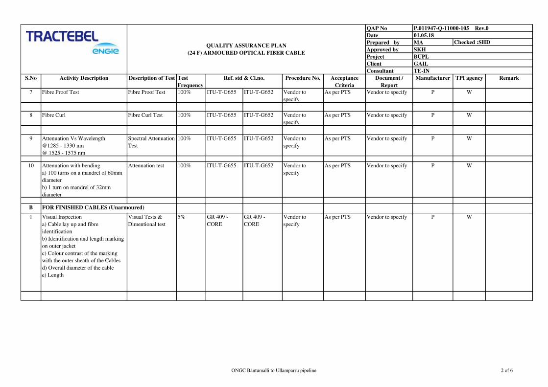
QAP No
Date
Prepared by MA
Approved by
Project
Client
Consultant
S.No Activity Description Description of Test Test
Frequency
Procedure No. Acceptance
Criteria
Document /
Report
Manufacturer TPI agency Remark
TE-IN
P.011947-Q-11000-105 Rev.0
01.05.18
SKH
Checked :SHDQUALITY ASSURANCE PLAN
(24 F) ARMOURED OPTICAL FIBER CABLE
Ref. std & Cl.no.
BUPL
GAIL
7 Fibre Proof Test Fibre Proof Test 100% ITU-T-G655 ITU-T-G652 Vendor to
specify
As per PTS Vendor to specify P W
8 Fibre Curl Fibre Curl Test 100% ITU-T-G655 ITU-T-G652 Vendor to
specify
As per PTS Vendor to specify P W
9 Attenuation Vs Wavelength
@1285 - 1330 nm
@ 1525 - 1575 nm
Spectral Attenuation
Test
100% ITU-T-G655 ITU-T-G652 Vendor to
specify
As per PTS Vendor to specify P W
10 Attenuation with bending
a) 100 turns on a mandrel of 60mm
diameter
b) 1 turn on mandrel of 32mm
diameter
Attenuation test 100% ITU-T-G655 ITU-T-G652 Vendor to
specify
As per PTS Vendor to specify P W
B
1 Visual Inspection
a) Cable lay up and fibre
identification
b) Identification and length marking
on outer jacket
c) Colour contrast of the marking
with the outer sheath of the Cables
d) Overall diameter of the cable
e) Length
Visual Tests &
Dimentional test
5% GR 409 -
CORE
GR 409 -
CORE
Vendor to
specify
As per PTS Vendor to specify P W
FOR FINISHED CABLES (Unarmoured)
ONGC Bantumalli to Ullamparru pipeline 2 of 6

QAP No
Date
Prepared by MA
Approved by
Project
Client
Consultant
S.No Activity Description Description of Test Test
Frequency
Procedure No. Acceptance
Criteria
Document /
Report
Manufacturer TPI agency Remark
TE-IN
P.011947-Q-11000-105 Rev.0
01.05.18
SKH
Checked :SHDQUALITY ASSURANCE PLAN
(24 F) ARMOURED OPTICAL FIBER CABLE
Ref. std & Cl.no.
BUPL
GAIL
2 Tests for Moisture barrier
a) Thickness of layers
b) Extent of overlapping
c) Electrical Continuity of metallic
layer
d) Water swellable tape on power
e) Water immersion
Moisture barrier
tests
a) 5%
b) 5%
c) 100%
d) 100%
GR-20 -CORE
IEC - 60793 -
1 - 53
GR-20-CORE
IEC - 60793 - 1
- 53
Vendor to
specify
As per PTS Vendor to specify P W
3 Tensile Performance
(Tensile load of 9.81 W Newton or
2700 N whichever is higher , Where
W = weight of 1Km Cable in Kg)
Tensile Test 5% IEC - 794 - 1 -
E1
IEC - 794 - 1 -
E1
Vendor to
specify
As per PTS Vendor to specify P W
4 Crush
(200Kg of load to be slowly placed
and held for 60 sec)
Crush Test 5% IEC - 794 - 1 -
E3
IEC - 794 - 1 -
E3
Vendor to
specify
As per PTS Vendor to specify P W
5 Impact
(Mass of 5 Kg to fall freely from
500mm height on the cable sample
10 times repeatedly with a gap
between 1 impact to another approx.
at 60 sec)
Impact Test 5% IEC - 794 - 1 -
E4
IEC - 794 - 1 -
E4
Vendor to
specify
As per PTS Vendor to specify P W
6 Torsion
(Weight of 7.5Kg attached to the
stationary chuck and shall be
subjected to 10 cycles)
Torsion Test 5% IEC - 794 - 1 -
E7
IEC - 794 - 1 -
E7
Vendor to
specify
As per PTS Vendor to specify P W
ONGC Bantumalli to Ullamparru pipeline 3 of 6
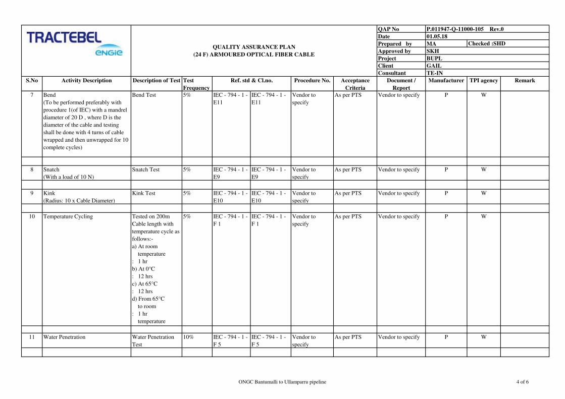
QAP No
Date
Prepared by MA
Approved by
Project
Client
Consultant
S.No Activity Description Description of Test Test
Frequency
Procedure No. Acceptance
Criteria
Document /
Report
Manufacturer TPI agency Remark
TE-IN
P.011947-Q-11000-105 Rev.0
01.05.18
SKH
Checked :SHDQUALITY ASSURANCE PLAN
(24 F) ARMOURED OPTICAL FIBER CABLE
Ref. std & Cl.no.
BUPL
GAIL
7 Bend
(To be performed preferably with
procedure 1(of IEC) with a mandrel
diameter of 20 D , where D is the
diameter of the cable and testing
shall be done with 4 turns of cable
wrapped and then unwrapped for 10
complete cycles)
Bend Test 5% IEC - 794 - 1 -
E11
IEC - 794 - 1 -
E11
Vendor to
specify
As per PTS Vendor to specify P W
8 Snatch
(With a load of 10 N)
Snatch Test 5% IEC - 794 - 1 -
E9
IEC - 794 - 1 -
E9
Vendor to
specify
As per PTS Vendor to specify P W
9 Kink
(Radius: 10 x Cable Diameter)
Kink Test 5% IEC - 794 - 1 -
E10
IEC - 794 - 1 -
E10
Vendor to
specify
As per PTS Vendor to specify P W
10 Temperature Cycling Tested on 200m
Cable length with
temperature cycle as
follows:-
a) At room
temperature
: 1 hr
b) At 0°C
: 12 hrs
c) At 65°C
: 12 hrs
d) From 65°C
to room
: 1 hr
temperature
5% IEC - 794 - 1 -
F 1
IEC - 794 - 1 -
F 1
Vendor to
specify
As per PTS Vendor to specify P W
11 Water Penetration Water Penetration
Test
10% IEC - 794 - 1 -
F 5
IEC - 794 - 1 -
F 5
Vendor to
specify
As per PTS Vendor to specify P W
ONGC Bantumalli to Ullamparru pipeline 4 of 6

QAP No
Date
Prepared by MA
Approved by
Project
Client
Consultant
S.No Activity Description Description of Test Test
Frequency
Procedure No. Acceptance
Criteria
Document /
Report
Manufacturer TPI agency Remark
TE-IN
P.011947-Q-11000-105 Rev.0
01.05.18
SKH
Checked :SHDQUALITY ASSURANCE PLAN
(24 F) ARMOURED OPTICAL FIBER CABLE
Ref. std & Cl.no.
BUPL
GAIL
12 Water Immersion Water Immersion
test
5% IEC - 60793 -
53
IEC - 60793 -
53
Vendor to
specify
As per PTS Vendor to specify P W
14 Sheath Integraty (Spark test) As Per PTS One
Closure
GR.No. G/OJC
- 01 / 01 AUG
92
GR.No. G/OJC -
01 / 01 AUG 92
Vendor to
specify
As per PTS Vendor to specify P W
15 1. Polarization Mode Dispersion
2. Abrasion Test
3. Flexural Rigidity Test on the
optical fibre cable
4. Test of Figure of 8 (Eight) on the
cable
5. Cable Aging Test
6. Check of easy removal of sheath
7. Effect of aggressive media on the
cable surface (Acidic and Alkaline
behavior)
8. Check of the Quality of the Loose
Tube (Containing Optical Fibre)
9. Drainage Test for Loose Tube and
Drip Test on the Cable
As Per PTS 5% GR.No. G/OJC
- 01 / 01 AUG
92
GR.No. G/OJC -
01 / 01 AUG 92
Vendor to
specify
As per PTS Vendor to specify P W
C
1 Water Ingress Test As Per PTS One
Closure
GR.No. G/OJC
- 01 / 01 AUG
GR.No. G/OJC -
01 / 01 AUG 92
Vendor to
specify
As per PTS Vendor to specify P W
2 Impact Test As Per PTS One
Closure
GR.No. G/OJC
- 01 / 01 AUG
GR.No. G/OJC -
01 / 01 AUG 92
Vendor to
specify
As per PTS Vendor to specify P W
3 Drop and Topple test As Per PTS One
Closure
GR.No. G/OJC
- 01 / 01 AUG
GR.No. G/OJC -
01 / 01 AUG 92
Vendor to
specify
As per PTS Vendor to specify P W
4 Pulling Test As Per PTS One
Closure
GR.No. G/OJC
- 01 / 01 AUG
GR.No. G/OJC -
01 / 01 AUG 92
Vendor to
specify
As per PTS Vendor to specify P W
FOR JOINT CLOSURES
ONGC Bantumalli to Ullamparru pipeline 5 of 6

QAP No
Date
Prepared by MA
Approved by
Project
Client
Consultant
S.No Activity Description Description of Test Test
Frequency
Procedure No. Acceptance
Criteria
Document /
Report
Manufacturer TPI agency Remark
TE-IN
P.011947-Q-11000-105 Rev.0
01.05.18
SKH
Checked :SHDQUALITY ASSURANCE PLAN
(24 F) ARMOURED OPTICAL FIBER CABLE
Ref. std & Cl.no.
BUPL
GAIL
5 Static Load Test As Per PTS One
Closure
GR.No. G/OJC
- 01 / 01 AUG
92
GR.No. G/OJC -
01 / 01 AUG 92
Vendor to
specify
As per PTS Vendor to specify P W
LEGEND :
R : Review
W : Witness
P : Perform
WR : Vendor Witness
TPIA : Third Party Inspection
Agency
Notes :
1) The above mentioned testing and acceptance criteria are minimum requirements for Optical Fiber Cable complying ITU-T 652 and 655 specifications , however
, supplier shall ensure that the product also comply to the additional requirements as per technical specifications and data sheets.
2) The supplier shall submit their own detailed QAP prepared on the basis of the above for approval of Owner / Owner's representative and TPIA. Any item
deemed to have been left out may also be included in the QAP of the vendor.
3) TPIA shall have right to inspect minimum 10% of all manufacturing activities on each day or as apecified above.
4) TPIA along with Owner / Owner's representative shall review / approve all the documents related to QAP / Quality manuals Drawings etc. submitted by
supplier.
5) TPIA shall also review the test certificates submitted by the manufacturer.
6) Supplier shall in coordination with sub vendor shall issue detailed production and inspection schedule indicating the dates and the locations to facilitate Owner /
Owner's representative to organise Inspection.
7) Supplier shall submit their own Detailed QAP Duly Signed and Stamped.
ONGC Bantumalli to Ullamparru pipeline 6 of 6

QAP No
Date
Prepared by MA
Approved by
Project
Client
Consultant
S.No Activity Description Description of Test Test Frequency Ref. std & Cl.no. Procedure No. Acceptance Criteria Document / Report ManufacturerTPI
agency
Control
Authority
1 Dimension Dimensional outside
diameter wall thickness
As Per Table 1 of GR /
CDS - 08 / 02 NOV
2004
GR / CDS - 08 / 02
NOV 2004
Vendor to Specify As Per PTS and
GR / CDS - 08 / 02 NOV
2004
Vendor to Specify P W W / R
2 Ovality Dimensional outside
Diameter
As Per Table 1 of GR /
CDS - 08 / 02 NOV
2004
GR / CDS - 08 / 02
NOV 2004
Vendor to Specify As Per PTS and
GR / CDS - 08 / 02 NOV
2004
Vendor to Specify P W W / R
3 Tensile Strength Tensile Elongation
Property
As Per Table 2 of GR /
CDS - 08 / 02 NOV
2004
GR / CDS - 08 / 02
NOV 2004
Vendor to Specify As Per PTS and
GR / CDS - 08 / 02 NOV
2004
Vendor to Specify P W W / R
4 Reversion Test Shrinkage As Per Table 2 of GR /
CDS - 08 / 02 NOV
2004
GR / CDS - 08 / 02
NOV 2004
Vendor to Specify As Per PTS and
GR / CDS - 08 / 02 NOV
2004
Vendor to Specify P W W / R
5 Environmental Stress Crack
Resistance
Chemical Property of
Product
As Per Table 2 of GR /
CDS - 08 / 02 NOV
2004
GR / CDS - 08 / 02
NOV 2004 & ASTM D
- 1693
Vendor to Specify As Per PTS and
GR / CDS - 08 / 02 NOV
2004
Vendor to Specify P W W / R
6 Impact Strength Impact Strength Test As Per Table 2 of GR /
CDS - 08 / 02 NOV
2004
GR / CDS - 08 / 02
NOV 2004
Vendor to Specify As Per PTS and
GR / CDS - 08 / 02 NOV
2004
Vendor to Specify P W W / R
7 Crush Resistance Test Deflection of Duct As Per Table 2 of GR /
CDS - 08 / 02 NOV
2004
GR / CDS - 08 / 02
NOV 2004
Vendor to Specify As Per PTS and
GR / CDS - 08 / 02 NOV
2004
Vendor to Specify P W W / R
8 Mandrel Test Internal Dia of Duct As Per Table 2 of GR /
CDS - 08 / 02 NOV
2004
GR / CDS - 08 / 02
NOV 2004
Vendor to Specify As Per PTS and
GR / CDS - 08 / 02 NOV
2004
Vendor to Specify P W W / R
9 Oxidation Induction Test Oxidation of HDPE
material
As Per Table 2 of GR /
CDS - 08 / 02 NOV
2004
GR / CDS - 08 / 02
NOV 2004
Vendor to Specify As Per PTS and
GR / CDS - 08 / 02 NOV
2004
Vendor to Specify P W W / R
10 Hydraulic Characteritic Test Leakage , Swelling ,
Weeping and Brust and
Crack in test duration
As Per Table 2 of GR /
CDS - 08 / 02 NOV
2004
GR / CDS - 08 / 02
NOV 2004
Vendor to Specify As Per PTS and
GR / CDS - 08 / 02 NOV
2004
Vendor to Specify P W W / R
11 Internal Co- efficient of friction Co-efficient of friction
HDPE material
As Per Table 2 of GR /
CDS - 08 / 02 NOV
2004
GR / CDS - 08 / 02
NOV 2004
Vendor to Specify As Per PTS and
GR / CDS - 08 / 02 NOV
2004
Vendor to Specify P W W / R
BUPL
GAIL
TE-IN
QUALITY ASSURANCE PLAN
PLB - HDPE DUCT
P.011947-Q-11000-106 Rev.0
Checked :SHD
01.05.18
SKH
ONGC Bantumalli to Ullamparru pipeline 1 of 3

QAP No
Date
Prepared by MA
Approved by
Project
Client
Consultant
S.No Activity Description Description of Test Test Frequency Ref. std & Cl.no. Procedure No. Acceptance Criteria Document / Report ManufacturerTPI
agency
Control
Authority
BUPL
GAIL
TE-IN
QUALITY ASSURANCE PLAN
PLB - HDPE DUCT
P.011947-Q-11000-106 Rev.0
Checked :SHD
01.05.18
SKH
12 Ash Content Ash content of finished
products
As Per PTS and
GR / CDS - 08 / 02
NOV 2004
GR / CDS - 08 / 02
NOV 2004
Vendor to Specify As Per PTS and
GR / CDS - 08 / 02 NOV
2004
Vendor to Specify P W W / R
13 Maximum Pulling Strength Pulling force on coupler As Per PTS and
GR / CDS - 08 / 02
NOV 2004
GR / CDS - 08 / 02
NOV 2004
Vendor to Specify As Per PTS and
GR / CDS - 08 / 02 NOV
2004
Vendor to Specify P W W / R
14 UV Stabiliser of content of Resin Identification of UV
additive
As Per PTS and
GR / CDS - 08 / 02
NOV 2004
GR / CDS - 08 / 02
NOV 2004
Vendor to Specify As Per PTS and
GR / CDS - 08 / 02 NOV
2004
Vendor to Specify P W W / R
15 UV Stabiliser of content of Duct As Per PTS As Per PTS and
GR / CDS - 08 / 02
NOV 2004
GR / CDS - 08 / 02
NOV 2004
Vendor to Specify As Per PTS and
GR / CDS - 08 / 02 NOV
2004
Vendor to Specify P W W / R
16 Fading of colour of Duct GR / ASTM D - 1712 As Per PTS and
GR / CDS - 08 / 02
NOV 2004
GR / CDS - 08 / 02
NOV 2004
Vendor to Specify As Per PTS and
GR / CDS - 08 / 02 NOV
2004
Vendor to Specify P W W / R
17 Bending Radius As Per PTS and
GR / CDS - 08 / 02 NOV
2004
As Per PTS and
GR / CDS - 08 / 02
NOV 2004
GR / CDS - 08 / 02
NOV 2004
Vendor to Specify As Per PTS and
GR / CDS - 08 / 02 NOV
2004
Vendor to Specify P W W / R
18 Thickness of inner lubricant As Per PTS and
GR / CDS - 08 / 02 NOV
2004
As Per PTS and
GR / CDS - 08 / 02
NOV 2004
GR / CDS - 08 / 02
NOV 2004
Vendor to Specify As Per PTS and
GR / CDS - 08 / 02 NOV
2004
Vendor to Specify P W W / R
19 Density of finished product As Per PTS As Per IS 7328 As Per IS 7328 Vendor to Specify As Per PTS Vendor to Specify P W W / R
20 Melt flow rate of finished duct As Per PTS As Per IS 2530 As Per IS 2530 Vendor to Specify As Per PTS Vendor to Specify P W W / R
21 Change in MFR As Per PTS AS Per GR / CDS - 08 /
02 NOV 2004
GR / CDS - 08 / 02
NOV 2004
Vendor to Specify As Per PTS Vendor to Specify P W W / R
LEGEND :
R : Review
W : Witness
P : Perform
TPIA : Third Party Inspection
Agency
ONGC Bantumalli to Ullamparru pipeline 2 of 3

QAP No
Date
Prepared by MA
Approved by
Project
Client
Consultant
S.No Activity Description Description of Test Test Frequency Ref. std & Cl.no. Procedure No. Acceptance Criteria Document / Report ManufacturerTPI
agency
Control
Authority
BUPL
GAIL
TE-IN
QUALITY ASSURANCE PLAN
PLB - HDPE DUCT
P.011947-Q-11000-106 Rev.0
Checked :SHD
01.05.18
SKH
Notes :
1) The above mentioned testing and acceptance criteria are minimum requirements , however , supplier shall ensure that the product also comply to the additional requirements as per
technical specifications and data sheets.
2) The supplier shall submit their own detailed QAP prepared on the basis of the above for approval of Owner / Owner's representative and TPIA.
3) TPIA shall have right to inspect minimum 10% of all manufacturing activities on each day or as apecified above.
4) TPIA along with Owner / Owner's representative shall review / approve all the documents related to QAP / Quality manuals Drawings etc. submitted by supplier.
5) TPIA shall also review the test certificates submitted by the manufacturer.
6) Supplier shall in coordination with sub vendor shall issue detailed production and inspection schedule indicating the dates and the locations to facilitate Owner / Owner's representative to
organise Inspection.
7) Supplier shall submit their own Detailed QAP Duly Signed and Stamped.
ONGC Bantumalli to Ullamparru pipeline 3 of 3

QAP No
Date
Prepared by MA Checked by : SHD
Approved by
Project
Client
Consultant
SL. No.Component/Operatio
nCharachteristics Type of Check
Quantum of
CheckReference Doc Acceptance Norms
1Raw Material
Inspection
Manifacturer
/Vendor
Contractor's
TPIARemark
1. Surface Finish Visual
2. Diameter/Dimension Physical
3. Resistance Electrical
4. Chemical property (Persulphate test
for tinned copper )Chemical
5. Annealing Test Physical
1. Tensile & Elongation before &
after ageingVisual
2. Type of compound Visual
3. Thermal Stability Physical
1. Oxygen Index Enviro Min. 30%
2. Temperature Index Enviro Min 250deg C
1. Surface Condition Visual
2. Uniformity of Zinc Coating Chemical
3. Tensile strength & elongation Physical
4. Torsion/ Winding Physical
2 Process Inspection
1. Type of Material Visual
2. Thickness of Insulation (Avg.
Min.)Physical
3. Core Identification Visual
4. Surface Finish Visual
5. Spark test Electrical
6. Volume Resistivity Electrical
1. Sequence of laying Visual
2. Continuity of conductor Electrical
3. Continuity of common pair Electrical
4. Dimension Physical
5. Lay Length Physical
1. Tape thickness Physical
2. Tape overlap Visual
3. Drain wire size Physical
QUALITY ASSURANCE PLAN
FOR
INSTRUMENT CABLES
P.011947-Q-11000-107 Rev.0
01.05.18
SKH
BUPL
GAIL
TE-IN
Each setting &
during run of
M/c
Inspection Agency
100% Sample
IS 8130/ BS 5308(P-2) &
Relevant Standard as per
Specification
IS 8130/ BS 5308(P-2)
Relevant Standard as per
Specification
One sample per
batch
IS 5831/ BS 5308(P-
2)Relevant Standard as per
Specification
IS 5831/ BS 5308(P-
2)Relevant Standard as per
Specification
ASTM-D2863
P
Copper / Aluminium
wire (As Applicable)
Insulation & Sheathing
compound1.2
FR Test for FR PVC
only
1.1
One sample per
batch
IS 3975/ BS 5308(P-2)
Relevant Standard as per
Specification
IS 3975/ BS 5308(P-2)
Relevant Standard as per
Specification
P R
R
Insulated core2.1
Pair/Triad screeing &
Overall screeing
2.2
2.3
Armour-Galvanised
steel round wire/strip1.3
P R
P R
Pair/Triad- laying
Setting &
During Process BS 5308(P-2) & Relevant
Standard as per
Specification
BS 5308(P-2) & Relevant
Standard as per
Specification
P R
P R
ONGC Bantumalli to Ullamparru pipeline 1 of 4

QAP No
Date
Prepared by MA Checked by : SHD
Approved by
Project
Client
Consultant
SL. No.Component/Operatio
nCharachteristics Type of Check
Quantum of
CheckReference Doc Acceptance Norms
QUALITY ASSURANCE PLAN
FOR
INSTRUMENT CABLES
P.011947-Q-11000-107 Rev.0
01.05.18
SKH
BUPL
GAIL
TE-IN
Inspection Agency
1. Type of PVC Visual
2. Dimension Physical
3. Thickness of Inner Sheath Physical
4. Surface finish & Colour Visual
5. Embossing/ Printing/Sequential
Markingon outer sheathVisual
1. No. of strips/wires Visual
2. Dimension of strips/wires Physical
3. Direction of lay Visual
1. Make up Visual
No. of strands counting
2. Size/Dimensions Physical
3. DC Resistance at 20deg C Electrical
Annealing (Before stranding) for
copperPhysical
1. Conductor Resistance Electrical 100% Drums
IS 8130/ BS 5308(P-2) &
Relevant Standard as per
Specification
IS 8130/ BS 5308(P-2) &
Relevant Standard as per
Specification
P W
2. Mutual Capacitance Electrical 10% Drums
3. Capacitance between core & screen Electrical 10% Drums
4. L/R Ratio Electrical 10% Drums
5. HV Test
a) Core to core
b) Core to shield/Armour
Electrical 100% Drums
6. Spark Test
a. Core
b. Sheath
BS 5308(P-2) / BS 5099
& Relevant Standard as
per Specification
Relevant Standard as per
SpecificationP W
7. Test for rodent & termite repulsion P W
1. HV Test
a) Core to core
b) Core to shield/Armour
Electrical 10% Sample
BS 5308(P-2) & Relevant
Standard as per
Specification
BS 5308(P-2) & Relevant
Standard as per
Specification
2. Conductor Resistance Electrical 10% Sample
IS 8130/ BS 5308(P-2) &
Relevant Standard as per
Specification
IS 8130/ BS 5308(P-2) &
Relevant Standard as per
Specification
BS 5308(P-2) & Relevant
Standard as per
Specification
BS 5308(P-2) & Relevant
Standard as per
Specification
IS 8130/ BS 5308(P-2) &
Relevant Standard as per
Specification
IS 8130/ BS 5308(P-2)
Relevant Standard as per
Specification
Each setting &
at the running
of M/c
Starting of M/c
& during
process
Routine Test3
2.8 Conductor
Inner sheath and outer
sheath2.6
Armouring2.7
WP
P R
P R
P R
100% spools at
start & end
ONGC Bantumalli to Ullamparru pipeline 2 of 4

QAP No
Date
Prepared by MA Checked by : SHD
Approved by
Project
Client
Consultant
SL. No.Component/Operatio
nCharachteristics Type of Check
Quantum of
CheckReference Doc Acceptance Norms
QUALITY ASSURANCE PLAN
FOR
INSTRUMENT CABLES
P.011947-Q-11000-107 Rev.0
01.05.18
SKH
BUPL
GAIL
TE-IN
Inspection Agency
3. Continuity test Electrical 10% Sample
4. Insulation Resistance (Before &
After HV)
a. Individual Conductor
b. Individual Screens
ElectricalOne sample per
lot
5. Tensile Strength & Elongation for
Insulation & sheath before ageingPhysical 10% Sample
6. Dimension Visual 10% Sample
7. Cable Capacitance between core &
screen & L/R ratio testElectrical 10% Sample
8. Spark Test
a. Core
b. Sheath
BS 5308(P-2) / BS 5099
& Relevant Standard as
per Specification
Relevant Standard as per
Specification
9. Test for rodent & termide
repulsion.Chemical
One sample per
lot" "
10. Uniformity of zinc coating on
armourChemical " " "
11. Oxygen Index test as per
ASTMD:2863Chemical " " "
12. Temperature Index test as per
ASTMD:2864Chemical " " "
13. FR test as per IS:10810 Thermal " " "
14. Overall finish & drum length Visual " " "
1. Oxygen Index Enviro Min. 30%
2. Temperature Index Enviro Min 250deg C
3. Flammability test Fire IEC 332-1 Shall Pass
4. Smoke Density As Applicable ASTM 2843
5. Acid Gas Generation As Applicable IEC-754-1
6. Swedish Chimmney Test As Applicable As per Relevant Staandard
6 Type Test
1. Conductor Resistance Electrical
IS 8130/ BS 5308(P-2) &
Relevant Standard as per
Specification
IS 8130/ BS 5308(P-2) &
Relevant Standard as per
Specification
P R
Tests For Conductor6.1
Acceptance Test4
Flammability Test for
FRLS PVC only5 P W
P W
One sample per
BS 5308(P-2) & Relevant
Standard as per
Specification
BS 5308(P-2) & Relevant
Standard as per
Specification
One sample per
lot
ASTM-D2863
ONGC Bantumalli to Ullamparru pipeline 3 of 4

QAP No
Date
Prepared by MA Checked by : SHD
Approved by
Project
Client
Consultant
SL. No.Component/Operatio
nCharachteristics Type of Check
Quantum of
CheckReference Doc Acceptance Norms
QUALITY ASSURANCE PLAN
FOR
INSTRUMENT CABLES
P.011947-Q-11000-107 Rev.0
01.05.18
SKH
BUPL
GAIL
TE-IN
Inspection Agency
2. Annealing Test on Cu Physical
BS 6360 & Relevant
Standard as per
Specification
BS 6360 & Relevant
Standard as per
Specification
P R
1. Tensile strength Physical
2. % Elongation Physical
3. Torsion/Winding Physical
4. Wt. of zinc coating Chemical
5. Dimensions Physical
6. Uniformity of coating Chemical
6.3Thickness of Insulation
& SheathThickness of Insulation & Sheath Physical
One sample per
lot
BS 5308(P-2) & Relevant
Standard as per
Specification
BS 5308(P-2) & Relevant
Standard as per
Specification
P R
1. Elongation & T. S. Before & After
AgeingPhysical
2. Ageing in Air oven Physical
3. Shrinkage test Physical
4. Hot Deformation Physical
5. Heat Shock Physical
6. Thermal stability Physical
7. Flammability Test Physical
8. Loss of Mass Physical
6.5
Insulation Resistance
test at room & rated
temperature
Volume resistivity ElectricalOne sample per
lot
BS 5308(P-2) & Relevant
Standard as per
Specification
BS 5308(P-2) & Relevant
Standard as per
Specification
P R
6.6H.V. test at room
temperatureH.V. test at room temperature Electrical
One sample per
lot
BS 5308(P-2) & Relevant
Standard as per
Specification
BS 5308(P-2) & Relevant
Standard as per
Specification
P R
6.7 Noise Test Electrostatic noise rejection ratio test ElectricalOne sample per
lot
BS 5308(P-2) & Relevant
Standard as per
Specification
BS 5308(P-2) & Relevant
Standard as per
Specification
P R
Finish
Marking on drum
C: Critical M-Manufacturer,
W: Witness
Visual
Tests For Conductor6.1
6.2Test on Armour
wire/strip
lot
One sample per
lot
BS 5308(P-2) & Relevant
Standard as per
Specification
P R
BS 5308(P-2) & Relevant
Standard as per
Specification
P-Perfomer,LEGEND: R: Review of Docs B: Major RW-Random witness
A: Minor TPIA-Third Party Inspection Agency H-HOLD
As per Relevant Standard100% As per Relevant Standard P R
One sample per
lot
BS 5308(P-2) & Relevant
Standard as per
Specification
BS 5308(P-2) & Relevant
Standard as per
Specification
P R6.4
Physical tests on
Insulation & Outer
Sheath
packing in drum7
ONGC Bantumalli to Ullamparru pipeline 4 of 4

QAP No
Date
Prepared by MA Checked by : SHD
Approved by
Project
Client
Consultant
Manifacturer
/VendorTPIA Client
1
1.1
Material Identification, Visual,
Pressure test on castings for
hazardous area Junction boxes.
100% P R R
2
2.1 Visual, Dimensions 100% P R -
3
· Visual, dimensional, clearance
& Paint shade check for all items.
JB TAG no. Plate
· Verification of Terminal Nos.,
sizes and no. of entries
· Bill of material verification.
· Warning plate for junction
boxes and marking on cable
glands, Adapters, Plugs etc.
· Pressure test on casting for
flameproof junction boxes.
· High Voltage and insulation
resistance test.
· Air leak test report on
pneumatic JBs.
4
3.1100% by
SupplierFinal Inspection
Painting
Remark
QUALITY ASSURANCE PLAN
FOR
JUNCTION BOX
P.011947-Q-11000-108 Rev.0
01.05.18
SKH
BUPL
GAIL
TE-IN
Sl.No Description CharacterisitcQuantum of
CheckRecord
Inspection Agency
Machining of components
Final Inspection
Material Test Certificates /
Lab test certificates /Relevant
Standard as per Specification
Test Records / Relevant
Standard as per Specification
Material Inspection
Incoming materials like
Castings, Terminals etc.
In process Inspection
W/R
Supplier’s Test Records /
Relevant Standard as per
Specification
WP
ONGC Bantumalli to Ullamparru pipeline Page 1 of 2
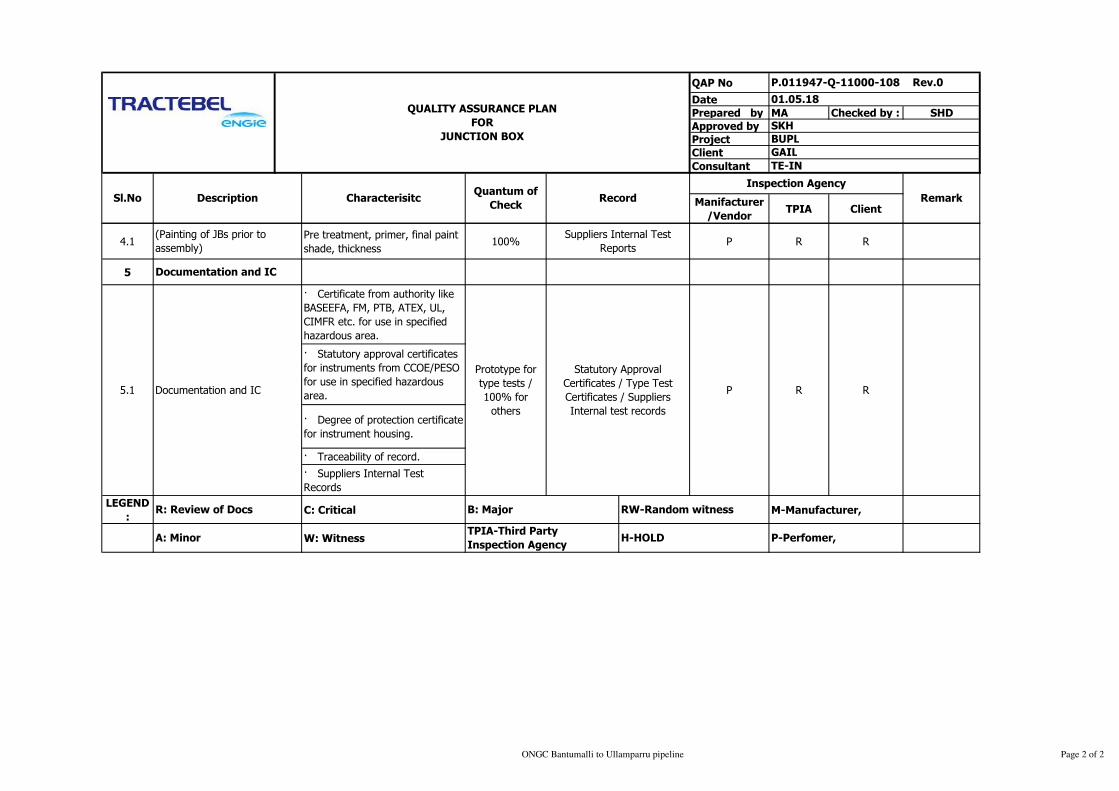
QAP No
Date
Prepared by MA Checked by : SHD
Approved by
Project
Client
Consultant
Manifacturer
/VendorTPIA Client
Remark
QUALITY ASSURANCE PLAN
FOR
JUNCTION BOX
P.011947-Q-11000-108 Rev.0
01.05.18
SKH
BUPL
GAIL
TE-IN
Sl.No Description CharacterisitcQuantum of
CheckRecord
Inspection Agency
4.1Pre treatment, primer, final paint
shade, thickness100% P R R
5
· Certificate from authority like
BASEEFA, FM, PTB, ATEX, UL,
CIMFR etc. for use in specified
hazardous area.
· Statutory approval certificates
for instruments from CCOE/PESO
for use in specified hazardous
area.
· Degree of protection certificate
for instrument housing.
· Traceability of record.
· Suppliers Internal Test
Records
LEGEND
: C: Critical M-Manufacturer,
W: Witness
(Painting of JBs prior to
assembly)
5.1
Prototype for
type tests /
100% for
others
P
Documentation and IC
Documentation and IC
Statutory Approval
Certificates / Type Test
Certificates / Suppliers
Internal test records
R
Suppliers Internal Test
Reports
R
P-Perfomer,
R: Review of Docs
A: Minor H-HOLD
B: Major
TPIA-Third Party
Inspection Agency
RW-Random witness
ONGC Bantumalli to Ullamparru pipeline Page 2 of 2

QAP No
Date
Prepared by MA Checked by SHD
Approved by
Project
Client
Consultant
Manifacturer
/VendorTPIA Client
1.0 Material Inspection
1
Incoming materials like Gas
detectors, Gas monitors /
Controllers, Portable gas
detectors, System cabinets,
Power supply units, Hooters,
Beacons, Data loggers,
Junction boxes etc.
Visual 100%Approved Datasheet /
Job Specification
Approved
Datasheet /
Job Specification
Manufacturer’s test
Certificates P R R
2.0 Final Inspection
2.1 Final Inspection Visual 100%Approved Datasheet /
Job Specification
Approved
Datasheet /
Job Specification
P W
Visual /
electrical100%
Approved Datasheet /
Job Specification
Approved
Datasheet /
Job Specification
P W
Visual /
electrical100%
Approved Datasheet /
Job Specification
Approved
Datasheet /
Job Specification
P W
Type of
CheckSL. No.
Functional Check
Make, Model Number
CharacteristicsComponent /
Operation
2.3
Calibration check of gas detectors including alarm,
repeatability, response time.
- Redundancy check for power supply units
-Functional check of gas monitors / controllers with gas
detectors.
Functional check of portable gas detectors
- Functional check of portable purge calibrators.
-Functional checks of GD system with PCs, Data loggers,
Printers, Hooters, Annunciators, Beacons etc.
-Verification of system diagnostics, System and application
software including Graphics (if configured), Interface with
third party devices.
-Performance test as per standard specification
P.011947-Q-11000-109 Rev.0
01.05.18
SKH
BUPL
Visual , Dimension check
- Bill of Material
- Tag Plates
- Wiring check of cabinets with all accessories
QUALITY ASSURANCE PLAN
FOR
GAS DETECTION SYSTEM
Inspection Agency
GAIL
TE-IN
Format of
Plan
Acceptance
Norm
Referrence
Document
Quantum of
Check
ONGC Bantumalli to Ullamparru pipeline Page 1 of 2

QAP No
Date
Prepared by MA Checked by SHD
Approved by
Project
Client
Consultant
Type of
CheckSL. No. Characteristics
Component /
Operation
P.011947-Q-11000-109 Rev.0
01.05.18
SKH
BUPL
QUALITY ASSURANCE PLAN
FOR
GAS DETECTION SYSTEM
Inspection Agency
GAIL
TE-IN
Format of
Plan
Acceptance
Norm
Referrence
Document
Quantum of
Check
2.4 Certification / Documents Visual
Prototype for
each model
100 %
Statutory Approval
Certificates/Type Test
Certificates
Statutory Approval
Certificates/Type
Test Certificates
P R
3 Packing Visual 100% Packing List P R
NOTE:
LEGEND: R: Review of Docs C: Critical B: Major RW-Random witness
A: Minor W: Witness TPIA-Third Party Inspection Agency H-HOLD
Visual check and Proper packing to prevent entry of foreign
material
Certificate from testing agency like BASEEFA, FM, PTB,
CIMFR etc. for instruments for gas detectors, portable
detectors, junction boxes etc. for use in specified hazardous
area
- BIS approval for gas detectors, junction boxes etc.
manufactured indigenously for use in specified hazardous
area.
- Statutory approval certificates for instruments from
CCOE/PESO for use in specified hazardous area.
- Degree of protection certificate for instrument housing.
- Electromagnetic & Radio frequency compatibility
requirements for gas detectors, gas monitors/controllers.
-Test certificate for calibration gases
ALL TESTING AND MEASURING EQUIPMENTS/INSTRUMENTS SHALL HAVE VALID CALIBRATION WITH CALIBRATION CERTIFICATES & TRACEABILITIES.
M-Manufacturer,
P-Perfomer,
ONGC Bantumalli to Ullamparru pipeline Page 2 of 2

QAP No
Date
Prepared by MA Checked by : SHD
Approved by
Project
Client
Consultant
Manifacturer
/VendorTPIA Client
1.0 Material Inspection
1Incoming sheet steel for
panel fabricationVisual 100%
Approved Datasheet /
Job Specification
Approved
Datasheet /
Job Specification
Manufacturer’s test
Certificates P R R
2.0 Final Inspection
2.1 Final InspectionVisual /
electrical100%
Approved Datasheet /
Job Specification
Approved
Datasheet /
Job Specification
P W R/W
2.2Certification / Documents as
pplicableVisual
Prototype for
each model
100 %
Statutory Approval
Certificates/Type Test
Certificates
Statutory Approval
Certificates/Type
Test Certificates
P R R
3 Packing Visual 100% Packing List P R -
4Documentation and
inspection certificateVisual 100%
Supplier test
records/Inspection
certificate
Supplier test
records/Inspection
certificate
Supplier test
records/Inspection
certificate
P R R
NOTE:
LEGEND: R: Review of Docs C: Critical B: Major RW-Random witness
A: Minor W: Witness TPIA-Third Party Inspection Agency H-HOLD
P.011947-Q-11000-110 Rev.0
01.05.18
SKH
BUPL
Visual , Dimension check
- Bill of Material
- Tag Plates
- Wiring check of cabinets with all accessories
- High Voltage test and insulation test
- Functional check of instruments and accessories, shut
down & interlock system by simulation
- Earthing check
- component layout arrangement.
- Easy accessibility for maintenance/replacement of
components
QUALITY ASSURANCE PLAN
FOR
LOCAL CONTROL PANEL
Inspection Agency
GAIL
TE-IN
Format of
Plan
Acceptance
Norm
Referrence
Document
Quantum of
Check
ALL TESTING AND MEASURING EQUIPMENTS/INSTRUMENTS SHALL HAVE VALID CALIBRATION WITH CALIBRATION CERTIFICATES & TRACEABILITIES.
M-Manufacturer,
P-Perfomer,
Type of
CheckSL. No.
Review of internal test report
Certificates for all bought out component
Calibration test certificate for all instrument
Inspection certificate issuance
Certificate from testing agency like BASEEFA, FM, PTB,
CIMFR etc. for instruments use in specified hazardous area
- Statutory approval certificates for instruments from
CCOE/PESO for use in specified hazardous area.
- Degree of protection certificate for instrument housing.
- Electromagnetic & Radio frequency compatibility
requirements
Visual, Surface Finish, Dimensions, Chemical treatment.
CharacteristicsComponent /
Operation
Visual check and Proper packing to prevent entry of foreign
material
ONGC Bantumalli to Ullamparru pipeline Page 1 of 1
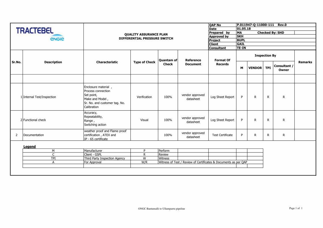
QAP No
Date
Prepared by MA Checked By: SHD
Approved by
Project
Client
Consultant
M VENDOR TPIConsultant /
Owner
1 Internal Test/Inspection
Enclosure material ,
Process connection
Set point,
Make and Model ,
Sr. No. and customer tag. No.
Calibration
Verification 100%vendor approved
datasheetLog Sheet Report P R R R
2 Functional check
Accuracy,
Repeatability,
Range ,
Switching action
Visual 100%vendor approved
datasheetLog Sheet Report P R R R
2 Documentation
weather proof and Flame proof
certification , ATEX and
IP - 65 certificate
100%vendor approved
datasheetTest Certificate P R R R
M Manufacturer P Perform
C Client - GSPL R Review
TPI Third Party Inspection Agency W Witness
A For Approval W/R Witness of Test / Review of Certificates & Documents as per QAP
Format Of
Records
Inspection By
Remarks
Legend
Sr.No. Description Characteristic Type of CheckQuantam of
Check
Reference
Document
SKH
BUPL
GAIL
QUALITY ASSURANCE PLAN
DIFFERENTIAL PRESSURE SWITCH
P.011947-Q-11000-111 Rev.0
01.05.18
TE-IN
ONGC Bantumalli to Ullamparru pipeline Page 1 of 1
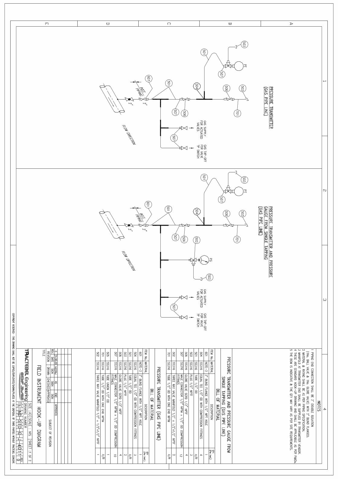


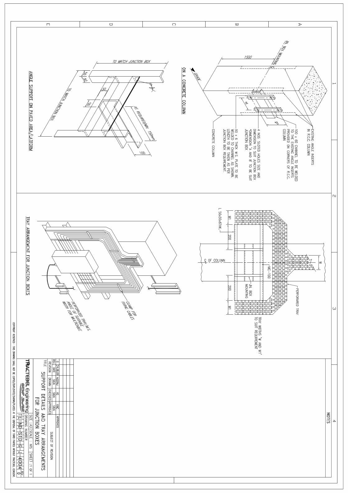


At the helm of the Energy Transition, Tractebel provides a full range of engineering and consulting servicesthroughout the life cycle of its clients’ projects, including design and project management. As one of the world’slargest engineering consultancy companies and with more than 150 years of experience, it's our mission to activelyshape the world of tomorrow. With about 4,400 experts and offices in 33 countries, we are able to offer ourcustomers multidisciplinary solutions in energy, water and infrastructure.
TRACTEBEL ENGINEERING PVT. LTD.Intec House 37Institutional Area, Sector 44122 002 - Gurgaon - INDIAtractebel-engie.com
Sunil KUMARtel. + 91 124 4712200fax + 91 124 [email protected]