launchxl-f28377s overview user's guide (rev. c) · launchxl-f28377s overview user's guide...
TRANSCRIPT
LAUNCHXL-F28377S Overview
User's Guide
Literature Number: SPRUI25CJune 2015–Revised April 2017
2 SPRUI25C–June 2015–Revised April 2017Submit Documentation Feedback
Copyright © 2015–2017, Texas Instruments Incorporated
Table of Contents
Contents
1 Trademarks ......................................................................................................................... 42 Introduction......................................................................................................................... 53 Kit Contents ........................................................................................................................ 64 Installation .......................................................................................................................... 6
4.1 Code Composer Studio ................................................................................................. 65 Getting Started with the LAUNCHXL-F28377S.......................................................................... 7
5.1 Getting Started ........................................................................................................... 75.2 Demo Application, ADC Sampling ..................................................................................... 75.3 Program and Debug the ADC Sample Demo Application .......................................................... 7
6 Hardware Configuration ........................................................................................................ 86.1 ADC Resolution .......................................................................................................... 86.2 Power Domain ............................................................................................................ 86.3 Boot Mode Selection..................................................................................................... 86.4 Connecting a BoosterPack.............................................................................................. 86.5 Device Migration Path ................................................................................................... 8
7 LAUNCHXL-F28377S Hardware .............................................................................................. 97.1 Device Pin Out............................................................................................................ 97.2 Schematics .............................................................................................................. 117.3 PCB Layout.............................................................................................................. 177.4 Bill of Materials (BOM) ................................................................................................. 18
8 References ........................................................................................................................ 229 Frequently Asked Questions (FAQ) ...................................................................................... 23Revision History.......................................................................................................................... 24
www.ti.com
3SPRUI25C–June 2015–Revised April 2017Submit Documentation Feedback
Copyright © 2015–2017, Texas Instruments Incorporated
List of Figures
List of Figures1 LAUNCHXL-F28377S Board Overview ................................................................................... 62 LAUNCHXL-F28377S_B Block Diagram Schematic .................................................................. 113 LAUNCHXL-F28377S XDS100v2 Schematic .......................................................................... 124 LAUNCHXL-F28377S Power Schematic................................................................................ 135 LAUNCHXL-F28377S_A Schematic..................................................................................... 146 LAUNCHXL-F28377S_B Schematic..................................................................................... 157 LAUNCHXL-F28377S BoosterPack Schematic ........................................................................ 168 Top Silk ...................................................................................................................... 179 Top Copper ................................................................................................................. 1710 Inner Copper 1.............................................................................................................. 1711 Inner Copper 2.............................................................................................................. 1712 Bottom Silk .................................................................................................................. 1713 Bottom Copper.............................................................................................................. 17
List of Tables1 F28377S LaunchPad Pin Out and Pin Mux Options - J1, J3 .......................................................... 92 F28377S LaunchPad Pin Out and Pin Mux Options - J4, J2 .......................................................... 93 F28377S LaunchPad Pin Out and Pin Mux Options - J5, J7......................................................... 104 F28377S LaunchPad Pin Out and Pin Mux Options - J8, J6......................................................... 105 LAUNCHXL-F28377S Bill of Materials .................................................................................. 18

www.ti.com
4 SPRUI25C–June 2015–Revised April 2017Submit Documentation Feedback
Copyright © 2015–2017, Texas Instruments Incorporated
List of Tables
1 TrademarksC2000, Delfino, LaunchPad, Code Composer Studio are trademarks of Texas Instruments.Windows is a registered trademark of Microsoft Corporation in the United States and/or other countries.All other trademarks are the property of their respective owners.
5SPRUI25C–June 2015–Revised April 2017Submit Documentation Feedback
Copyright © 2015–2017, Texas Instruments Incorporated
LAUNCHXL-F28377S Overview
User's GuideSPRUI25C–June 2015–Revised April 2017
LAUNCHXL-F28377S Overview
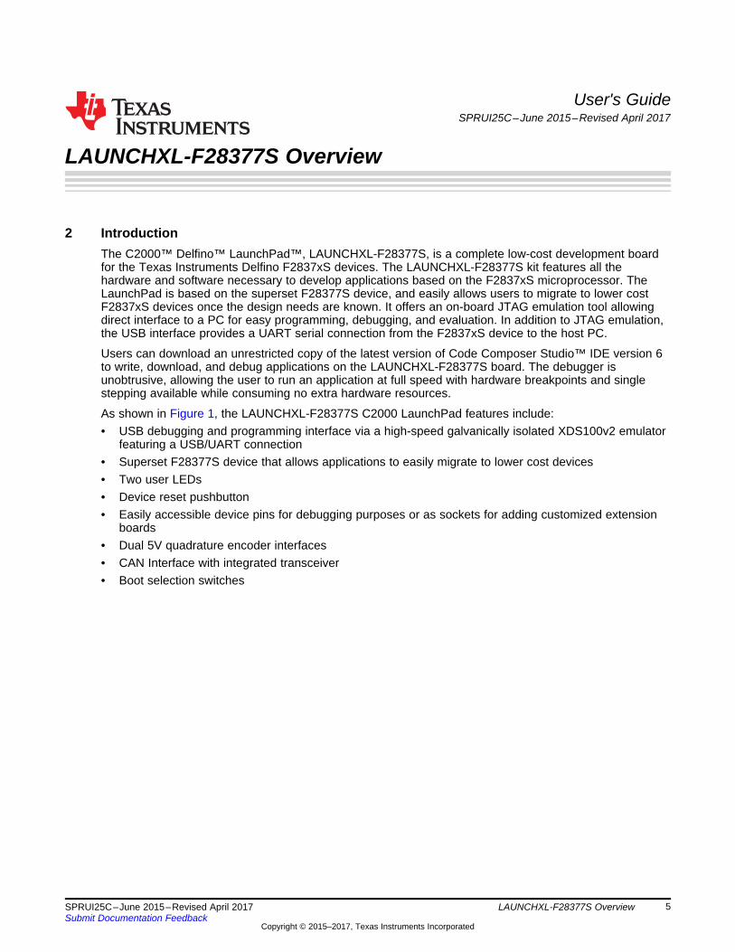
2 IntroductionThe C2000™ Delfino™ LaunchPad™, LAUNCHXL-F28377S, is a complete low-cost development boardfor the Texas Instruments Delfino F2837xS devices. The LAUNCHXL-F28377S kit features all thehardware and software necessary to develop applications based on the F2837xS microprocessor. TheLaunchPad is based on the superset F28377S device, and easily allows users to migrate to lower costF2837xS devices once the design needs are known. It offers an on-board JTAG emulation tool allowingdirect interface to a PC for easy programming, debugging, and evaluation. In addition to JTAG emulation,the USB interface provides a UART serial connection from the F2837xS device to the host PC.
Users can download an unrestricted copy of the latest version of Code Composer Studio™ IDE version 6to write, download, and debug applications on the LAUNCHXL-F28377S board. The debugger isunobtrusive, allowing the user to run an application at full speed with hardware breakpoints and singlestepping available while consuming no extra hardware resources.
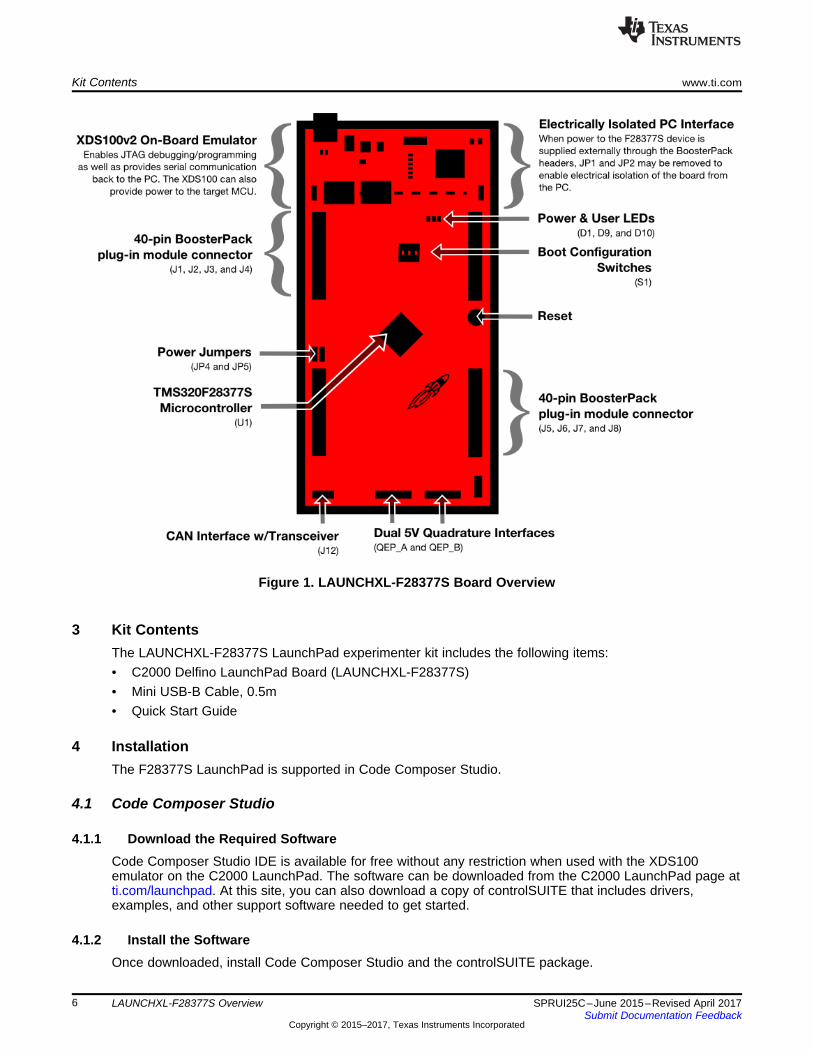
As shown in Figure 1, the LAUNCHXL-F28377S C2000 LaunchPad features include:• USB debugging and programming interface via a high-speed galvanically isolated XDS100v2 emulator
featuring a USB/UART connection• Superset F28377S device that allows applications to easily migrate to lower cost devices• Two user LEDs• Device reset pushbutton• Easily accessible device pins for debugging purposes or as sockets for adding customized extension
boards• Dual 5V quadrature encoder interfaces• CAN Interface with integrated transceiver• Boot selection switches
Kit Contents www.ti.com
6 SPRUI25C–June 2015–Revised April 2017Submit Documentation Feedback
Copyright © 2015–2017, Texas Instruments Incorporated
LAUNCHXL-F28377S Overview
Figure 1. LAUNCHXL-F28377S Board Overview
3 Kit ContentsThe LAUNCHXL-F28377S LaunchPad experimenter kit includes the following items:• C2000 Delfino LaunchPad Board (LAUNCHXL-F28377S)• Mini USB-B Cable, 0.5m• Quick Start Guide
4 InstallationThe F28377S LaunchPad is supported in Code Composer Studio.
4.1 Code Composer Studio
4.1.1 Download the Required SoftwareCode Composer Studio IDE is available for free without any restriction when used with the XDS100emulator on the C2000 LaunchPad. The software can be downloaded from the C2000 LaunchPad page atti.com/launchpad. At this site, you can also download a copy of controlSUITE that includes drivers,examples, and other support software needed to get started.
4.1.2 Install the SoftwareOnce downloaded, install Code Composer Studio and the controlSUITE package.
www.ti.com Getting Started with the LAUNCHXL-F28377S
7SPRUI25C–June 2015–Revised April 2017Submit Documentation Feedback
Copyright © 2015–2017, Texas Instruments Incorporated
LAUNCHXL-F28377S Overview
4.1.3 Install the HardwareAfter Code Composer Studio is installed, plug the supplied USB cable into the C2000 LaunchPad boardand into an available USB port on your computer.
Windows® will automatically detect the hardware and ask you to install software drivers. Let Windows runa search for the drivers and automatically install them. After Windows successfully installs the drivers forthe integrated XDS100v2 emulator, your LaunchPad is now ready for use.
5 Getting Started with the LAUNCHXL-F28377S
5.1 Getting StartedThe first time the LAUNCHXL-F28377S is used, a demo application automatically starts when the board ispowered from a USB host. If your board does not start the demo application, try placing S1 in the followingpositions and resetting the board: UP - UP - DOWN. To start the demo, connect the LAUNCHXL-F28377Swith the included mini-USB cable to a free USB port. The demo application starts with the LEDs flashingto show the device is active.
5.2 Demo Application, ADC SamplingThe LAUNCHXL-F28377S includes a pre-programmed TMS320F28377S device. When the LaunchPad isconnected via USB, the demo starts with an LED flash sequence. After a few seconds the device switchesinto an ADC sample mode.
Each second the ADC is sampled and the sample data is relayed to you. If the sample is above mid-scale(2048), the red LED will light. However, if the sample is below mid-scale the blue LED will light.
In addition to the LED display, sample information is also displayed on your PC through the USB/UARTconnection. To view the UART information on your PC, first figure out the COM port associated with theLaunchPad. To do this in Windows, right click on My Computer and click on Properties. In the dialog boxthat appears, click on the Hardware tab and open Device Manager. Look for an entry under Ports (COM &LPT) titled "USB Serial Port (COMX)", where X is a number. Remember this number for when you open aserial terminal. The demo applications UART data was written and debugged using PuTTY, and for thebest user experience we recommend you use PuTTY to view the UART data. PuTTY can be downloadedfrom the following URL:
http://www.chiark.greenend.org.uk/~sgtatham/putty/download.html
Open your serial terminal program and open the COM port you found previously in device manager withthe following settings: 115200 Baud, 8 data bits, no parity, 1 stop bit. After opening the serial port in yourserial terminal, reset the Launchpad with the reset push button and observe the serial terminal for asurprise.
5.3 Program and Debug the ADC Sample Demo ApplicationThe project and associated source code for the C2000 Delfino LaunchPad demo is included in thecontrolSUITE software package and should automatically be found by the TI Resource Explorer in CodeComposer Studio v6. In the resource explorer, open the controlSUITE folder and then the DevelopmentTools entry and look for the C2000 LaunchPad line item. Expand this item and LAUNCHXL-F28377S,then select the LaunchPad Demo Application. Follow the steps in the main pane of the resource explorerto import, build, debug, and run this application.
Hardware Configuration www.ti.com
8 SPRUI25C–June 2015–Revised April 2017Submit Documentation Feedback
Copyright © 2015–2017, Texas Instruments Incorporated
LAUNCHXL-F28377S Overview
6 Hardware ConfigurationThe F28377S LaunchPad provides users with several options on how to configure the board.
6.1 ADC ResolutionWhile the F28377S device has a 16 bit ADC, this development kit has been designed to use the ADC inits 12-bit mode. The user can use the ADC in its 16-bit mode by driving the proper differential signals intothe ADC. Performance will not be on par with the data sheet [1] due to the reference circuitry beingdesigned to match the ADC's 12-bit mode.
6.2 Power DomainThe F28377S LaunchPad has several different power domains to enable JTAG isolation. Jumpers JP1,JP2, JP4, and JP5 configure where power is passed.
Jumper Power DomainJP1 Enable 3.3 V from USB (disables isolation)JP2 Enable GND from USB (disables isolation)JP4 Connects target MCU 3.3 V to second set of BoosterPack
headersJP5 Connects target MCU 5 V to second set of BoosterPack headers
6.3 Boot Mode SelectionThe LaunchPad's F28377S device includes a boot ROM that performs some basic start-up checks andallows for the device to boot in many different ways. Most users will either want to perform an emulationboot or a boot to flash (if they are running the application standalone). S1 has been provided to allowusers to easily configure the pins that the bootROM checks to make this decision. The switches on S1correspond to:
Switch Function1 GPIO842 GPIO723 TRSTn
Keep in mind that the debugger does not connect if the device is not in the emulation boot mode (TRSTswitch in the up position). More information about boot mode selection can be found in the Boot ROMsection of the TMS320F2837xS Delfino Microcontrollers Technical Reference Manual (SPRUHX5).
6.4 Connecting a BoosterPackThe F28377S LaunchPad is the perfect experimenter board to start hardware development with theF2837xS devices. All of the connectors are aligned in a 0.1-in (2.54-mm) grid to allow easy andinexpensive development of add on boards called BoosterPacks. These satellite boards can access all ofthe GPIO and analog signals. The the pin out of the connectors can be found in Section 6.
6.5 Device Migration PathApplications developed on the LAUNCHXL-F28377S can easily be migrated to any of these lower costdevices in the F2837xS family:
Part Number DescriptionTMS320F28377S 32 Bit Real Time Microcontroller, 200 Mhz, 1024KB Flash, 164KB RAM, 16 Bit ADCTMS320F28376S 32 Bit Real Time Microcontroller, 200 Mhz, 512KB Flash, 132KB RAM, 16 Bit ADCTMS320F28375S 32 Bit Real Time Microcontroller, 200 Mhz, 1024KB Flash, 164KB RAM, 12 Bit ADCTMS320F28374S 32 Bit Real Time Microcontroller, 200 Mhz, 512KB Flash, 132KB RAM, 12 Bit ADC
www.ti.com LAUNCHXL-F28377S Hardware
9SPRUI25C–June 2015–Revised April 2017Submit Documentation Feedback
Copyright © 2015–2017, Texas Instruments Incorporated
LAUNCHXL-F28377S Overview
7 LAUNCHXL-F28377S Hardware
7.1 Device Pin Out
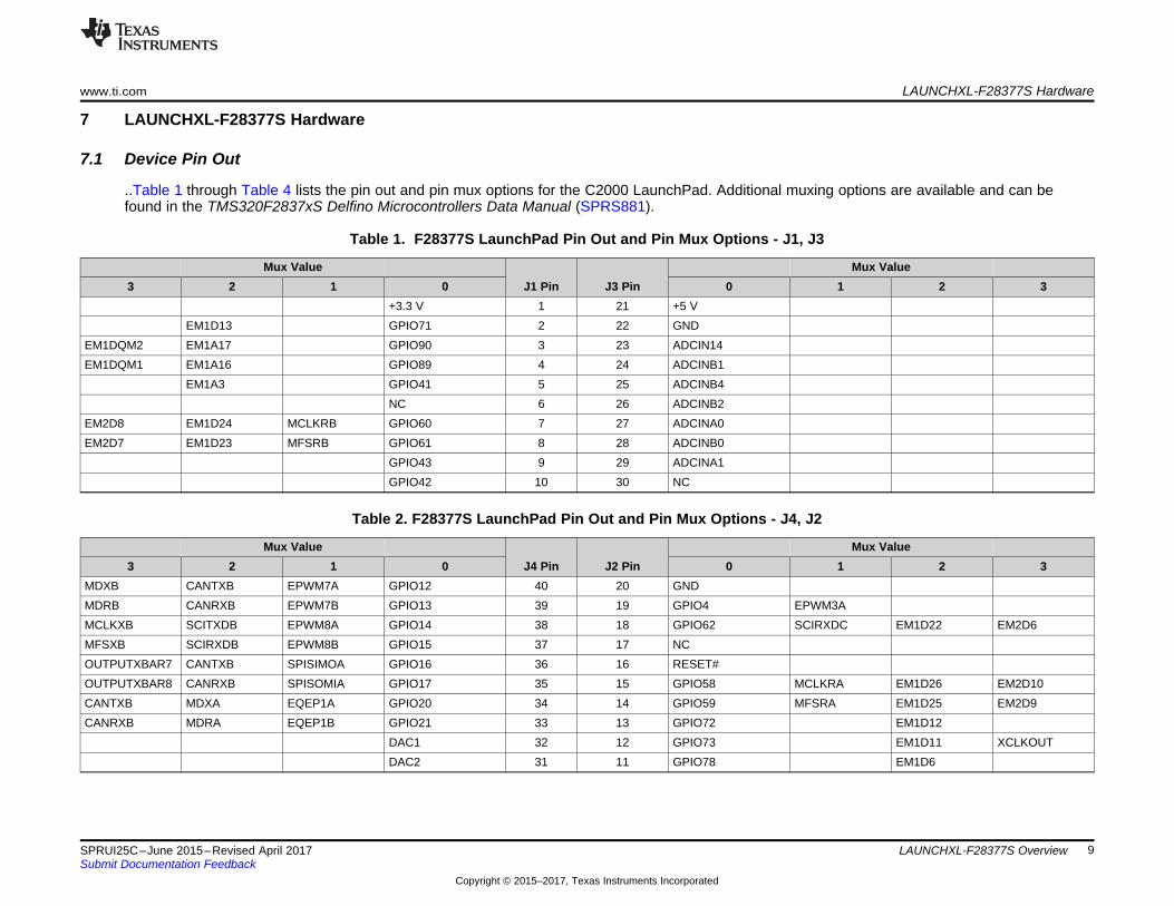
..Table 1 through Table 4 lists the pin out and pin mux options for the C2000 LaunchPad. Additional muxing options are available and can befound in the TMS320F2837xS Delfino Microcontrollers Data Manual (SPRS881).
Table 1. F28377S LaunchPad Pin Out and Pin Mux Options - J1, J3
Mux ValueJ1 Pin J3 Pin
Mux Value3 2 1 0 0 1 2 3
+3.3 V 1 21 +5 VEM1D13 GPIO71 2 22 GND
EM1DQM2 EM1A17 GPIO90 3 23 ADCIN14EM1DQM1 EM1A16 GPIO89 4 24 ADCINB1
EM1A3 GPIO41 5 25 ADCINB4NC 6 26 ADCINB2
EM2D8 EM1D24 MCLKRB GPIO60 7 27 ADCINA0EM2D7 EM1D23 MFSRB GPIO61 8 28 ADCINB0
GPIO43 9 29 ADCINA1GPIO42 10 30 NC
Table 2. F28377S LaunchPad Pin Out and Pin Mux Options - J4, J2
Mux ValueJ4 Pin J2 Pin
Mux Value3 2 1 0 0 1 2 3
MDXB CANTXB EPWM7A GPIO12 40 20 GNDMDRB CANRXB EPWM7B GPIO13 39 19 GPIO4 EPWM3AMCLKXB SCITXDB EPWM8A GPIO14 38 18 GPIO62 SCIRXDC EM1D22 EM2D6MFSXB SCIRXDB EPWM8B GPIO15 37 17 NCOUTPUTXBAR7 CANTXB SPISIMOA GPIO16 36 16 RESET#OUTPUTXBAR8 CANRXB SPISOMIA GPIO17 35 15 GPIO58 MCLKRA EM1D26 EM2D10CANTXB MDXA EQEP1A GPIO20 34 14 GPIO59 MFSRA EM1D25 EM2D9CANRXB MDRA EQEP1B GPIO21 33 13 GPIO72 EM1D12
DAC1 32 12 GPIO73 EM1D11 XCLKOUTDAC2 31 11 GPIO78 EM1D6

LAUNCHXL-F28377S Hardware www.ti.com
10 SPRUI25C–June 2015–Revised April 2017Submit Documentation Feedback
Copyright © 2015–2017, Texas Instruments Incorporated
LAUNCHXL-F28377S Overview
Table 3. F28377S LaunchPad Pin Out and Pin Mux Options - J5, J7
Mux ValueJ5 Pin J7 Pin
Mux Value3 2 1 0 0 1 2 3
+3.3V 41 61 +5VNC 42 62 GND
EM1RAS EM1A14 GPIO87 43 63 ADCIN15EM1CAS EM1A13 GPIO86 44 64 ADCINA2
NC 45 65 ADCINA5NC 46 66 ADCINB5
EM1D19 GPIO65 47 67 ADCINA3NC 48 68 ADCINB3
EM1D15 GPIO69 49 69 ADCINA4EM1D18 GPIO66 50 70 NC
Table 4. F28377S LaunchPad Pin Out and Pin Mux Options - J8, J6
Mux ValueJ8 Pin J6 Pin
Mux Value3 2 1 0 0 1 2 3
EPWM2A GPIO2 80 60 GNDEPWM2B GPIO3 79 59 GPIO91 EM1A18 EEM1DQM3
ADCSOCB0 CANRXB EPWM6A GPIO10 78 58 NCOUTPUTXBAR7 SCIRXDB EPWM6B GPIO11 77 57 NCCANRXA SCITXDB SPICLKA GPIO18 76 56 RESET#CANTXA SCIRXDB SPISTEA GPIO19 75 55 GPIO63 SCITXDC EM1D21 EM2D5
NC 74 54 GPIO64 EM1D20 EM2D4NC 73 53 GPIO99 EM2A1DAC3 72 52 GPIO92 EM1A19 EM1BA1DAC4 71 51 NC
1.1
BLO
CK
DIA
GR
AM
Sh
eet
2
Sh
eet
3
Sh
eet
4 &
5
Sh
eet
2
Sh
eet
6
Sh
eet
6
Sh
eet
6
Sh
ee
t6
Sh
eet
5
RE
VD
ATA
NO
TE
RE
V1.0
20
15
03
26
OR
IGIN
AL
RE
LE
AS
ED
Po
we
r m
an
ag
em
en
t
Mic
ro U
SB
typ
e B
FT
223
2H
TM
S3
20
F2
837
7S
Bo
oste
rPa
ck 1
Co
nne
cto
r
LE
DS
CA
N
SE
RIA
L1&
2
Bo
oste
rPa
ck
2 C
onn
ecto
r
QE
PC
on
ne
cto
r
A B C D E
A B C D E
12
34
56
Date
:6
/22
/20
15
9:2
1:5
7A
MS
hee
t:1
/6RE
V:
TIT
LE
:
Docu
men
tN
um
ber:
LA
UN
CH
XL-F
283
77
S
Note
:D
NP
=D
oN
ot P
opu
late
www.ti.com LAUNCHXL-F28377S Hardware
11SPRUI25C–June 2015–Revised April 2017Submit Documentation Feedback
Copyright © 2015–2017, Texas Instruments Incorporated
LAUNCHXL-F28377S Overview
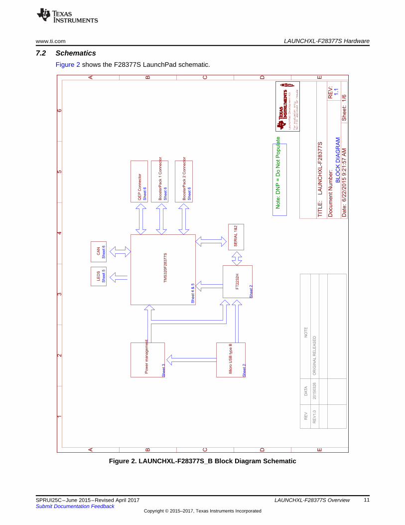
7.2 SchematicsFigure 2 shows the F28377S LaunchPad schematic.
Figure 2. LAUNCHXL-F28377S_B Block Diagram Schematic
1.1
XD
S1
00
v2
Vou
t=
3.3
VIo
ut =
1A
CD
RH
2D
18
/HP
NP
-2R
2N
C
2.2
k3.3
u
0.1
u
93LC
56B
T-I
/OT
0.1
u0.1
u0.1
u
12k1K
ISO
7231
ISO
7240
AG
ND
AG
ND
AG
ND
AG
ND
AG
ND
AG
ND
GN
D
GN
D
1K
AG
ND
Blu
e
Red
330
330
12M
36p
36p
+3V
3
00000
0 0 00
+3V
3
AG
ND
AG
ND
AG
ND
AG
ND
4.7u
4.7u
BLM15AG601SN1D
BLM15AG601SN1D
AGND
AGND
500m
A
0R
0R
AG
ND
0.1
u
AG
ND
AG
ND
AG
ND
Green820
AG
ND
TP
S62162D
SG
R
100K
10uF
22uF
2.2
uH AGND
10K
R31C
15
C16
VC
C
GN
D
6 2
CL
K4
DO
1
DI
3
CS
5
U8
VR
EG
INP
$5
0
US
BD
MP
$7
US
BD
PP
$8
RE
FP
$6
RE
SE
T#
P$
14
OS
CI
P$
2
OS
CO
P$
3
EE
CS
P$
63
EE
CL
KP
$6
2
EE
DA
TA
P$
61
TE
ST
P$
13
AGND P$10
GND1 P$1
GND2 P$5
GND3 P$11
GND4 P$15
PW
RE
N#
P$
60
SU
SP
EN
D#
P$
36
BC
BU
S3
P$
54
BC
BU
S2
P$
53
BC
BU
S1
P$
52
BC
BU
S0
P$
48
BD
BU
S7
P$
46
BD
BU
S6
P$
45
BD
BU
S5
P$
44
BD
BU
S4
P$
43
BD
BU
S3
P$
41
BD
BU
S2
P$
40
BD
BU
S1
P$
39
BD
BU
S0
P$
38
AC
BU
S3
P$
29
AC
BU
S2
P$
28
AC
BU
S1
P$
27
AC
BU
S0
P$
26
AD
BU
S7
P$
24
AD
BU
S6
P$
23
AD
BU
S5
P$
22
AD
BU
S4
P$
21
AD
BU
S3
P$
19
AD
BU
S2
P$
18
AD
BU
S1
P$
17
AD
BU
S0
P$
16
VCCIO1P$20
VCORE2P$37VCORE1P$12
VPHYP$4
AC
BU
S4
P$
30
AC
BU
S5
P$
32
AC
BU
S6
P$
33
AC
BU
S7
P$
34
BC
BU
S4
P$
55
BC
BU
S5
P$
57
BC
BU
S6
P$
58
BC
BU
S7
P$
59
GND5 P$25
GND6 P$35
GND7 P$47
GND8 P$51
VR
EG
OU
TP
$4
9
VPLLP$9
VCORE3P$64
VCCIO2P$31
VCCIO3P$42
VCCIO4P$56
TH THU
6
FT
2232H
C14
C13
C12
R24R
22
1 2 3 4 5
VC
C1
1V
CC
21
6
GN
D1
2
GN
D1
8
GN
D2
15
GN
D2
9
INA
3
INB
4
OU
TC
5
NC
16
EN
17
EN
21
0
OU
TA
14
OU
TB
13
INC
12
NC
211
U7
VC
C1
1V
CC
21
6
GN
D1
2
GN
D1
8
GN
D2
15
GN
D2
9
INA
3
INB
4
INC
5
IND
6
NC
7E
N1
0
OU
TA
14
OU
TB
13
OU
TC
12
OU
TD
11
U5
R23
D7
D8
R26
R27
Q3 C17
C18
R21
R20
R19
R18
R16
R28
R30
R32
R251
2
JP
1 JP2 12
C10
C11
L2
L1
F1 R15
R33
TP
11
TP
12 T
P13
TP
14T
P15T
P16T
P17
C43
D4
R46
TP
30
EN
P$
3
EX_PAD P$9
FB
P$
5
GN
DP
$4
PG
P$
8P
GN
DP
$1
SW
P$
7V
INP
$2
VO
SP
$6
U17
R47
C44
C45
L7
R12D
-
D-
D+
D+
US
BV
CC
US
BV
CC
TC
KT
DI
TD
OTM
S
FT
DI_
CS
FT
DI_
CS
FT
DI_
CLK
FT
DI_
CLK
FT
DI_
DA
TA
FT
DI_
DA
TA
FT
DI_
DA
TA
FT
DI_
1V
8
PW
RE
N#
SU
SP
EN
D#
FT
DI_
3V
3F
TD
I_3V
3
FT
DI_
3V
3
FT
DI_
3V
3
FT
DI_
3V
3
FT
DI_
3V
3
FT
DI_
3V
3F
TD
I_3V
3
JTA
G_T
RS
T
GP
IO85
GP
IO84
ArrayEEPROM
A B C D E
A B C D E
12
34
56
Da
te:
6/2
2/2
015
9:2
1:5
7A
MS
he
et:
2/6R
EV
:
TIT
LE
:
Docu
men
tN
um
ber:
LA
UN
CH
XL-F
283
77
S
Min
iU
SB
LAUNCHXL-F28377S Hardware www.ti.com
12 SPRUI25C–June 2015–Revised April 2017Submit Documentation Feedback
Copyright © 2015–2017, Texas Instruments Incorporated
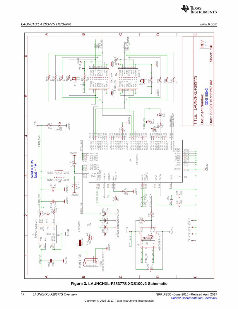
LAUNCHXL-F28377S Overview
Figure 3. LAUNCHXL-F28377S XDS100v2 Schematic
1.0
F2
83
77
SP
ow
er
Vo
ut
= 5
VIo
ut
=0
.5A
CD
RH
3D
16
/HP
NP
-3R
3N
C
2.2
u 2.2
u2.2
u 2.2
u2.2
u 2.2
u2.2
u 2.2
u2.2
u
GN
DG
ND
GN
DG
ND
GN
D
TP
S6
20
80
+3V
3 10u
GN
DG
ND
178k
64.9
k39.2
k
22u
GN
D
GN
D
220O
hm
10u
GN
D
0.1u
0.1u0.1u
0.1u
0.1u0.1u
0.1u0.1u
0.1u0.1u
0.1u0.1u
GN
DG
ND
GN
DG
ND
GN
DG
ND
220O
hm
10u
10u
10u
+3V
3
GN
DG
ND
GN
D
60O
hm
2.2
u2.2
u
+3V
3
GN
DG
ND
0.1u
0.1u
GN
D
60O
hm
2.2
u2.2
u
+3V
3
GN
DG
ND
0.1u
0.1u
GN
D
RE
F3
03
0
0.1u
2.2
u
GN
DG
ND
GN
D
OP
A320
GN
D
0.1
u
GN
D1k
1u
1u
GN
DG
ND
OP
A320
GN
D
0.1
u
GN
D
1u
GN
D
2.2
u
560m
GN
D
GN
D2.2
u
560m
820p
LM
R62421X
MF
E/N
OP
B
10K
3.3
uH
1N
5819H
W-7
-F10uF
30.1K 10K
4.7
u
+3V
3
GN
DG
ND
+5V
+3V
3
+3V
3
+3V
3
1u
C42 C46
C47 C48
C49 C75
C76 C77
C78
VIN
P$
8
EN
P$
1
MO
DE
P$
3
GN
DP
$2
*2
PG
P$
6
SW
P$
7
VO
SP
$5
FB
P$
4
U4
C79
R53
R54
R55
C80
L11
C81
C56
C57C58
C59
C60C61
C62C63
C64C65
C66C67
L5
C68
C69
C70
L3
C27
C29
C28
C30L4
C71
C72
C73
C74
IN1
OU
T2
GND 3
U1
0
C1
C2
U11
431
5 2
C5
R3
C6
C7
U13
431
5 2
C9
C19
C20
R11
C21
R52
C25
FB
3
GND 2
SD
4
SW
ITC
H1
VIN
5
U12
R14
L6
D3
C41
R17 R45
C8
L8
VD
D+
1V
2
VD
DIO
VD
DA
VD
DO
SC
+5V
VR
EF
HIA
VR
EF
HIB
A B C D E
A B C D E
12
34
56
Da
te:
6/2
2/2
01
59
:21:5
7A
MS
hee
t:3
/6RE
V:
TIT
LE
:
Do
cu
me
nt
Nu
mb
er:
LA
UN
CH
XL
-F2
83
77
S
www.ti.com LAUNCHXL-F28377S Hardware
13SPRUI25C–June 2015–Revised April 2017Submit Documentation Feedback
Copyright © 2015–2017, Texas Instruments Incorporated
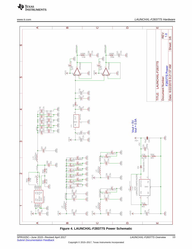
LAUNCHXL-F28377S Overview
Figure 4. LAUNCHXL-F28377S Power Schematic
1.0
F2
83
77S
_A
AD
C
GP
IO72
GP
IO84
TR
ST
10
00 0 0 0
xx
0 1 1
1 10
Em
ula
tion
Boot
Para
llel I/O
SC
IW
ait
GetM
ode
RE
SE
TB
OO
T
10MHz
36p36p
1M
2.2k
2.2k
2.2k
820
820
+3V
3+
3V
3
GN
DG
ND
GN
D
Green820
+3V
3
GN
D
204-3
ST
2.2k GN
D
GN
D
+3V
3
GN
D
0.1
u GN
D
TM
S320F
28377S
TM
S320F
28377S
GN
D
0.1u
+3V
3
GN
D
+3V
3
Q1
C4C3
R7
R6
R8
R9
R4
R5
D1
R1S
1
4561 2 3
R10
TP
18
TP
21T
P22T
P23T
P24
C39
VD
D1
6*9
VD
D3
VF
L4
1
VD
DA
18
*2
VR
EG
EN
Z6
4
VD
DIO
2*1
2
VD
DO
SC
65
*2
VS
ST
H
VS
SO
SC
67
VS
SA
17
*3
U1G
$1
XR
SN
69
X1
68
X2
66
TC
K5
0
TD
I4
6
TD
O4
7
TM
S4
9
TR
ST
N4
8
VR
EF
HIA
19
VR
EF
HIB
37
VR
EF
LO
B3
4
AD
CIN
14
/CM
PIN
4P
26
AD
CIN
15
/CM
PIN
4N
27
AD
CIN
A0
/DA
CO
UTA
25
AD
CIN
A1
/DA
CO
UT
B2
4
AD
CIN
A2
/CM
PIN
1P
23
AD
CIN
A3
/CM
PIN
1N
22
AD
CIN
A4
/CM
PIN
2P
21
AD
CIN
A5
/CM
PIN
2N
20
AD
CIN
B0
/VD
AC
28
AD
CIN
B1
/DA
CO
UT
C2
9
AD
CIN
B2
/CO
MP
IN3
P3
0
AD
CIN
B3
/CO
MP
IN3
N3
1
AD
CIN
B4
32
AD
CIN
B5
33
U1G
$2
C26
S3
12
TC
KT
DI
TD
OT
MS
TR
ST
TR
ST
RE
SE
T#
RE
SE
T#
JTA
G_T
RS
T
VD
DIO
AD
CIN
14
AD
CIN
15
AD
CIN
A0
AD
CIN
A1
AD
CIN
A2
AD
CIN
A3
AD
CIN
A4
AD
CIN
A5
AD
CIN
B0
AD
CIN
B1
AD
CIN
B2
AD
CIN
B3
AD
CIN
B4
AD
CIN
B5
GP
IO84
GP
IO72
VD
D
VD
DA
VD
DO
SC
VR
EF
HIB
VR
EF
HIA
VS
SO
SC
VS
SO
SC
1 2 3
ON
A B C D E
A B C D E
12
34
56
Da
te:
6/2
2/2
01
59
:21:5
7A
MS
hee
t:4
/6RE
V:
TIT
LE
:
Do
cu
me
nt
Nu
mb
er:
LA
UN
CH
XL
-F2
83
77
S
LAUNCHXL-F28377S Hardware www.ti.com
14 SPRUI25C–June 2015–Revised April 2017Submit Documentation Feedback
Copyright © 2015–2017, Texas Instruments Incorporated
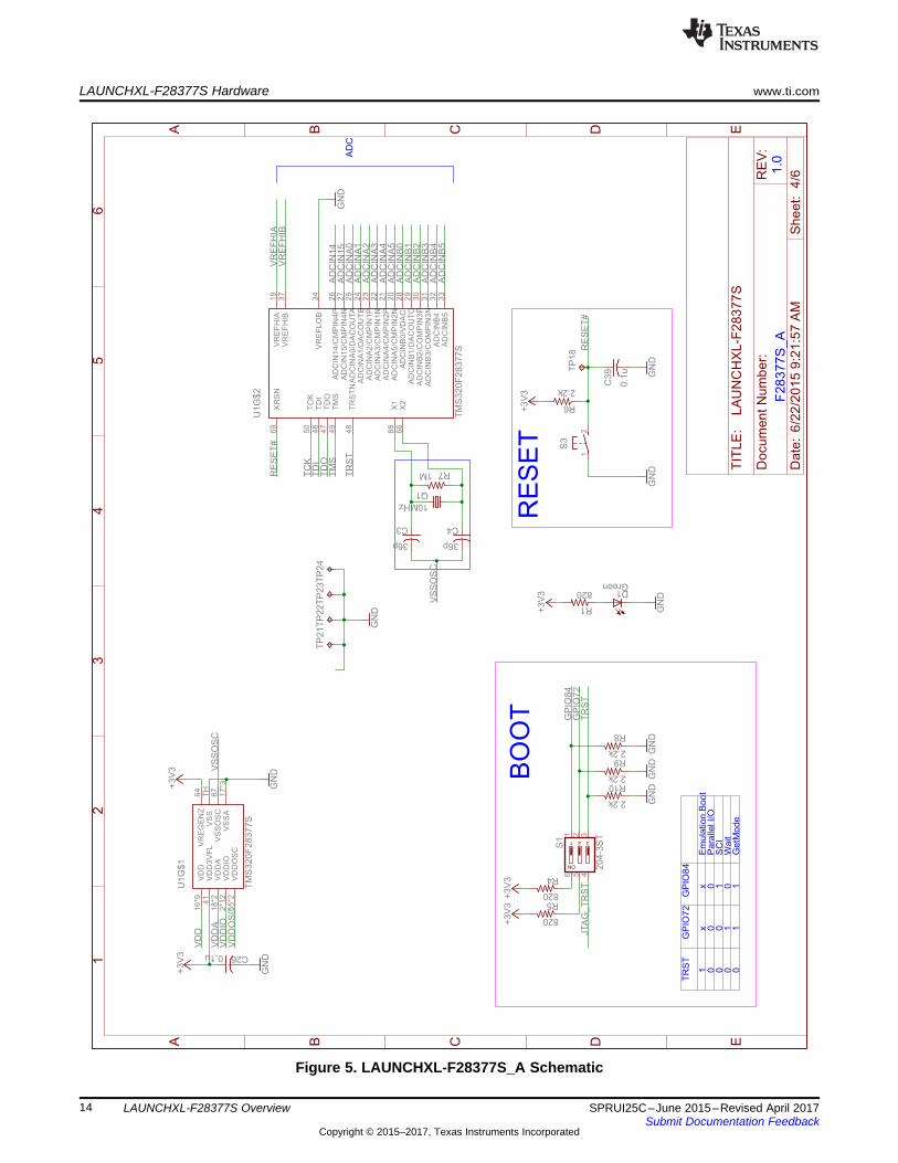
LAUNCHXL-F28377S Overview
Figure 5. LAUNCHXL-F28377S_A Schematic
1.1
F2
83
77S
_B
PW
M_D
AC
Red
Blue
SN
74LV
C2G
07
330
330
+3V
3+
3V
3+
3V
3
GN
D
1K
1K
1K
1K
0.1
u0.1
u0.1
u0.1
u
GN
DG
ND
GN
DG
ND
0.1
u
GN
D
TM
S3
20
F2
83
77
S
D9
D10
U9
1A
1
2A
32
Y4
1Y
6
VCC5 GND 2
R38
R39
R36
R37
R40
R41
C33
C34
C35
C36
C24
GP
IO2
/EP
WM
2A
/OU
TP
UT
XB
AR
1/S
DA
B9
1
GP
IO3
/EP
WM
2B
/OU
TP
UT
XB
AR
2/M
CL
KR
B/S
CL
B9
2
GP
IO4
/EP
WM
3A
/OU
TP
UT
XB
AR
3/C
AN
TX
A9
3
GP
IO1
0/E
PW
M6
A/C
AN
RX
B/A
DC
SO
CB
O/E
QE
P1
A/S
CIT
XD
B/U
PP
-WA
IT1
00
GP
IO11
/EP
WM
6B
/SC
IRX
DB
/OU
TP
UT
XB
AR
7/E
QE
P1
B/U
PP
-ST
AR
T1
GP
IO1
2/E
PW
M7
A/C
AN
TX
/MD
XB
/EQ
EP
1S
/SC
ITX
DC
/UP
P-E
NA
3
GP
IO1
3/E
PW
M7
B/C
AN
RX
B/M
DR
B/E
QE
P1
I/S
CIR
XD
C/U
PP
-D7
4
GP
IO1
4/E
PW
M8
A/S
CIT
XD
B/M
CL
KX
B/O
UT
PU
TX
BA
R3
/UP
P-D
65
GP
IO1
5/E
PW
M8
B/S
CIR
XD
B/M
FS
XB
/OU
TP
UT
XB
AR
4/U
PP
-D5
6
GP
IO1
6/S
PIS
IMO
A/C
AN
TX
B/O
UT
PU
TX
BA
R7
/EP
WM
9A
/SD
_D
1/U
PP
-D4
7
GP
IO1
7/S
PIS
OM
IA/C
AN
RX
B/O
UT
PU
TX
BA
R8
/EP
WM
9B
/SD
1_
C1
/UP
P- D
38
GP
IO1
8/S
PIC
LK
A/S
CIT
XD
B/C
AN
RX
A/E
PW
M1
0A
/SD
1_
D2
/UP
P-D
29
GP
IO1
9/S
PIS
TE
A/S
CIR
XD
B/C
AN
TX
A/E
PW
M1
0B
/SD
1_
C2
/UP
P-D
111
GP
IO2
0/E
QE
P1
A/M
DX
A/C
AN
TX
B/E
PW
M11
A/S
D1
_D
3/U
PP
-D0
12
GP
IO2
1/E
QE
P1
B/M
DR
A/C
AN
RX
B/E
PW
M11
B/S
D1
_C
3/U
PP
-CL
K1
3
GP
IO4
1/E
M1
A3
/SC
LB
51
GP
IO4
2/S
DA
A/S
CIT
XD
A/U
SB
0D
M7
3
GP
IO4
3/S
CL
A/S
CIR
XD
A/U
SB
0D
P7
4
GP
IO5
8/M
CL
KR
A/E
M1
D2
6/E
M2
D1
0/O
UT
PU
TX
BA
R1
/SP
ICL
KB
/SD
2_
D2
/SP
ISIM
OA
52
GP
IO5
9/M
FS
RA
/EM
1D
25
/EM
2D
9/O
UT
PU
TX
BA
R2
/SP
IST
EB
/SD
2_
C2
/SP
ISO
MIA
53
GP
IO6
0/M
CL
KR
B/E
M1
D2
4/E
M2
D8
/OU
TP
UT
XB
AR
3/S
PIS
IMO
B/S
D2
_D
3/S
PIC
LK
A5
4
GP
IO6
1/M
FS
RB
/EM
1D
23
/DM
2D
7/O
UT
PU
TX
BA
R4
/SP
ISO
MIB
/SD
2_
C3
/SP
IST
EA
56
GP
IO6
2/S
CIR
XD
B/E
M1
D2
2/E
M2
D6
/EQ
EP
3A
/CA
NR
XA
/SD
2_
D4
57
GP
IO6
3/S
CIT
XD
C/E
M1
D2
1/E
M2
D5
/EQ
EP
3B
/CA
NT
XA
/SD
2_
C4
/SP
ISIM
OB
58
GP
IO6
4/E
M1
D2
0/E
M2
D4
/EQ
EP
3S
/SC
IRX
DA
/SP
ISO
MIB5
9
GP
IO6
5/E
M1
D1
9/E
M2
D3
/EQ
EP
3I/
SC
ITX
DA
/SP
ICL
KB60
GP
IO6
6/E
M1
D1
8/E
M2
D2
/SD
AB
/SP
IST
EB6
1
GP
IO6
9/E
M1
D1
5/S
CL
KB
/SP
ISIM
OC
75
GP
IO7
0/E
M1
D1
4/C
AN
RX
A/S
CIT
XD
B/S
PIS
OM
IC7
6
GP
IO7
1/E
M1
D1
3/C
AN
TX
A/S
CIR
XD
B/S
PIC
LK
C77
GP
IO7
2/E
M1
D1
2/C
AN
TX
B/S
CIT
XD
C/S
PIS
TE
C80
GP
IO7
3/E
M1
D11
/XC
LK
OU
T/C
AN
RX
B/S
CIR
XD
C81
GP
IO7
8/E
M1
D6
/EQ
EP
2A
82
GP
IO8
4/S
CIT
XD
A/M
DX
B/M
DX
A8
5
GP
IO8
5/E
M1
D0
/SC
IRX
DA
/MD
RB
/MD
RA
86
GP
IO8
6/E
M1
A1
3/E
M1
CA
S/S
CIT
XD
B/M
CL
KX
B/M
CL
KX
A87
GP
IO8
7/E
M1
A1
4/E
M1
RA
S/S
CIR
XD
B/M
FS
XB
/MF
SX
A88
GP
IO8
9/E
M1
A1
6/E
M1
DQ
M1
/SC
ITX
DC
96
GP
IO9
0/E
M1
A1
7/E
M1
DQ
M2
/SC
IRX
DC
97
GP
IO9
1/E
M1
A1
8/E
M1
DQ
M3
/SD
AA
98
GP
IO9
2/E
M1
A1
9/E
M1
BA
1/S
CL
A9
9
GP
IO9
9/E
M2
A1
/EQ
EP
1I
14
U1
G$
3
GP
IO17
GP
IO16
GP
IO2
GP
IO3
GP
IO4
GP
IO12
GP
IO12
GP
IO13
GP
IO13
GP
IO14
GP
IO10
GP
IO11
GP
IO41
GP
IO42
GP
IO43
GP
IO20
GP
IO20
GP
IO21
GP
IO21
GP
IO58
GP
IO15
DA
C1
DA
C2
DA
C3
DA
C4
GP
IO18
GP
IO18
GP
IO19
GP
IO19
GP
IO59
GP
IO60
GP
IO61
GP
IO62
GP
IO63
GP
IO64
GP
IO65
GP
IO66
GP
IO69
GP
IO70
GP
IO71
GP
IO72
GP
IO73
GP
IO78
GP
IO84
GP
IO85
GP
IO86
GP
IO87
GP
IO89
GP
IO90
GP
IO91
GP
IO92
GP
IO99
A B C D E
A B C D E
12
34
56
Da
te:
6/2
2/2
01
59
:21:5
7A
MS
hee
t:5
/6RE
V:
TIT
LE
:
Do
cu
me
nt
Nu
mb
er:
LA
UN
CH
XL
-F2
83
77
S
www.ti.com LAUNCHXL-F28377S Hardware
15SPRUI25C–June 2015–Revised April 2017Submit Documentation Feedback
Copyright © 2015–2017, Texas Instruments Incorporated
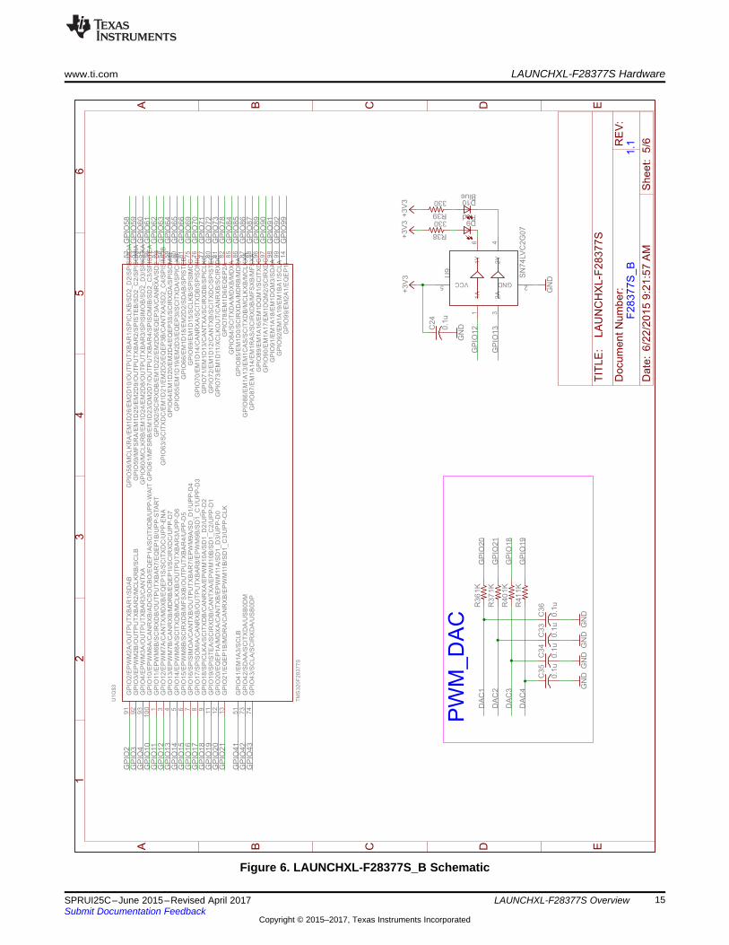
LAUNCHXL-F28377S Overview
Figure 6. LAUNCHXL-F28377S_B Schematic
1.1
Boo
ste
rPa
ck
He
ade
rs
A B I GN
DP
WR
CA
N
LE
VE
LS
HIF
T
+3V
3
GN
D
GN
D
+5V
GN
D
GN
D
+3V3
+5V
TX
B0106P
WR
+5V
+5V
GN
DG
ND
+5V
+3V
3
2.2
k
GND
120
10K 10K
0R 0R
+3V
3
GN
DG
ND
0.1u
GN
D
0.1u
GN
D
0.1u
GN
D
GN
D
+3V
3
PG
ND
1K
1K
1K
0.001u
0.001u
0.001u
1K
1K
1K
0.001u
0.001u
0.001u
HE
AD
ER
1X
03
12
JP
4
12
JP
5
A1
P$
1
A2
P$
3
A3
P$
4
A4
P$
5
A5
P$
6
A6
P$
7
B1
P$
16
B2
P$
14
B3
P$
13
B4
P$
12
B5
P$
11
B6
P$
10
GN
DP
$9
OE
P$
8
VC
CA
P$
2V
CC
BP
$1
5
U2
1 2 3 4 5
QE
P_A
1 2 3 4 5
QE
P_B
R2
CA
NH
P$
7
CA
NL
P$
6D
P$
1
EN
P$
5
GND P$2
RP
$4
RS
P$
8
VCCP$3
U3
SN
65H
VD
234D
R34
1 2 3
J12
R35
R42
R43
R44
C31
C32
C37
R13
R29
R48
C50
C51
C52
R49
R50
R51
C53
C54
C55
11
22
33
44
55
66
77
88
99
10
10
11
11
12
12
13
13
14
14
15
15
16
16
17
17
18
18
19
19
20
20
21
21
22
22
23
23
24
24
25
25
26
26
27
27
28
28
29
29
30
30
31
31
32
32
33
33
34
34
35
35
36
36
37
37
38
38
39
39
40
40
41
41
42
42
43
43
44
44
45
45
46
46
47
47
48
48
49
49
50
50
51
51
52
52
53
53
54
54
55
55
56
56
57
57
58
58
59
59
60
60
61
61
62
62
63
63
64
64
65
65
66
66
67
67
68
68
69
69
70
70
71
71
72
72
73
73
74
74
75
75
76
76
77
77
78
78
79
79
80
80
1 2 3
J10
RE
SE
T#
RE
SE
T#
GP
IO12
GP
IO42
GP
IO4
GP
IO17
GP
IO2
GP
IO3
GP
IO71
GP
IO71
AD
CIN
A4
AD
CIN
B2
AD
CIN
B4
GP
IO43
AD
CIN
A1
AD
CIN
B1
AD
CIN
A3
AD
CIN
A0
AD
CIN
B3
AD
CIN
15
AD
CIN
A5
AD
CIN
B0
GP
IO61
GP
IO13
GP
IO13
AD
CIN
B5
GP
IO14
GP
IO63
GP
IO63
GP
IO91
GP
IO64
GP
IO99
GP
IO10
GP
IO10
GP
IO11
GP
IO11
GP
IO72
GP
IO73
GP
IO62
GP
IO62
GP
IO20
GP
IO21
EQ
EP
1A
EQ
EP
1A
EQ
EP
1B
EQ
EP
1B
EQ
EP
1I
EQ
EP
1I
EQ
EP
2A
EQ
EP
2A
EQ
EP
2B
EQ
EP
2B
EQ
EP
2I
EQ
EP
2I
DA
C1
DA
C2
DA
C3
DA
C4
GP
IO70
CA
NH
CA
NL
AD
CIN
14
GP
IO87
GP
IO86
GP
IO41
GP
IO60
GP
IO58
GP
IO59
GP
IO78
GP
IO15
GP
IO16
GP
IO89
GP
IO65
GP
IO65
GP
IO90
GP
IO69
GP
IO66
AD
CIN
A2
GP
IO18
GP
IO19
GP
IO92
A B C D E
A B C D E
12
34
56
Date
:6
/22
/20
15
9:2
1:5
7A
MS
he
et:
6/6R
EV
:
TIT
LE
:
Do
cu
men
tN
um
be
r:
LA
UN
CH
XL-F
28
377
S
+3V
3G
ND
GN
D
LAUNCHXL-F28377S Hardware www.ti.com
16 SPRUI25C–June 2015–Revised April 2017Submit Documentation Feedback
Copyright © 2015–2017, Texas Instruments Incorporated
LAUNCHXL-F28377S Overview
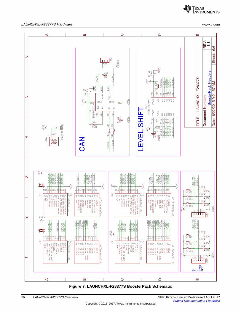
Figure 7. LAUNCHXL-F28377S BoosterPack Schematic

www.ti.com LAUNCHXL-F28377S Hardware
17SPRUI25C–June 2015–Revised April 2017Submit Documentation Feedback
Copyright © 2015–2017, Texas Instruments Incorporated
LAUNCHXL-F28377S Overview
7.3 PCB LayoutFigure 8 through Figure 13 shows the LAUNCHXL-F28377S PCB layout.
Figure 8. Top Silk Figure 9. Top Copper
Figure 10. Inner Copper 1 Figure 11. Inner Copper 2
Figure 12. Bottom Silk Figure 13. Bottom Copper

LAUNCHXL-F28377S Hardware www.ti.com
18 SPRUI25C–June 2015–Revised April 2017Submit Documentation Feedback
Copyright © 2015–2017, Texas Instruments Incorporated
LAUNCHXL-F28377S Overview
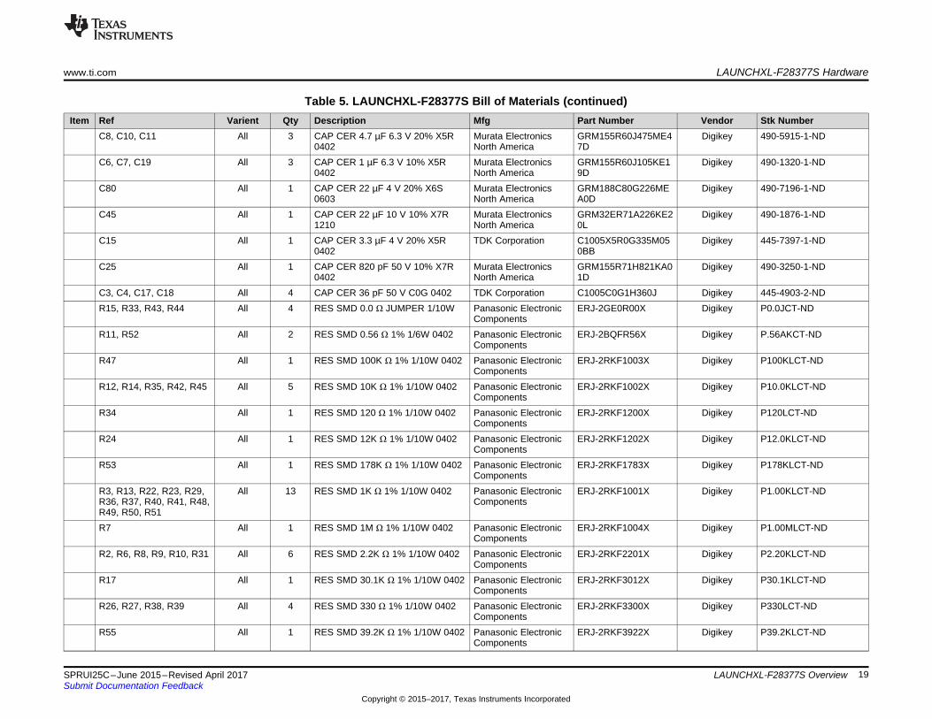
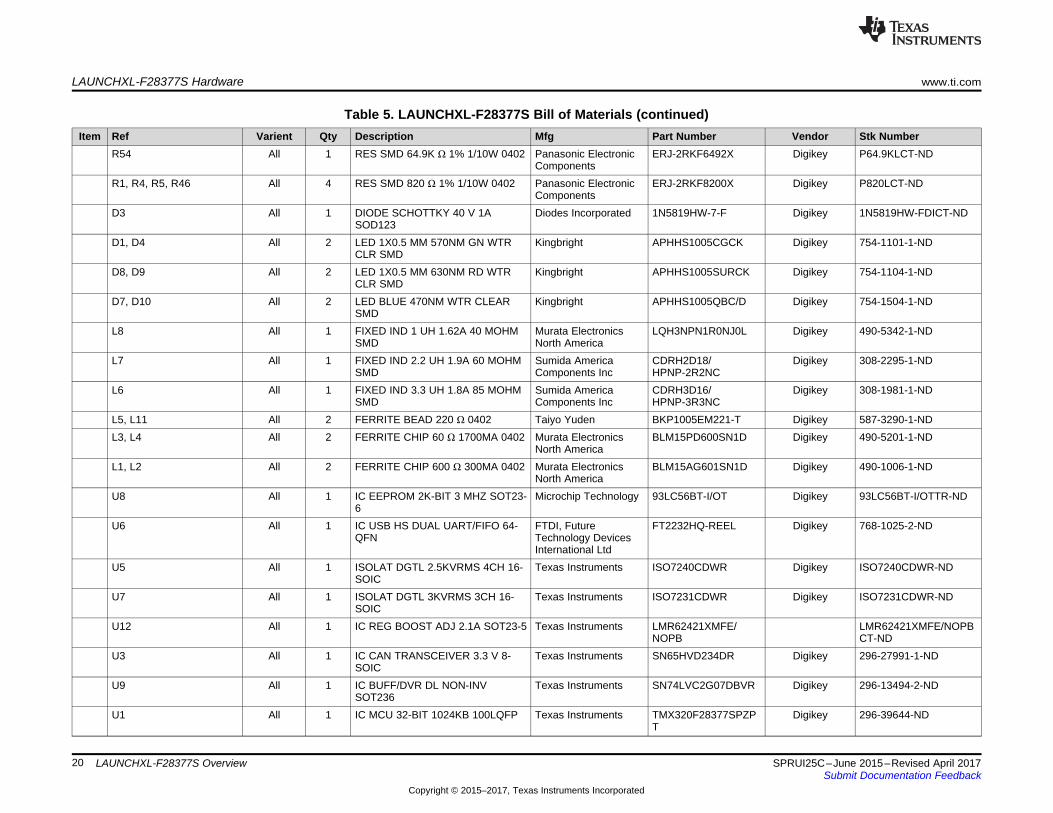
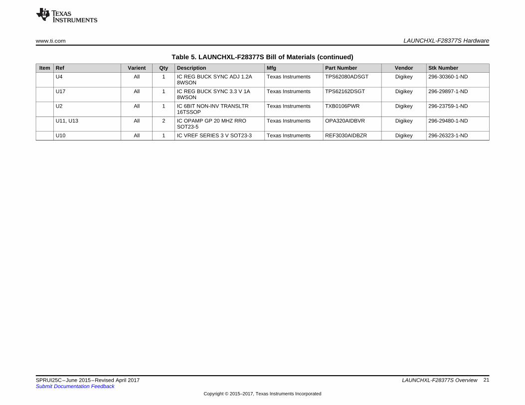
7.4 Bill of Materials (BOM)Table 5 lists the LAUNCHXL-F28377S bill of materials.
Table 5. LAUNCHXL-F28377S Bill of Materials
Item Ref Varient Qty Description Mfg Part Number Vendor Stk NumberS3 All 1 SWITCH TACTILE SPST-NO 0.05A
24 VOmron Electronics Inc-EMC Div
B3F-3152 Digikey SW410-ND
S1 All 1 SWITCH TAPE SEAL 3 POS SMD50 V
CTSElectrocomponents
219-3MST Digikey CT2193MST-ND
F1 All 1 PTC RESETTABLE .50A 15 V 1812 Bourns Inc. MF-MSMF050-2 Digikey MF-MSMF050-2TR-NDQ1 All 1 Crystal 10.0000MHz 30ppm 18 pF
60 Ω -40°C - 85°C Through HoleHC49/US
CTS-FrequencyControls
ATS100B-E Digikey CTX919-ND
Q3 All 1 CRYSTAL 12.0000 MHZ 18 pFSMD
Abracon Corporation ABLS2-12.000MHZ-D4Y-T
Digikey 535-9869-2-ND
JP1, JP2, JP4, JP5 All 4 CONN HEADER 2 POS 2.54 Wurth Electronics Inc 61300211121 Digikey 732-5315-NDJP1, JP2, JP4, JP5 All 4 SHUNT JUMPER .1" BLACK GOLD 3M 969102-0000-DA Digikey 3M9580-NDJ12, J10 All 2 CONN HEADER 3 POS 2.54 Wurth Electronics Inc 61300311121 Digikey 732-5316-NDQEP_A, QEP_B All 2 CONN HEADER 5 POS 2.54 Wurth Electronics Inc 61300511121 Digikey 732-5318-NDJ1, J2, J3, J4, J5, J6, J7,J8
All 4 LaunchPad Headers Major LeagueElectronics
SSHQ-110-D-08-G-LF Major LeagueElectronics
SSHQ-110-D-08-G-LF
R16, R18, R19, R20, R21,R25, R28, R30, R32
DNP 9 RES 0.0 Ω 1/4W 1206 SMD Panasonic - ECG ERJ-8GEY0R00V Digikey P0.0ETR-ND
CON1 All 1 CONN RECEPT MINI-USB TYPE BSMT
Mill-MaxManufacturing Corp.
897-43-005-00-100001 Digikey ED90341TR-ND
C50, C51, C52, C53, C54,C55
All 6 CAP CER 1000 pF 50 V 10% X7R0402
Murata ElectronicsNorth America
GRM155R71H102KA01D
Digikey 490-1303-1-ND
C1, C5, C9, C12, C13,C14, C16, C24, C26, C28,C30, C31, C32, C33, C34,C35, C36, C37, C39, C43,C56, C57, C58, C59, C60,C61, C62, C63, C64, C65,C66, C67, C73, C74
All 34 CAP CER 0.1 µF 10 V 10% X5R0402
Murata ElectronicsNorth America
GRM155R61A104KA01D
Digikey 490-1318-1-ND
C68, C69, C70, C79, C81 All 5 CAP CER 10 µF 4 V 20% X6S0603
Murata ElectronicsNorth America
GRM188C80G106ME47D
Digikey 490-10470-1-ND
C41, C44 All 2 CAP CER 10 µF 25 V Y5V 1210 Murata ElectronicsNorth America
GRM32NF51E106ZA01L
Digikey 490-1893-1-ND
C2, C20, C21, C27, C29,C42, C46, C47, C48, C49,C71, C72, C75, C76, C77,C78
All 16 CAP CER 2.2 µF 4 V 20% X5R0402
Murata ElectronicsNorth America
GRM155R60G225ME15D
Digikey 490-4518-1-ND
www.ti.com LAUNCHXL-F28377S Hardware
19SPRUI25C–June 2015–Revised April 2017Submit Documentation Feedback
Copyright © 2015–2017, Texas Instruments Incorporated
LAUNCHXL-F28377S Overview
Table 5. LAUNCHXL-F28377S Bill of Materials (continued)Item Ref Varient Qty Description Mfg Part Number Vendor Stk Number
C8, C10, C11 All 3 CAP CER 4.7 µF 6.3 V 20% X5R0402
Murata ElectronicsNorth America
GRM155R60J475ME47D
Digikey 490-5915-1-ND
C6, C7, C19 All 3 CAP CER 1 µF 6.3 V 10% X5R0402
Murata ElectronicsNorth America
GRM155R60J105KE19D
Digikey 490-1320-1-ND
C80 All 1 CAP CER 22 µF 4 V 20% X6S0603
Murata ElectronicsNorth America
GRM188C80G226MEA0D
Digikey 490-7196-1-ND
C45 All 1 CAP CER 22 µF 10 V 10% X7R1210
Murata ElectronicsNorth America
GRM32ER71A226KE20L
Digikey 490-1876-1-ND
C15 All 1 CAP CER 3.3 µF 4 V 20% X5R0402
TDK Corporation C1005X5R0G335M050BB
Digikey 445-7397-1-ND
C25 All 1 CAP CER 820 pF 50 V 10% X7R0402
Murata ElectronicsNorth America
GRM155R71H821KA01D
Digikey 490-3250-1-ND
C3, C4, C17, C18 All 4 CAP CER 36 pF 50 V C0G 0402 TDK Corporation C1005C0G1H360J Digikey 445-4903-2-NDR15, R33, R43, R44 All 4 RES SMD 0.0 Ω JUMPER 1/10W Panasonic Electronic
ComponentsERJ-2GE0R00X Digikey P0.0JCT-ND
R11, R52 All 2 RES SMD 0.56 Ω 1% 1/6W 0402 Panasonic ElectronicComponents
ERJ-2BQFR56X Digikey P.56AKCT-ND
R47 All 1 RES SMD 100K Ω 1% 1/10W 0402 Panasonic ElectronicComponents
ERJ-2RKF1003X Digikey P100KLCT-ND
R12, R14, R35, R42, R45 All 5 RES SMD 10K Ω 1% 1/10W 0402 Panasonic ElectronicComponents
ERJ-2RKF1002X Digikey P10.0KLCT-ND
R34 All 1 RES SMD 120 Ω 1% 1/10W 0402 Panasonic ElectronicComponents
ERJ-2RKF1200X Digikey P120LCT-ND
R24 All 1 RES SMD 12K Ω 1% 1/10W 0402 Panasonic ElectronicComponents
ERJ-2RKF1202X Digikey P12.0KLCT-ND
R53 All 1 RES SMD 178K Ω 1% 1/10W 0402 Panasonic ElectronicComponents
ERJ-2RKF1783X Digikey P178KLCT-ND
R3, R13, R22, R23, R29,R36, R37, R40, R41, R48,R49, R50, R51
All 13 RES SMD 1K Ω 1% 1/10W 0402 Panasonic ElectronicComponents
ERJ-2RKF1001X Digikey P1.00KLCT-ND
R7 All 1 RES SMD 1M Ω 1% 1/10W 0402 Panasonic ElectronicComponents
ERJ-2RKF1004X Digikey P1.00MLCT-ND
R2, R6, R8, R9, R10, R31 All 6 RES SMD 2.2K Ω 1% 1/10W 0402 Panasonic ElectronicComponents
ERJ-2RKF2201X Digikey P2.20KLCT-ND
R17 All 1 RES SMD 30.1K Ω 1% 1/10W 0402 Panasonic ElectronicComponents
ERJ-2RKF3012X Digikey P30.1KLCT-ND
R26, R27, R38, R39 All 4 RES SMD 330 Ω 1% 1/10W 0402 Panasonic ElectronicComponents
ERJ-2RKF3300X Digikey P330LCT-ND
R55 All 1 RES SMD 39.2K Ω 1% 1/10W 0402 Panasonic ElectronicComponents
ERJ-2RKF3922X Digikey P39.2KLCT-ND
LAUNCHXL-F28377S Hardware www.ti.com
20 SPRUI25C–June 2015–Revised April 2017Submit Documentation Feedback
Copyright © 2015–2017, Texas Instruments Incorporated
LAUNCHXL-F28377S Overview
Table 5. LAUNCHXL-F28377S Bill of Materials (continued)Item Ref Varient Qty Description Mfg Part Number Vendor Stk Number
R54 All 1 RES SMD 64.9K Ω 1% 1/10W 0402 Panasonic ElectronicComponents
ERJ-2RKF6492X Digikey P64.9KLCT-ND
R1, R4, R5, R46 All 4 RES SMD 820 Ω 1% 1/10W 0402 Panasonic ElectronicComponents
ERJ-2RKF8200X Digikey P820LCT-ND
D3 All 1 DIODE SCHOTTKY 40 V 1ASOD123
Diodes Incorporated 1N5819HW-7-F Digikey 1N5819HW-FDICT-ND
D1, D4 All 2 LED 1X0.5 MM 570NM GN WTRCLR SMD
Kingbright APHHS1005CGCK Digikey 754-1101-1-ND
D8, D9 All 2 LED 1X0.5 MM 630NM RD WTRCLR SMD
Kingbright APHHS1005SURCK Digikey 754-1104-1-ND
D7, D10 All 2 LED BLUE 470NM WTR CLEARSMD
Kingbright APHHS1005QBC/D Digikey 754-1504-1-ND
L8 All 1 FIXED IND 1 UH 1.62A 40 MOHMSMD
Murata ElectronicsNorth America
LQH3NPN1R0NJ0L Digikey 490-5342-1-ND
L7 All 1 FIXED IND 2.2 UH 1.9A 60 MOHMSMD
Sumida AmericaComponents Inc
CDRH2D18/HPNP-2R2NC
Digikey 308-2295-1-ND
L6 All 1 FIXED IND 3.3 UH 1.8A 85 MOHMSMD
Sumida AmericaComponents Inc
CDRH3D16/HPNP-3R3NC
Digikey 308-1981-1-ND
L5, L11 All 2 FERRITE BEAD 220 Ω 0402 Taiyo Yuden BKP1005EM221-T Digikey 587-3290-1-NDL3, L4 All 2 FERRITE CHIP 60 Ω 1700MA 0402 Murata Electronics
North AmericaBLM15PD600SN1D Digikey 490-5201-1-ND
L1, L2 All 2 FERRITE CHIP 600 Ω 300MA 0402 Murata ElectronicsNorth America
BLM15AG601SN1D Digikey 490-1006-1-ND
U8 All 1 IC EEPROM 2K-BIT 3 MHZ SOT23-6
Microchip Technology 93LC56BT-I/OT Digikey 93LC56BT-I/OTTR-ND
U6 All 1 IC USB HS DUAL UART/FIFO 64-QFN
FTDI, FutureTechnology DevicesInternational Ltd
FT2232HQ-REEL Digikey 768-1025-2-ND
U5 All 1 ISOLAT DGTL 2.5KVRMS 4CH 16-SOIC
Texas Instruments ISO7240CDWR Digikey ISO7240CDWR-ND
U7 All 1 ISOLAT DGTL 3KVRMS 3CH 16-SOIC
Texas Instruments ISO7231CDWR Digikey ISO7231CDWR-ND
U12 All 1 IC REG BOOST ADJ 2.1A SOT23-5 Texas Instruments LMR62421XMFE/NOPB
LMR62421XMFE/NOPBCT-ND
U3 All 1 IC CAN TRANSCEIVER 3.3 V 8-SOIC
Texas Instruments SN65HVD234DR Digikey 296-27991-1-ND
U9 All 1 IC BUFF/DVR DL NON-INVSOT236
Texas Instruments SN74LVC2G07DBVR Digikey 296-13494-2-ND
U1 All 1 IC MCU 32-BIT 1024KB 100LQFP Texas Instruments TMX320F28377SPZPT
Digikey 296-39644-ND
www.ti.com LAUNCHXL-F28377S Hardware
21SPRUI25C–June 2015–Revised April 2017Submit Documentation Feedback
Copyright © 2015–2017, Texas Instruments Incorporated
LAUNCHXL-F28377S Overview
Table 5. LAUNCHXL-F28377S Bill of Materials (continued)Item Ref Varient Qty Description Mfg Part Number Vendor Stk Number
U4 All 1 IC REG BUCK SYNC ADJ 1.2A8WSON
Texas Instruments TPS62080ADSGT Digikey 296-30360-1-ND
U17 All 1 IC REG BUCK SYNC 3.3 V 1A8WSON
Texas Instruments TPS62162DSGT Digikey 296-29897-1-ND
U2 All 1 IC 6BIT NON-INV TRANSLTR16TSSOP
Texas Instruments TXB0106PWR Digikey 296-23759-1-ND
U11, U13 All 2 IC OPAMP GP 20 MHZ RROSOT23-5
Texas Instruments OPA320AIDBVR Digikey 296-29480-1-ND
U10 All 1 IC VREF SERIES 3 V SOT23-3 Texas Instruments REF3030AIDBZR Digikey 296-26323-1-ND
References www.ti.com
22 SPRUI25C–June 2015–Revised April 2017Submit Documentation Feedback
Copyright © 2015–2017, Texas Instruments Incorporated
LAUNCHXL-F28377S Overview
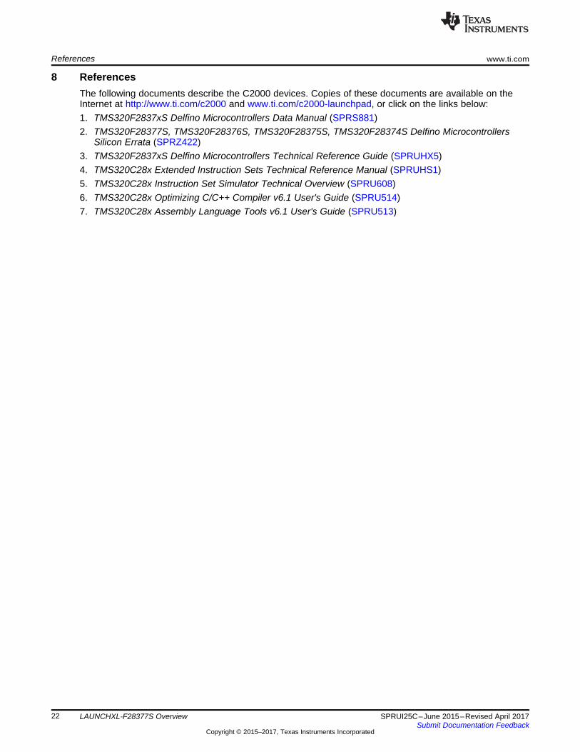
8 ReferencesThe following documents describe the C2000 devices. Copies of these documents are available on theInternet at http://www.ti.com/c2000 and www.ti.com/c2000-launchpad, or click on the links below:1. TMS320F2837xS Delfino Microcontrollers Data Manual (SPRS881)2. TMS320F28377S, TMS320F28376S, TMS320F28375S, TMS320F28374S Delfino Microcontrollers
Silicon Errata (SPRZ422)3. TMS320F2837xS Delfino Microcontrollers Technical Reference Guide (SPRUHX5)4. TMS320C28x Extended Instruction Sets Technical Reference Manual (SPRUHS1)5. TMS320C28x Instruction Set Simulator Technical Overview (SPRU608)6. TMS320C28x Optimizing C/C++ Compiler v6.1 User's Guide (SPRU514)7. TMS320C28x Assembly Language Tools v6.1 User's Guide (SPRU513)

www.ti.com Frequently Asked Questions (FAQ)
23SPRUI25C–June 2015–Revised April 2017Submit Documentation Feedback
Copyright © 2015–2017, Texas Instruments Incorporated
LAUNCHXL-F28377S Overview
9 Frequently Asked Questions (FAQ)1. Can other programming and debug tools (such as an XDS510 emulator) be used with the C2000
LaunchPad?While a user could potentially connect an external emulator to the F28377S device present on theLaunchPad, it would require some rework of the board. It is recommended that users who want to usean external emulator purchase a controlCard and docking station that includes an external JTAGconnector.
2. What versions of Code Composer Studio can be used to develop software for the C2000 LaunchPad?It is highly recommend that novice users develop applications with Code Composer Studio v6. Thedrivers, examples, and other associated software are tailored to make the user experience as smoothas possible in Code Composer Studio v6.
3. Why can’t I connect to the LaunchPad in Code Composer Studio?There are a number of things that could cause this and they all have an easy fix.• Is S1 switch 3 in the down position?
This is the TRST pin that enables and disables JTAG functionality on the chip. This switch must bein the up position for the emulator to be able to connect.
• Are both power LEDs lit?The board has two power domains because of the isolated JTAG interface. For low-voltageapplication development, JTAG isolation is not needed and the power domains can be combined toallow for convenience (that is, the board can be powered completely through the USB). Ensure thatjumpers are placed on the posts of JP1 and JP2.
• Are drivers correctly installed for the XDS100v2 present on the LaunchPad?Right click on My Computer and select properties. Navigate to the Hardware tab in the dialog boxand open the device manager. Scroll to the bottom of the list and expand the USB Serial Buscontrollers item. Are there two entries for TI XDS100 Channel A/B? If not, try unplugging andreplugging in the board. Does Windows give you any messages in the system tray? In DeviceManger, do either of the entries have a yellow exclamation mark over their icon? If so, tryreinstalling the drivers.
4. Why is the serial connection not working?• Are you using the correct COM port?
Right click on My Computer and select properties. Navigate to the Hardware tab in the dialog box andopen the device manager. Scroll to Ports (COM & LPT) and expand this entry. Is there a USB SerialPort listed? If so, read the COM number to the right of the entry; this is the COM number you shouldbe using.
• Are you using the correct baud rate?Most, if not all, of the examples are configured for a baud rate of 115200 when the CPU is running at200 MHz. If you have changed the PLL settings or written your own application you may have torecalculate the baud rate for your specific application. For information on how to do this, see theTMS320F2837xS Delfino Microcontrollers Technical Reference Guide (SPRUHX5).
Revision History www.ti.com
24 SPRUI25C–June 2015–Revised April 2017Submit Documentation Feedback
Copyright © 2015–2017, Texas Instruments Incorporated
Revision History
Revision HistoryNOTE: Page numbers for previous revisions may differ from page numbers in the current version.
Changes from B Revision (January 2017) to C Revision ............................................................................................... Page
• Update was made to Table 1 ............................................................................................................ 9
IMPORTANT NOTICE FOR TI DESIGN INFORMATION AND RESOURCES
Texas Instruments Incorporated (‘TI”) technical, application or other design advice, services or information, including, but not limited to,reference designs and materials relating to evaluation modules, (collectively, “TI Resources”) are intended to assist designers who aredeveloping applications that incorporate TI products; by downloading, accessing or using any particular TI Resource in any way, you(individually or, if you are acting on behalf of a company, your company) agree to use it solely for this purpose and subject to the terms ofthis Notice.TI’s provision of TI Resources does not expand or otherwise alter TI’s applicable published warranties or warranty disclaimers for TIproducts, and no additional obligations or liabilities arise from TI providing such TI Resources. TI reserves the right to make corrections,enhancements, improvements and other changes to its TI Resources.You understand and agree that you remain responsible for using your independent analysis, evaluation and judgment in designing yourapplications and that you have full and exclusive responsibility to assure the safety of your applications and compliance of your applications(and of all TI products used in or for your applications) with all applicable regulations, laws and other applicable requirements. Yourepresent that, with respect to your applications, you have all the necessary expertise to create and implement safeguards that (1)anticipate dangerous consequences of failures, (2) monitor failures and their consequences, and (3) lessen the likelihood of failures thatmight cause harm and take appropriate actions. You agree that prior to using or distributing any applications that include TI products, youwill thoroughly test such applications and the functionality of such TI products as used in such applications. TI has not conducted anytesting other than that specifically described in the published documentation for a particular TI Resource.You are authorized to use, copy and modify any individual TI Resource only in connection with the development of applications that includethe TI product(s) identified in such TI Resource. NO OTHER LICENSE, EXPRESS OR IMPLIED, BY ESTOPPEL OR OTHERWISE TOANY OTHER TI INTELLECTUAL PROPERTY RIGHT, AND NO LICENSE TO ANY TECHNOLOGY OR INTELLECTUAL PROPERTYRIGHT OF TI OR ANY THIRD PARTY IS GRANTED HEREIN, including but not limited to any patent right, copyright, mask work right, orother intellectual property right relating to any combination, machine, or process in which TI products or services are used. Informationregarding or referencing third-party products or services does not constitute a license to use such products or services, or a warranty orendorsement thereof. Use of TI Resources may require a license from a third party under the patents or other intellectual property of thethird party, or a license from TI under the patents or other intellectual property of TI.TI RESOURCES ARE PROVIDED “AS IS” AND WITH ALL FAULTS. TI DISCLAIMS ALL OTHER WARRANTIES ORREPRESENTATIONS, EXPRESS OR IMPLIED, REGARDING TI RESOURCES OR USE THEREOF, INCLUDING BUT NOT LIMITED TOACCURACY OR COMPLETENESS, TITLE, ANY EPIDEMIC FAILURE WARRANTY AND ANY IMPLIED WARRANTIES OFMERCHANTABILITY, FITNESS FOR A PARTICULAR PURPOSE, AND NON-INFRINGEMENT OF ANY THIRD PARTY INTELLECTUALPROPERTY RIGHTS.TI SHALL NOT BE LIABLE FOR AND SHALL NOT DEFEND OR INDEMNIFY YOU AGAINST ANY CLAIM, INCLUDING BUT NOTLIMITED TO ANY INFRINGEMENT CLAIM THAT RELATES TO OR IS BASED ON ANY COMBINATION OF PRODUCTS EVEN IFDESCRIBED IN TI RESOURCES OR OTHERWISE. IN NO EVENT SHALL TI BE LIABLE FOR ANY ACTUAL, DIRECT, SPECIAL,COLLATERAL, INDIRECT, PUNITIVE, INCIDENTAL, CONSEQUENTIAL OR EXEMPLARY DAMAGES IN CONNECTION WITH ORARISING OUT OF TI RESOURCES OR USE THEREOF, AND REGARDLESS OF WHETHER TI HAS BEEN ADVISED OF THEPOSSIBILITY OF SUCH DAMAGES.You agree to fully indemnify TI and its representatives against any damages, costs, losses, and/or liabilities arising out of your non-compliance with the terms and provisions of this Notice.This Notice applies to TI Resources. Additional terms apply to the use and purchase of certain types of materials, TI products and services.These include; without limitation, TI’s standard terms for semiconductor products http://www.ti.com/sc/docs/stdterms.htm), evaluationmodules, and samples (http://www.ti.com/sc/docs/sampterms.htm).
Mailing Address: Texas Instruments, Post Office Box 655303, Dallas, Texas 75265Copyright © 2017, Texas Instruments Incorporated