launch set-back testing of projectile components -...
TRANSCRIPT
Launch Set-Back Testing of Projectile Components
Viggo K. Hansen ∗
University of Washington, Seattle, WA, 98195-2250
Impulsive launched satellites and hypersonic projectiles proposed for both commercialand military applications require acceleration-tolerant thermal protection systems, avion-ics, propulsion systems, and other major components. Low-cost means of testing the ac-celeration tolerance of subsystems are being developed at the University of Washingtonutilizing the 38-mm-bore light gas gun and 16-m-long test section of the ram acceleratorfacility. Pistons designed to carry a test payload are launched at the desired peak accel-eration through the 5-m-long launch tube and then softly recovered by gasdynamic meansin a 12-m-long segment of the ram accelerator test section. An experimental program onaerogel-coated stainless steel nose cones has been successfully carried out to establish thegun-launch acceleration limits of the thermal protection material and bonding techniques.Theoretical modeling of the gun launch and gasdynamic deceleration processes has beenapplied to predict the requisite fill pressure of the deceleration section to catch the pro-jectile at the desired position as a function of test section length, gas (N2 or CO2), pistonmass, velocity, breech pressure, and residual air pressure in the launch tube. Stress analysistools are used to facilitate the design of an effective piston capable of supporting diversepayloads such as Printed Circuit Boards and GPS antenna window materials during thelaunch and recovery process. The results of this experimental and theoretical researcheffort are presented.
Nomenclature
P Pressure [psi]a Acceleration [m/s2]G Acceleration of gravity [9.81m/s2]m Piston mass [kg]d Bore diameter [m]T Temperature [K]V Velocity [m/s]x Position [m]l Breech length [m]L Barrel length [m]R Specific gas constant [J · kg−1K−1]
Greek
γ Specific heat ratioχ Molecular weight [kg/kg-mol]
Subscript
i Initialavg AverageP Peakc Catcher sectionp Piston/Projectileg Gas
∗Undergraduate Research Assistant, Department of Aeronautics and Astronautics, Box 352500, AIAA Student Member.
1 of 12
American Institute of Aeronautics and Astronautics
I. Introduction
Gun launch set-back testing is critical for verifying the reliability of key components of projectiles used forhypersonic applications. Complex systems have been successfully fired from conventional artillery systemsat velocities up to 1 km/s, including laser and GPS guidance systems and in some cases even UnmannedAerial Vehicles such as the Wide Area Surveillance Projectile.1 Scramjet propulsion systems have beensuccessfully launched at velocities of approximately 3 km/s by the Lawrence Livermore National LaboratorySuper High Altitude Research Project (SHARP) gun project;2 however, the program was discontinued.3
Launching projectiles to hypersonic velocities; i.e., in excess of 2 km/s, typically requires extremely highlaunch accelerations and sophisticated avionic control systems to fulfill mission requirements for both militaryand commercial applications, as described in the following.
A. Hypersonic Projectile Development
Aeronautical systems are inherently expensive to develop and high acceleration loads heighten technical risk,as demonstrated in the tumultuous history of the Sense And Destroy ARMor (SADARM) munition program.Reliability issues plagued the program for almost two decades causing the estimated total cost of developmentto grow to significantly over a billion dollars leading to program cancellation by the House Armed ServicesCommittee in 1999.4 Some of the key subsystems which are most vulnerable to high accelerations are thoseused for thermal protection, guidance, and actuators for aerodynamic control surfaces. Of immediate interestto the Office of Naval Research (ONR) is the development of an electromagnetic (EM) railgun launch systemfor long-range tactical support applications. The mission profile requires the projectile to withstand 40,000G peak launch acceleration, aerodynamic heat loading from sea-level launch at 2.5 km/s, and be able toprecisely engage via GPS a target located 200+ km down range. All major projectile subsystems must behardened to withstand the high set-back accelerations from the EM launcher.
B. Impulsive Satellite Launch
One of the primary goals of the ram accelerator6–8 or any potentially scalable impulsive launcher (e.g.; EM-railgun,9 blast wave accelerator10 or distributed-injection light gas gun11) is to facilitate the high-volumeinexpensive launch of satellites. Payloads would be launched inside a sacrificial aero-shell through theatmosphere with a rocket motor to make up any remaining ∆V and circularize their orbits. Other proposalseliminate the rocket motor, in favor of an Orbiting Magnetic Arrest System.12 Impulsive space launchoffers the potential to completely alter the LEO communications landscape through a transition from largesatellites designed for 5-10 year operational life, produced with expensive space-rated electronics to an arrayof mass produced satellites built with commercial-off-the-shelf (COTS) components in a lower (300-800 km)LEO orbit with expected orbital/design lifetimes of less than three years.13
Acceleration hardening for multi-thousand G loads goes against traditional minimized mass satellitedesign methodology which is geared toward relatively soft rocket launches with peak accelerations less than10 G. Practical limitations on impulsive space launcher length mandate peak and average acceleration toseveral thousand G which is within the range of tolerance demonstrated by cell phone drop testing.14 Atan average acceleration 2000 G, the length of a direct space launch sytem with muzzle velocity of 6 km/swould be approximately 1 km, which is reasonable for a launcher capable of delivering 100-1000 kg payloadsto LEO.
A suitable baseline comparison is the Iridium satellite constellation, the most technically advanced com-mercial LEO constellation to date. The Iridium constellation was launched ca. 1997-1998. The individualsatellites run on seven 32-bit Motorola PowerPC 603E processors at 200 MHz. Switching to an impulsivelylaunched network could bring about order of magnitude change in satellite mass, constellation density, launchrate, and network latency analogous to the change from the PowerPC 603E desktop processor to contem-porary 64-bit embedded systems such as the 600Mhz X-scale Gumstix or 1.8 Ghz Intel Atom System on aChip(SoC) computers. Either is competitive to the processing power of the combined seven processors on the
2 of 12
American Institute of Aeronautics and Astronautics
original Iridium satellite. The lower orbits of this design combined with the high launch/replacement ratecould create a network that keeps pace with Moores Law (stating that the number of transistors per unitarea on an Integrated circuit double every 24 months), with the satellite design becoming an iterative ratherthan static process in the lifecycle of the constellation. A primary benefit of dense LEO constellations isthe increased suitability for a completely Internet Protocol (IP) network incorporating Inter-Satellite links15
(ISLs) requiring every satellite to act as a space based router.16 The Iridium constellation already uses KaBand microwave ISLs although it was not originally designed as a purely IP network.
A significant technical risk in developing impulsive launchers for this role is the tolerance of COTSelectronics to elevated acceleration levels. It should be noted that many constellation designs, includingIridium and Teledesic, originally called for lower orbits and larger constellations (Teledesic; 840 Iridium; 77)to make use of these fundamental advantages in network topology. Cost optimization dominated by launchcosts forced Iridium to scale back to 66 active satellites. In the case of Teledesic the design was scaled backto 288 active satellites at a higher 1400 km orbit in the 1997 Boeing redesign further illustrating this trendshortly before Teledesic went bankrupt. It is possible that these constellations may be reconfigured for lowerorbit operation if they adopt an impulsive launcher technology for the necessary re-launch of satellites whichare just beginning to reach the end of their useful lifetime.13
II. Acceleration Hardening Techniques
Methods for hardening electronics for gun launch suggested by Berman14 include; under-fill;i.e., placementof additional epoxy-type resin beneath IC chips around the Flip Chip and/or Ball Grid Array solder joints.Encapsulation (potting) inside epoxy-type resins or foaming materials to absorbs shocks and mechanicalenergy. One method explored by Quesenberry17 involves the use of a potting mixture of hollow and solidglass bead filler material, a relationship was found between the coefficient of thermal expansion (CTE) and theratio of hollow to solid beads. Matching the average CTE of the electronics payload to the potting compoundcould play an important role in dissipating the heat from the live electronics with minimal structural effectsallowing it to survive the temperature extremes in space. Component selection is also critical, a desirableapproach may be to do away with exposed printed circuit boards altogether since much of the complexityof electronics acceleration-hardening stem from the (often exposed) solder connections between the chip andPCB. Recent industry development of system-on-a-chip computers, a type of embedded systems whereby allthe components of a full computer (CPU, system-bus, power management etc.) are integrated into a singleIntegrated Circuit will allow even more sophisticated acceleration-tolerant capabilities for gun-launchedpayloads.
There have been several efforts to experimentally investigate the problems associated with satellite sub-system gun launch, the High altitude Research Program (HARP) in the late 1960s and later in the 1990sthe SHARP and Jules Verne Launcher (JVL) projects. These programs had the ultimate goal of deliveringa functional satellite to orbit. The HARP project developed the Martlet gun launched rocket system andtested 1960s accelerometers, cold gas ACS thrusters and solid rocket motors which survived peak accel-erations exceeding ten thousand G.18 Detailed designs for satellites launched with a JVL system and aneconomic analysis were presented in studies carried out by researchers at the John Hopkins Applied PhysicsLaboratory.11
III. Theory
This system can be theoretically modeled in two distinct sections, the helium light gas gun and dumptank section and the segment of the ram accelerator test section which is used as the catcher. The dumptank captures a major portion of the helium gas from the light gas gun to reduce or eliminate its effect onthe projectile trajectory as it enters the catcher section. Piston mass and velocity at the LGG muzzle areused as input parameters to determine an acceptable pressure in the catcher section so that the test articledoes not impact the endwall and estimate catcher set-forward acceleration.
3 of 12
American Institute of Aeronautics and Astronautics
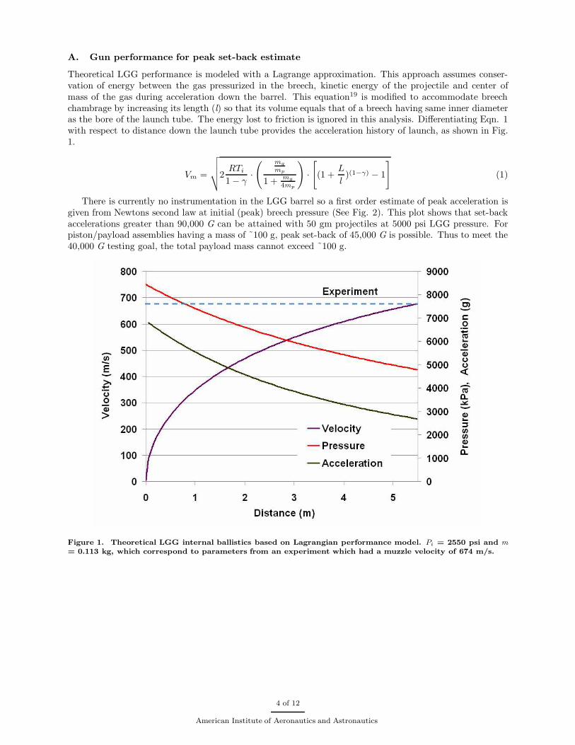
A. Gun performance for peak set-back estimate
Theoretical LGG performance is modeled with a Lagrange approximation. This approach assumes conser-vation of energy between the gas pressurized in the breech, kinetic energy of the projectile and center ofmass of the gas during acceleration down the barrel. This equation19 is modified to accommodate breechchambrage by increasing its length (l) so that its volume equals that of a breech having same inner diameteras the bore of the launch tube. The energy lost to friction is ignored in this analysis. Differentiating Eqn. 1with respect to distance down the launch tube provides the acceleration history of launch, as shown in Fig.1.
Vm =
√
√
√
√2RTi
1 − γ·
( mg
mp
1 +mg
4mp
)
·
[
(1 +L
l)(1−γ)
− 1
]
(1)
There is currently no instrumentation in the LGG barrel so a first order estimate of peak acceleration isgiven from Newtons second law at initial (peak) breech pressure (See Fig. 2). This plot shows that set-backaccelerations greater than 90,000 G can be attained with 50 gm projectiles at 5000 psi LGG pressure. Forpiston/payload assemblies having a mass of ˜100 g, peak set-back of 45,000 G is possible. Thus to meet the40,000 G testing goal, the total payload mass cannot exceed ˜100 g.
Figure 1. Theoretical LGG internal ballistics based on Lagrangian performance model. Pi = 2550 psi and m
= 0.113 kg, which correspond to parameters from an experiment which had a muzzle velocity of 674 m/s.
4 of 12
American Institute of Aeronautics and Astronautics
Figure 2. Theoretical set-back testing envelope of UW 38-mm-bore LGG apparatus.
B. Piston deceleration for peak set-forward estimate
The catching scheme is modeled with a Method of Characteristics computer code for sabot-stripping.20,21
The MOC code models only the first incident shock from the piston upon entering the pressurized catchersection ignoring the steel plate placed at the end of the system. Input parameters are V0, χavg, Pic, γ, m,
d, and T. The numerical results are used to quantify the peak set-forward deceleration of the piston as itenters the gasdynamic catcher section. Agreement with experiment was found to be very good, as will beshown in results section.
C. Catcher gas mass scaling
Energy conservation relates projectile kinetic energy at the entrance to the catcher section to the finalpressure of the compressed gas. Even though there are several shocks reflecting between the projectile andendwall, assuming an isentropic compression (Eqn. 2) process predicts the distance into the catcher tube thatthe projectile penetrates before it rebounds to be about 7% greater than observed in experiments. Modifyingthe MOC code to account for reflections from the endwall will give better predictions for penetration depth.It is important to be able to predict the penetration depth because too much gas in the catcher sectionresults in undesirable high set-forward deceleration and the inadvertent shooting of the piston back into thebreech. Since it has larger diameter than the gun bore, the backward moving projectile bounces and tumblesinside the breech which nullifies the test.
∆x = Lc ·
[
(γ − 1)mpV2
2γmgRTc
+ 1
]
−1
γ−1
(2)
D. Structural analysis by FEM
Static analysis of piston designs by finite element method (FEM) computer program (Cosmosworks22) allowfirst order estimates of its structural robustness when subjected to high acceleration loading. The von Misesstress parameter is used as a failure criterion rather than tensile yield stress to account for the influence ofmulti-dimensional stress-strain effects on complicated geometries.
5 of 12
American Institute of Aeronautics and Astronautics

IV. Experimental Facility
The 38-mm-bore UW ram accelerator facility (Figure 3) was constructed in 1985 to research the ram-jetin a tube propulsion concept invented by Hertzberg, Bruckner and Bogandoff.5 The ram accelerator requiresa pre-launcher to accelerate the projectile (resembling a ramjet-centerbody) to supersonic velocities beforeinitiating ram acceleration, a single stage light gas gun was chosen for this role. The LGG fires by openinga valve between the breech with pressure P0 and inter-diaphragm region with pressure approximately 1
2P0.This causes ∆P between the downstream aluminum diaphragm and evacuated LGG barrel to increase topoint where it ruptures. The immediate expansion of the gas from the small inter-diaphragm volume thenreduces the interdiaphragm pressure to a point that the main breech diaphragm bursts, allowing the fullmass of helium gas in the breech to expand against the projectile. The expansion of the interdiaphragmgas against the projectile just prior to release of the main charge initiates projectile motion for a somewhat’softer’ launch of fragile payloads. Modeling the details of this process is in progress.
Figure 3. UW ram accelerator experimental facility.
The ram accelerator starting process is sensitive to the back pressure on the obturator23,24 necessitatinga vented barrel section and dump tank directly before the entrance diaphragm to the instrumented ramaccelerator test section, effectively the LGG muzzle. Upon passing through the first diaphragm into thetest section containing a pressurized propellant mixture, the magnet onboard the projectile allows positiontracking25 with electromagnetic transducers placed in instrumentation ports along the tube. Secondary toposition tracking, instrumentation options include PCB piezoelectric pressure transducers and fiber opticprobes for observing flow field luminosity and spectral analysis26,27 of the combustion process. Data arecollected at a typical sampling rate of 1 MHz by 6000 and 8000 series LeCroy waveform analyzers and initiallyprocessed with the Catalyst software. The data are then exported to Matlab for discrete Fourier analysisand presentation.
The projectile traverses the test section passing through multiple stages of varying propellant mixturesoptimized for the expected projectile velocity in that stage. After exiting the ram test section the projectileexperiences 1 m of free flight in the final dump tank, where it can be photographed or flash x-rayed through theobservation windows, before striking a series of aluminum plates in the catcher tube. The facility is used fora range of experiments including basic shock tube, detonation, material impact and piston dynamics studies.Piston experiments conducted include methods of firing a thin-walled ’cup’ style piston with the LGG tohigh friction points distributed along the ram accelerator test section allowing placement of diaphragms atdesired points via gun launch.28
6 of 12
American Institute of Aeronautics and Astronautics
V. Set-Back Test Piston Design and Analysis
A. Piston Design
Figure 4. Test article support piston design.
The piston should be fully reusable to reduce test se-ries cost and withstand the peak pressure and accel-eration in the LGG with minimal translation/strainof the test sample. The test sample must be fullyseated against both ends of carrier to prevent it fromimpacting the inside of the piston during gun launchor catching. A threaded polycarbonate plug in acylindrical cavity was chosen as the most straightforward design. The piston material is impact gradepolycarbonate identical to the ram accelerator ob-turator.
B. Design Analysis
The set-back test piston design is modeled withSolidworks29 and subject to static analysis with theintegrated Cosmosworks22 FEM package. The loadconditions are 40,000 G and the projectile base ismodeled as fully restrained in all directions. Underhigh-G load a skyscraper loading effect is exhibited;i.e. loads stack based on density of material toward the front of piston. The stress distribution within thepiston is shown in Fig. 5 in terms of factor-of-safety for polycarbonate based on a yield stress of 8300 psi. Itis apparent that the most significant stress concentration occurs at the point where the sample is supportedat the rear of the piston. Means to better distribute this load to the piston base need to be incorporated toinsure survival of the piston. The yield stress properties of the test sample were not specified, thus there isno FOS information plotted.
The von Mises stress parameter distribution for this piston under 40,000 G set-back load is shown inFig. 6-top. The peak von Mises stress is 70 MPa (10,000 psi), thus the test sample and piston shouldbe fabricated of materials that have yield stresses of greater value. Iso-stress contours are shown in Fig.6-bottom at 7, 30, and 70 MPa von Mises stress parameter levels. It is apparent that the most significantstress due to set-back loading occurs at the base of the test article. Thus reinforcing the internal support forthe test article with high strength aluminum alloy might be necessary, and could be done in a manner thatwould facilitate distribution of set-back loads to more of the piston base. Stronger plastic materials such aspolyetherimide (UltemTM), which has approximately twice the tensile yield strength of polycarbonate, willbe necessary for very high set-back acceleration testing.
Figure 5. Factor of Safety plot under 40,000 G load.
7 of 12
American Institute of Aeronautics and Astronautics
Figure 6. FEM Von Mises Stress results under 40,000 G load, section and ISO clippings show load stackingeffect.
Figure 7. Factor of safety plot of polycarbonateram accelerator obturator assembly(Ti-projectile/Al-disk/polycarbonate-obturator and disc) under 40,000 G
load corresponding to 6000 psi breech pressure.
Pending more experimental data the full capabil-ities of impact grade polycarbonate for this applica-tion are unknown. Note, polycarbonate pistons areroutinely launched under conditions the von Misescriterion predicts failure, as shown in Fig. 7. Thefactor-of-safety distribution for the polycarbonateobturator with aluminum face plate to seal the baseof the sub-caliber ram accelerator projectile duringLGG launch with 40,000 G set-back is shown in Fig.7. The base of the 4-finned projectile (mass rangeof 100-120 g) is shown adjacent to the perforatedfaceplate of the obturator. This launch scenario isroutinely accomplished without obturator fracture,even though modeling shows that the base of theobturator is stressed beyond the yield stress limit ofthe polycarbonate obturator body. Material tough-ness and tube confinement play a significant role infracture characteristics of the piston material, thusempirical testing is necessary to validate structuralintegrity of the test article support piston configu-rations.
8 of 12
American Institute of Aeronautics and Astronautics
VI. Experimental Procedure and Results
Figure 8. Piston configuration from ONR aerogel tests,w/o aerogel coating.
A test series was conducted for ONR to deter-mine the acceleration tolerances of an experimentalaerogel material bonded to a stainless steel noseconesample representative of an exo-atmospheric projec-tile. The nosecone samples are attached to a sub-caliber (98.6% d) polycarbonate piston equippedwith a magnet and Bridgman seal recess machinedinto the rear of the piston, as shown in Fig. 8. Thepiston assembly is launched into the catcher sectionwith the LGG. The muzzle velocities from this se-ries of experiments are plotted in Fig. 9a along withtheory. The theory slightly over-predicts the LGGperformance by an average of 8%, which indicatesthat the corresponding theoretical accelerations arehigher than what the test article actually experi-ences. Refinements to the LGG performance modelcurrently in progress will be able to better predictthe peak set-back acceleration and muzzle velocity.
After the piston passes the LGG dump tank it travels through 4 m of evacuated test section before itenters the 12-m-long catcher section used for gasdynamic deceleration. Residual gas from the imperfectvacuum and ’blow-by’ which has accumulated on the front of the sub-caliber piston ruptures a 0.13-mm-thick Mylar diaphragm just before the piston strikes it to prevent impingement on the nosecone. Inside thecatcher section instrumentation collects position and pressure field data at discrete intervals. Immediatelyafter rupturing the entrance diaphragm the piston enters the deceleration phase and begins to compressthe CO2 in the last 12 m of the test section. It eventually stops within less than a meter of the steelplate, as shown by the distance-time data in Fig. 10. The piston trajectory and and incident shock wavemotion predicted by the MOC code are also included. It is evident that the theoretical modeling of pistondeceleration is in good agreement with experiment. The piston comes to a stop after encountering the firstshock reflection from the endwall of the catcher section. It then travels back through the system, ideallycoming to rest in the LGG dump tank where it can be easily recovered. The test series shows a high degreeof repeatability using this method.
Entrance velocities from this test series ranged from 500-1100 m/s, with peak set-back accelerations from5,000-33,000 G. Average set-forward accelerations in the catcher section are typically a factor of 5 below thepeak set-back acceleration. Throughout the entire test series the piston never traveled within less than 1
2m of the steel plate at the end of the catcher section. The main failures experienced in the early stages ofthe series included pistons shooting back past the dump tank and into the breech due to excessive catcherpressure. The predicted catcher penetration depth for this experimental series is plotted in Fig. 9b alongwith theory as function of the product of fill pressure and volume of catcher section. The theoretical modelpredicts a slightly longer (7%) penetration distance than observed in experiments. This discrepancy is mostlydue to not accounting for the effects of reflecting shock waves and piston sliding friction. For conservativetesting purposes it is desirable to have the piston come as close to endwall as possible to minimize set-forwarddeceleration and reduce the possibility of the piston rebounding all the way back to the breech. Validation ofthis penetration depth model allows it to be used to conservatively predict fill pressure of pistons of differentmasses and entrance velocities for a desired penetration depth for any catching gas.
9 of 12
American Institute of Aeronautics and Astronautics
(a) (b)
Figure 9. a) Muzzle velocity as a function of helium gas to projectile mass ratio. Theoretical model inputparameters are P0 and m from various experiments. RMS deviation from experiment is 8%. b) Theoreticalpenetration depth in catcher section vs. product of pressure and volume of catcher section.
Figure 10. Experiment and theory from 16 m instrumented test section. The piston traverses the first 4 mof the evacuated test section at near constant velocity until it strikes the CO2+Air gas mixture initiating anincident shock. Vi = 719 m/s, χ = 38.90 kg/kg-mol, Pci = 65 Psi, γ = 1.298 , m = 0.113 Kg, d = 0.038 m, T
= 298 K
10 of 12
American Institute of Aeronautics and Astronautics
VII. Conclusion
The internal ballistics of a helium light gas gun were successfully modeled in a closed form mannerthat incorporated breech chambrage and gas motion. This model was used to predict peak launch set-backacceleration and pressure loads on a piston. The peak deceleration of the piston as it entered the gas catchersection was successfully modeled with a Method of Characteristics computer program. The penetrationdepth predicted for the piston based on isentropic compression of the gas in the decelerator section waswithin 7% of experimental results.
A piston was designed for carrying test articles in set-back tests which softly recovered the test sample.The structural analysis results of the first design indicated the piston would not survive peak launch of 40,000G. Nevertheless, the piston methodology and analysis tools have proven quite useful in rapidly evaluatingthe efficacy of various design changes to further the development of support pistons. Overall, the procedureoutlined here has proven to be effective at determining the set-back limitation of test articles currently beingconsidered for hypersonic projectiles.
Acknowledgments
The author would like to thank Isaac Statnekov, Peter Waterbury, and Carl Knowlen, for their helpand support and Andrew Higgins for the Method of Characteristics FORTRAN code. This research wassponsored by Office of Navel Research Grant: N00178-08-P-3667.
References
1Martorana, R. T., WASP A HIGH-G SURVIVABLE UAV., Technical Conference and Workshop on Unmanned AerospaceVehicles., AIAA-2002-3439, Charles Stark Draper Laboratory, Cambridge, MA, 2002.
2Aviation Week and Space Technology, SHARP Gun Accelerates Scramjets to Mach 9, 1996-09-09, p. 63.3Morgan, J. A., A Brief History of Cannon Launch., 33rd AIAA/ASME/SAE/ASEE Joint Propulsion Conference and
Exhibit, AIAA-1997-3138, Aerospace Corp., El Segundo, CA, 1997.4General Accounting Office., ARMY ACQUISITION: Problems with the Sense and Destroy Armor Munition., Rept.
ADA273372, GAO National Security and International Affairs Div, DC, Nov, 1993.5Hertzberg, A., Bruckner, A.P. And Bogdanoff, D.W., Washington Research Foundation, WA, U.S. Patent Issued for a
Apparatus and Method for the Acceleration of Projectiles to Hypervelocities, Patent No. 4,938,112, Filled 23 Dec. 1986.6Hertzberg, A., Bruckner, A.P. And Bogdanoff, D.W., Ram Accelerator: A new Method of Accelerating Projectiles to
Ultrahigh Velocities., AIAA J, 26, 195-203, 1988.7Higgins A.J.,Ram Accelerators: Outstanding Issues and New Directions., J Prop and Power, Vol. 22, No. 6, 2006 pp.
1170-1187.8C. Knowlen., B. Joseph., A. Bruckner., Ram Accelerator as an Impulsive Space Launcher: Assessment of Technical
Risks., International Space Development Conference, May 25th, 2007.9McNab, I. R., Launch to Space With an Electromagnetic Railgun., IEEE Transactions on Magnetics, Vol. 39, no. 1, Jan,
2003, pp., 295-304.10Kryukov P. V., BALSAD-Ballistic System for Anti-asteroid Defense., Second International Workshop on Ram Acceler-
ators, Seattle, WA, July 17-20, 1995.11Gilreath H. E., Driesman A. S., Kroshl W. M., White M. E., Cartland H. E. And Hunter J., Gun-Launched Satellites.,
Johns Hopkins APL Tech. Dig., Vol. 20, No. 3, 1999, pp 305-319.12Putman, P., An Orbiting Magnetic Arrest System for Rocket-Free Transportation to Earth Orbit., International Space
Development Conference, May 7th, 2006.13Joseph, B., Cole, B., Knowlen, C., Cefola, P., Immediate Market Applications of a Cheap-Launch Technology., Interna-
tional Space Development Conference, May 27th, 2007.14Berman, M., Electronic Components for High-g Hardened Packaging., U.S. Army Research Lab., Rept. ARL-TR-3705,
Aberdeen Proving Ground, MD, Jan. 2006.15Wood, L., Internetworking with satellite constellations., Ph.D. Dissertation., Centre for Communication Systems Research
School of Electronics Computing and Mathematics., University of Surrey., Guildford., United Kingdom., 200116Wood, L., Ivancic, W., Stewart, D., Northam, J., Jackson, C., Curiel, A., IPv6 and IPsec on a satellite in space, 58th
International Astronautical Congress, IAC-07-B2.6.06, Hyderabad, India, 24-28 September 2007.17Quesenberry, M., Characterization of Low Density Glass Filled Epoxies., U.S. Army Research Lab., Rept. ARL-TR-2938,
Aberdeen Proving Ground, MD, March. 2003.18Marks S. T., Plicher, J., Brandon F. J., The Development of a High Acceleration Testing Technique for the Electronic
Instrumentation of HARP Projectile Systems., U.S. Army Ballistics Research Lab., Rept., BRL-MR-1738, Aberdeen ProvingGround., MD, 1966.
11 of 12
American Institute of Aeronautics and Astronautics
19Carlucci, E. D., Ballistics Theory and Design of Guns and Ammunition., Taylor & Francis Group, Boca Raton, FL,2007, pp. 27.
20Higgins, A. J., Investigation of Detonation Initiation by Supersonic Blunt Bodies., Ph.D. Dissertation, Aeronautics andAstronautics Dept., University of Washington., Seattle, WA, 1996.
21Higgins, A. J., The Effect of Confinement on Detonation Initiation by Blunt Projectiles., AIAA/ASME/SAE/ASEE 33rdJoint Propulsion Conference and Exhibit, AIAA-1997-3179, Seattle, WA, July 6-9, 1997.
22Cosmosworks, Software Package, Ver. 2007, SolidWorks Corporation a wholly owned subsidiary of Dassault SystemesS.A., Suresnes, France, 2007.
23Stewart, J. F., Knowlen, C. and Bruckner, A. P., Effects of Launch Tube Gases on Starting of the Ram Accelerator.,AIAA, 97-3175, 1997.
24Shultz, E., The Sub-detonative Ram Accelerator Starting Process., Master’s thesis, Aeronautics and Astronautics Dept.,University of Washington., Seattle, WA, 1997.
25Christofferson, E. C., A Magnetic Transducer Detection System for High Speed Projectiles in Tubes., Master’s thesis,Aeronautics and Astronautics Dept., University of Washington., Seattle, WA, 1989.
26Prochko, A. E., Preliminary Spectral Analysis of the Ram Accelerator., Master’s thesis, Aeronautics and AstronauticsDept., University of Washington., Seattle, WA, 1989.
27Scott, K. A., Experimental Investigation of Ram Accelerator Concept Using Optical Probe., Master’s thesis, Aeronauticsand Astronautics Dept., University of Washington., Seattle, WA, 1989.
28Bruckner, A. P., Knowlen, C., Investigation of Rapid Pressurization Techniques for the Ram Accelerator., Rept. AERP-20031013-62-5615, Oct 2003.
29Solidworks, Software Package, Ver. 2007 SP 2.2, SolidWorks Corporation a wholly owned subsidiary of Dassault SystemesS.A., Suresnes, France, 2007.
12 of 12
American Institute of Aeronautics and Astronautics