lattice design and beam dynamics studies for the high
TRANSCRIPT
Lattice design and beam dynamics studies for the High Energy Photon Source (HEPS)
Yi Jiao(IHEP, Beijing)On behalf of the HEPS physical design group
Oct. 26, 20166th Low Emittance Rings Workshop (LOWeRing 2016)
Synchrotron SOLEIL, L'Orme des Merisiers Saint-Aubin - BP 48, France
Yi Jiao, Institute of High Energy Physics, [email protected]
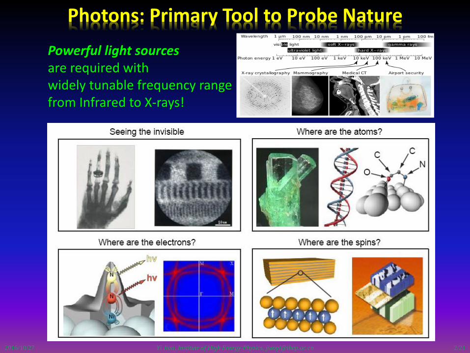
Photons: Primary Tool to Probe Nature
Powerful light sources are required with widely tunable frequency range from Infrared to X-rays!
2016/10/27 2/21
Yi Jiao, Institute of High Energy Physics, [email protected]
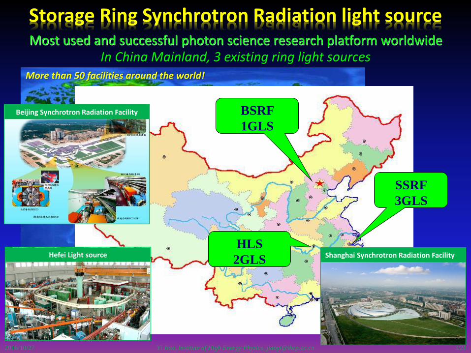
Storage Ring Synchrotron Radiation light sourceMost used and successful photon science research platform worldwide
More than 50 facilities around the world!
BSRF
1GLS
HLS
2GLS
SSRF
3GLS
Beijing Synchrotron Radiation Facility
Hefei Light source Shanghai Synchrotron Radiation Facility
2016/10/27
In China Mainland, 3 existing ring light sources
3/21

HEPSBSRF
HLSSSRF
Yi Jiao, Institute of High Energy Physics, [email protected]
HEPS: the next ring light source in China
A new photon science research center at the north of China
2016/10/27
About 60 km from the IHEP
IHEP
The HEPS-test facility (TF) project started on April 2016- R&D on the accelerator and beam line techniques for a DLSR.
4/21

Yi Jiao, Institute of High Energy Physics, [email protected]
Physical design for HEPS-TF and future HEPS project
2016/10/27
Main goals:
give a final complete and ‘optimal’ DLSR design before construction of the HEPSproject.
- compromise between Chinese technology level and innovation (e.g., lowest e0)
- compromise between user requirements and accelerator performance
give a detailed parameter list and tolerance budget table for hardware systems.
Status:
Reached a nominal design of the HEPS storage ring.
- E = 6 GeV, ex0 ~ 60 pm.rad, cir ~ 1.3 km.
Based on this design, injector (linac + booster) design, linear & nonlineardynamics study, error study, on-axis injection design, collective effects study areunderway. hardware R&D also launched.
Alternative designs with similar or different layouts being explored in phase.
5/21
Yi Jiao, Institute of High Energy Physics, [email protected]
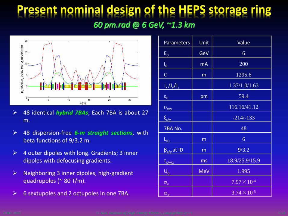
Present nominal design of the HEPS storage ring
2016/10/27
48 identical hybrid 7BAs; Each 7BA is about 27m.
48 dispersion-free 6-m straight sections, withbeta functions of 9/3.2 m.
4 outer dipoles with long. Gradients; 3 inner dipoles with defocusing gradients.
Neighboring 3 inner dipoles, high-gradient quadrupoles (~ 80 T/m).
6 sextupoles and 2 octupoles in one 7BA.
60 pm.rad @ 6 GeV, ~1.3 km
Parameters Unit Value
E0 GeV 6
I0 mA 200
C m 1295.6
Jx /Jy/Jz 1.37/1.0/1.63
e0 pm 59.4
ux/y 116.16/41.12
ξx/y -214/-133
7BA No. 48
LID m 6
βx/y at ID m 9/3.2
τx/y/z ms 18.9/25.9/15.9
U0 MeV 1.995
se 7.97×10⁻⁴
ap 3.74×10⁻⁵
6/21

Yi Jiao, Institute of High Energy Physics, [email protected]
Present nominal design, nonlinear dynamics
2016/10/27
3 sextupole families & 1 octupole family, -I transportation between sextupoles.
Tune vs. d, ring acceptances projected in the (x, y) and (x, d) planes, obtained with only the bare lattice
Integer and half integer resonances can be reached at small amplitude & momentum deviation.
7/21
Yi Jiao, Institute of High Energy Physics, [email protected]
Present nominal design, nonlinear dynamics (cont.)
2016/10/27
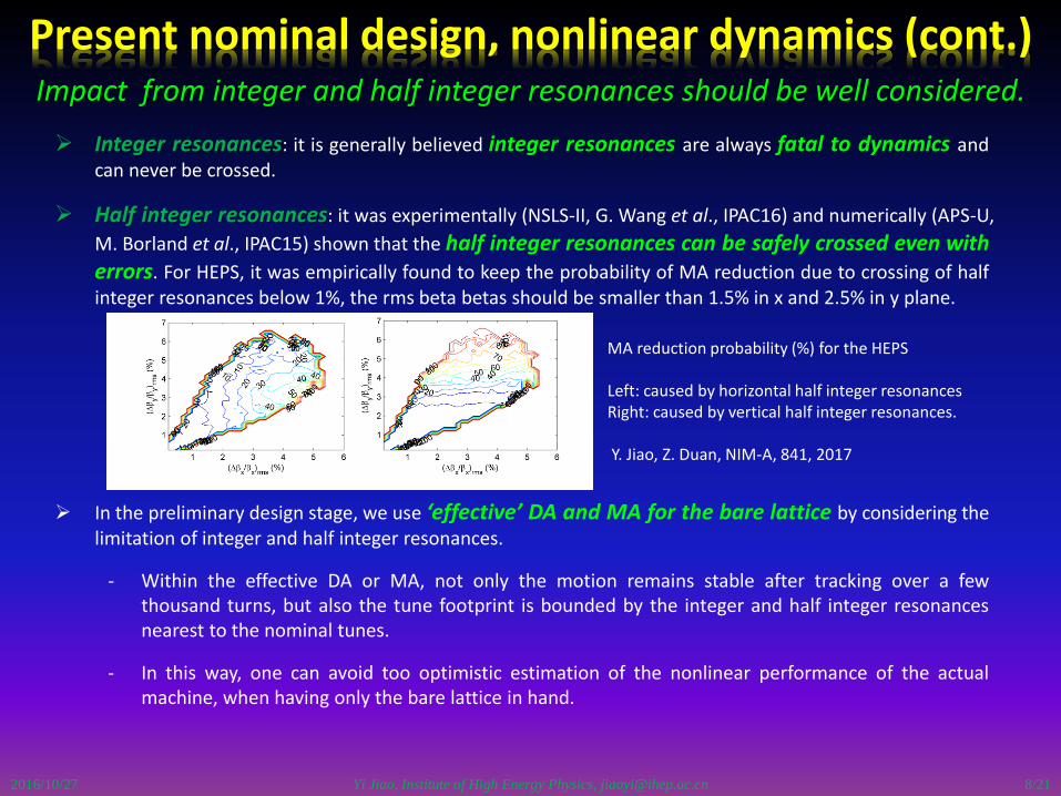
Integer resonances: it is generally believed integer resonances are always fatal to dynamics andcan never be crossed.
Half integer resonances: it was experimentally (NSLS-II, G. Wang et al., IPAC16) and numerically (APS-U,
M. Borland et al., IPAC15) shown that the half integer resonances can be safely crossed even witherrors. For HEPS, it was empirically found to keep the probability of MA reduction due to crossing of halfinteger resonances below 1%, the rms beta betas should be smaller than 1.5% in x and 2.5% in y plane.
In the preliminary design stage, we use ‘effective’ DA and MA for the bare lattice by considering thelimitation of integer and half integer resonances.
- Within the effective DA or MA, not only the motion remains stable after tracking over a fewthousand turns, but also the tune footprint is bounded by the integer and half integer resonancesnearest to the nominal tunes.
- In this way, one can avoid too optimistic estimation of the nonlinear performance of the actualmachine, when having only the bare lattice in hand.
Impact from integer and half integer resonances should be well considered.
MA reduction probability (%) for the HEPS
Left: caused by horizontal half integer resonancesRight: caused by vertical half integer resonances.
Y. Jiao, Z. Duan, NIM-A, 841, 2017
8/21

Yi Jiao, Institute of High Energy Physics, [email protected]
Present nominal design, nonlinear dynamics (cont.)
2016/10/27
Conventional DA and LMA vs. effective DA and LMA
DA for the bare lattice, ~ 5 mm(center of long straight section)
Effective DA for the bare lattice, ~ 3 mm(center of long straight section)
LMA along a 7BA obtained with only the bare latticeBlack: Particle loss in 2000 turns, ~ 4%Blue: Particle loss or cross integer resonance, mostly ~4% and ~3.5% at dispersive regionRed: Particle loss or cross integer or half integer resonance (effective LMA), ~ 3% or lower
MA size closely related to the Touschek lifetime.
For HEPS, t(Touschek) is proportional to LMA3.7
200 mA, ~650 bunches/ 720 bucketst ~ 70 hrs (with LMA of 4%) t ~ 25 hrs (with LMA of 3%)
Plan to check in the presence
of practical errors.
9/21
Yi Jiao, Institute of High Energy Physics, [email protected]
On-axis injection under consideration
2016/10/27
Longitudinal and swap-out injection
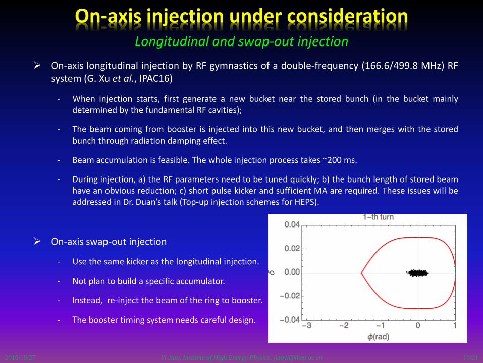
On-axis longitudinal injection by RF gymnastics of a double-frequency (166.6/499.8 MHz) RFsystem (G. Xu et al., IPAC16)
- When injection starts, first generate a new bucket near the stored bunch (in the bucket mainlydetermined by the fundamental RF cavities);
- The beam coming from booster is injected into this new bucket, and then merges with the storedbunch through radiation damping effect.
- Beam accumulation is feasible. The whole injection process takes ~200 ms.
- During injection, a) the RF parameters need to be tuned quickly; b) the bunch length of stored beamhave an obvious reduction; c) short pulse kicker and sufficient MA are required. These issues will beaddressed in Dr. Duan’s talk (Top-up injection schemes for HEPS).
On-axis swap-out injection
- Use the same kicker as the longitudinal injection.
- Not plan to build a specific accumulator.
- Instead, re-inject the beam of the ring to booster.
- The booster timing system needs careful design.
10/21

Yi Jiao, Institute of High Energy Physics, [email protected]
HEPS injector consideration
2016/10/27
Injector: Linac + booster.
Three candidate booster designs:
- 15BAs, 432 m, ~ 4 nm.rad @6 GeV.
- NSLS-II type, 432 m, dipoles withquadrupole and sextupole gradients,~ 7 nm.rad@6 GeV.
- FODO lattice, 1279 m, ~ 2nm.rad @6GeV.
Recently it was determined to adopt the15BA design.
Timing for injection
- Linac, 300 Hz, inject 30 bunches tobooster in 100 ms.
- Booster, 2 Hz, ramping period 500ms.
Parameter SpecificationRF frequency (MHz) (s-band) 2998.8 (or 2856)Single bunch Charge (nC) ≥7.2 *Energy (MeV) ≥300Relative energy spread (%) ≤0.5 (rms)Repetition rate (Hz) 300Geometric emittance (nm.rad) ≤70Pulse to pulse time jitter(ps) ≤100
Main parameters of the Linac
11/21
Yi Jiao, Institute of High Energy Physics, [email protected]
15BA booster design: in a separate tunnel
2016/10/27
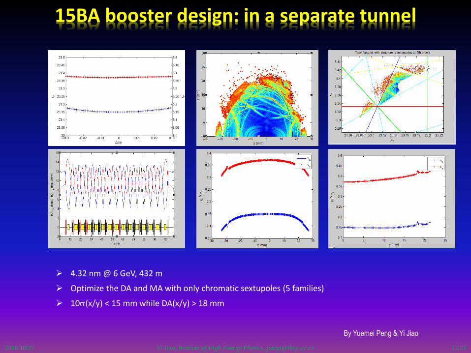
By Yuemei Peng & Yi Jiao
4.32 nm @ 6 GeV, 432 m
Optimize the DA and MA with only chromatic sextupoles (5 families)
10s(x/y) < 15 mm while DA(x/y) > 18 mm
12/21
Yi Jiao, Institute of High Energy Physics, [email protected]
Error tolerance study
2016/10/27
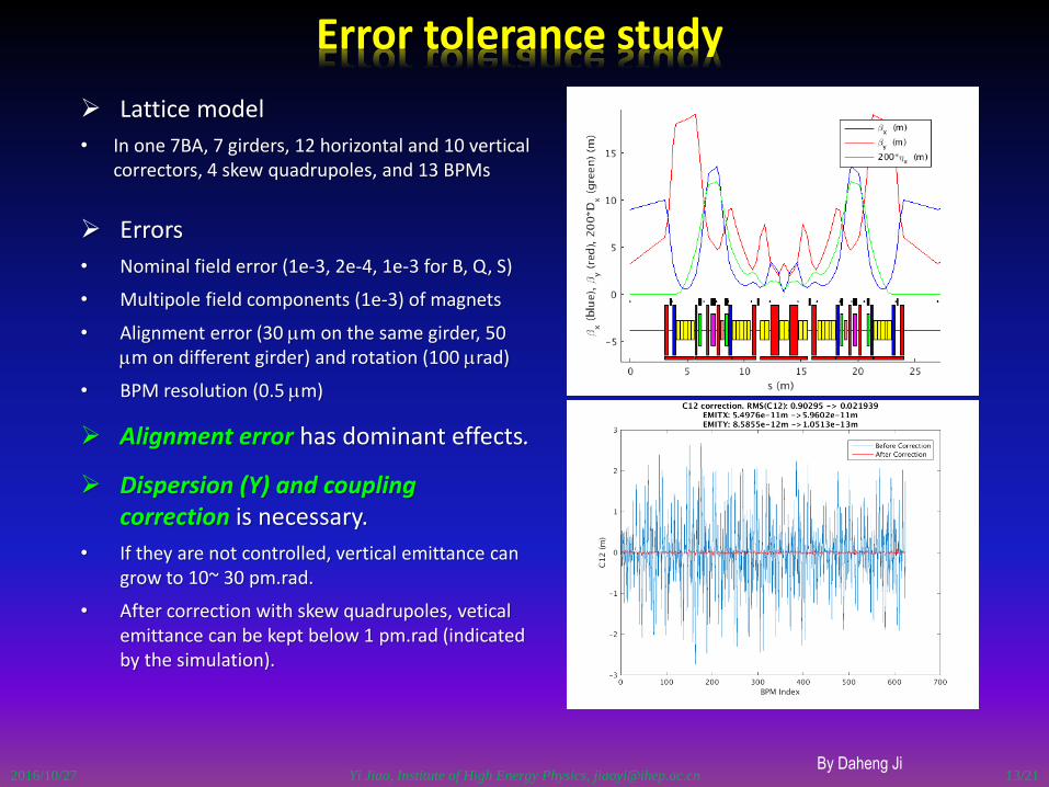
Lattice model
• In one 7BA, 7 girders, 12 horizontal and 10 vertical correctors, 4 skew quadrupoles, and 13 BPMs
Errors
• Nominal field error (1e-3, 2e-4, 1e-3 for B, Q, S)
• Multipole field components (1e-3) of magnets
• Alignment error (30 mm on the same girder, 50 mm on different girder) and rotation (100 mrad)
• BPM resolution (0.5 mm)
Alignment error has dominant effects.
Dispersion (Y) and coupling correction is necessary.
• If they are not controlled, vertical emittance can grow to 10~ 30 pm.rad.
• After correction with skew quadrupoles, veticalemittance can be kept below 1 pm.rad (indicated by the simulation).
By Daheng Ji13/21

Yi Jiao, Institute of High Energy Physics, [email protected]
ID effects: in an acceptable level
2016/10/27
Construct kick maps with Hamiltonian-Jacobin methods for 14 undulators to be installed in the first construction stage of HEPS.
By Xiaoyu Li
Planar undulator
Elliptically polarizing undulator
Induced tune shift on the order of 0.003. Obvious DA reduction, but not affects on-axis injection.
14/21
without flanges
Yi Jiao, Institute of High Energy Physics, [email protected]
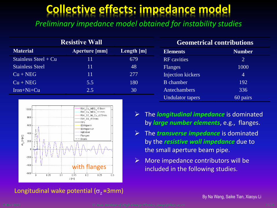
Collective effects: impedance model
2016/10/27
By Na Wang, Saike Tian, Xiaoyu Li
Resistive Wall
Material Aperture [mm] Length [m]
Stainless Steel + Cu 11 679
Stainless Steel 11 48
Cu + NEG 11 277
Cu + NEG 5.5 180
Iron+Ni+Cu 2.5 30
Geometrical contributions
Elements Number
RF cavities 2
Flanges 1000
Injection kickers 4
B chamber 192
Antechambers 336
Undulator tapers 60 pairs
The longitudinal impedance is dominated by large number elements, e.g., flanges.
The transverse impedance is dominated by the resistive wall impedance due to the small aperture beam pipe.
More impedance contributors will be included in the following studies.
Longitudinal wake potential (sz =3mm)
with flanges
Preliminary impedance model obtained for instability studies
15/21
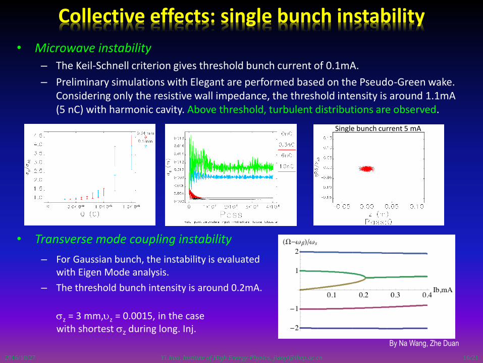
• Microwave instability
– The Keil-Schnell criterion gives threshold bunch current of 0.1mA.
– Preliminary simulations with Elegant are performed based on the Pseudo-Green wake. Considering only the resistive wall impedance, the threshold intensity is around 1.1mA (5 nC) with harmonic cavity. Above threshold, turbulent distributions are observed.
• Transverse mode coupling instability
Yi Jiao, Institute of High Energy Physics, [email protected]
Collective effects: single bunch instability
2016/10/27
By Na Wang, Zhe Duan
– For Gaussian bunch, the instability is evaluated with Eigen Mode analysis.
– The threshold bunch intensity is around 0.2mA.
sz = 3 mm,uz = 0.0015, in the case with shortest sz during long. Inj.
Single bunch current 5 mA
16/21
Yi Jiao, Institute of High Energy Physics, [email protected]
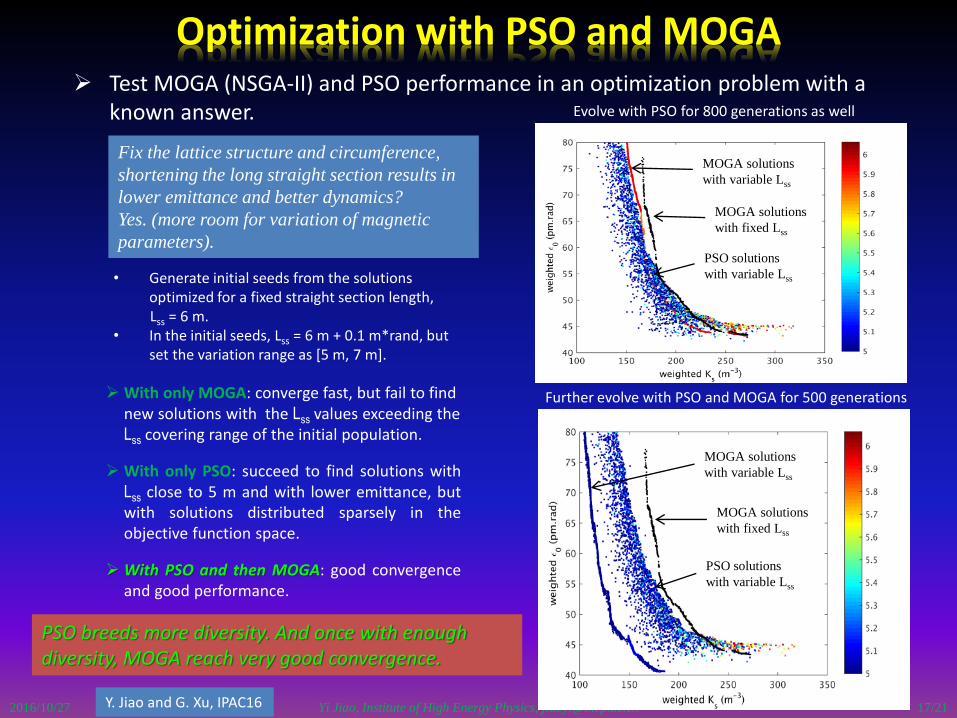
Optimization with PSO and MOGA
2016/10/27
Test MOGA (NSGA-II) and PSO performance in an optimization problem with a known answer.
Y. Jiao and G. Xu, IPAC16
PSO solutions
with variable Lss
MOGA solutions
with variable Lss
MOGA solutions
with fixed Lss
PSO solutions
with variable Lss
MOGA solutions
with variable Lss
MOGA solutions
with fixed Lss
Fix the lattice structure and circumference,
shortening the long straight section results in
lower emittance and better dynamics?
Yes. (more room for variation of magnetic
parameters).
With only MOGA: converge fast, but fail to find new solutions with the Lss values exceeding the Lss covering range of the initial population.
With only PSO: succeed to find solutions withLss close to 5 m and with lower emittance, butwith solutions distributed sparsely in theobjective function space.
With PSO and then MOGA: good convergenceand good performance.
Evolve with PSO for 800 generations as well
Further evolve with PSO and MOGA for 500 generations
• Generate initial seeds from the solutions optimized for a fixed straight section length, Lss = 6 m.
• In the initial seeds, Lss = 6 m + 0.1 m*rand, but set the variation range as [5 m, 7 m].
PSO breeds more diversity. And once with enough diversity, MOGA reach very good convergence.
17/21
Yi Jiao, Institute of High Energy Physics, [email protected]
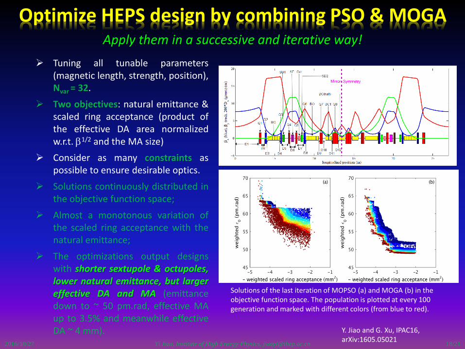
Optimize HEPS design by combining PSO & MOGA
2016/10/27
Tuning all tunable parameters(magnetic length, strength, position),Nvar = 32.
Two objectives: natural emittance &scaled ring acceptance (product ofthe effective DA area normalizedw.r.t. b1/2 and the MA size)
Consider as many constraints aspossible to ensure desirable optics.
Solutions continuously distributed inthe objective function space;
Almost a monotonous variation ofthe scaled ring acceptance with thenatural emittance;
The optimizations output designswith shorter sextupole & octupoles,lower natural emittance, but largereffective DA and MA (emittancedown to ~ 50 pm.rad, effective MAup to 3.5% and meanwhile effectiveDA ~ 4 mm).
Apply them in a successive and iterative way!
Y. Jiao and G. Xu, IPAC16, arXiv:1605.05021
Solutions of the last iteration of MOPSO (a) and MOGA (b) in the objective function space. The population is plotted at every 100 generation and marked with different colors (from blue to red).
18/21

Yi Jiao, Institute of High Energy Physics, [email protected]/10/27
Enlarging DA by replacing two ID sections with high-beta sections
The same emittance, with circumferenceincreased by ~ 1.5% (20 m).
Alternative design accommodating off-axis injection
19/21

Yi Jiao, Institute of High Energy Physics, [email protected]
In Closing…
HEPS will be the next storage ring light source with high
energy and low emittance in China, and the HEPS test
facility has been started.
A nominal design of the HEPS storage ring was reached.
Based on this design, related physical studies are under
way.
Many challenging and also interesting issues need to be
explored, and iteration of design is necessary.
2016/10/27 20/21
2016/10/27 Yi Jiao, Institute of High Energy Physics, [email protected] 21/21
Yi Jiao, Institute of High Energy Physics, [email protected]
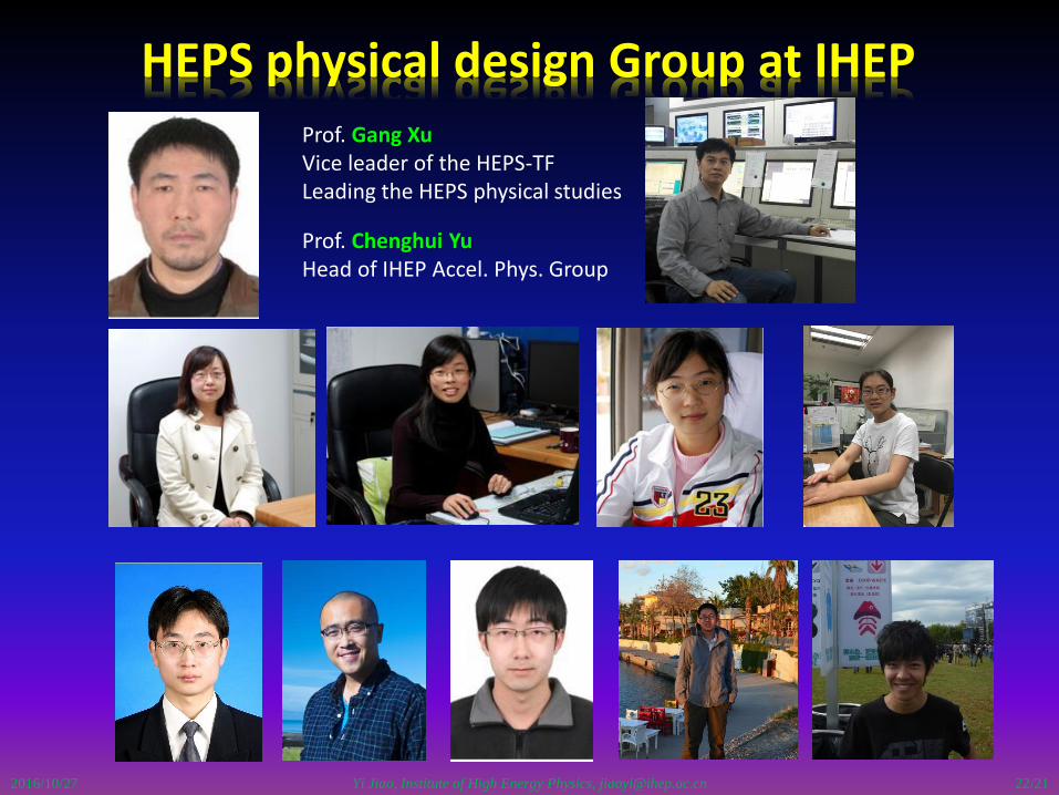
HEPS physical design Group at IHEP
2016/10/27
Prof. Gang XuVice leader of the HEPS-TFLeading the HEPS physical studies
Prof. Chenghui YuHead of IHEP Accel. Phys. Group
22/21