lateral stress caused by horizontal and vertical surcharge...
TRANSCRIPT

INTERNATIONAL JOURNAL FOR NUMERICAL AND ANALYTICAL METHODS IN GEOMECHANICSInt. J. Numer. Anal. Meth. Geomech., 2005; 29:1341–1361Published online 29 July 2005 in Wiley InterScience (www.interscience.wiley.com). DOI: 10.1002/nag.462
Lateral stress caused by horizontal and vertical surchargestrip loads on a cross-anisotropic backfill
Cheng-Der Wangn,y,z
Department of Civil and Disaster Prevention Engineering, National United University,
No. 1, Lien-Da, Kung-Ching-Li, Miao-Li, 360, Taiwan, ROC
SUMMARY
This study derives analytical solutions for estimating the lateral stress caused by horizontal and verticalsurcharge strip loads resting on a cross-anisotropic backfill. The following loading types are employed inthis work: point load, line load, uniform strip load, upward linear-varying strip load, upward nonlinear-varying strip load, downward linear-varying strip load and downward nonlinear-varying strip load. Thecross-anisotropic planes are assumed to be parallel to the horizontal surface of the backfill. The solutionsproposed herein have never been mentioned in previous literature, but can be derived by integrating thepoint load solution in a Cartesian co-ordinate system for a cross-anisotropic medium. The calculations bythe presented solutions are quick and accurate since they are concise and systematized. Additionally, theproposed calculations demonstrate that the type and degree of material anisotropy and the horizontal/vertical loading types decisively influence the lateral stress. This investigation presents examples of theproposed horizontal and vertical strip loads acting on the surface of the isotropic and cross-anisotropicbackfills to elucidate their effects on the stress. The analytical results reveal that the stress distributionsaccounting for soil anisotropy and loading types are quite different from those computed from theavailable isotropic solutions. Restated, the derived solutions, as well as realistically simulating the actualsurcharge loading circumstances, provide a good reference for the design of retaining structures for thebackfill materials are cross-anisotropic. Copyright # 2005 John Wiley & Sons, Ltd.
KEY WORDS: analytical solutions; lateral stress; horizontal and vertical surcharge strip loads; cross-anisotropic backfill; point load; Cartesian co-ordinate system
INTRODUCTION
In engineering, the retaining structure is frequently subjected to surcharge loads on its backfill.The superimposed surface loads could be any loading comprising point loads, such as truckwheels, or distributed loads, such as foundations of adjacent buildings, highway pavements andrailroad tracks. When the surcharge loads on the backfill close enough to the wall, additionallateral pressure could be generated [1–3]. Thus, the magnitude and distribution of lateral stress
Received 14 August 2004Revised 8 May 2005
Accepted 15 June 2005Copyright # 2005 John Wiley & Sons, Ltd.
yE-mail: [email protected], [email protected] Professor.
nCorrespondence to: Cheng-Der Wang, Department of Civil and Disaster Prevention Engineering, National UnitedUniversity, No. 1, Lien-Da, Kung-Ching-Li, Miao-Li, 360, Taiwan, ROC.

on the retaining wall caused by loads superimposed upon the surface of the backfill are ofinterest in geotechnical engineering [4–6]. Previously, the backfill material typically has beenassumed to be homogeneous, linearly elastic and isotropically continuous. The classicalisotropic elastic solutions for loads applied to the surface of a half-space, readily available intexts such as Poulos and Davis [7] and Clayton et al. [8], are applied to predict the lateral stressincrease on a wall at any depth. However, this study recognizes that soils are not generallyisotropic materials. Normally, most soils exhibit an axial or transverse isotropic structure oftenreferred to as cross-anisotropic, with identical properties in all directions within the horizontalplane, which are different from the properties in the vertical direction, which is the direction ofdeposition. Hence, better results can only be yielded by considering anisotropic deformability[9–16]. This work derived analytical solutions for lateral stress resulting from a horizontal/vertical line load, and various horizontal/vertical strip loads acting on the cross-anisotropicbackfill.
The theory of elasticity method is well known to be applicable in computing the lateralpressure profile against the wall from the surface surcharge loading [17]. The general validity ofusing the Boussinesq’s solution [18] for surcharges was established in several publications,including Spangler [1, 19,20], Spangler and Handy [21], Spangler and Mickle [4], Rehnman andBroms [22] and others [17]. Engineers at the Iowa Engineering Experiment Station performed aseries of experiments to determine the lateral pressure on a wall due to concentrated loadsapplied at the backfill surface and the uniformly distributed line or strip loads parallel to thewall. These experiments indicated that the surface loads produced lateral pressures which wereclosely related to the pressures calculated by the Boussinesq’s solution [18] in a semi-infiniteelastic medium, and they also provided a basis for further study of the effect of loads applied atthe backfill surface [4]. Nevertheless, the above-mentioned experiments showed that themeasured lateral pressure was about twice that computed by the Boussinesq’s solution [18]within the half-space with Poisson’s ratio ¼ 0:5: Mindlin [23] discussed Spangler’s work [19],and suggested that the doubling of the elastic solution [18] could be explained by applying animage-based approach to a perfectly smooth rigid retaining wall. This configuration might causea mirror load to be placed symmetrically in front of the wall. Mindlin [23] demonstrated that thehorizontal displacements at the rigid wall would be zero, enabling his method to be invoked topredict the lateral stress [8]. Hence, the resulting stress is about twice that obtained using theBoussinesq’s solution [18]. Rehnman and Broms [24] revealed that the lateral pressure frompoint loads when the soil behind the wall was dense was much lower than when the soil wasloose, and that the gravelly backfill generated higher pressure than finer-grained materials. Thisobservation indicated that both the soil state and Poisson’s ratio were significant parameters forthe lateral stress. Misra [25] theoretically measured the variation of lateral pressure distributionresulting from different types of granular backfill subjected to various levels of contact pressureon its surface using the equation, E=G > 2ð1þ nÞ: Jarquio [26] derived a simplified expression fordetermining the centroid of total lateral surcharge pressure, and the point of maximum unitlateral pressure for both yielding and unyielding retaining wall structures. The author is notaware of any proposed analyses of lateral stress for a cross-anisotropic backfill caused bysurcharge loads. In deriving the proposed solutions, the backfill material is assumed to be ahomogeneous, linearly elastic and cross-anisotropic continuum. The retaining wall is verticalwith horizontal backfill, that is, the cross-anisotropic planes are parallel to the boundary plane.Additionally, this investigation applies two simplifying assumptions: (1) the wall does not move,and (2) the wall is perfectly smooth (no friction between the wall and the soil). Under these
Copyright # 2005 John Wiley & Sons, Ltd. Int. J. Numer. Anal. Meth. Geomech. 2005; 29:1341–1361
C.-D. WANG1342

circumstances, the induced lateral stress on the wall would be the same as the induced horizontalstress in an elastic half-space by two loads of equal magnitude [27]. Hence, seven cases ofhorizontal and vertical loading are explored as follows:
Case A: horizontal/vertical point load, P/Q (force).Case B: horizontal/vertical line load, Pl=Ql (force per unit length).Case C: horizontal/vertical uniform strip load, Ps=Qs (force per unit area).Case D: horizontal/vertical upward linear-varying strip load, Ps=Qs (maximum force per unit
area).Case E: horizontal/vertical upward nonlinear-varying strip load, Ps=Qs (maximum force per
unit area).Case F: horizontal/vertical downward linear-varying strip load, Ps=Qs (maximum force per
unit area).Case G: horizontal/vertical downward nonlinear-varying strip load, Ps=Qs (maximum force
per unit area).
The exact solutions proposed in this article can be directly obtained by integrating the pointload solutions in a Cartesian co-ordinate system for a cross-anisotropic medium [28]. Thederived solutions are clear and concise, and show that the type and degree of materialanisotropy, and different horizontal/vertical loading types deeply influence the induced lateralstress. Two examples are presented at the end of this study to illustrate the ratio of anisotropicto isotropic lateral stress in the isotropic/cross-anisotropic backfills owing to a horizontal/vertical uniform strip load, a horizontal/vertical upward linear-varying strip load and ahorizontal/vertical upward nonlinear-varying strip load.
CASE A: LATERAL STRESS CAUSED BY A HORIZONTAL/VERTICAL POINT LOAD
In this work, the solutions of lateral stress caused by horizontal/vertical surcharge strip loads ona cross-anisotropic backfill are obtained by integrating the point load solution in a Cartesian co-ordinate system [28]. The cross-anisotropic planes are assumed to be parallel to the horizontalground surface. Figure 1 depicts the proposed approaches for solving the lateral stress subjectedto a horizontal point load P, and a vertical point load Q, which as the form of body forces
Traction free
Q Q
(0, 0, h) P (0, 0, h) P (0, 0, h)
z z z
(I) (II)
Figure 1. Superposition approach to the point loading half-space problem.
Copyright # 2005 John Wiley & Sons, Ltd. Int. J. Numer. Anal. Meth. Geomech. 2005; 29:1341–1361
SURCHARGE STRIP LOADS ON A CROSS-ANISOTROPIC BACKFILL 1343

[29, point load solutions presented in terms of the cylindrical co-ordinate system]. Figure 1demonstrates that a half-space comprises two full-spaces, one with a horizontal/vertical pointload in its interior ð0; 0; hÞ; and the other with opposite traction of the first full-space alongz ¼ 0: The traction in the first full-space along z ¼ 0 results from the point load. The solutionsfor the half-space are thus derived by superposing the solutions of the two full-spaces. Restated,the solutions can be obtained from the governing equations for a full-space (including thegeneral solutions (I) and homogeneous solutions (II)) by adhering to the traction-free boundaryconditions on the half-space surface. If h ¼ 0; then the horizontal/vertical point load is appliedto the surface. Moreover, since the surcharge is usually applied a certain distance from the wall,the distance at which a load is applied should be considered [5]. Therefore, this work applied thehorizontal/vertical point load, P=Q; at a horizontal distance of a from the retaining wall withheight Hðx ¼ a; y ¼ 0; z ¼ 0Þ; as revealed in Figure 2(a). Thus, the solutions for lateral stresson a cross-anisotropic backfill can be directly integrated from the point load solutions [28].Figures 2(b)–(g), respectively, display solutions for lateral stress owing to a horizontal/verticalline load, a horizontal/vertical uniform strip load, a horizontal/vertical upward linear-varyingstrip load, a horizontal/vertical upward nonlinear-varying strip load, a horizontal/verticaldownward linear-varying strip load and a horizontal/vertical downward nonlinear-varying stripload. The analytical solution for horizontal stress ðspxxÞ in the Cartesian co-ordinate systemsubjected to a horizontal point load P, and a vertical point load Q, on the surface of a cross-anisotropic medium can be recast as follows:
spxx ¼P
2pkðm2u1 �m1u2Þm1m2ðu1 � u2Þ
� �A44ðu21ps11 � u22ps12Þ
�2A66u1
m1 þ u1ps21 �
u2
m2 þ u2ps22
� ��þ 2u3ps23
�
þQ
2pkðm2u1 �m1u2Þ
u1 � u2
�A44ðu1ps31 � u2ps32Þ
�2A661
m1 þ u1ðps31 � ps41Þ �
1
m2 þ u2ðps32 � ps42Þ
� ��ð1Þ
However, for a perfectly smooth rigid retaining wall, the lateral stress ðsphÞ is assumed to betwice as great as that calculated from the cross-anisotropic point load solution (Equation (1)).Hence, Equation (1) can be further rewritten as
sph ¼ 2*P
2pkðm2u1 �m1u2Þm1m2ðu1 � u2Þ
� �A44ðu21ps11 � u22ps12Þ
�2A66u1
m1 þ u1ps21 �
u2
m2 þ u2ps22
� ��þ 2u3ps23
�
þ 2*Q
2pkðm2u1 �m1u2Þ
u1 � u2
�A44ðu1ps31 � u2ps32Þ
�2A661
m1 þ u1ðps31 � ps41Þ �
1
m2 þ u2ðps32 � ps42Þ
� ��ð2Þ
Copyright # 2005 John Wiley & Sons, Ltd. Int. J. Numer. Anal. Meth. Geomech. 2005; 29:1341–1361
C.-D. WANG1344

Figure 2. Lateral stress caused by various types of horizontal/vertical surcharge loads on a cross-anisotropic backfill: (a) point load case; (b) line load case; (c) uniform strip load case; (d) upward linear-varying strip load case; (e) upward nonlinear-varying strip load case; (f) downward linear-varying strip
load case; and (g) downward nonlinear-varying strip load case.
Copyright # 2005 John Wiley & Sons, Ltd. Int. J. Numer. Anal. Meth. Geomech. 2005; 29:1341–1361
SURCHARGE STRIP LOADS ON A CROSS-ANISOTROPIC BACKFILL 1345

* The generalized Hooke’s law for the cross-anisotropic medium in a Cartesian co-ordinatesystem can be adopted to express the constitutive equations employed herein as
sxx ¼ A11exx þ ðA11 � 2A66Þeyy þ A13ezz ð3Þ
syy ¼ ðA11 � 2A66Þexx þ A11eyy þ A13ezz ð4Þ
szz ¼ A13ðexx þ eyyÞ þ A33ezz ð5Þ
txy ¼ A66gxy ð6Þ
tyz ¼ A44gyz ð7Þ
txz ¼ A44gxz ð8Þ
Aij ði; j ¼ 126Þ denote the elastic moduli or elasticity constants of the medium [29, 30]. For across-anisotropic material, the five engineering elastic constants, E;E0; n; n0; and G0 are defined as[31]
1. E represents the Young’s modulus in the horizontal direction.2. E0 represents the Young’s modulus in the vertical direction.3. n represents the Poisson’s ratio for the effect of horizontal stress on complementary
horizontal strain.4. n0 represents the Poisson’s ratio for the effect of vertical stress on horizontal strain.5. G0 represents the shear modulus in the vertical plane.
Hence, Aij ði; j ¼ 126Þ can be expressed in terms of these elastic constants as
A11 ¼Eð1� ðE=E0Þu02Þ
ð1þ uÞð1� u� ð2E=E0Þu02Þ; A13 ¼
Eu0
1� u� ð2E=E0Þ u02
A33 ¼E0ð1� uÞ
1� u� ð2E=E0Þu02; A44 ¼ G0; A66 ¼
E
2ð1þ uÞ
ð9Þ
* Thermodynamic constraints stipulate that the strain energy of an elastic material shouldalways be positive. Therefore, the theoretical bounding values of the relevant elasticparameters are described as [11, 32]:
E;E 0;G;G0 > 0 ð10Þ
�15n51; �
ffiffiffiffiffiffiffiffiffiffiffiffiffiffiffiffiE0
E
1� u2
r5u05
ffiffiffiffiffiffiffiffiffiffiffiffiffiffiffiffiE0
E
1� u2
rð11Þ
Copyright # 2005 John Wiley & Sons, Ltd. Int. J. Numer. Anal. Meth. Geomech. 2005; 29:1341–1361
C.-D. WANG1346
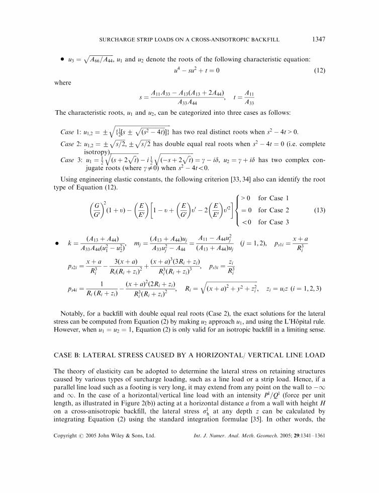
* u3 ¼ffiffiffiffiffiffiffiffiffiffiffiffiffiffiffiffiffiA66=A44
p; u1 and u2 denote the roots of the following characteristic equation:
u4 � su2 þ t ¼ 0 ð12Þ
where
s ¼A11A33 � A13ðA13 þ 2A44Þ
A33A44; t ¼
A11
A33
The characteristic roots, u1 and u2; can be categorized into three cases as follows:
Case 1: u1;2 ¼ �ffiffiffiffiffiffiffiffiffiffiffiffiffiffiffiffiffiffiffiffiffiffiffiffiffiffiffiffiffiffiffiffiffiffiffiffiffiffiffiffif12½s�
ffiffiffiffiffiffiffiffiffiffiffiffiffiffiffiffiffiðs2 � 4tÞ
p�g
qhas two real distinct roots when s2 � 4t > 0:
Case 2: u1;2 ¼ �ffiffiffiffiffiffiffis=2
p;�
ffiffiffiffiffiffiffis=2
phas double equal real roots when s2 � 4t ¼ 0 (i.e. complete
isotropy).Case 3: u1 ¼ 1
2
ffiffiffiffiffiffiffiffiffiffiffiffiffiffiffiffiffiffiffiffiðsþ 2
ffiffit
pÞ
q� i 1
2
ffiffiffiffiffiffiffiffiffiffiffiffiffiffiffiffiffiffiffiffiffiffiffiffið�sþ 2
ffiffit
pÞ
q¼ g� id; u2 ¼ gþ id has two complex con-
jugate roots (where g=0) when s2 � 4t50:
Using engineering elastic constants, the following criterion [33, 34] also can identify the roottype of Equation (12).
G
G0
� �2ð1þ uÞ �
E
E0
� �1� uþ
E
G0
� �u0 � 2
E
E 0
� �u02
� � > 0 for Case 1
¼ 0 for Case 2
50 for Case 3
8>><>>: ð13Þ
* k ¼ðA13 þ A44Þ
A33A44ðu21 � u22Þ; mj ¼
ðA13 þ A44ÞujA33u
2j � A44
¼A11 � A44u
2j
ðA13 þ A44Þujðj ¼ 1; 2Þ; ps1i ¼
xþ a
R3i
ps2i ¼xþ a
R3i
�3ðxþ aÞ
RiðRi þ ziÞ2þðxþ aÞ3ð3Ri þ ziÞ
R3i ðRi þ ziÞ
3; ps3i ¼
zi
R3i
ps4i ¼1
Ri ðRi þ ziÞ�ðxþ aÞ2ð2Ri þ ziÞ
R3i ðRi þ ziÞ
2; Ri ¼
ffiffiffiffiffiffiffiffiffiffiffiffiffiffiffiffiffiffiffiffiffiffiffiffiffiffiffiffiffiffiffiffiffiffiffiffiffiðxþ aÞ2 þ y2 þ z2i
q; zi ¼ uiz ði ¼ 1; 2; 3Þ
Notably, for a backfill with double equal real roots (Case 2), the exact solutions for the lateralstress can be computed from Equation (2) by making u2 approach u1; and using the L’Hopital rule.However, when u1 ¼ u2 ¼ 1; Equation (2) is only valid for an isotropic backfill in a limiting sense.
CASE B: LATERAL STRESS CAUSED BY A HORIZONTAL/ VERTICAL LINE LOAD
The theory of elasticity can be adopted to determine the lateral stress on retaining structurescaused by various types of surcharge loading, such as a line load or a strip load. Hence, if aparallel line load such as a footing is very long, it may extend from any point on the wall to �1and 1: In the case of a horizontal/vertical line load with an intensity Pl=Ql (force per unitlength, as illustrated in Figure 2(b)) acting at a horizontal distance a from a wall with height Hon a cross-anisotropic backfill, the lateral stress slh at any depth z can be calculated byintegrating Equation (2) using the standard integration formulae [35]. In other words, the
Copyright # 2005 John Wiley & Sons, Ltd. Int. J. Numer. Anal. Meth. Geomech. 2005; 29:1341–1361
SURCHARGE STRIP LOADS ON A CROSS-ANISOTROPIC BACKFILL 1347

analytical solution slh can be obtained by integrating Equation (2) in the y direction from �1 to1 as follows:
slh ¼Z 1�1
sph dy ð14Þ
The solution for lateral stress due to a horizontal/vertical line load resting on a cross-anisotropic backfill can be written as
slh ¼ 2*Pl*n*
u21ðxþ aÞ
ðxþ aÞ2 þ ðu1zÞ2�
u22ðxþ aÞ
ðxþ aÞ2 þ ðu2zÞ2
� �
þ 2*Ql*n*m1 *m2 *
u21z
ðxþ aÞ2 þ ðu1zÞ2�
u22z
ðxþ aÞ2 þ ðu2zÞ2
� �ð15Þ
where n ¼ A44kðm2u1 �m1u2Þ=pm1m2ðu1 � u2Þ:
CASE C: LATERAL STRESS CAUSED BY A HORIZONTAL/VERTICALUNIFORM STRIP LOAD
Retaining wall structures supporting continuous wall footing, highway and railroad loading arepractical examples applying the strip load surcharge [26]. Figure 2(c) in this section depicts ahorizontal/vertical uniform strip load with an intensity Ps=Qs (force per unit area) and width b,at a horizontal distance a from a wall with height H on a cross-anisotropic backfill. To solve thelateral stress induced by this load, the complete solution can be obtained by integrating the lineload solution (s1h; Equation (15)) in the x direction between the limits 0 and b to describe asurcharge load uniformly distributed on a strip, as follows:
suh ¼Z b
0
slh dx ð16Þ
where suh denotes the lateral stress caused by a horizontal/vertical uniform strip load. Uponintegration, the explicit solution can be given by
suh ¼ 2*Ps*n*ðu
21Ic1 � u22Ic2Þ þ 2*Q
s*n*m1 *m2 * ðu1Id1 � u2Id2Þ ð17Þ
where
Icj ¼ ln
ffiffiffiffiffiffiffiffiffiffiffiffiffiffiffiffiffiffiffiffiffiffiffiffiffiffiffiffiffiffiffiffiffiffiffiffiffiffiffiffiffiffiffiffiffiffiffiðða=ujzÞ þ ðb=ujzÞÞ
2 þ 1
qffiffiffiffiffiffiffiffiffiffiffiffiffiffiffiffiffiffiffiffiffiffiffiffiða=ujzÞ
2 þ 1
q�������
�������; Idj ¼ tan�1a
ujzþ
b
ujz
� �� tan�1
a
ujz
� �ð j ¼ 1; 2Þ
Equation (17) shows that Icj and Idj are both functions of a=ujz and b=ujz ðj ¼ 1; 2Þ: Therefore, ifthe five engineering elastic constants E;E0; n; n0; and G0 are given, then the characteristic rootuj ð j ¼ 1; 2Þ can be computed using Equations (9) and (12). Figures 3 and 4 plot the calculationcharts for Icj and Idj ; with variable nondimensional factors, a=ujz and b=ujz; in which a=ujz is inthe range 0.01–10, and b=ujz is in the range 0.1–10. These figures can be utilized when computersor calculators are unavailable, but are only appropriate for the root type of the characteristic
Copyright # 2005 John Wiley & Sons, Ltd. Int. J. Numer. Anal. Meth. Geomech. 2005; 29:1341–1361
C.-D. WANG1348

equation (Equation (13)) belonging to Case 1 (i.e. where u1 and u2 are two real distinct roots).Hence, if the root type belongs to Case 2 or Case 3, the presented calculation charts (Figures 3and 4) cannot be employed to calculate the lateral stress due to a horizontal/vertical uniformstrip load.
CASE D: LATERAL STRESS CAUSED BY A HORIZONTAL/VERTICALUPWARD LINEAR-VARYING STRIP LOAD
For an induced horizontal/vertical load with a nonuniform distribution, a horizontal/verticalupward linear-varying strip load is first used. Figure 2(d) indicates that the load is upwardlinearly varied in the x direction from 0 (at x ¼ a) to the maximum magnitude Ps (at x ¼ aþ b),
0.01 0.1 1 100
0.4
0.8
1.2
1.6
2
2.4
0.01 0.1 1 100
0.4
0.8
1.2
1.6
2
2.4
I cj
0.01 0.1 1 100.02 0.03 0.05 0.2 0.3 0.5 2 3 5
auj*z
buj*z=10
9
8
7
6
54
3
21.81.61.41.2
1.00.90.80.70.60.50.40.30.20.1
Figure 3. Calculation chart for Icj :
Copyright # 2005 John Wiley & Sons, Ltd. Int. J. Numer. Anal. Meth. Geomech. 2005; 29:1341–1361
SURCHARGE STRIP LOADS ON A CROSS-ANISOTROPIC BACKFILL 1349

on a strip with width b. The lateral stress su linh is given by directly integrating the line load
solution (slh; Equation (15)) as follows:
su linh ¼
Z b
0
x
b
*s
lh dx
¼ 2*Ps*n* u21 1�
u1z
b
Id1 �
a
b
Ic1
h i� u22 1�
u2z
b
Id2 �
a
b
Ic2
h in o� 2*Q
s*n*m1 *m2 * u1
a
b
Id1 �
u1z
b
Ic1
h i� u2
a
b
Id2 �
u2z
b
Ic2
h in oð18Þ
where Ps=Qs represents the maximum horizontal/vertical upward linear-varying strip load (forceper unit area). If computers or calculators are unavailable, calculation charts in Figures 3 and 4can also be utilized to estimate the desired stress if the root type of a cross-anisotropic backfillbelongs to Case 1.
0.01 0.1 1 100.02 0.03 0.05 0.2 0.3 0.5 2 3 5
auj*z
0
0.3
0.6
0.9
1.2
1.5
I dj
buj*z=10
0.1
0.2
0.3
0.4
0.5
0.6
0.7
0.80.9
1.0
1.2
1.41.61.82
3
456
87
9
Figure 4. Calculation chart for Idj :
Copyright # 2005 John Wiley & Sons, Ltd. Int. J. Numer. Anal. Meth. Geomech. 2005; 29:1341–1361
C.-D. WANG1350
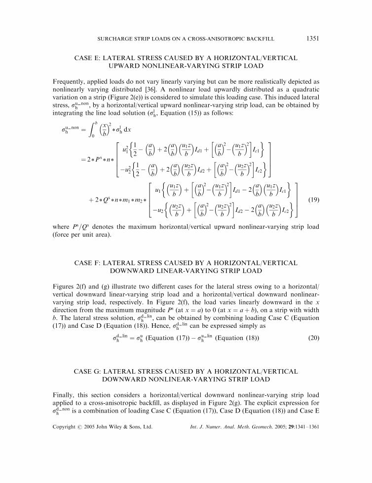
CASE E: LATERAL STRESS CAUSED BY A HORIZONTAL/VERTICALUPWARD NONLINEAR-VARYING STRIP LOAD
Frequently, applied loads do not vary linearly varying but can be more realistically depicted asnonlinearly varying distributed [36]. A nonlinear load upwardly distributed as a quadraticvariation on a strip (Figure 2(e)) is considered to simulate this loading case. This induced lateralstress, su non
h ; by a horizontal/vertical upward nonlinear-varying strip load, can be obtained byintegrating the line load solution (slh; Equation (15)) as follows:
su nonh ¼
Z b
0
x
b
2*s
lh dx
¼ 2*Ps*n*
u211
2�
a
b
þ 2
a
b
u1z
b
Id1 þ
a
b
2�
u1z
b
2� �Ic1
� �
�u221
2�
a
b
þ 2
a
b
u2z
b
Id2 þ
a
b
2�
u2z
b
2� �Ic2
� �26664
37775
þ 2*Qs*n*m1 *m2 *
u1u1z
b
þ
a
b
2�
u1z
b
2� �Id1 � 2
a
b
u1z
b
Ic1
� �
�u2u2z
b
þ
a
b
2�
u2z
b
2� �Id2 � 2
a
b
u2z
b
Ic2
� �26664
37775 ð19Þ
where Ps=Qs denotes the maximum horizontal/vertical upward nonlinear-varying strip load(force per unit area).
CASE F: LATERAL STRESS CAUSED BY A HORIZONTAL/VERTICALDOWNWARD LINEAR-VARYING STRIP LOAD
Figures 2(f) and (g) illustrate two different cases for the lateral stress owing to a horizontal/vertical downward linear-varying strip load and a horizontal/vertical downward nonlinear-varying strip load, respectively. In Figure 2(f), the load varies linearly downward in the xdirection from the maximum magnitude Ps (at x ¼ a) to 0 (at x ¼ aþ b), on a strip with widthb. The lateral stress solution, sd lin
h ; can be obtained by combining loading Case C (Equation(17)) and Case D (Equation (18)). Hence, sd lin
h can be expressed simply as
sd linh ¼ suh ðEquation ð17ÞÞ � su lin
h ðEquation ð18ÞÞ ð20Þ
CASE G: LATERAL STRESS CAUSED BY A HORIZONTAL/VERTICALDOWNWARD NONLINEAR-VARYING STRIP LOAD
Finally, this section considers a horizontal/vertical downward nonlinear-varying strip loadapplied to a cross-anisotropic backfill, as displayed in Figure 2(g). The explicit expression forsd nonh is a combination of loading Case C (Equation (17)), Case D (Equation (18)) and Case E
Copyright # 2005 John Wiley & Sons, Ltd. Int. J. Numer. Anal. Meth. Geomech. 2005; 29:1341–1361
SURCHARGE STRIP LOADS ON A CROSS-ANISOTROPIC BACKFILL 1351

(Equation (19)). Therefore, sd nonh is written as
sd nonh ¼ suh ðEquation ð17ÞÞ � 2*s
u linh ðEquation ð18ÞÞ þ su non
h ðEquation ð19ÞÞ ð21Þ
Table I summarizes the proposed solutions, listing loading Cases C–G with respect to theinduced lateral stress solutions. Based on Table I, the lateral stress caused by any conceivablesurcharge strip load can also be analysed by superposing the presented loading cases. Figure 5shows a flow chart for computing the lateral stress by the presented loading cases using thecalculation charts, Icj and Idj ðj ¼ 122Þ (Figures 3 and 4). Although the two charts are suppliedfor the five engineering elastic constants of a cross-anisotropic backfill belonging to Case 1, theyprovide an alternative tool for calculating the induced lateral stress quickly and accurately.
ILLUSTRATIVE EXAMPLES
This section describes a parametric study which was undertaken to confirm the derived solutionsand to elucidate the effect of the type and degree of material anisotropy, and the loading type,on the lateral stress. For typical ranges of cross-anisotropic parameters, Gazetas [14]summarized several experimental data regarding deformational cross-anisotropy of clays andsands, and concluded that the ratio E=E0 ranged from 0.6 to 4 for clays and was as low as 0.2 forsands. Hence, the influence of the degree of anisotropy, determined using the ratios E=E0; n=n0;and G=G0; on the stress is examined. The backfill materials utilized herein are hypotheticalisotropic (Soil 1 with E=E0 ¼ n=n0 ¼ G=G0 ¼ 1) and cross-anisotropic sands (Soil 2 with E=E0 ¼0:2; n=n0 ¼ G=G0 ¼ 1; Soil 3 with E=E0 ¼ 2; n=n0 ¼ G=G0 ¼ 1). Table II lists the elasticproperties and root type of these materials.
Using Equations (2), (15), (17)–(21), a FORTRAN program was written to calculate theinduced lateral stress under a point load, a line load and various strip loads. Two examples areillustrated to investigate the results of stress caused by horizontal and vertical strip loads forSoils 2 and 3, respectively.
Figures 6(a)–(c) show the ratio of anisotropy to isotropic lateral stress (Soil 2/Soil 1) for thebackfills subjected to various horizontal strip loads, as follows. Figure 6(a) illustrates ahorizontal uniform strip load, Figure 6(b) depicts a horizontal upward linear-varying strip load,and Figure 6(c) displays a horizontal upward nonlinear-varying strip load. In these graphs, thenondimensional factor a=b (where a denotes the load applied at a horizontal distance from theretaining wall, and b represents the width of the strip load, as shown in Figures 2(c)–(g)), forz=b ¼ 0; 0:1; 0:5; 1; and 2 (where z is the vertical distance from point to load). To verify theaccuracy of the proposed solutions, these results must be compared with the available isotropicsolutions given in other investigations such as Poulos and Davis [7] and Clayton et al. [8]. Thesegraphs demonstrate that the ratio of anisotropic to isotropic lateral stress induced by ahorizontal uniform strip load (Figure 6(a)), a horizontal upward linear-varying strip load(Figure 6(b)) and a horizontal upward nonlinear-varying strip load (Figure 6(c)) approaches0.9506, with a=b increasing from 0 to 10. The computed ratio for Soil 2/Soil 1 is nearly less than1, except for the z=b ¼ 1 case within a=b ¼ 1; and z=b ¼ 2 case within a=b ¼ 2; due to eachhorizontal strip load.
Figures 7(a)–(c) plot the ratio of anisotropic to isotropic lateral stress (Soil 2/Soil 1) for thebackfills subjected to the vertical strip loads. These figures reveal that the ratio of anisotropic toisotropic lateral stress induced by a vertical uniform strip load (Figure 7(a)), a vertical upward
Copyright # 2005 John Wiley & Sons, Ltd. Int. J. Numer. Anal. Meth. Geomech. 2005; 29:1341–1361
C.-D. WANG1352
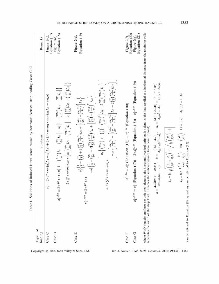
TableI.
Solutionsofinducedlateralstress
causedbyhorizontal/verticalstriploadingCasesC–G.
Type
of
loading
Solutions
Rem
arks
Case
Csu h¼
2*Ps*n*ðu
2 1I c1�
u2 2I c2Þþ
2*Q
s*n*m
1*m
2*ðu
1I d
1�
u2I d
2Þ
Figure
2(c),
Equation(17)
Case
Dsu
lin
h¼2*P
s*n*
u2 11�
u1z b I d
1�
a bI c1
hi �
u2 21�
u2z b I d
2�
a bI c2
hi
no
�2*Q
s*n*m
1*m
2*
u1
a bI d
1�
u1z b I c
1
hi �
u2
a bI d
2�
u2z b I c
2
hi
no
Figure
2(d),
Equation(18)
Case
E
sunon
h¼2*P
s*n*
u2 1
1 2�
a bþ2
a bu1z b I d
1þ
a b 2�
u1z
b 2
�� I c
1
��
�u2 2
1 2�
a bþ
2a b
u2z b I d
2þ
a b 2�
u2z
b 2
�� I c
2
��
2 6 6 6 43 7 7 7 5
þ2*Q
s*n*m
1*m
2*
u1
u1z
b þ
a b 2�
u1z
b 2
�� I d
1�
2a b
u1z b I c
1
��
�u2
u2z
b þ
a b 2�
u2z
b 2
�� I d
2�
2a b
u2z
b I c
2
��
2 6 6 6 43 7 7 7 5
Figure
2(e),
Equation(19)
Case
Fsd
lin
h¼
su hðE
quationð17ÞÞ�
sulin
hðE
quationð18ÞÞ
Figure
2(f),
Equation(20)
Case
Gsd
non
h¼
su hðE
quationð17ÞÞ�2*su
lin
hðEquationð18ÞÞþ
sunon
hðE
quationð19ÞÞ
Figure
2(g),
Equation(21)
wherePs =Q
s(m
axim
um
forceper
unitarea)denotesthehorizontal/verticalstripload;adenotestheloadapplied
atahorizontaldistance
from
theretainingwall;
bdenotesthewidth
ofthestripload;zdenotestheverticaldistance
from
pointto
load;
n¼
A44kðm
2u1�
m1u2Þ
pm1m
2ðu
1�
u2Þ;
k¼ðA
13þ
A44Þ
A33A
44ðu
2 1�u2 2Þ;
mj¼ðA
13þ
A44Þu
j
A33u2 j�A
44
¼A
11�A
44u2 j
ðA13þA
44Þu
j
I cj¼
ln
ffiffiffiffiffiffiffiffiffiffiffiffiffiffiffiffi
ffiffiffiffiffiffiffiffiffiffiffiffiffiffiffiffi
a ujzþ
b ujz
�� 2 þ
1
s� � � � � �,
ffiffiffiffiffiffiffiffiffiffiffiffiffiffiffiffi
ffiffiffiffiffia ujz�� 2 þ
1
s� � � � � �
I dj¼
tan�1
a ujzþ
b ujz
�� �
tan�1
a ujz��ðj¼
1;2Þ;
Aijði;j¼
126Þ
canbereferred
toEquation(9);u1andu2canbereferred
toEquation(12).
Copyright # 2005 John Wiley & Sons, Ltd. Int. J. Numer. Anal. Meth. Geomech. 2005; 29:1341–1361
SURCHARGE STRIP LOADS ON A CROSS-ANISOTROPIC BACKFILL 1353

Figure 5. Flow chart for computing the lateral stress caused by the presented loading casesusing the calculation charts.
Table II. Elastic properties and root type for the isotropic andcross-anisotropic backfills ðE ¼ 50 MPa; n ¼ 0:3Þ:
Soil type E=E0 n=n0 G=G0 Root type
Soil 1. Isotropy 1.0 1.0 1.0 EqualSoil 2. Cross-anisotropy 0.2 1.0 1.0 DistinctSoil 3. Cross-anisotropy 2 1.0 1.0 Complex
Copyright # 2005 John Wiley & Sons, Ltd. Int. J. Numer. Anal. Meth. Geomech. 2005; 29:1341–1361
C.-D. WANG1354

linear-varying strip load (Figure 7(b)) and a vertical upward nonlinear-varying strip load(Figure 7(c)) approaches 0.4416, with increasing a=b from 0 to 10. The magnitude of the ratioinduced by each vertical strip load is within 0.6, except for Figure 7(a) with z=b ¼ 1 and 2, andFigures 7(b) and (c) with z=b ¼ 2 case. Figures 6 and 7 indicate that the lateral stress in thecross-anisotropic backfill (Soil 2) is nearly less than that in the isotropic one (Soil 1), when bothbackfills result from horizontal and vertical strip loads.
0 1 2 3 4 5 6 7 8 9 100.86
0.88
0.9
0.92
0.94
0.96
0.98
1R
atio
ofan
isot
ropi
cto
isot
ropi
cla
tera
lstr
ess
Effect of z/b for E/E'=0.2 (ν/ν'=G/G'=1)induced by a horizontal uniform strip load
z/b=0
z/b=0.1
z/b=0.5
z/b=1
z/b=2
0 1 2 3 4 5 6 7 8 9 100.86
0.88
0.9
0.92
0.94
0.96
0.98
1
Rat
ioof
anis
otro
pic
tois
otro
pic
late
rals
tres
s
Effect of z/b for E/E'=0.2 (ν/ν'=G/G'=1)induced by a horizontal upward linear-varying strip load
z/b=0
z/b=0.1
z/b=0.5
z/b=1
z/b=2
0 1 2 3 4 5 6 7 8 9 10
ab
ab
ab
0.86
0.88
0.9
0.92
0.94
0.96
0.98
1
Rat
ioof
anis
otro
pic
tois
otro
pic
late
rals
tres
s
Effect of z/b for E/E'=0.2 (ν/ν'=G/G'=1)induced by a horizontal upward nonlinear-varying strip load
z/b=0
z/b=0.1
z/b=0.5
z/b=1
z/b=2
(a) (b)
(c)
Figure 6. Effect of z/b: Variation of ratio of anisotropic to isotropic lateral stress forSoil 2: (a) horizontal uniform strip load; (b) horizontal upward linear-varying strip load;
and (c) horizontal upward nonlinear-varying strip load.
Copyright # 2005 John Wiley & Sons, Ltd. Int. J. Numer. Anal. Meth. Geomech. 2005; 29:1341–1361
SURCHARGE STRIP LOADS ON A CROSS-ANISOTROPIC BACKFILL 1355

Figures 8(a)–(c) and 9(a)–(c) illustrate the ratio of anisotropic to isotropic lateral stress (Soil3/Soil 1) for the backfills subjected to the horizontal and vertical strip loads, respectively. Thesegraphs show that as a/b rises from 0 to 10, the ratio reaches 0.9782 (Figures 8(a)–(c)) and 1.313(Figures 9(a)–(c)), when the media are induced by a horizontal/vertical uniform strip load(Figure 8(a)/Figure 9(a)), a horizontal/vertical upward linear-varying strip load (Figure 8(b)/Figure 9(b)) and a horizontal/vertical upward nonlinear-varying strip load (Figure 8(c)/Figure9(c)). Figures 8(a)–(c) for Soil 3 exhibit trends which are distinct from those in Figures 6(a)–(c)
(a) (b)
(c)
0 1 2 3 4 5 6 7 8 9 10
ab
0.4
0.44
0.48
0.52
0.56
0.6R
atio
ofan
isot
ropi
cto
isot
ropi
cla
tera
lstr
ess
Effect of z/b for E/E'=0.2 (ν/ν'=G/G'=1)induced by a vertical uniform strip load
z/b=0
z/b=0.1
z/b=0.5
z/b=1
z/b=2
0 1 2 3 4 5 6 7 8 9 100.4
0.44
0.48
0.52
0.56
0.6
Rat
ioof
anis
otro
pic
tois
otro
pic
late
rals
tres
s
ab
Effect of z/b for E/E'=0.2 (ν/ν'=G/G'=1)induced by a vertical upward linear-varying strip load
z/b=0
z/b=0.1
z/b=0.5
z/b=1
z/b=2
0 1 2 3 4 5 6 7 8 9 10
ab
0.4
0.44
0.48
0.52
0.56
0.6
Rat
ioof
anis
otro
pic
tois
otro
pic
late
rals
tres
s
Effect of z/b for E/E'=0.2 (ν/ν'=G/G'=1)induced by a vertical upward nonlinear-varying strip load
z/b=0
z/b=0.1
z/b=0.5
z/b=1
z/b=2
Figure 7. Effect of z/b: Variation of ratio of anisotropic to isotropic lateral stress forSoil 2: (a) vertical uniform strip load; (b) vertical upward linear-varying strip load; and
(c) vertical upward nonlinear-varying strip load.
Copyright # 2005 John Wiley & Sons, Ltd. Int. J. Numer. Anal. Meth. Geomech. 2005; 29:1341–1361
C.-D. WANG1356
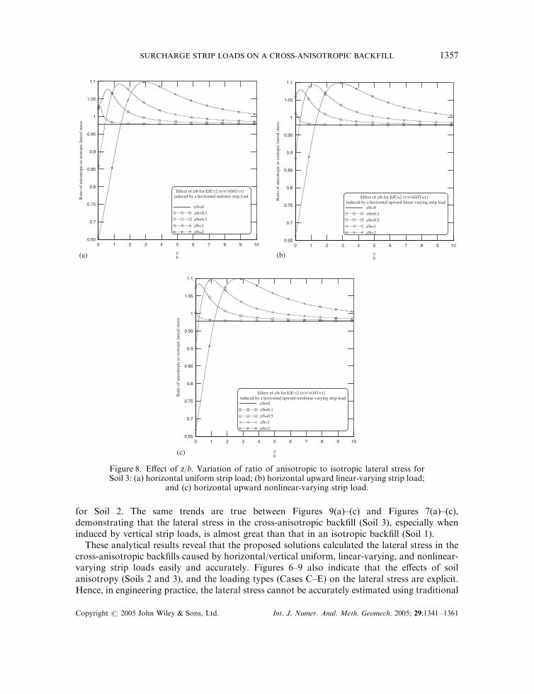
for Soil 2. The same trends are true between Figures 9(a)–(c) and Figures 7(a)–(c),demonstrating that the lateral stress in the cross-anisotropic backfill (Soil 3), especially wheninduced by vertical strip loads, is almost great than that in an isotropic backfill (Soil 1).
These analytical results reveal that the proposed solutions calculated the lateral stress in thecross-anisotropic backfills caused by horizontal/vertical uniform, linear-varying, and nonlinear-varying strip loads easily and accurately. Figures 6–9 also indicate that the effects of soilanisotropy (Soils 2 and 3), and the loading types (Cases C–E) on the lateral stress are explicit.Hence, in engineering practice, the lateral stress cannot be accurately estimated using traditional
(a) (b)
(c)
0 1 2 3 4 5 6 7 8 9 10
ab
0.65
0.7
0.75
0.8
0.85
0.9
0.95
1
1.05
1.1R
atio
ofan
isot
ropi
cto
isot
ropi
cla
tera
lstr
ess
Effect of z/b for E/E'=2 (ν/ν'=G/G'=1)induced by a horizontal uniform strip load
z/b=0
z/b=0.1
z/b=0.5
z/b=1
z/b=2
0 1 2 3 4 5 6 7 8 9 10
ab
0.65
0.7
0.75
0.8
0.85
0.9
0.95
1
1.05
1.1
Rat
ioof
anis
otro
pic
tois
otro
pic
late
rals
tres
s
Effect of z/b for E/E'=2 (ν/ν'=G/G'=1)induced by a horizontal upward linear-varying strip load
z/b=0
z/b=0.1
z/b=0.5
z/b=1
z/b=2
0 1 2 3 4 5 6 7 8 9 10
ab
0.65
0.7
0.75
0.8
0.85
0.9
0.95
1
1.05
1.1
Rat
ioof
anis
otro
pic
tois
otro
pic
late
rals
tres
s
Effect of z/b for E/E'=2 (ν/ν'=G/G'=1)induced by a horizontal upward nonlinear-varying strip load
z/b=0
z/b=0.1
z/b=0.5
z/b=1
z/b=2
Figure 8. Effect of z/b: Variation of ratio of anisotropic to isotropic lateral stress forSoil 3: (a) horizontal uniform strip load; (b) horizontal upward linear-varying strip load;
and (c) horizontal upward nonlinear-varying strip load.
Copyright # 2005 John Wiley & Sons, Ltd. Int. J. Numer. Anal. Meth. Geomech. 2005; 29:1341–1361
SURCHARGE STRIP LOADS ON A CROSS-ANISOTROPIC BACKFILL 1357

isotropic solutions, or by assuming that the surcharge strip load is uniformly distributed on across-anisotropic backfill.
CONCLUSIONS
Integrating the point load solution in a Cartesian co-ordinate system yields the analyticalsolutions for lateral stress caused by horizontal and vertical surcharge strip loads acting on a
(a) (b)
(c)
0 1 2 3 4 5 6 7 8 9 10
ab
0.85
0.9
0.95
1
1.05
1.1
1.15
1.2
1.25
1.3
1.35
1.4
1.45
1.5R
atio
ofan
isot
ropi
cto
isot
ropi
cla
tera
lstr
ess
Effect of z/b for E/E'=2 (ν/ν'=G/G'=1)induced by a vertical uniform strip load
z/b=0
z/b=0.1
z/b=0.5
z/b=1
z/b=2
0 1 2 3 4 5 6 7 8 9 10
ab
0.85
0.9
0.95
1
1.05
1.1
1.15
1.2
1.25
1.3
1.35
1.4
1.45
1.5
Rat
ioof
anis
otro
pic
tois
otro
pic
late
rals
tres
s
Effect of z/b for E/E'=2 (ν/ν'=G/G'=1)induced by a vertical upward linear-varying strip load
z/b=0
z/b=0.1
z/b=0.5
z/b=1
z/b=2
0 1 2 3 4 5 6 7 8 9 10
ab
0.85
0.9
0.95
1
1.05
1.1
1.15
1.2
1.25
1.3
1.35
1.4
1.45
1.5
Rat
ioof
anis
otro
pic
tois
otro
pic
late
rals
tres
s
Effect of z/b for E/E'=2 (ν/ν'=G/G'=1)induced by a vertical upward nonlinear-varying strip load
z/b=0
z/b=0.1
z/b=0.5
z/b=1
z/b=2
Figure 9. Effect of z/b: Variation of ratio of anisotropic to isotropic lateral stress forSoil 3: (a) vertical uniform strip load; (b) vertical upward linear-varying strip load; and
(c) vertical upward nonlinear-varying strip load.
Copyright # 2005 John Wiley & Sons, Ltd. Int. J. Numer. Anal. Meth. Geomech. 2005; 29:1341–1361
C.-D. WANG1358

cross-anisotropic backfill. The cross-anisotropic planes in this study are assumed to be parallelto the horizontal surface of the backfill. The surcharge loading types employed are horizontal/vertical point load, horizontal/vertical line load, horizontal/vertical uniform strip load,horizontal/vertical upward linear-varying strip load, horizontal/vertical upward nonlinear-varying strip load, horizontal/vertical downward linear-varying strip load and horizontal/vertical downward nonlinear-varying strip load. The presented stress solutions are significantlyinfluenced by the type and degree of material anisotropy, and by the horizontal/vertical loadingtypes. Furthermore, this work proposes two calculation charts to calculate the lateral stressinduced by the presented horizontal/vertical strip loads if computers or calculators areunavailable. These charts are appropriate for cross-anisotropic backfills with two real distinctroots of the characteristic equation. The following conclusions can be drawn from the analyticalresults of a parametric study of two illustrative examples.
1. If the backfill material being Soil 2 ðE=E 0 ¼ 0:2; n=n0 ¼ G=G0 ¼ 1Þ; with a=b increasingfrom 0 to 10, the ratio of anisotropic to isotropic lateral stress induced by horizontal andvertical strip loads, respectively, approaches 0.9506 and 0.4416.
2. Figures 6 and 7 show that the lateral stress caused by horizontal and vertical strip loads inSoil 2’s backfill is nearly less than that in the isotropic backfill (Soil 1).
3. If the backfill material is Soil 3 ðE=E0 ¼ 2; n=n0 ¼ G=G0 ¼ 1Þ; then with a=b increasingfrom 0 to 10, the ratio of anisotropic to isotropic lateral stress induced by horizontal andvertical strip loads, respectively, approaches 0.9782 and 1.313.
4. Figures 8 and 9 demonstrate that the lateral stress, particularly when caused by verticalstrip loads in the Soil 3’s backfill, is great than that of the isotropic backfill (Soil 1).
5. Figures 6–9 reveal that the effects of soil anisotropy (Soils 2 and 3) and the loading types(Cases C–E) on the lateral stress are explicit.
The solutions proposed herein can realistically simulate actual surcharge loadingcircumstances in many engineering practices. Moreover, the lateral stress resulting from anyconceivable surcharge strip load can be analysed by superposing the presented loading cases.Regarding the expressions for the location of the centroid of total lateral stress and for the pointof maximum unit lateral stress also can be obtained by integration. Similarly, this article can beextended to derive the lateral stress due to loading perpendicular to the retaining wall. Besides,the impact of the regular/irregular area loads of finite length [37, 38], or of a reinforced cross-anisotropic earth wall system subjected to the action of horizontal and vertical surcharge loads,can also be explored. The results of these investigations will be presented in forthcoming articles.
APPENDIX A: NOMENCLATURE
a load applied at a horizontal distance from the retaining wallAij ði; j ¼ 126Þ elastic moduli or elasticity constantsb width of the strip loaddx infinitesimal element along the x-axisdy infinitesimal element along the y-axisE Young’s modulus in the horizontal directionE0 Young’s modulus in the vertical directionG0 shear modulus in the vertical plane
Copyright # 2005 John Wiley & Sons, Ltd. Int. J. Numer. Anal. Meth. Geomech. 2005; 29:1341–1361
SURCHARGE STRIP LOADS ON A CROSS-ANISOTROPIC BACKFILL 1359

H height of the retaining walli complex number ð¼
ffiffiffiffiffiffiffi�1
pÞ
k;m1;m2; n coefficientsP a horizontal point load (force)Pl a horizontal line load (force per unit length)Ps the horizontal uniform strip load, and the maximum horizontal upward/
downward linear-varying, and nonlinear-varying strip loads (force per unitarea)
Q a vertical point load (force)Ql a vertical line load (force per unit length)Qs the vertical uniform strip load, and the maximum vertical upward/
downward linear-varying, and nonlinear-varying strip loads (force per unitarea)
s; t coefficientsu1; u2; u3 roots of the characteristic equationz vertical distance from point to load
Greek letters
n Poisson’s ratio for the effect of horizontal stress on complementaryhorizontal strain
n0 Poisson’s ratio for the effect of vertical stress on horizontal strainsd linh lateral stress caused by a horizontal/vertical downward linear-varying strip
loadsd nonh lateral stress caused by a horizontal/vertical downward nonlinear-varying
strip loadslh lateral stress caused by a horizontal/vertical line loadsph lateral stress caused by a horizontal/vertical point loadsuh lateral stress caused by a horizontal/vertical uniform strip loadsu linh lateral stress caused by a horizontal/vertical upward linear-varying strip
loadsu nonh lateral stress caused by a horizontal/vertical upward nonlinear-varying strip
load
ACKNOWLEDGEMENTS
The author would like to thank Wan-Ling Chen and Ya-Ting Lin of National United University for theirassistance.
REFERENCES
1. Spangler MG. Lateral pressures on retaining walls caused by superimposed loads. Proceeding of the 18th AnnualMeeting of the Highway Research Board, 1938; 57–65.
2. Sowers GF. Introductory Soil Engineering and Foundations: Geotechnical Engineering (4th edn). MacmillanPublishing Co. Inc.: New York, 1979.
3. Georgiadis M, Anagnostopoulos C. Lateral pressure on sheet pile walls due to strip load. Journal of Geotechnical andGeoenvironmental Engineering (ASCE) 1998; 124(1):95–98.
Copyright # 2005 John Wiley & Sons, Ltd. Int. J. Numer. Anal. Meth. Geomech. 2005; 29:1341–1361
C.-D. WANG1360

4. Spangler MG, Mickle JL. Lateral pressure on retaining walls due to backfill surface loads. Highway Research Board1956; 141.
5. Motta E. Generalized Coulomb active-earth pressure for distanced surcharge. Journal of Geotechnical Engineering(ASCE) 1994; 120(6):1072–1079.
6. Caltabiano S, Cascone E, Maugeri M. Seismic stability of retaining walls with surcharge. Soil Dynamics andEarthquake Engineering 2000; 20(5–8):469–476.
7. Poulos HG, Davis EH. Elastic Solutions for Soil and Rock Mechanics. Wiley; New York, 1974.8. Clayton CRI, Milititsky J, Woods RI. Earth Pressure and Earth-retaining Structures (2nd edn). Chapman & Hall:
New York, 1993.9. Michell JH. The stress in an aeisotropic elastic solid with an infinite plane boundary. Proceedings of the London
Mathematical Society 1900; 32:247–258.10. Barden L. Stresses and displacements in a cross-anisotropic soil. Geotechnique 1963; 13(3):198–210.11. Pickering DJ. Anisotropic elastic parameters for soil. Geotechnique 1970; 20(3):271–276.12. Gerrard CM, Wardle LJ. Solutions for point loads and generalized circular loads applied to a cross-anisotropic half
space. CSIRO Technical Paper 13, 1973; 1–39.13. Gibson RE. The analytical method in soil mechanics. Geotechnique 1974; 24(2):115–140.14. Gazetas G. Stresses and displacements in cross-anisotropic soils. Journal of Geotechnical Engineering Division
(ASCE) 1982; 108(GT4):532–553.15. Wang CD. Displacements and stresses due to vertical subsurface loading for cross-anisotropic half-spaces. Soils and
Foundations 2003; 43(5):40–52.16. Abelev AV, Lade PV. Characterization of failure in cross-anisotropic soils. Journal of Engineering Mechanics
(ASCE) 2004; 130(5):599–606.17. Bowles JE. Foundation Analysis and Design (5th edn). McGraw-Hill Book Company: New York, 1996.18. Boussinesq J. Application des Potentiels a L’Etude de L’Equilibre et due Mouvement des Solides Elastiques. Gauthier-
Villars: Paris, 1885.19. Spangler MG. The distribution of normal pressure on a retaining wall due to a concentrated surface load.
Proceedings of the International Conference on Soil Mechanics and Foundation Engineering, vol. I, 1936; 200–207.20. Spangler MG. Horizontal pressures on retaining walls due to concentrated surface loads. Iowa Engineering
Experiment Station. Bulletin 140, 1938.21. Spangler MG, Handy RL. Soil Engineering (4th edn). Harper & Row Publishers Inc.: New York, 1982.22. Rehnman SE, Broms BB. Lateral pressures on basement wall: results from full-scale tests. Proceedings of the 5th
European Conference on Soil Mechanics and Foundation Engineering, vol. 1, 1972; 189–197.23. Mindlin RD. Pressure distributions on retaining walls. Proceedings of the International Conference on Soil Mechanics
and Foundation Engineering, vol. III, 1936; 155–156.24. Rehnman SE, Broms BB. Lateral pressures on basement wall: results from full-scale tests. Proceedings of the 5th
European Conference on Soil Mechanics and Foundation Engineering, vol. 1, 1972; 189–197.25. Misra B. Lateral pressures on retaining walls due to loads on surface of granular backfill. Soils and Foundations
1980; 20(2):31–44.26. Jarquio R. Total lateral surcharge pressure due to strip load. Journal of Geotechnical Engineering Division (ASCE)
1981; 107(GT10):1424–1428.27. Fang HY. Foundation Engineering Handbook (2nd edn). Chapman & Hall: New York, 1991.28. Wang CD, Liao JJ. Elastic solutions for a transversely isotropic half-space subjected to buried asymmetric-loads.
International Journal for Numerical and Analytical Methods in Geomechanics 1999; 23(2):115–139.29. Liao JJ, Wang CD. Elastic solutions for a transversely isotropic half-space subjected to a point load. International
Journal for Numerical and Analytical Methods in Geomechanics 1998; 22(6):425–447.30. Malmeister AK, Tamuzh VP, Teters GA. Resistance Rigid Polymeric Materials (2nd edn). Zinatne: Riga, 1972.31. Lee KM, Rowe RK. Deformation caused by surface loading and tunneling: the role of elastic anisotropy.
Geotechnique 1989; 39(1):125–140.32. Sutcu M. Orthotropic and transversely isotropic stress–strain relations with built-in coordinate transformations.
International Journal of Solids and Structures 1992; 29(4):503–518.33. Wang CD, Liao JJ. Stress Influence charts for transversely isotropic rocks. International Journal of Rock Mechanics
and Mining Sciences 1998; 35(6):771–785.34. Wang CD, Liao JJ. Computing displacements in transversely isotropic rocks using influence charts. Rock Mechanics
and Rock Engineering 1999; 32(1):51–70.35. Gradshteynn IS, Ryzhik IM. Tables of Integrals, Series, and Products (5th edn). Academic Press: San Diego, 1994.36. Wang CD, Wang WJ, Lee TC. Three-dimensional buried non-linearly varying triangular loads on a transversely
isotropic half-space. International Journal of Solids and Structures 2004; 41(11–12):3013–3030.37. US Army Corps of Engineers. Design of Sheet Pile Walls. ASCE Press: Virginia, 1996.38. Kim JS, Barker RM. Effect of live load surcharge on retaining walls and abutments. Journal of Geotechnical and
Geoenvironment Engineering (ASCE) 2002; 128(10):803–813.
Copyright # 2005 John Wiley & Sons, Ltd. Int. J. Numer. Anal. Meth. Geomech. 2005; 29:1341–1361
SURCHARGE STRIP LOADS ON A CROSS-ANISOTROPIC BACKFILL 1361