laser equipped cnc mills - worcester polytechnic institute · pdf filelaser equipped cnc mills...
TRANSCRIPT
Laser Equipped CNC Mills
Project Number MQP-TSB-AAOZ-21968
DESIGN AND ANALYSIS OF A MECHANICAL SYSTEM TO DO AUTOMATED LASER
MARKING IN A CNC MILL.
A Major Qualifying Project Report
Submitted to the Faculty
of the
Worcester Polytechnic Institute
in partial fulfilment of the requirements for the
Degree of Bachelor of Science
In Mechanical Engineering
By
Edmund C. Resor
___________________________
May 26, 2015
Approved:
________________________
Professor Torbjorn Bergstrom
1. CNC
2. Mechanical System Design
3. Axiomatic Design

i
Abstract
Every year the WPI Manufacturing Laboratories manufactures medallions for Alumni weekend.
The current system requires many valuable man hours to function. Creating an automated system
to laser mark the medallions would improve the current medallion production system. The goal
of this MQP is to use Axiomatic Design to design a mechanical system that would enable
automated laser marking to be done safely inside the CNC Machine tool that finishes the
medallions. Several candidate designs were evaluated based on information content and
uncertainty in their integration and operation. Using a single slide and a galvo laser significantly
reduced the information content of the system. This system will be adequate for marking and
engraving. Thus it has the potential to serve as a starting point for integrating other
manufacturing process, such as additive manufacturing, with CNC milling. This is important
since process integration is becoming increasingly important in the efficient production of
emerging technologies.

ii
Acknowledgements
I would like to thank the following individuals and organizations:
Professors Torborjorn Berstorm and Christopher Brown, for their guidance and support,
especially with the axiomatic decompositions.
Richard Eberhiem, for helping with the electronic side of the project.
Family, for supporting me throughout the project even when it seemed insane.
The staff and other denizens of the Washburn Manufacturing laboratory for help with the varied
aspects of this project.
Automation Direct: for its generous sponsorship: http://www.automationdirect.com/
WPI Mail room services for handling the large number packages this project required.
iii
Table of Contents Page
Abstract ............................................................................................................................................ i
Acknowledgements ......................................................................................................................... ii
List of Figures Page ...................................................................................................................... iv
List of tables Page ...................................................................................................................... iv
1. Introduction ................................................................................................................................. 1
1.1.1 Current process .................................................................................................................. 1
1.1.2 Objective ............................................................................................................................ 1
1.2 Rationale ................................................................................................................................ 2
1.3 State of the Art vs. Current Process ...................................................................................... 2
1.4 Approach ............................................................................................................................... 4
1.5 Method .................................................................................................................................. 5
2. Design Decomposition and Constraints ...................................................................................... 5
2.1 Current Process .................................................................................................................... 5
2.2 Market Ready Options ....................................................................................................... 10
2.3 Custom Design Version 1 .................................................................................................. 12
2.4 Custom Design Version 2 .................................................................................................. 14
3. Design Parameters .................................................................................................................... 16
3.1 Current Process .................................................................................................................. 16
3.2 Market Ready Options ........................................................................................................ 18
3.3. Custom Design Version 1 .................................................................................................. 18
3.4. Custom Design Version 2 .................................................................................................. 19
4. Prototype Production ................................................................................................................ 22
4.1 Demonstration Model .......................................................................................................... 22
4.2 Demonstration Model Parts: Fixtured using a collet chuck ................................................ 23
4.3 Demonstration Model Parts: Fixtured using a vise ............................................................. 23
4.4 Demonstration Model: Tool and Fastener Selection ........................................................... 23
5: Testing with Demonstration Model .......................................................................................... 24
6. A Technically Feasible Method to Automate the Laser Marking of Alumni Medallions ....... 25
6. 1. Major Accomplishments. .................................................................................................. 25
6.2 Design Method .................................................................................................................... 25
6.3 Implications ......................................................................................................................... 25
6.4 Future Work ........................................................................................................................ 25
Concluding Remarks ..................................................................................................................... 26
Works Cited .................................................................................................................................. 27
iv
List of Figures Page
Figure 1 Current process Flow chart 1
Figure 2 Automation of laser marking 2
Figure 3 Current laser marking process 2, 17
Figure 4 AMBIT TM tool changer (Jones J., 2012) 3
Figure 5 BoXZY system (Alec., 2015) 4
Figure 6 Customer Needs for the current process 5
Figure 7 Original process Constraints 5
Figure 8 Current process Decomposition 6
Figure 9 Decomposition of process automation 6
Figure 10 MQP Customer Needs 7
Figure 11 MQP Constraints 7
Figure 12 ABB table 9
Figure 13 MDC dry side 9
Figure 14 MDC wet side 9, 17
Figure 15 AMBIT in operation (Jones, J. 2012) 10
Figure 16 BoXZY being loaded with its 2 watt laser (Alec. 2012) 11
Figure 17 Version 1 FR-DP Decomposition 12
Figure 18 Version 1 model 13
Figure 19 Version 2 model 14
Figure 20 Version 2 FR- DP Decomposition 15
Figure 21 Current process FR-DP coupling Matrix 16
Figure 22 ST-30 SSY 17
Figure 23 Version 1 FR-DP Coupling Matrix 19
Figure 24 Positioning bracket 20
Figure 25 Laser Bracket with galvo scan head 20
Figure 26 A galvo scanner making a test mark at IPG Photonics 21
Figure 27 partial model of the demonstration model 22
Figure 28 Motor mount base, motor mount adapter plate, slide adapter plate 23
List of tables Page
Table 1 Factors in favor of each location for the laser marker 8
Table 2 Factors against each location of the laser marker 8
Table 3 Demonstration Model components being tested 24
1
1. Introduction
1.1.1 Current process
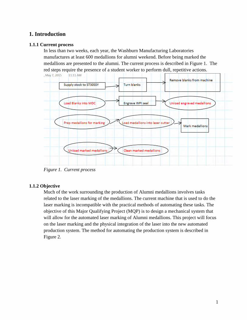
In less than two weeks, each year, the Washburn Manufacturing Laboratories
manufactures at least 600 medallions for alumni weekend. Before being marked the
medallions are presented to the alumni. The current process is described in Figure 1. The
red steps require the presence of a student worker to perform dull, repetitive actions.
Figure 1. Current process
1.1.2 Objective
Much of the work surrounding the production of Alumni medallions involves tasks
related to the laser marking of the medallions. The current machine that is used to do the
laser marking is incompatible with the practical methods of automating these tasks. The
objective of this Major Qualifying Project (MQP) is to design a mechanical system that
will allow for the automated laser marking of Alumni medallions. This project will focus
on the laser marking and the physical integration of the laser into the new automated
production system. The method for automating the production system is described in
Figure 2.
2
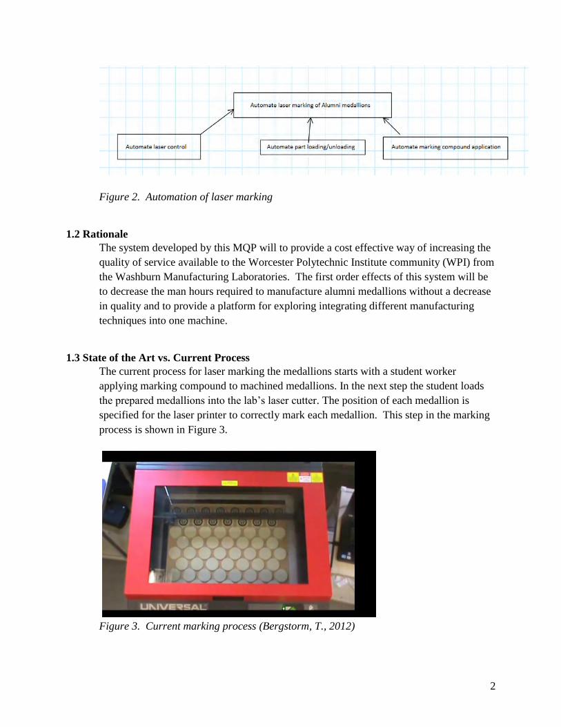
Figure 2. Automation of laser marking
1.2 Rationale
The system developed by this MQP will to provide a cost effective way of increasing the
quality of service available to the Worcester Polytechnic Institute community (WPI) from
the Washburn Manufacturing Laboratories. The first order effects of this system will be
to decrease the man hours required to manufacture alumni medallions without a decrease
in quality and to provide a platform for exploring integrating different manufacturing
techniques into one machine.
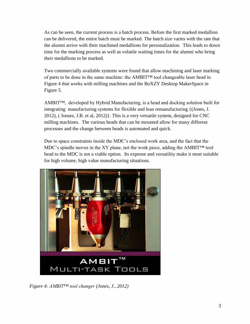
1.3 State of the Art vs. Current Process
The current process for laser marking the medallions starts with a student worker
applying marking compound to machined medallions. In the next step the student loads
the prepared medallions into the lab’s laser cutter. The position of each medallion is
specified for the laser printer to correctly mark each medallion. This step in the marking
process is shown in Figure 3.
Figure 3. Current marking process (Bergstorm, T., 2012)
3
As can be seen, the current process is a batch process. Before the first marked medallion
can be delivered, the entire batch must be marked. The batch size varies with the rate that
the alumni arrive with their machined medallions for personalization. This leads to down
time for the marking process as well as volatile waiting times for the alumni who bring
their medallions to be marked.
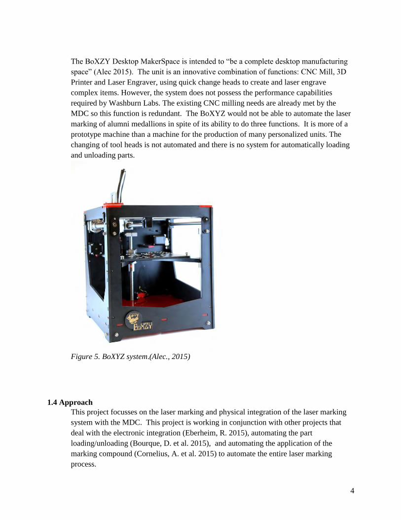
Two commercially available systems were found that allow machining and laser marking
of parts to be done in the same machine: the AMBIT™ tool changeable laser head in
Figure 4 that works with milling machines and the BoXZY Desktop MakerSpace in
Figure 5.
AMBIT™, developed by Hybrid Manufacturing, is a head and docking solution built for
integrating manufacturing systems for flexible and lean remanufacturing (Jones, J.
2012), ( Jonses, J.B. et al, 2012). This is a very versatile system, designed for CNC
milling machines. The various heads that can be mounted allow for many different
processes and the change between heads is automated and quick.
Due to space constraints inside the MDC’s enclosed work area, and the fact that the
MDC’s spindle moves in the XY plane, not the work piece, adding the AMBIT™ tool
head to the MDC is not a viable option. Its expense and versatility make it most suitable
for high volume, high value manufacturing situations.
Figure 4: AMBIT™ tool changer (Jones, J., 2012)
4
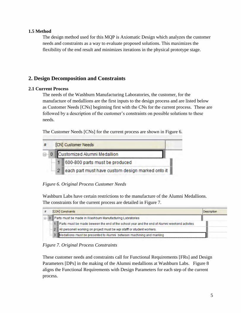
The BoXZY Desktop MakerSpace is intended to “be a complete desktop manufacturing
space” (Alec 2015). The unit is an innovative combination of functions: CNC Mill, 3D
Printer and Laser Engraver, using quick change heads to create and laser engrave
complex items. However, the system does not possess the performance capabilities
required by Washburn Labs. The existing CNC milling needs are already met by the
MDC so this function is redundant. The BoXYZ would not be able to automate the laser
marking of alumni medallions in spite of its ability to do three functions. It is more of a
prototype machine than a machine for the production of many personalized units. The
changing of tool heads is not automated and there is no system for automatically loading
and unloading parts.
Figure 5. BoXYZ system.(Alec., 2015)
1.4 Approach
This project focusses on the laser marking and physical integration of the laser marking
system with the MDC. This project is working in conjunction with other projects that
deal with the electronic integration (Eberheim, R. 2015), automating the part
loading/unloading (Bourque, D. et al. 2015), and automating the application of the
marking compound (Cornelius, A. et al. 2015) to automate the entire laser marking
process.
5
1.5 Method
The design method used for this MQP is Axiomatic Design which analyzes the customer
needs and constraints as a way to evaluate proposed solutions. This maximizes the
flexibility of the end result and minimizes iterations in the physical prototype stage.
2. Design Decomposition and Constraints
2.1 Current Process
The needs of the Washburn Manufacturing Laboratories, the customer, for the
manufacture of medallions are the first inputs to the design process and are listed below
as Customer Needs [CNs] beginning first with the CNs for the current process. These are
followed by a description of the customer’s constraints on possible solutions to these
needs.
The Customer Needs [CNs] for the current process are shown in Figure 6.
Figure 6. Original Process Customer Needs
Washburn Labs have certain restrictions to the manufacture of the Alumni Medallions.
The constraints for the current process are detailed in Figure 7.
Figure 7. Original Process Constraints
These customer needs and constraints call for Functional Requirements [FRs] and Design
Parameters [DPs] in the making of the Alumni medallions at Washburn Labs. Figure 8
aligns the Functional Requirements with Design Parameters for each step of the current
process.
6
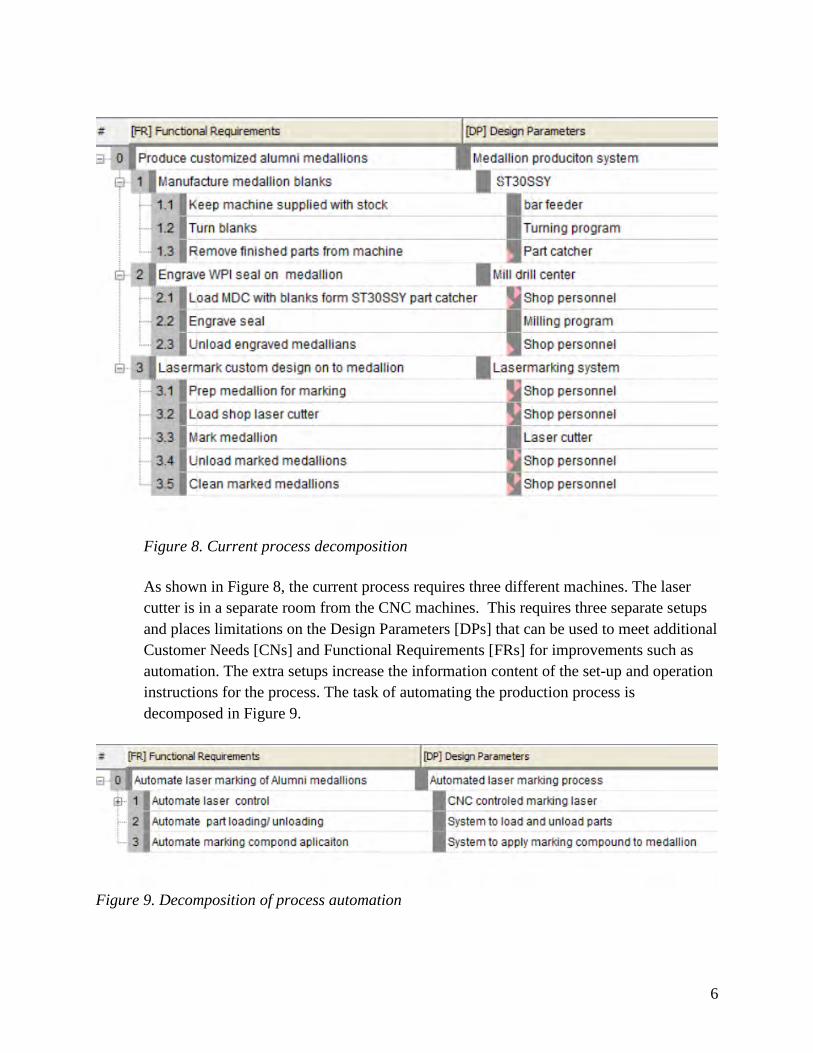
Figure 8. Current process decomposition
As shown in Figure 8, the current process requires three different machines. The laser
cutter is in a separate room from the CNC machines. This requires three separate setups
and places limitations on the Design Parameters [DPs] that can be used to meet additional
Customer Needs [CNs] and Functional Requirements [FRs] for improvements such as
automation. The extra setups increase the information content of the set-up and operation
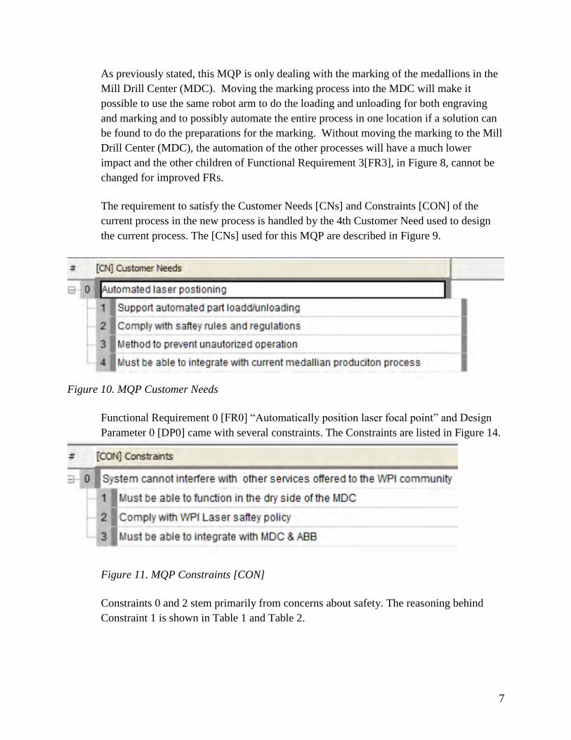
instructions for the process. The task of automating the production process is
decomposed in Figure 9.
Figure 9. Decomposition of process automation
7
As previously stated, this MQP is only dealing with the marking of the medallions in the
Mill Drill Center (MDC). Moving the marking process into the MDC will make it
possible to use the same robot arm to do the loading and unloading for both engraving
and marking and to possibly automate the entire process in one location if a solution can
be found to do the preparations for the marking. Without moving the marking to the Mill
Drill Center (MDC), the automation of the other processes will have a much lower
impact and the other children of Functional Requirement 3[FR3], in Figure 8, cannot be
changed for improved FRs.
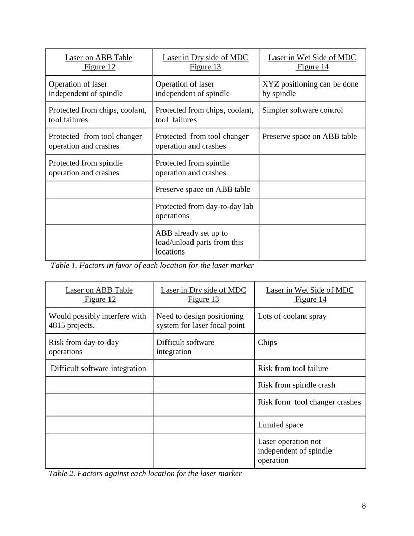
The requirement to satisfy the Customer Needs [CNs] and Constraints [CON] of the
current process in the new process is handled by the 4th Customer Need used to design
the current process. The [CNs] used for this MQP are described in Figure 9.
Figure 10. MQP Customer Needs
Functional Requirement 0 [FR0] “Automatically position laser focal point” and Design
Parameter 0 [DP0] came with several constraints. The Constraints are listed in Figure 14.
Figure 11. MQP Constraints [CON]
Constraints 0 and 2 stem primarily from concerns about safety. The reasoning behind
Constraint 1 is shown in Table 1 and Table 2.
8
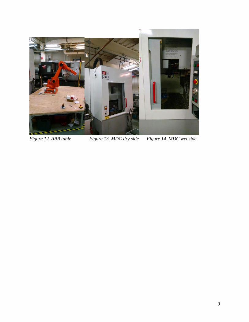
Laser on ABB Table
Figure 12
Laser in Dry side of MDC
Figure 13
Laser in Wet Side of MDC
Figure 14
Operation of laser
independent of spindle
Operation of laser
independent of spindle
XYZ positioning can be done
by spindle
Protected from chips, coolant,
tool failures
Protected from chips, coolant,
tool failures
Simpler software control
Protected from tool changer
operation and crashes
Protected from tool changer
operation and crashes
Preserve space on ABB table
Protected from spindle
operation and crashes
Protected from spindle
operation and crashes
Preserve space on ABB table
Protected from day-to-day lab
operations
ABB already set up to
load/unload parts from this
locations
Table 1. Factors in favor of each location for the laser marker
Laser on ABB Table
Figure 12
Laser in Dry side of MDC
Figure 13
Laser in Wet Side of MDC
Figure 14
Would possibly interfere with
4815 projects.
Need to design positioning
system for laser focal point
Lots of coolant spray
Risk from day-to-day
operations
Difficult software
integration
Chips
Difficult software integration Risk from tool failure
Risk from spindle crash
Risk form tool changer crashes
Limited space
Laser operation not
independent of spindle
operation
Table 2. Factors against each location for the laser marker
9
Figure 12. ABB table Figure 13. MDC dry side Figure 14. MDC wet side
10
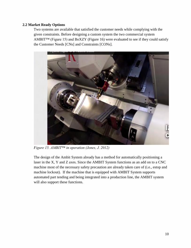
2.2 Market Ready Options
Two systems are available that satisfied the customer needs while complying with the
given constraints. Before designing a custom system the two commercial system
AMBIT™ (Figure 15) and BoXZY (Figure 16) were evaluated to see if they could satisfy
the Customer Needs [CNs] and Constraints [CONs].
Figure 15. AMBIT™ in operation (Jones, J. 2012)
The design of the Ambit System already has a method for automatically positioning a
laser in the X, Y and Z axes. Since the AMBIT System functions as an add on to a CNC
machine most of the necessary safety precaution are already taken care of (i.e., estop and
machine lockout). If the machine that is equipped with AMBIT System supports
automated part tending and being integrated into a production line, the AMBIT system
will also support these functions.
11
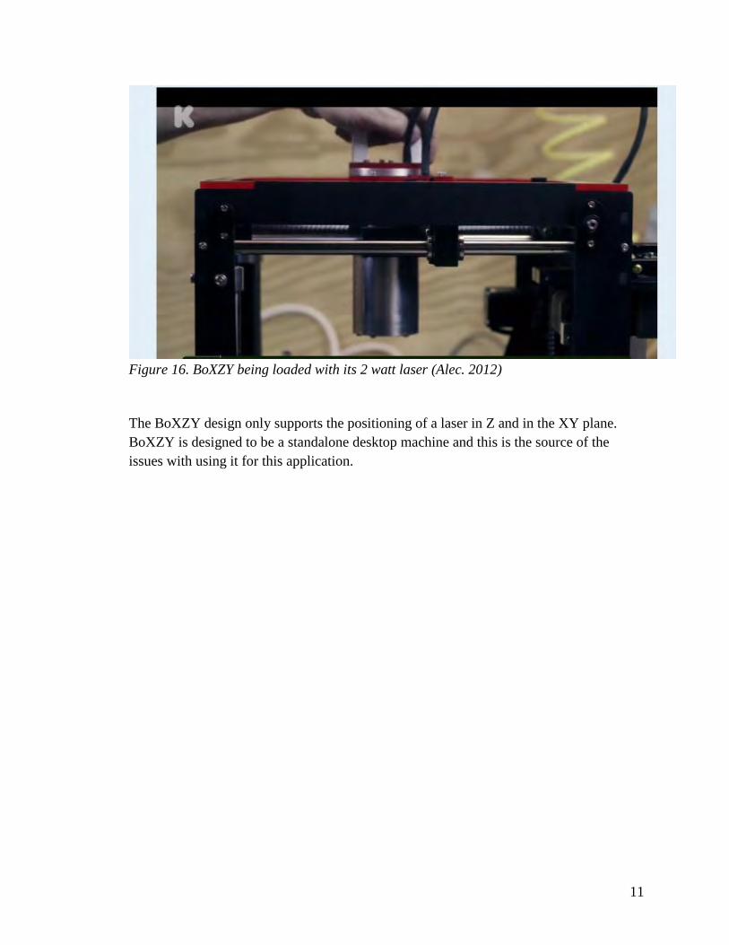
Figure 16. BoXZY being loaded with its 2 watt laser (Alec. 2012)
The BoXZY design only supports the positioning of a laser in Z and in the XY plane.
BoXZY is designed to be a standalone desktop machine and this is the source of the
issues with using it for this application.
12
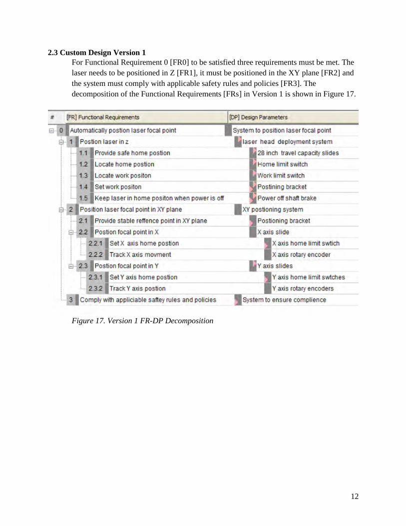
2.3 Custom Design Version 1
For Functional Requirement 0 [FR0] to be satisfied three requirements must be met. The
laser needs to be positioned in Z [FR1], it must be positioned in the XY plane [FR2] and
the system must comply with applicable safety rules and policies [FR3]. The
decomposition of the Functional Requirements [FRs] in Version 1 is shown in Figure 17.
Figure 17. Version 1 FR-DP Decomposition
13
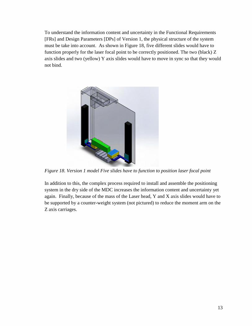
To understand the information content and uncertainty in the Functional Requirements
[FRs] and Design Parameters [DPs] of Version 1, the physical structure of the system
must be take into account. As shown in Figure 18, five different slides would have to
function properly for the laser focal point to be correctly positioned. The two (black) Z
axis slides and two (yellow) Y axis slides would have to move in sync so that they would
not bind.
Figure 18. Version 1 model Five slides have to function to position laser focal point
In addition to this, the complex process required to install and assemble the positioning
system in the dry side of the MDC increases the information content and uncertainty yet
again. Finally, because of the mass of the Laser head, Y and X axis slides would have to
be supported by a counter-weight system (not pictured) to reduce the moment arm on the
Z axis carriages.
14
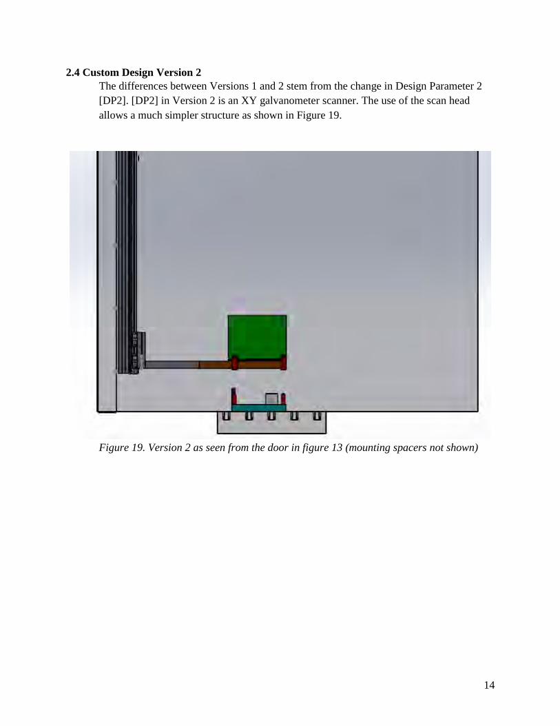
2.4 Custom Design Version 2
The differences between Versions 1 and 2 stem from the change in Design Parameter 2
[DP2]. [DP2] in Version 2 is an XY galvanometer scanner. The use of the scan head
allows a much simpler structure as shown in Figure 19.
Figure 19. Version 2 as seen from the door in figure 13 (mounting spacers not shown)
15
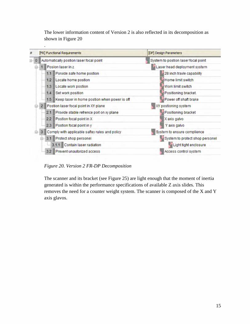
The lower information content of Version 2 is also reflected in its decomposition as
shown in Figure 20
.
Figure 20. Version 2 FR-DP Decomposition
The scanner and its bracket (see Figure 25) are light enough that the moment of inertia
generated is within the performance specifications of available Z axis slides. This
removes the need for a counter weight system. The scanner is composed of the X and Y
axis glavos.
16
3. Design Parameters
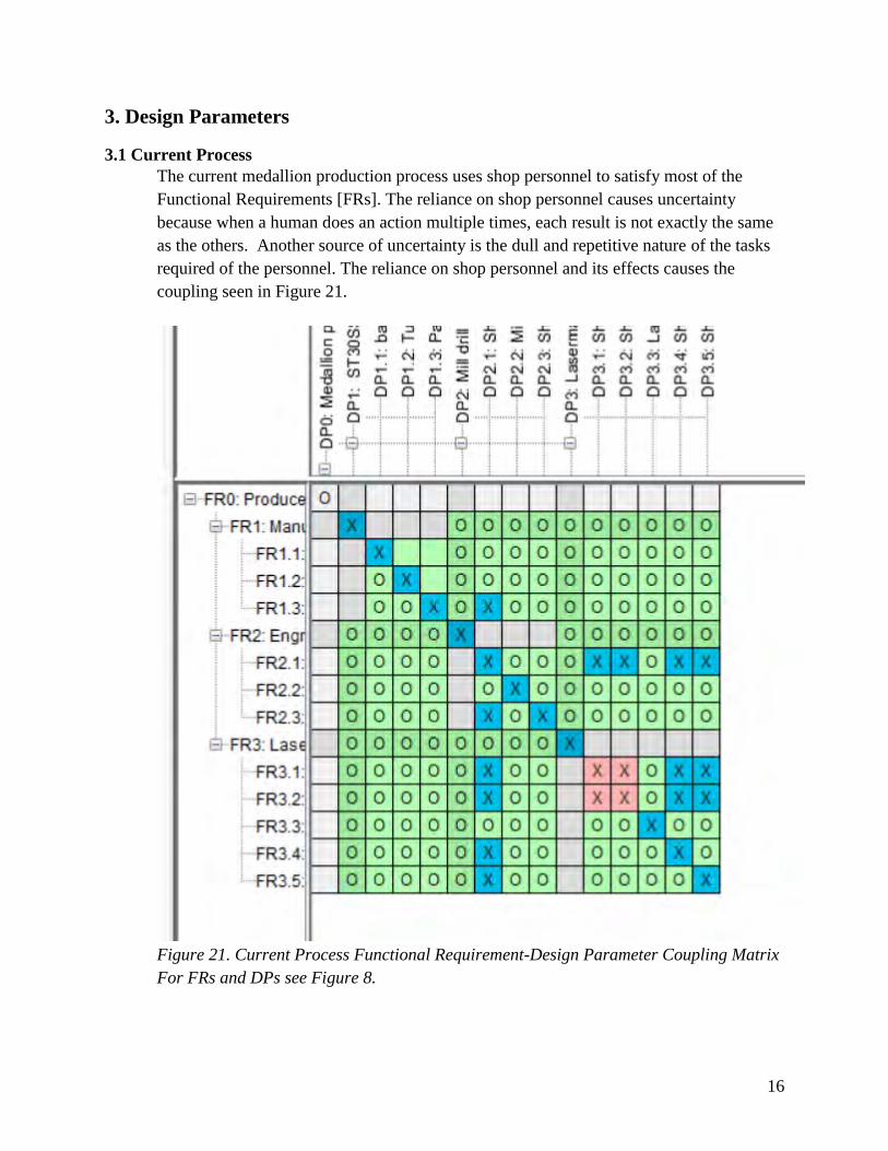
3.1 Current Process
The current medallion production process uses shop personnel to satisfy most of the
Functional Requirements [FRs]. The reliance on shop personnel causes uncertainty
because when a human does an action multiple times, each result is not exactly the same
as the others. Another source of uncertainty is the dull and repetitive nature of the tasks
required of the personnel. The reliance on shop personnel and its effects causes the
coupling seen in Figure 21.
Figure 21. Current Process Functional Requirement-Design Parameter Coupling Matrix
For FRs and DPs see Figure 8.
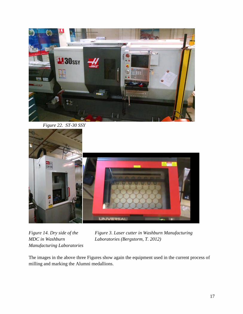
17
Figure 22. ST-30 SSY
Figure 14. Dry side of the Figure 3. Laser cutter in Washburn Manufacturing
MDC in Washburn Laboratories (Bergstorm, T. 2012)
Manufacturing Laboratories
The images in the above three Figures show again the equipment used in the current process of
milling and marking the Alumni medallions.
18
3.2 Market Ready Options
AMBIT™’s use of a tool changeable laser head that uses a machine spindle to perform
the positioning functions is the key to a system's ability to satisfy multiple requirements.
It is also what violates Constraint 1 [CON1]. If Constraint 1 was ignored, the system
would still not be a viable option since beam transport system use would not fit in the wet
side of the Mill Drill Center.
Due to the role that BoXZY was designed to fill, it does not have a way to satisfy the
needs of this project. BoXZY would have to be mounted on the ABB robot table, since it
is designed to sit on a desk, not fixtured to a machine table. The methods of access to the
BoXZY work volume are designed for manual loading and unloading of parts. Modifying
the BoXZY system to work would require an excessive amount of modifications.
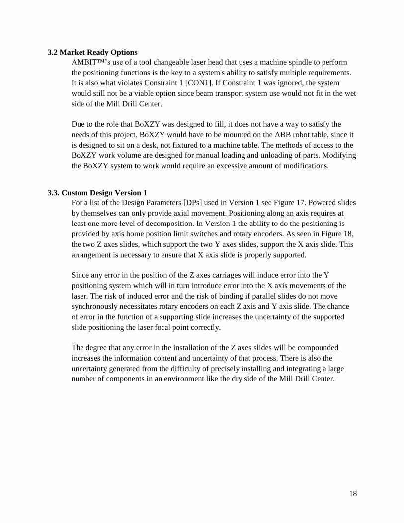
3.3. Custom Design Version 1
For a list of the Design Parameters [DPs] used in Version 1 see Figure 17. Powered slides
by themselves can only provide axial movement. Positioning along an axis requires at
least one more level of decomposition. In Version 1 the ability to do the positioning is
provided by axis home position limit switches and rotary encoders. As seen in Figure 18,
the two Z axes slides, which support the two Y axes slides, support the X axis slide. This
arrangement is necessary to ensure that X axis slide is properly supported.
Since any error in the position of the Z axes carriages will induce error into the Y
positioning system which will in turn introduce error into the X axis movements of the
laser. The risk of induced error and the risk of binding if parallel slides do not move
synchronously necessitates rotary encoders on each Z axis and Y axis slide. The chance
of error in the function of a supporting slide increases the uncertainty of the supported
slide positioning the laser focal point correctly.
The degree that any error in the installation of the Z axes slides will be compounded
increases the information content and uncertainty of that process. There is also the
uncertainty generated from the difficulty of precisely installing and integrating a large
number of components in an environment like the dry side of the Mill Drill Center.
19
Figure 23. Version 1 Functional Requirement-Design Parameter Coupling Matrix
3.4. Custom Design Version 2
For the Design Parameters [DPs] used in Version 2 see Figure 20. The use of a
Galvanometer scanner to do the positioning in the XY plane allows for [DPs] with lower
information content to be used. First the [DPs] positioning the laser focal point in Z are
reduced to a home position limit switch, a work position limit switch, power off shaft
brake and a single Z axis slide. Thus eliminating the information content and uncertainty
from the second Z axis slide and the components needed to ensure the two slides work
synchronously with each other.
20
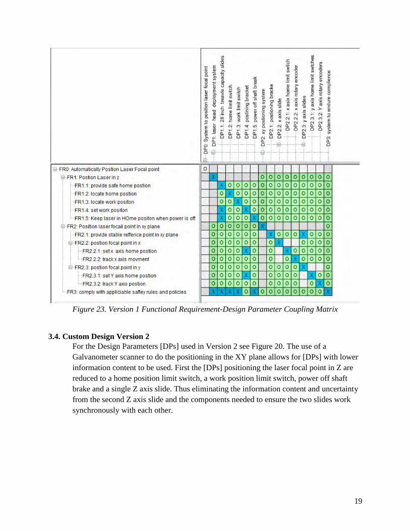
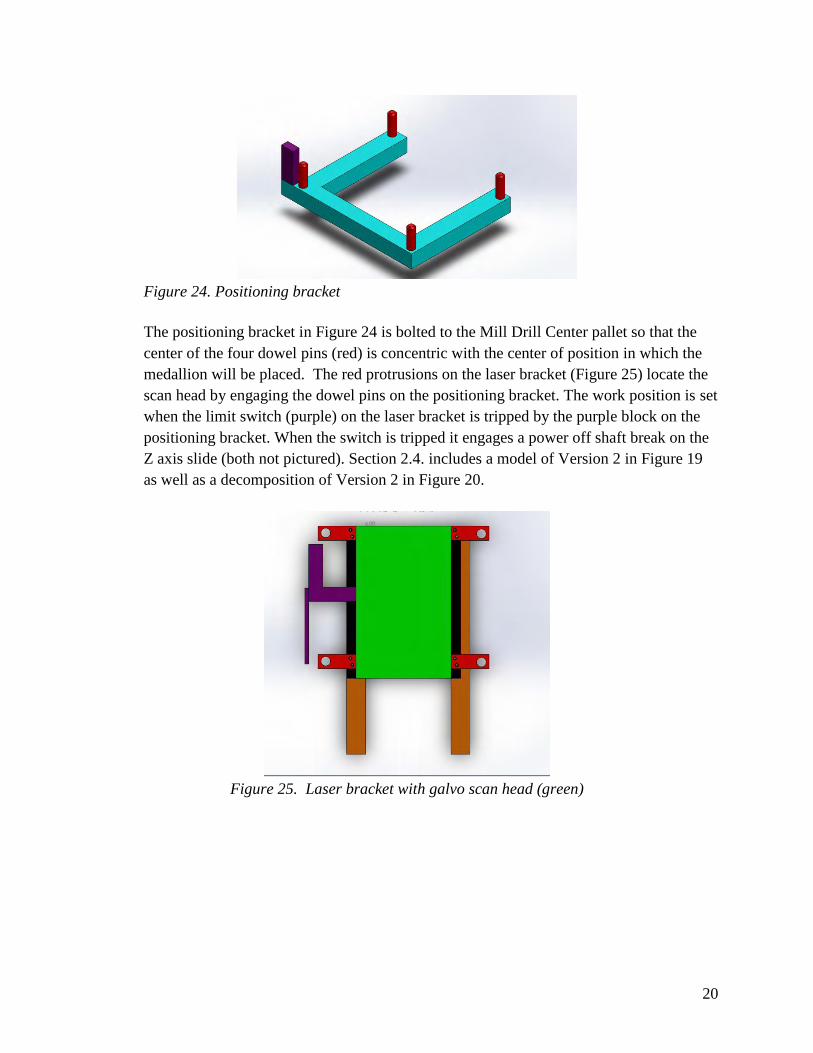
Figure 24. Positioning bracket
The positioning bracket in Figure 24 is bolted to the Mill Drill Center pallet so that the
center of the four dowel pins (red) is concentric with the center of position in which the
medallion will be placed. The red protrusions on the laser bracket (Figure 25) locate the
scan head by engaging the dowel pins on the positioning bracket. The work position is set
when the limit switch (purple) on the laser bracket is tripped by the purple block on the
positioning bracket. When the switch is tripped it engages a power off shaft break on the
Z axis slide (both not pictured). Section 2.4. includes a model of Version 2 in Figure 19
as well as a decomposition of Version 2 in Figure 20.
Figure 25. Laser bracket with galvo scan head (green)
21
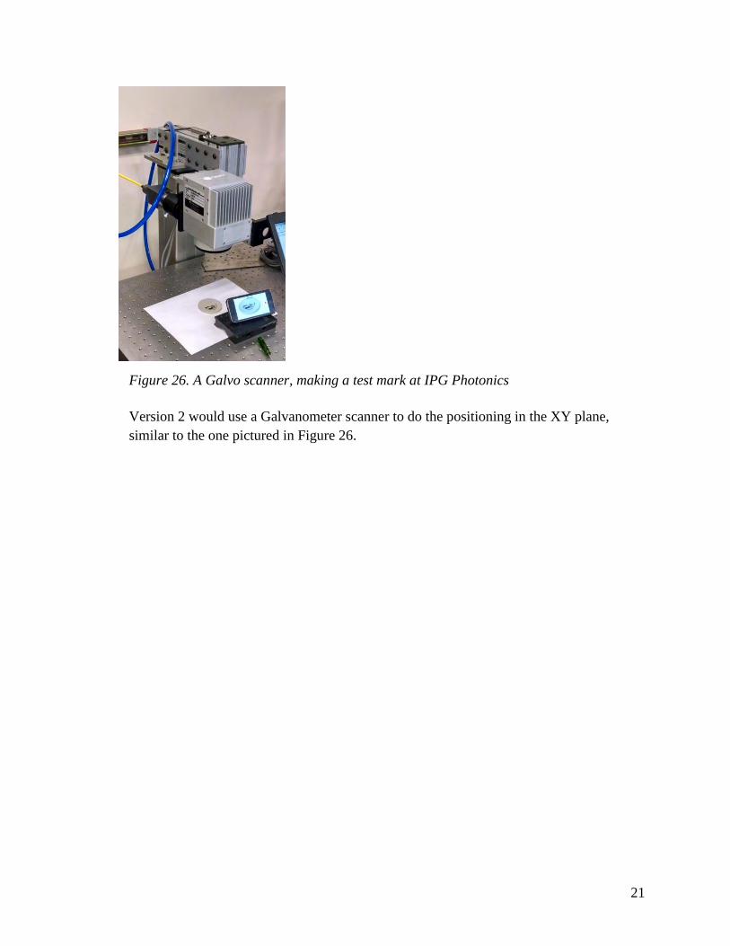
Figure 26. A Galvo scanner, making a test mark at IPG Photonics
Version 2 would use a Galvanometer scanner to do the positioning in the XY plane,
similar to the one pictured in Figure 26.
22
4. Prototype Production
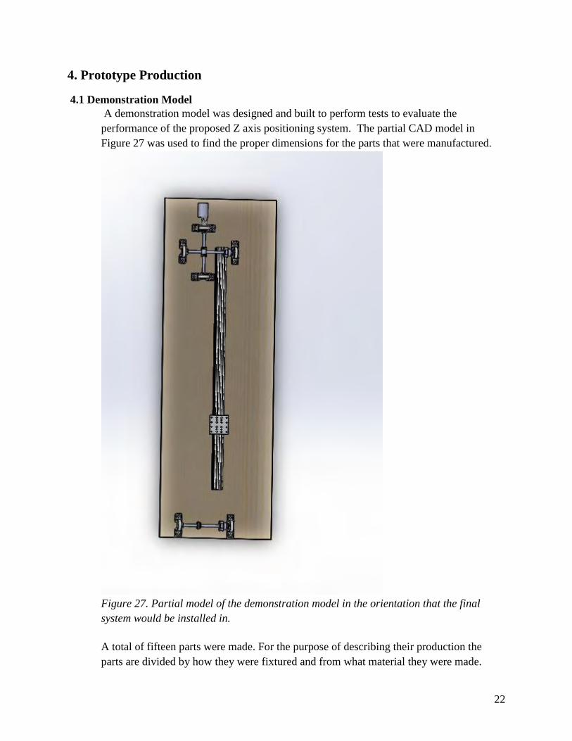
4.1 Demonstration Model
A demonstration model was designed and built to perform tests to evaluate the
performance of the proposed Z axis positioning system. The partial CAD model in
Figure 27 was used to find the proper dimensions for the parts that were manufactured.
Figure 27. Partial model of the demonstration model in the orientation that the final
system would be installed in.
A total of fifteen parts were made. For the purpose of describing their production the
parts are divided by how they were fixtured and from what material they were made.
23
4.2 Demonstration Model Parts: Fixtured using a collet chuck
Twelve of the 15 parts needed were spacers, made from scrap one inch diameter 6061 bar
stock. Each spacer has a 5/16-18” hole on the top and the bottom. Eight of the spacers
were 3.8 inches tall, 12 pieces of bar stock were found to already be the height needed for
the tall spacer, so they were just drilled and tapped on each end. The only difference in
production, the 4 short spacers, was that the stock was faced down to the needed height of
2.2 inches before being drilled and tapped. 6061 Aluminum was chosen for the
availability of scrap stock in a workable shape and the ease of machining it.
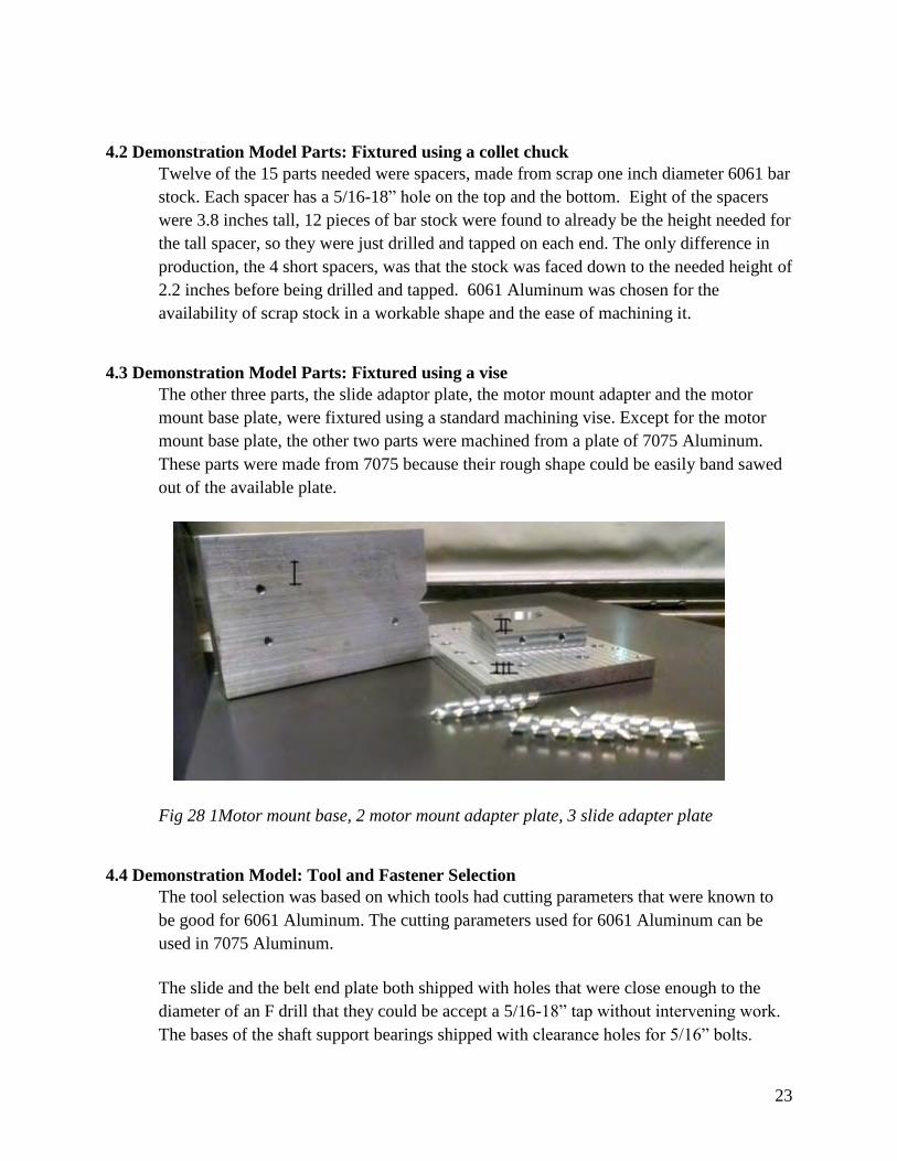
4.3 Demonstration Model Parts: Fixtured using a vise
The other three parts, the slide adaptor plate, the motor mount adapter and the motor
mount base plate, were fixtured using a standard machining vise. Except for the motor
mount base plate, the other two parts were machined from a plate of 7075 Aluminum.
These parts were made from 7075 because their rough shape could be easily band sawed
out of the available plate.
Fig 28 1Motor mount base, 2 motor mount adapter plate, 3 slide adapter plate
4.4 Demonstration Model: Tool and Fastener Selection
The tool selection was based on which tools had cutting parameters that were known to
be good for 6061 Aluminum. The cutting parameters used for 6061 Aluminum can be
used in 7075 Aluminum.
The slide and the belt end plate both shipped with holes that were close enough to the
diameter of an F drill that they could be accept a 5/16-18” tap without intervening work.
The bases of the shaft support bearings shipped with clearance holes for 5/16” bolts.
24
These parts and the spacers were held in place with 5/16-18” bolts. The mounting
hardware for the motor was chosen to be 10-32 bolts since this was the thread size of the
mounting holes on the motor face plate.
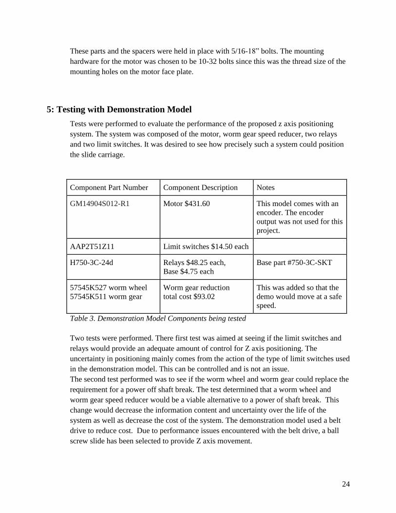
5: Testing with Demonstration Model
Tests were performed to evaluate the performance of the proposed z axis positioning
system. The system was composed of the motor, worm gear speed reducer, two relays
and two limit switches. It was desired to see how precisely such a system could position
the slide carriage.
Component Part Number Component Description Notes
GM14904S012-R1 Motor $431.60 This model comes with an
encoder. The encoder
output was not used for this
project.
AAP2T51Z11 Limit switches $14.50 each
H750-3C-24d Relays $48.25 each,
Base $4.75 each
Base part #750-3C-SKT
57545K527 worm wheel
57545K511 worm gear
Worm gear reduction
total cost $93.02
This was added so that the
demo would move at a safe
speed.
Table 3. Demonstration Model Components being tested
Two tests were performed. There first test was aimed at seeing if the limit switches and
relays would provide an adequate amount of control for Z axis positioning. The
uncertainty in positioning mainly comes from the action of the type of limit switches used
in the demonstration model. This can be controlled and is not an issue.
The second test performed was to see if the worm wheel and worm gear could replace the
requirement for a power off shaft break. The test determined that a worm wheel and
worm gear speed reducer would be a viable alternative to a power of shaft break. This
change would decrease the information content and uncertainty over the life of the
system as well as decrease the cost of the system. The demonstration model used a belt
drive to reduce cost. Due to performance issues encountered with the belt drive, a ball
screw slide has been selected to provide Z axis movement.
25
6. A Technically Feasible Method to Automate the Laser Marking of Alumni
Medallions
6. 1. Major Accomplishments.
The main accomplishment of this MQP was determining a technically feasible method to
automate the laser marking of Alumni medallions. For this accomplishment to happen,
three things had to happen. First, the location of the laser marking system had to be
determined. Second, an automated system that would work in the chosen location had to
be designed. The system designed needed to be able to communicate with the Mill Drill
Center and the ABB robot arm. Two methods for the communication are via commands
serial over RS232 (Eberhiem, R. 2015) or relay based communication (Bourque, D. et
al.).
6.2 Design Method
The design method was sound. The cost of components hindered the implementation
process. The main fault in the design process was that an excessive amount of time was
spent waiting for data from possible venders.
6.3 Implications
This project, if brought to complete implementation, will have significant impact in
multiple areas. The impact of the project will be initially noticed in the man hours saved
in alumni medallion production and value added to the robotic machine tending and
marking compound application projects. While the components needed are expensive, the
payoff will come primarily from the education and research opportunities it will allow
future students to explore, especially since automation and integration are becoming
increasingly important (Vijay, S. 2014).
6.4 Future Work
For the most part, the future work that remains for this project is to see how it performs in
practice. Other future work would be to see if this system could be used to improve any
of the classes offered to the WPI community. What other future work that could be done
depends on how the system performs once it is integrated. For this to happen additional
funding, of approximately $35,000 needs to be secured to purchase the required
components. Except for the laser and the required fiber optic cable all components could
be manufactured in house by student project groups.

26
Concluding Remarks
1. Determined that it is technically feasible to automate the production of alumni
medallions with currently available technology.
2. Axiomatic design is an effective method to use with a large project that needs to
be broken down into smaller subprojects that are tasked to separate groups.
3. The lack of sufficient funding prevented the testing of the fully integrated design.
27
Works Cited
Alec, 2015. BoXZY, an all-in-one 3D printer, CNC mill and laser engraver launches on
Kickstarter. 3ders.Org. Available from: http://www.3ders.org/articles/20150309-boxzy-an-
all-in-one-3d-printer-laser-etcher-cnc-machine-launches-on-kickstarter.html [Accessed
April 20, 2015].
Bergstrom, T., 2012. Reunion Medalions 1, WPI Haas Technical Education Center.
Bourque, D. et al., Machine Tending, Appendix A
Cornelius, A. et al., Automated application of laser marking compound. Appendix B
Eberheim, R., Using Serial Com On The MDC Appendix C
Engineering Laboratory, Systems Integration Division & Vijay, S., 2014. Systems Integration
Division , NIST.
Jones, J., 2012. Hybrid Manufacturing Technologies. Hybrid Manufacturing Technologies.
Available from: http://www.hybridmanutech.com/ [Accessed April 20, 2015].
Jones, J.B. et al. 2012, 23rd Annual International Solid Freeform Fabrication Symposium. In
23rd Annual International Solid Freeform Fabrication Symposium. Austin, TX, pp. 821–
827.
Roberts, L.M., How Laser Shows Work - Scanning Systems - www.LaserFX.com. How Laser
Shows Work . Available from: http://www.laserfx.com/works/works3s.html [Accessed
May 14, 2015].
Vy-teck, 2014. Quote WPI for Edmund vyek contact. Quote WPI For Edmund Vyek Contact
Appendix D

Machine Tending A Class Project for ME/RBE 4815
Group 1:
Don Bourque, David Ephraim
Gabe Isko, Norbert Mongeon
Appendix A - 1 of 17
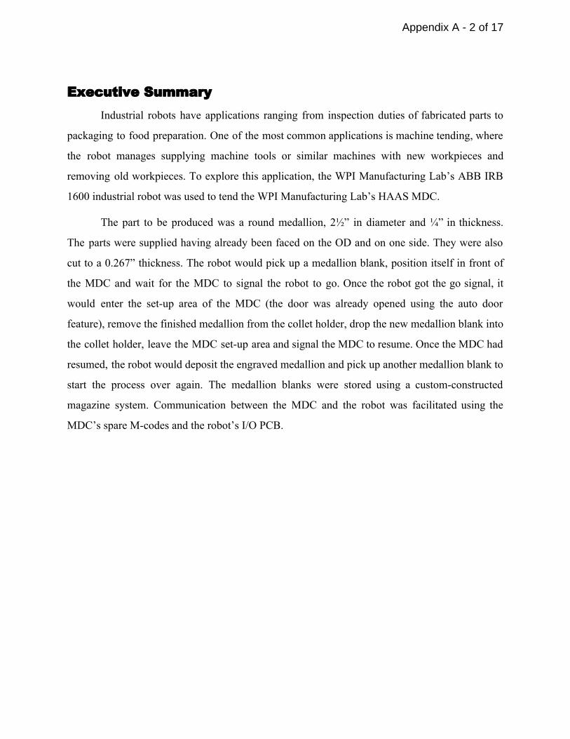
Executive Summary Industrial robots have applications ranging from inspection duties of fabricated parts to
packaging to food preparation. One of the most common applications is machine tending, where
the robot manages supplying machine tools or similar machines with new workpieces and
removing old workpieces. To explore this application, the WPI Manufacturing Lab’s ABB IRB
1600 industrial robot was used to tend the WPI Manufacturing Lab’s HAAS MDC.
The part to be produced was a round medallion, 2½” in diameter and ¼” in thickness.
The parts were supplied having already been faced on the OD and on one side. They were also
cut to a 0.267” thickness. The robot would pick up a medallion blank, position itself in front of
the MDC and wait for the MDC to signal the robot to go. Once the robot got the go signal, it
would enter the setup area of the MDC (the door was already opened using the auto door
feature), remove the finished medallion from the collet holder, drop the new medallion blank into
the collet holder, leave the MDC setup area and signal the MDC to resume. Once the MDC had
resumed, the robot would deposit the engraved medallion and pick up another medallion blank to
start the process over again. The medallion blanks were stored using a customconstructed
magazine system. Communication between the MDC and the robot was facilitated using the
MDC’s spare Mcodes and the robot’s I/O PCB.
Appendix A - 2 of 17

Table of Contents Executive Summary
Introduction
Goal Statement
Task Specifications
Workspace Setup
Gripper Design
Programming
Results and Discussion
Conclusions
Bibliography
Appendix A - 3 of 17
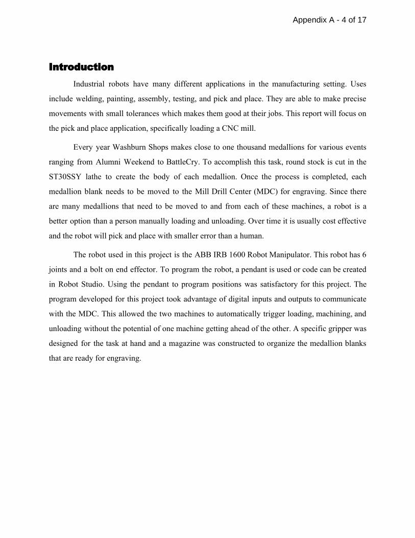
Introduction Industrial robots have many different applications in the manufacturing setting. Uses
include welding, painting, assembly, testing, and pick and place. They are able to make precise
movements with small tolerances which makes them good at their jobs. This report will focus on
the pick and place application, specifically loading a CNC mill.
Every year Washburn Shops makes close to one thousand medallions for various events
ranging from Alumni Weekend to BattleCry. To accomplish this task, round stock is cut in the
ST30SSY lathe to create the body of each medallion. Once the process is completed, each
medallion blank needs to be moved to the Mill Drill Center (MDC) for engraving. Since there
are many medallions that need to be moved to and from each of these machines, a robot is a
better option than a person manually loading and unloading. Over time it is usually cost effective
and the robot will pick and place with smaller error than a human.
The robot used in this project is the ABB IRB 1600 Robot Manipulator. This robot has 6
joints and a bolt on end effector. To program the robot, a pendant is used or code can be created
in Robot Studio. Using the pendant to program positions was satisfactory for this project. The
program developed for this project took advantage of digital inputs and outputs to communicate
with the MDC. This allowed the two machines to automatically trigger loading, machining, and
unloading without the potential of one machine getting ahead of the other. A specific gripper was
designed for the task at hand and a magazine was constructed to organize the medallion blanks
that are ready for engraving.
Appendix A - 4 of 17

Goal Statement It is intended to use the ABB robot arm to load and unload 2 ½” medallion blanks from
the HAAS Mill Drill Center.
Appendix A - 5 of 17
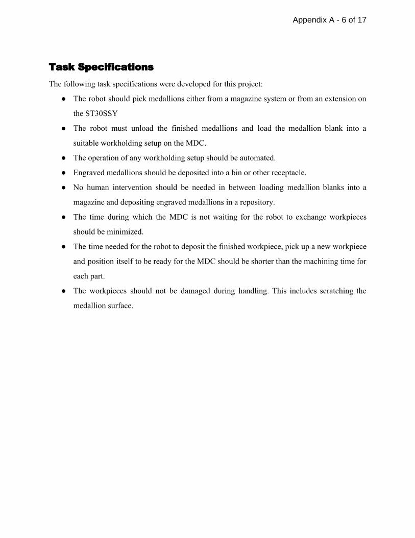
Task Specifications The following task specifications were developed for this project:
The robot should pick medallions either from a magazine system or from an extension on
the ST30SSY
The robot must unload the finished medallions and load the medallion blank into a
suitable workholding setup on the MDC.
The operation of any workholding setup should be automated.
Engraved medallions should be deposited into a bin or other receptacle.
No human intervention should be needed in between loading medallion blanks into a
magazine and depositing engraved medallions in a repository.
The time during which the MDC is not waiting for the robot to exchange workpieces
should be minimized.
The time needed for the robot to deposit the finished workpiece, pick up a new workpiece
and position itself to be ready for the MDC should be shorter than the machining time for
each part.
The workpieces should not be damaged during handling. This includes scratching the
medallion surface.
Appendix A - 6 of 17
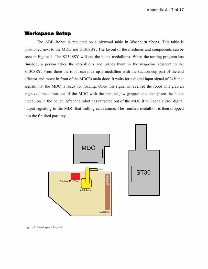
Workspace Setup The ABB Robot is mounted on a plywood table in Washburn Shops. This table is
positioned next to the MDC and ST30SSY. The layout of the machines and components can be
seen in Figure 1. The ST30SSY will cut the blank medallions. When the turning program has
finished, a person takes the medallions and places them in the magazine adjacent to the
ST30SSY. From there the robot can pick up a medallion with the suction cup part of the end
effector and move in front of the MDC’s main door. It waits for a digital input signal of 24V that
signals that the MDC is ready for loading. Once this signal is received the robot will grab an
engraved medallion out of the MDC with the parallel jaw gripper and then place the blank
medallion in the collet. After the robot has retracted out of the MDC it will send a 24V digital
output signaling to the MDC that milling can resume. The finished medallion is then dropped
into the finished part tray.
Figure 1: Workspace Layout
Appendix A - 7 of 17
In order to maneuver in the confined space between machines and other components, a
combination of J and L moves were required. High precision of positions was needed to have
the program run without crashing or misalignment.
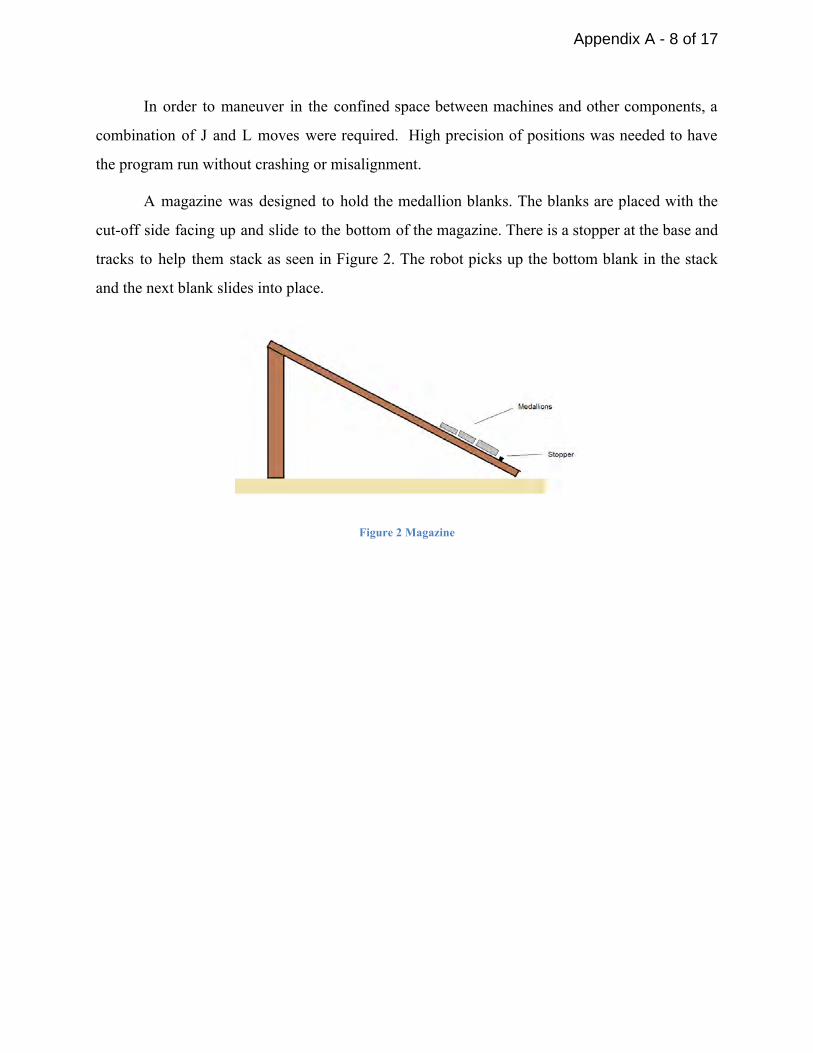
A magazine was designed to hold the medallion blanks. The blanks are placed with the
cutoff side facing up and slide to the bottom of the magazine. There is a stopper at the base and
tracks to help them stack as seen in Figure 2. The robot picks up the bottom blank in the stack
and the next blank slides into place.
Figure 2 Magazine
Appendix A - 8 of 17
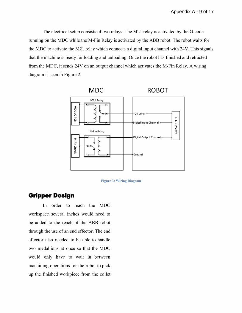
The electrical setup consists of two relays. The M21 relay is activated by the Gcode
running on the MDC while the MFin Relay is activated by the ABB robot. The robot waits for
the MDC to activate the M21 relay which connects a digital input channel with 24V. This signals
that the machine is ready for loading and unloading. Once the robot has finished and retracted
from the MDC, it sends 24V on an output channel which activates the MFin Relay. A wiring
diagram is seen in Figure 2.
Figure 3: Wiring Diagram
Gripper Design In order to reach the MDC
workspace several inches would need to
be added to the reach of the ABB robot
through the use of an end effector. The end
effector also needed to be able to handle
two medallions at once so that the MDC
would only have to wait in between
machining operations for the robot to pick
up the finished workpiece from the collet
Appendix A - 9 of 17
holder and deposit the new workpiece. If the end effector could only handle one workpiece, the
MDC would have to wait for the robot to pick up the finished workpiece from the collet holder,
deposit the finished workpiece in a bin, pick up a new blank workpiece and position the new
workpiece in the collet holder. This would take several times longer than the previous option.
Before designing the end effector, the team set about finding the necessary grippers. A
suction cup gripper was desired for the unengraved blanks while a parallel jaw gripper was
desired for the engraved blanks due to the fact that the engraving would provide leak paths that
would prevent proper operation when used with the suction cup. A suction cup and venturi
vacuum generator that provided the needed performance were available from the supplies for the
ABB robot. A small parallel jaw manipulator with the necessary strength was attached to the
unused FANUC robot arm. Both of these grippers were obtained for this project.
To attach the gripper to the tooling plate, an existing but wrongly fabricated tool
attachment plate was obtained from the robot supplies and fixed to allow for mounting to the
existing tooling plate. To provide the needed extension, a piece of aluminum Unistrut was
chosen from the Manufacturing Labs scrap cart as the Unistrut provided convenient mounting
points for the grippers. The Unistrut was welded to the attachment plate and the grippers were
then bolted onto the Unistrut. The paralleljaw manipulator is actuated by the same airlines the
normally feed the end effector used for the classes’ lab exercises. The suction cup is actuated by
a solenoid connected to a digital output.
Appendix A - 10 of 17

Programming The operation of the robotic arm works as a loop that retrieves an unmilled medallion,
switches it with a finished medallion in the MDC, and deposits the finished medallion. In order
to retrieve the medallion from the magazine, a move J is employed to align the end effector to
the medallion material in the magazine. The robot program is able to control the suction cup that
picks up the metal disk by using the set digital output command, SetDO, on output 2. After
grabbing the medallion, the robot brings it up so that it is poised outside of the MDC’s
workspace. The purpose of this is to be able to load the MDC as fast as possible when it is ready
to be loaded, and minimize the time between where the MDC is done with its operation but the
robot isn’t ready yet. The MDC is able to automatically notify the robot that it is ready to receive
another medallion by outputting a signal to the 3rd digital input. The arm waits for this signal
using the WaitDI command.
Appendix A - 11 of 17
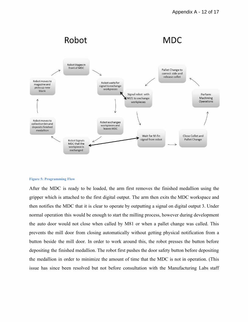
Figure 5: Programming Flow
After the MDC is ready to be loaded, the arm first removes the finished medallion using the
gripper which is attached to the first digital output. The arm then exits the MDC workspace and
then notifies the MDC that it is clear to operate by outputting a signal on digital output 3. Under
normal operation this would be enough to start the milling process, however during development
the auto door would not close when called by M81 or when a pallet change was called. This
prevents the mill door from closing automatically without getting physical notification from a
button beside the mill door. In order to work around this, the robot presses the button before
depositing the finished medallion. The robot first pushes the door safety button before depositing
the medallion in order to minimize the amount of time that the MDC is not in operation. (This
issue has since been resolved but not before consultation with the Manufacturing Labs staff
Appendix A - 12 of 17

members.) After the medallion is deposited, the arm is ready to start again at the beginning of the
loop, and moves back to its starting position near the magazine.
Appendix A - 13 of 17

Results and Discussion The goals of this project were obtained. There is no needed human intervention between
loading medallion blanks into the magazine and removing the bin of finished medallions. The
MDC is only interrupted between machining cycles for a few seconds while the robot swaps
workpieces. The cycle time for the robot to reset is shorter than the predicted cycle time for the
engraving operation. The workholding is automatically operated by the MDC and the workpieces
are not damaged by the process.
One issue that should be addressed is the fact that in the submitted video the robot is
shown physically pressing the “Part Ready” button on the MDC. This was done as a workaround
to the fact that the auto door close command was not working and auto door operation as part of
the pallet change command on the MDC had been disabled. Since neither of these issues could
be properly fixed before the submission deadline for the video, the “Part Ready” button was a
temporary solution to get the program to work. Since then, it has not been determined why the
auto door will not respond to the “M81” command but auto door operation was reenabled as
part of the pallet change call. This has been tested with the program and shown to allow the
program to properly operate.
Appendix A - 14 of 17
Conclusions Though the program works as intended, if the project were to be done again the project
team would perform the project completely differently. To start, the MDC is currently
configured such that the air lines on both sides of the machine’s table activate and deactivate
together. However, the MDC appears to already be plumbed for the two sides to be operated
separately; so all that would be needed to enable independent operation is attaching one airline to
a different solenoid. This is the first thing the project team would do differently.
To enable efficient use of both sides of the MDC’s table, the programming on both the
MDC and the robot would need to be done differently. Currently, the MDC calls the robot using
an M21 command which means that it waits for the robot to tell it that the robot is done before
the MDC moves onto the next line of code. Since the goal is to get the MDC machining and the
robot tending simultaneously this would not work. Instead, what could be done is the MDC calls
the robot using M21 and the robot replies that it has received the message before doing anything
else. This allows the MDC to continue while the robot does its job. Then, when the MDC is
ready to pallet change, to confirm that the robot is ready for the MDC to pallet change the MDC
can call M22 which will feed a new input for the robot. The robot will then finish its job and get
clear if necessary and close the Mfin signal thereby completing the M22 call. Once the M22 call
is completed, the MDC can continue and both the MDC and the robot can start over.
Where this project to be done again, the magazine system would also be implemented
differently. Though functional, as the medallions fall down the magazine the magazine will
occasionally drop a medallion off the robot end. It also offers low repeatability which means that
the position for loading/unloading the collet holder must be tuned when the magazine gets
moved. As an ultimate solution, the team proposes making a magazine out of several feet of
metal bar stock. A groove almost the length of the bar and slightly wider than the medallions
would be cut into the bar to a depth of 3/16” (1/16” less than the height of the medallions.). The
groove would be open through the end of the bar on one side and end in a 1¼” radius on the
other side for control of the position of the next medallion to be loaded. A cross bar that would
also be added so that it was above the second to next medallion to be loaded in such a way as to
Appendix A - 15 of 17

prevent lifting of the second to next medallion. A switch would also be added to see if there is a
medallion ready to be loaded.
Appendix A - 16 of 17

Bibliography 1. HAAS Mill Operator's Manual 9682000 Revision B. (2014, October). Retrieved March
1, 2015. 2. Electrical Service Manual 960284A RevA. (2006, June). Retrieved April 1, 2015. 3. VF Series Series Manual 968100G RevG. (2003, June). Retrieved April 1, 2015.
Appendix A - 17 of 17
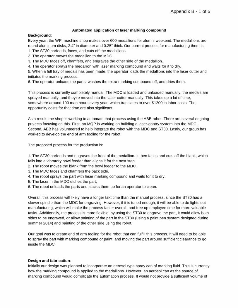
Automated application of laser marking compound
Background:
Every year, the WPI machine shop makes over 600 medallions for alumni weekend. The medallions are
round aluminum disks, 2.4" in diameter and 0.25" thick. Our current process for manufacturing them is:
1. The ST30 barfeeds, faces, and cuts off the medallions.
2. The operator moves the medallion to the MDC.
3. The MDC faces off, chamfers, and engraves the other side of the medallion.
4. The operator sprays the medallion with laser marking compound and waits for it to dry.
5. When a full tray of medals has been made, the operator loads the medallions into the laser cutter and
initiates the marking process.
6. The operator unloads the parts, washes the extra marking compound off, and dries them.
This process is currently completely manual. The MDC is loaded and unloaded manually, the medals are
sprayed manually, and they're moved into the laser cutter manually. This takes up a lot of time,
somewhere around 100 man hours every year, which translates to over $1200 in labor costs. The
opportunity costs for that time are also significant.
As a result, the shop is working to automate that process using the ABB robot. There are several ongoing
projects focusing on this. First, an MQP is working on building a laser-gantry system into the MDC.
Second, ABB has volunteered to help integrate the robot with the MDC and ST30. Lastly, our group has
worked to develop the end of arm tooling for the robot.
The proposed process for the production is:
1. The ST30 barfeeds and engraves the front of the medallion. It then faces and cuts off the blank, which
falls into a vibratory bowl feeder than aligns it for the next step.
2. The robot moves the blank from the bowl feeder to the MDC.
3. The MDC faces and chamfers the back side.
4. The robot sprays the part with laser marking compound and waits for it to dry.
5. The laser in the MDC etches the part.
6. The robot unloads the parts and stacks them up for an operator to clean.
Overall, this process will likely have a longer takt time than the manual process, since the ST30 has a
slower spindle than the MDC for engraving. However, if it is tuned enough, it will be able to do lights out
manufacturing, which will make the process faster overall, and free up employee time for more valuable
tasks. Additionally, the process is more flexible: by using the ST30 to engrave the part, it could allow both
sides to be engraved, or allow painting of the part in the ST30 (using a paint pen system designed during
summer 2014) and painting of the other side using the robot.
Our goal was to create end of arm tooling for the robot that can fulfill this process. It will need to be able
to spray the part with marking compound or paint, and moving the part around sufficient clearance to go
inside the MDC.
Design and fabrication:
Initially our design was planned to incorporate an aerosol type spray can of marking fluid. This is currently
how the marking compound is applied to the medallions. However, an aerosol can as the source of
marking compound would complicate the automation process. It would not provide a sufficient volume of
Appendix B - 1 of 5

marking compound per container to adequately run in a “lights off” manufacturing setting. The necessity
to change out cans in an automated environment would be problematic mainly due to the fact that it
would be difficult to gage how much compound is left in the can until it ultimately ran out. A much more
efficient solution would be a sprayer with a remote tank which could facilitate a much larger volume of
marking compound.
To accommodate the needs for automation, a spray gun with a remote tank system was obtained and
modified. To control the air output of the sprayer, a solenoid was implemented directly in line with the air
feed to the sprayer. This control only needed to actuate on and off, as the adjustment for the amount of
air pressure was separately controlled via the regulator on the remote tank. Also, the spray pattern/area is
also controlled with a separate adjustable knob, so the main air switch could be completely bypassed by
the solenoid.
To control the amount of compound sprayed, a separate pneumatic cylinder was incorporated directly into
the sprayer gun. In order to fit the cylinder, a brass thread adapter needed to be manufactured. This
adapter allowed the cylinder to thread directly into the section of the sprayer gun where the spray volume
knob was previously. In order to maintain the adjustability of the spray volume, a threaded coupler was
manufactured. This coupler had an adjusting nut with corresponding lock nut to control the spray volume.
The original portion of the spray volume needle was kept and a threaded portion was added between to
the cylinder. The nuts on this threaded portion acted as a stopper for the actuation of the needle for the
spray volume. Depending on their positioning, more or less compound would be sprayed. The section of
the coupler connecting directly to the cylinder was connected via a correcting spring. This spring not only
reduced the shock on the needle valve from the cylinder, but also aided in maintaining the alignment of
the system.
To manipulate the medallions, a vacuum pick up tool was chosen, as the medallions have a large flat
surface and the tool would easily be able to grab hold of which. The sprayer gun chosen had a hook for
hanging the sprayer gun in an upright position, which proved a convenient and functional location to
mount the vacuum tool. It was essentially 90 degrees from the spray nozzle and was out of the spray
pattern. It was easily affixed with a hose clamp and provided simple switching between the spraying and
pick up functions by simply rotating the end effector.
To mount the sprayer and vacuum pick up tool to the robot, it was decided that the fixture would be
fabricated as opposed to machined. This not only was more cost effective, but simpler and easier to
implement as well. Machining a complex fixturing bracket would require more time, materials, and design
than the scope of this project would allow.
A piece of steel channel that sprung to fit the width of the sprayer gun was chosen and a slot was milled
in the rear of said channel to accommodate the existing adjustment knobs and added cylinder. The
sprayer then fit snuggly into the steel channel, but in order to maintain its rigidity and guarantee the
sprayer stayed in place, it was also held by two hose clamps. In order to offset the sprayer an adequate
distance from the robot arm to accommodate the added cylinder, two pieces of steel pipe were welded to
the steel channel with feet attached that allowed for the whole fixture to bolt directly to the end of the
robot. The fixture was then painted to reduce the risk of oxidation and maintain its longevity.
Appendix B - 2 of 5
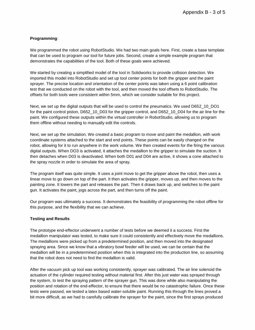
Programming:
We programmed the robot using RobotStudio. We had two main goals here. First, create a base template
that can be used to program our tool for future jobs. Second, create a simple example program that
demonstrates the capabilities of the tool. Both of these goals were achieved.
We started by creating a simplified model of the tool in Solidworks to provide collision detection. We
imported this model into RobotStudio and set up tool center points for both the gripper and the paint
sprayer. The precise location and orientation of the center points was taken using a 6 point calibration
test that we conducted on the robot with the tool, and then moved the tool offsets to RobotStudio. The
offsets for both tools were consistent within 5mm, which we consider suitable for this project.
Next, we set up the digital outputs that will be used to control the pneumatics. We used D652_10_DO1
for the paint control piston, D652_10_D03 for the gripper control, and D652_10_D04 for the air line for the
paint. We configured these outputs within the virtual controller in RobotStudio, allowing us to program
them offline without needing to manually edit the controls.
Next, we set up the simulation. We created a basic program to move and paint the medallion, with work
coordinate systems attached to the start and end points. These points can be easily changed on the
robot, allowing for it to run anywhere in the work volume. We then created events for the firing the various
digital outputs. When DO3 is activated, it attaches the medallion to the gripper to simulate the suction. It
then detaches when D03 is deactivated. When both D01 and D04 are active, it shows a cone attached to
the spray nozzle in order to simulate the area of spray.
The program itself was quite simple. It uses a joint move to get the gripper above the robot, then uses a
linear move to go down on top of the part. It then activates the gripper, moves up, and then moves to the
painting zone. It lowers the part and releases the part. Then it draws back up, and switches to the paint
gun. It activates the paint, jogs across the part, and then turns off the paint.
Our program was ultimately a success. It demonstrates the feasibility of programming the robot offline for
this purpose, and the flexibility that we can achieve.
Testing and Results
The prototype end-effector underwent a number of tests before we deemed it a success. First the
medallion manipulator was tested, to make sure it could consistently and effectively move the medallions.
The medallions were picked up from a predetermined position, and then moved into the designated
spraying area. Since we know that a vibratory bowl feeder will be used, we can be certain that the
medallion will be in a predetermined position when this is integrated into the production line, so assuming
that the robot does not need to find the medallion is valid.
After the vacuum pick up tool was working consistently, sprayer was calibrated. The air line solenoid the
actuation of the cylinder required testing without material first. After this just water was sprayed through
the system, to test the spraying pattern of the sprayer gun. This was done while also manipulating the
position and rotation of the end-effector, to ensure that there would be no catastrophic failure. Once these
tests were passed, we tested a latex based water-soluble paint. Running this through the lines proved a
bit more difficult, as we had to carefully calibrate the sprayer for the paint, since the first sprays produced
Appendix B - 3 of 5

a much too thick layer of paint. We also experienced leaking at the spray volume leaking, that ended
being a result of our own missus of the sprayer, which cannot be used upside down. This required an
adjustment in the intended tool paths, but was easily fixable in the programming. Once this and other
similar problems were worked out, we were able to get a consistent layer of paint out onto the medallion.
With the intend result of the project being the manipulation and then spraying of a medallion, this project
resulted in a success. With some adjustment and refinement, this could be adapted to use the laser
marking compound instead.
The one notable issue we had was this paint spraying created a considerable mess. While we had paper
and cardboard down to spray into so that we wouldn’t be coating everything in the shop in a layer of
bubblegum pink paint, the back spray was enough to speckle the floor and parts of the surrounding area.
With this in mind a simple enclosure would be a good idea to implement, but what that would be depends
greatly upon how this ends up being integrated into the production line. Ideally, the spraying would be
done with the medallion fixtured within Mill Drill Center, in which case the enclosure would need to be
built into the MDC, so that we don’t coat half of this machine. Another option would be a separate
spraying station, where medallions could be coated with compound and allowed to dry before the robot
would move it again. In this second case, we would be building a simple custom enclosure that provides
just enough room for the end effector and medallion to be maneuvered in. It is important to remember
though that the marking compound is much neater than the paint we used, creating much less mess
when sprayed, so back spray might be much less of an issue. If back spray is an issue, continued use
might require a shield for the ABB robot. This could be a simple bagging of the robot, or an added splatter
shield at the tool end. What option is used here, however, will depend upon how it gets integrated into the
production line, and will thus be entirely driven by the workspace in question. Since this workspace was
not a part of project, we did not address this issue, but the results we had will be extremely useful to this
future decision.
Moving forward with the project:
While we successfully proved that the painting process will work, it will still need to be developed more for
the production process.
Robot end of arm tooling:
We will need sensors integrated so it can detect failure and stop the process. This may be a camera that
can detect whether the part has been painted or not.
We will need to create a more accurate collision model for the tool for use in tight spaces.
We will need to configure the paint sprayer to use laser marking compound.
We need to create a more streamlined system for the pneumatics and electronics that won't get in the
way during operation.
Controls:
We need to integrate the robot with the controls of the ST30 and MDC. ABB has volunteered to assist
with this.
MDC:
The MDC needs to be configured for pneumatic workholding and have fixtures designed and built. They
will need to be compatible with the pallet changing and the laser that the MQP group is building. They will
also need to be able to tell whether they have a part properly loaded or not.
Appendix B - 4 of 5

ST30SSY:
We need to attach a vibratory bowl feeder to the parts catcher and configure it to align parts for this
project. The bowl feeder will need sensors to tell the robot when it has a part ready.
Appendix B - 5 of 5
USING SERIAL COM ON
THE MDC How to externally interface with Haas machines using the Serial Port
Created by:
Richard Eberheim
12/17/2014
Appendix C - 1 of 12
Important Hardware Notes
• Option only became available with software version 11.11
starting in June 20011
• All machines shipped after that date include it as a standard feature
• Must use Serial Port 2
• No given reason, experience says this won’t work on port 1
• Need DB9 to DB25 cable to connect to the machine
12/17/2014
Appendix C - 2 of 12
Basic Operational Logic
• External Commands allow for both reading and writing
values to macro and system variables
• Machine itself can look at these variables and use these
values to control flow or alter machine operation.
12/17/2014
Appendix C - 3 of 12
A WORD OF WARNING
• THIS DOES NOT PROVIDE “REAL TIME” CONTROL!
• THERE IS A DELAY OF A FEW SECONDS BETWEEN
CHANGING A VARIABLE AND THE MACHINE
RESPONDING
• DO NOT USE THIS METHOD TO DIRECTLY DRIVE THE
MACHINE
12/17/2014
Appendix C - 4 of 12
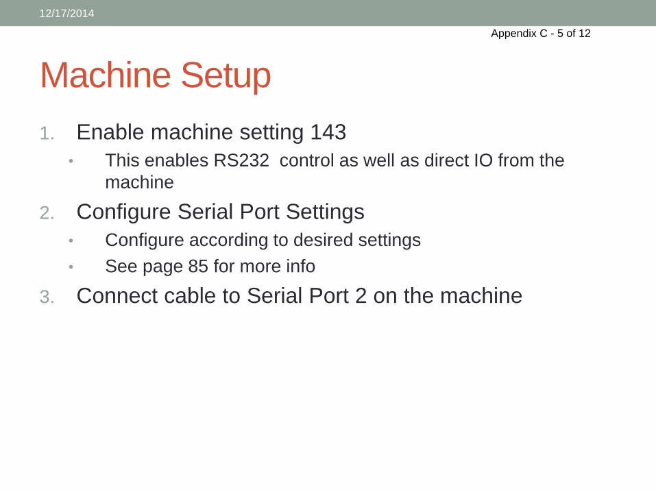
Machine Setup
1. Enable machine setting 143
• This enables RS232 control as well as direct IO from the
machine
2. Configure Serial Port Settings
• Configure according to desired settings
• See page 85 for more info
3. Connect cable to Serial Port 2 on the machine
12/17/2014
Appendix C - 5 of 12
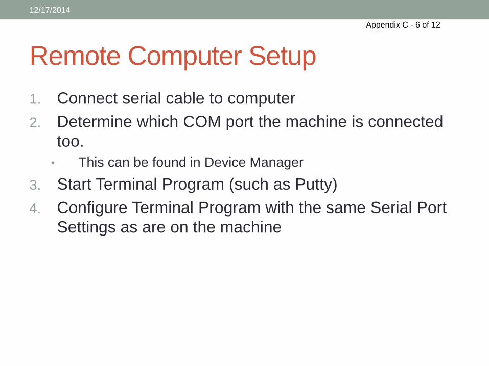
Remote Computer Setup
1. Connect serial cable to computer
2. Determine which COM port the machine is connected
too.
• This can be found in Device Manager
3. Start Terminal Program (such as Putty)
4. Configure Terminal Program with the same Serial Port
Settings as are on the machine
12/17/2014
Appendix C - 6 of 12
Connecting
• After configuring both the machine and the computer, start
the terminal
• You are now ready to control the machine directly using
the commands detailed on the next slides
12/17/2014
Appendix C - 7 of 12
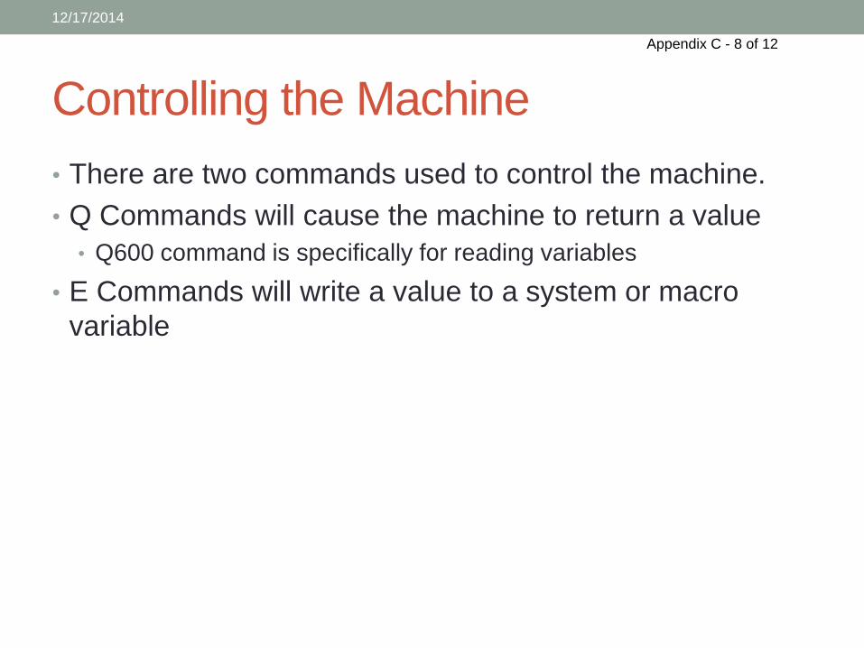
Controlling the Machine
• There are two commands used to control the machine.
• Q Commands will cause the machine to return a value
• Q600 command is specifically for reading variables
• E Commands will write a value to a system or macro
variable
12/17/2014
Appendix C - 8 of 12
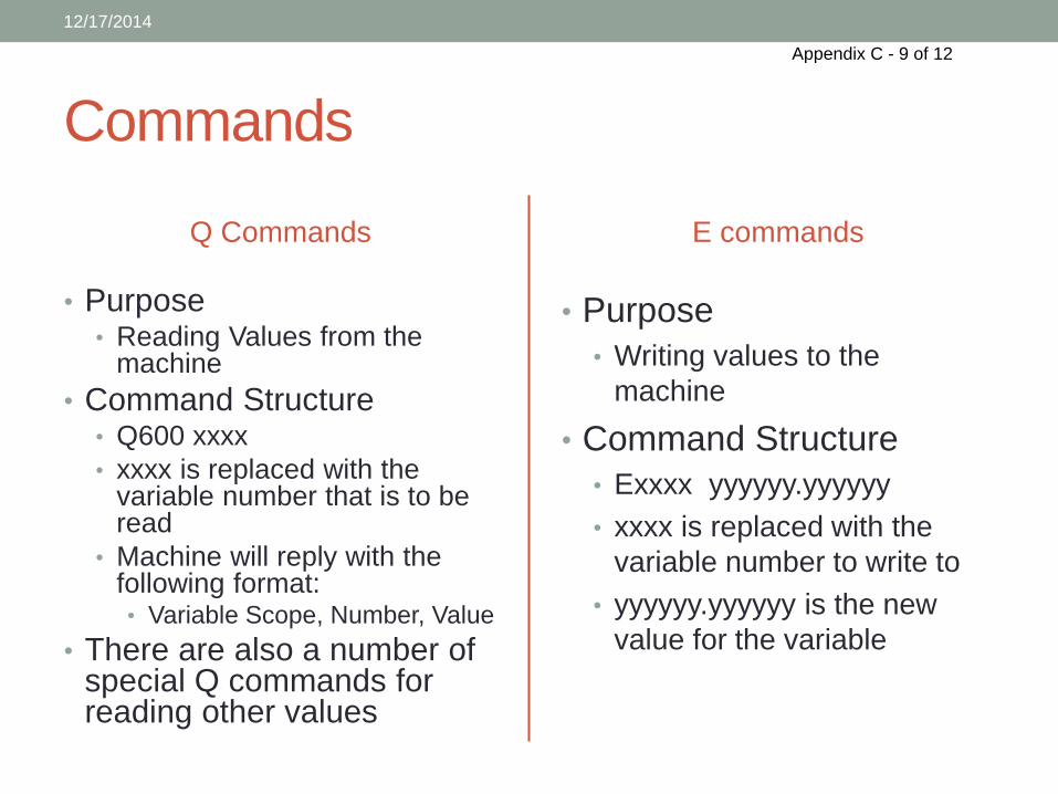
Commands
Q Commands
• Purpose • Reading Values from the
machine
• Command Structure • Q600 xxxx
• xxxx is replaced with the variable number that is to be read
• Machine will reply with the following format: • Variable Scope, Number, Value
• There are also a number of special Q commands for reading other values
E commands
• Purpose
• Writing values to the
machine
• Command Structure
• Exxxx yyyyyy.yyyyyy
• xxxx is replaced with the
variable number to write to
• yyyyyy.yyyyyy is the new
value for the variable
12/17/2014
Appendix C - 9 of 12
Other available commands
• DPRNT[]
• DPRNT[string to send] will send the contained string to the Serial
Port.
• This enables output directly from the machine which can then
trigger an external event
12/17/2014
Appendix C - 10 of 12
Commands Cont.
• See Section 3.5 RS232 in the manual (page 81)
• See page 82 and 83 in the manual for more information
on commands, including other special Q commands
• See page 216 for more information on DPRNT[]
• IMPORTANT: DPRNT[] COMMANDS ARE PROCESS
AND PERFORMED AT INTERPRETATION TIME, NOT AT
EXECUTION TIME.
• This can be eliminated with look ahead prevention with command
G103, but look ahead cannot be used while machine is using cutter
compensation
12/17/2014
Appendix C - 11 of 12
Bibliography
1. http://www.cnczone.com/forums/haas-mills/18389-cnc-
4.html
12/17/2014
Appendix C - 12 of 12
195 Industrial Road Fitchburg, MA 01420 978-342-9800
Proposal For: Edmund Resor, WPI
Appendix D - 1 of 15
195 Industrial Road Fitchburg, MA 01420 978-342-9800
November 20, 2014’ Edmund Resor WPI 100 Institute Road Worcester, MA 01609-2280
Dear Edmund, First and foremost thank you for taking the time to consider Vytek as a laser system supplier. We appreciate the opportunity to provide you with additional information on our systems. I have provided you with an overview of our FC series OEM laser system along with a proposal.
I remain at your disposal to answer any questions you might have. Sincerely, Robin Barbero 978-849-1404 978-342-9800 X404
Appendix D - 2 of 15
195 Industrial Road Fitchburg, MA 01420 978-342-9800
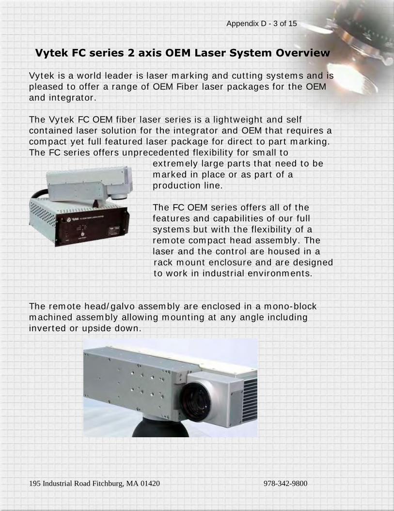
Vytek FC series 2 axis OEM Laser System Overview
Vytek is a world leader is laser marking and cutting systems and is pleased to offer a range of OEM Fiber laser packages for the OEM and integrator. The Vytek FC OEM fiber laser series is a lightweight and self contained laser solution for the integrator and OEM that requires a compact yet full featured laser package for direct to part marking.
The FC series offers unprecedented flexibility for small to extremely large parts that need to be marked in place or as part of a production line. The FC OEM series offers all of the features and capabilities of our full systems but with the flexibility of a remote compact head assembly. The
laser and the control are housed in a rack mount enclosure and are designed to work in industrial environments.
The remote head/galvo assembly are enclosed in a mono-block machined assembly allowing mounting at any angle including inverted or upside down.
Appendix D - 3 of 15
195 Industrial Road Fitchburg, MA 01420 978-342-9800
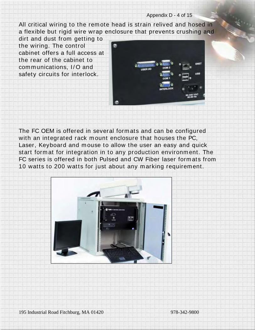
All critical wiring to the remote head is strain relived and hosed in
a flexible but rigid wire wrap enclosure that prevents crushing and dirt and dust from getting to the wiring. The control cabinet offers a full access at the rear of the cabinet to communications, I/O and safety circuits for interlock.
The FC OEM is offered in several formats and can be configured with an integrated rack mount enclosure that houses the PC, Laser, Keyboard and mouse to allow the user an easy and quick start format for integration in to any production environment. The
FC series is offered in both Pulsed and CW Fiber laser formats from 10 watts to 200 watts for just about any marking requirement.
Appendix D - 4 of 15
195 Industrial Road Fitchburg, MA 01420 978-342-9800
The FC OEM series can accommodate:
Flat surfaces Round surfaces Complex angles Inverted surfaces Vertical surfaces Custom fixturing available
The FC series is the ideal laser marking solution when you need to
be ready for a wide range of marking requirements and easy integration into any environment. Features Include: High performance Integrated Fiber laser with power options
from 10 to 200 watts Ultra-Light weight galvo assembly for easy integration. Full featured FiberScan C5 software with serialization
standard Low power consumption operates at 110 or 220 volts using
less then 250 watts Excellent beam quality M2< 1.5 Up to 50% wall plug efficiency 2.5 meter working cable with optional extender to 5 meters
for some models Hi performance scan head made in the USA
Appendix D - 5 of 15
195 Industrial Road Fitchburg, MA 01420 978-342-9800
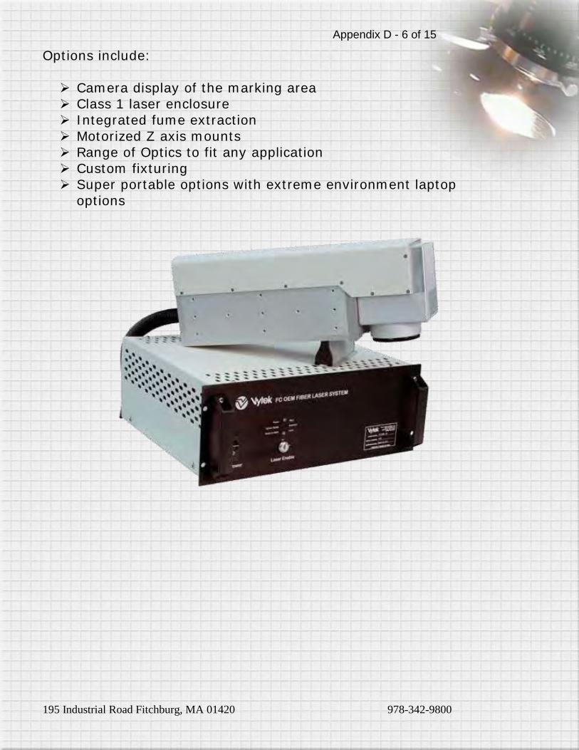
Options include:
Camera display of the marking area Class 1 laser enclosure Integrated fume extraction Motorized Z axis mounts Range of Optics to fit any application Custom fixturing Super portable options with extreme environment laptop
options
Appendix D - 6 of 15
195 Industrial Road Fitchburg, MA 01420 978-342-9800
FiberScan C5 is the latest generation of marking, engraving and
cutting software specifically designed for Galvo/Scanner based systems. FiberScan is an intuitive easy to learn interface. FiberScan C5 is an integrated solution that runs in conjunction with Vytek’s exclusive scanner control system over a TCP/IP network connection. FiberScan C5 Can:
Open multiple jobs
Multi-head capable External control interface over RS-232, TCP/IP and Profibus
(streaming mode) 4-axis motor control for rotary indexers, x-y tables, rotary
tables, etc. Mark any installed TrueType font with serialization, and radial
or vertical text Add Background templates Preview mark capability with visible pointer beam
Allows importing of many graphics file formats Runs on Windows XP, Vista and 7 Supports linear barcode types Code 39, Codabar, Code 93, Code 128, Interleaved, 2 of 5,
POSTNET, UPC A, UPC E, EAN 13, BookLan Supports 2D barcode types, DataMatrix, Denso QR Code,
PDF417 Extensive array of Automation objects, Wait for input, Set
Output, Time Delay, Message Box XY Motion, Serial
Communication, Run Application, Alignment Tool, Laser Control
Language Support English, German, Italian, Japanese, Korean, Spanish, Chinese (Simplified) Chinese (Traditional),
Appendix D - 7 of 15
195 Industrial Road Fitchburg, MA 01420 978-342-9800
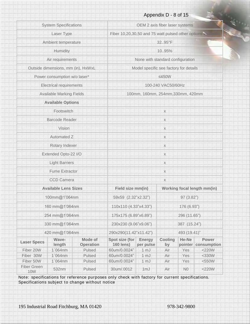
System Specifications OEM 2 axis fiber laser systems
Laser Type Fiber 10,20,30,50 and 75 watt pulsed other options available
Ambient temperature 32..95°F
Humidity 10..95%
Air requirements None with standard configuration
Outside dimensions, mm (in), HxWxL Model specific see factory for details
Power consumption w/o laser* ≤450W
Electrical requirements 100-240 VAC50/60Hz
Available Marking Fields 100mm, 160mm, 254mm,330mm, 420mm
Available Options
Footswitch x
Barcode Reader x
Vision x
Automated Z x
Rotary Indexer x
Extended Opto-22 I/O x
Light Barriers x
Fume Extractor x
CCD Camera x
Available Lens Sizes Field size mm(in) Working focal length mm(in)
100mm@1’064nm 59x59 (2.32”x2.32”) 97 (3.82”)
160 mm@1’064nm 110x110 (4.33”x4.33”) 176 (6.93”)
254 mm@1’064nm 175x175 (6.89”x6.89”) 296 (11.65”)
330 mm@1’064nm 230x230 (9.06”x9.06”) 387 (15.24”)
420 mm@1’064nm 290x290(11.42”x11.42”) 493 (19.41)”
Laser Specs Wave-
length
Mode of
Operation
Spot size (for
160 lens)
Energy
per pulse
Cooling
by
He-Ne
pointer
Power
consumption
Fiber 20W 1`064nm Pulsed 60um/0.0024” 1 mJ Air Yes <220W
Fiber 30W 1`064nm Pulsed 60um/0.0024” 1 mJ Air Yes <330W
Fiber 50W 1`064nm Pulsed 60um/0.0024” 1 mJ Air Yes <550W
Fiber Green
10W 532nm Pulsed 30um/.0012 1mJ Air N0 <220W
Note: specifications for reference purposes only check with factory for current specifications.
Specifications subject to change without notice
Appendix D - 8 of 15
195 Industrial Road Fitchburg, MA 01420 978-342-9800
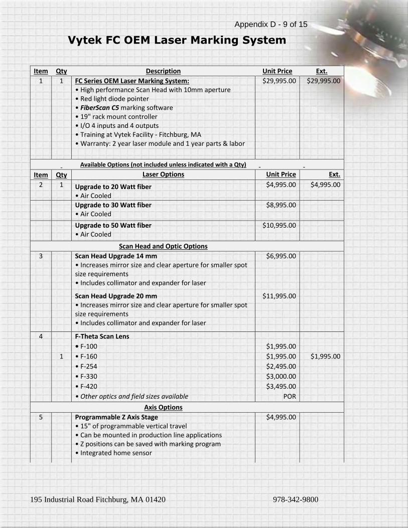
Vytek FC OEM Laser Marking System
Item Qty Description Unit Price Ext.
1 1 FC Series OEM Laser Marking System: • High performance Scan Head with 10mm aperture • Red light diode pointer • FiberScan C5 marking software • 19" rack mount controller • I/O 4 inputs and 4 outputs • Training at Vytek Facility - Fitchburg, MA • Warranty: 2 year laser module and 1 year parts & labor
$29,995.00 $29,995.00
Available Options (not included unless indicated with a Qty)
Item Qty Laser Options Unit Price Ext.
2 1 Upgrade to 20 Watt fiber • Air Cooled
$4,995.00 $4,995.00
Upgrade to 30 Watt fiber • Air Cooled
$8,995.00
Upgrade to 50 Watt fiber • Air Cooled
$10,995.00
Scan Head and Optic Options
3 Scan Head Upgrade 14 mm • Increases mirror size and clear aperture for smaller spot size requirements • Includes collimator and expander for laser
$6,995.00
Scan Head Upgrade 20 mm • Increases mirror size and clear aperture for smaller spot size requirements • Includes collimator and expander for laser
$11,995.00
4 F-Theta Scan Lens
• F-100 $1,995.00
1 • F-160 $1,995.00 $1,995.00
• F-254 $2,495.00
• F-330 $3,000.00
• F-420 $3,495.00
• Other optics and field sizes available POR
Axis Options
5 Programmable Z Axis Stage • 15" of programmable vertical travel • Can be mounted in production line applications • Z positions can be saved with marking program • Integrated home sensor
$4,995.00
Appendix D - 9 of 15
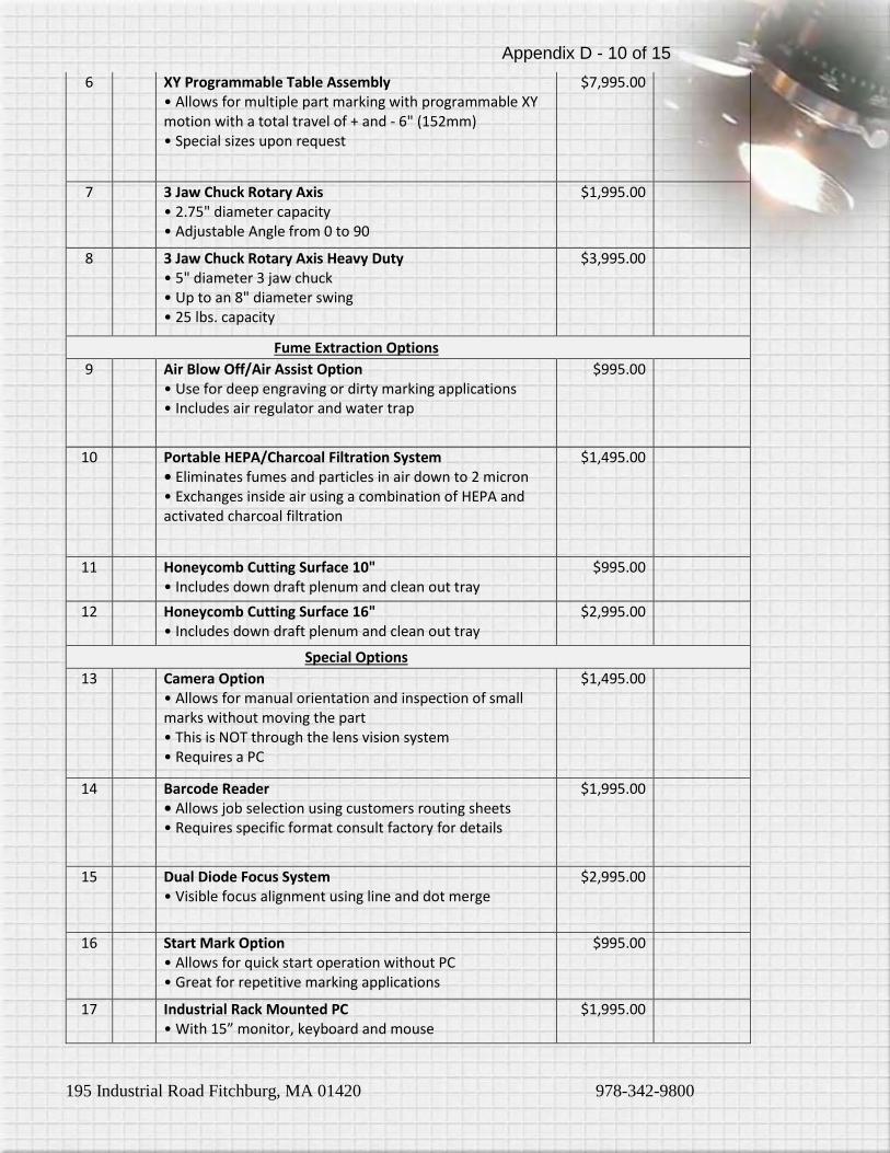
195 Industrial Road Fitchburg, MA 01420 978-342-9800
6 XY Programmable Table Assembly • Allows for multiple part marking with programmable XY motion with a total travel of + and - 6" (152mm) • Special sizes upon request
$7,995.00
7 3 Jaw Chuck Rotary Axis • 2.75" diameter capacity • Adjustable Angle from 0 to 90
$1,995.00
8 3 Jaw Chuck Rotary Axis Heavy Duty • 5" diameter 3 jaw chuck • Up to an 8" diameter swing • 25 lbs. capacity
$3,995.00
Fume Extraction Options
9 Air Blow Off/Air Assist Option • Use for deep engraving or dirty marking applications • Includes air regulator and water trap
$995.00
10 Portable HEPA/Charcoal Filtration System • Eliminates fumes and particles in air down to 2 micron • Exchanges inside air using a combination of HEPA and activated charcoal filtration
$1,495.00
11 Honeycomb Cutting Surface 10" • Includes down draft plenum and clean out tray
$995.00
12 Honeycomb Cutting Surface 16" • Includes down draft plenum and clean out tray
$2,995.00
Special Options
13 Camera Option • Allows for manual orientation and inspection of small marks without moving the part • This is NOT through the lens vision system • Requires a PC
$1,495.00
14 Barcode Reader • Allows job selection using customers routing sheets • Requires specific format consult factory for details
$1,995.00
15 Dual Diode Focus System • Visible focus alignment using line and dot merge
$2,995.00
16 Start Mark Option • Allows for quick start operation without PC • Great for repetitive marking applications
$995.00
17 Industrial Rack Mounted PC • With 15” monitor, keyboard and mouse
$1,995.00
Appendix D - 10 of 15
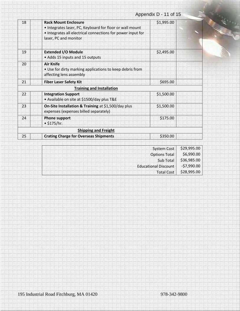
195 Industrial Road Fitchburg, MA 01420 978-342-9800
18 Rack Mount Enclosure • Integrates laser, PC, Keyboard for floor or wall mount • Integrates all electrical connections for power input for laser, PC and monitor
$1,995.00
19 Extended I/O Module • Adds 15 inputs and 15 outputs
$2,495.00
20 Air Knife • Use for dirty marking applications to keep debris from affecting lens assembly
21 Fiber Laser Safety Kit $695.00
Training and Installation
22 Integration Support • Available on site at $1500/day plus T&E
$1,500.00
23 On-Site Installation & Training at $1,500/day plus expenses (expenses billed separately)
$1,500.00
24 Phone support • $175/hr.
$175.00
Shipping and Freight
25 Crating Charge for Overseas Shipments $350.00
System Cost $29,995.00
Options Total $6,990.00
Sub Total $36,985.00
Educational Discount -$7,990.00
Total Cost $28,995.00
Appendix D - 11 of 15

195 Industrial Road Fitchburg, MA 01420 978-342-9800
TERMS & CONDITIONS The placing of this order by Buyer constitutes acceptance by the Buyer of the terms and conditions herein contained. 1. PURCHASE OF EQUIPMENT. Seller shall sell to Buyer, and Buyer shall purchase from Supplier for the Price provided above, the Equipment described above in accordance with the terms and conditions set forth in this Agreement. For purposes of this Agreement, the term "Equipment" shall include all components of the Equipment, all associated software licensed by Seller pursuant to Section 2 hereof, and all upgrades, enhancements, and replacements thereof made available, or required to be made available, to Buyer pursuant to this Agreement. 2. LICENSE OF RELATED SOFTWARE.
A. Seller hereby grants to Buyer a perpetual, irrevocable, nonexclusive, fully paid-up, transferable license to possess and use the operational computer software for the Equipment, including, without limitation, the object code embodiment thereof and all related documentation (collectively, the Software), solely with the Equipment and to reproduce the Software in connection with such use.
B. Buyer acknowledges that it is acquiring no ownership interest in the Software and that all right, title, and interest in and to the Software remain with Seller.
3. INSTALLATION AND TRAINING: Prior to the delivery date set forth above, if Buyer and Seller have agreed, Buyer shall prepare the installation site for the Equipment in accordance with Supplier's installation specifications. Upon notice by Buyer of the arrival of the Equipment at Buyer’s facility, Seller shall install the Equipment in a timely manner and in accordance with Seller’s installation specifications. In addition, Seller will provide Buyer with reasonable product and user training as per the quotation accepted by Buyer. Buyer agrees that no one will use the Equipment who has not been trained and who does not use the required safety equipment and safety practices outlined during the training. 4. WARRANTY: The Equipment is warranted to Buyer to be free from defects in material and workmanship for a period of twelve months for all parts and labor. Seller will repair or replace at its option and no cost to Buyer, any Equipment delivered to Seller's designated facility in a non-operating condition pursuant to the above warranties. Buyer shall be responsible for determining that the Equipment is in a non-operating condition upon receipt and will identify the suspected malfunction to Seller. The Seller’s warranty does not apply to performance of the Equipment caused by abrasive materials, corrosion due to aggressive fluids, lightning, improper voltage supply, mishandling or misapplication in a manner inconsistent with that identified in Seller's catalogs and literature. Any warranty granted by Seller to the Buyer shall be deemed void if the Equipment is used for any purpose not permitted hereunder. In the event that the Equipment is altered or repaired by the Buyer without prior written approval by the Seller, all warranties are void. In no event shall Seller be liable for collateral or consequential damages. In addition, the Buyer shall indemnify Seller and hold Seller harmless from and against any and all claims, damages, losses, costs, expenses, and other liability of whatever nature that Seller suffers or incurs by reason of any such unintended use. This warranty is made in lieu of any warranty expressed, implied, or statutory; and no agreement extending or modifying it will be binding upon Seller unless in writing and signed by a duly authorized officer. EXCEPT FOR THE EXPRESS WARRANTIES STATED ABOVE, VYTEK, INC. DISCLAIMS ALL WARRANTIES ON PRODUCTS INCLUDING ALL IMPLIED WARRANTIES OF MERCHANTABILITY AND FITNESS AND THE STATED WARRANTIES ARE IN LIEU OF ALL OBLIGATIONS OR LIABILITIES ON THE PART OF VYTEK, INC. FOR DAMAGES, INCLUDING BUT NOT LIMITED TO SPECIAL, INDIRECT OR CONSEQUENTIAL DAMAGES, INCLUDING BUT NOT LIMITED TO SPECIAL, INDIRECT OR CONSEQUENTIAL DAMAGES ARISING OUT OF OR IN CONNECTION WITH THE USE OR PERFORMANCE OF THE PRODUCTS. 5. INDEMNITY: Buyer shall indemnify and save the Seller harmless from any and all claims by, for, or against the Seller or Buyer as a result of injury or damage to Buyer, Buyer's employees, or other persons caused by the equipment during the course of its use herein sold by the Seller to the Buyer, unless the injury or damages is as result of negligent manufacture or otherwise. 6. GENERAL PROVISIONS: This contract is made, governed by, and shall be construed in accordance with the laws of the Commonwealth of Massachusetts. Seller and Buyer hereby consent to the exclusive jurisdiction and venue of the courts of Massachusetts or of federal courts in Massachusetts with respect to any dispute, controversy or other matter relating to or arising out of this order and agree that any such any dispute, controversy or other matter relating to or arising out of this order may only be brought in the courts of Massachusetts or of federal courts in Massachusetts. This contract is non-assignable, and any attempt to assign any right, duties or obligations under this contract will be void, except in the case of a change in ownership, contract will insure to present owner. All rights and remedies of either party, whether evidenced hereby or by any other contract, instrument or paper, shall be cumulative and may be evidenced hereby or by any other contract, instrument or paper, shall be cumulative and may be exercised singularly or concurrently. In the event either party shall, on any occasion, fail to perform any term of this contract, and the other party shall not enforce that term, failure to enforce on that occasion shall not prevent enforcement on any other occasion. 7. NOTICES: All notices, requests, consents, and other communications required, or permitted hereunder shall be in writing and shall be mailed by registered or certified mail, postage prepaid, or transmitted by Telex, TXW, or Facsimile to addresses set forth below, addresses subject to change by written notice. 8. ENTIRE AGREEMENT: This Agreement constitutes the entire Agreement of parties with reference to the subject matter hereof. 9. SHIPMENT AND PASSAGE OF TITLE: Shipment will be made F.O.B. Point of Origin. In the absence of specific shipping instructions, method of shipment will be determined by the Seller. In all cases, Seller's responsibility (except as stated in its
Appendix D - 12 of 15

195 Industrial Road Fitchburg, MA 01420 978-342-9800
warranty) cease and risk of loss shall pass upon delivery of the material to the carrier, irrespective of the method of shipment and method of payment for shipment. 10. SECURITY INTEREST: Buyer hereby grants to seller a first priority lien and purchase money security interest in the Equipment purchased hereunder and in all subsequently purchased Equipment, and any and all components, material, systems and sub-systems incorporated therein, together with all operating and maintenance manuals and other documents required by this Agreement, and all moneys, securities and other property resulting from the sale, pledge or other disposition of the same. Buyer will keep the Equipment free from any and all adverse liens, security interests and encumbrances. Buyer hereby agrees to execute any and all promissory notes, UCC-1 Financing Statements and other documents, and pay any and all fees, taxes or other costs as necessary to allow the Seller to perfect its interest in the Equipment Seller agrees that upon full satisfaction of the purchase price and all related charges for the Equipment, Seller shall execute UCC termination statements as necessary. 11. DELIVERY: Seller will endeavor to meet delivery schedules, but in no case shall Seller incur any liability, consequential or otherwise, for any delays or failure to deliver as the result of any cause beyond its reasonable control, including, without limiting the generality of the foregoing, acts of God, of a public enemy, or of the Buyer; or disputes, accidents, transportation conditions, government actions of any kind, inability to secure adequate material or labor, or any cause similar or dissimilar to the foregoing. Quoted delivery dates are Seller's best estimate, on the basis of current schedules. In no event shall Seller be liable for special or consequential damages resulting from failure to meet requested delivery schedules. Incremental or additional costs incurred by Seller as a result of Buyer's alternation of the delivery schedule, whether or not such alteration constitutes a change under Paragraph 11 hereof, will be borne by Buyer. Buyer agrees to inspect the equipment at Seller's designated facility prior to shipment, at Buyer's expense, for the purpose of confirming the operating condition, functions, features, and performance of the equipment. If buyer fails to inspect the equipment prior to shipment to Buyer's designated facility, Buyer relinquishes the right to refuse acceptance of and to make payment for the equipment for reasons relating to the equipment's functions, features and/or performance.
12. TERMINATION AND BREACH: This contract may be terminated by Buyer only when approved in writing by Seller. In the event of termination, Seller will take immediate steps to mitigate termination costs to Buyer, but Buyer shall reimburse Seller for the cost of labor, overhead, and material costs and other commitments made by seller in reliance upon this order. Insolvency of the Buyer, the filing of a petition in bankruptcy or the commencement of any insolvency or receivership proceeding shall be deemed a termination of the Buyer. Notwithstanding any provision to the contrary herein, if Seller shall at any time have grounds for insecurity with respect to Buyer's performance hereunder and buyer shall fail to provide adequate assurance of due performance within thirty (30) days after the mailing to it by Seller of a demand for such assurance, then Seller may consider this contract repudiated and shall have all the rights to a Seller for such repudiation under Chapter 106 of the General laws of Massachusetts. 13. CHANGES: No change shall be made in descriptions and specifications relating to this order without the written consent of Seller. Subject to the foregoing, Buyer, by written order, may make changes in drawings, specifications, delivery schedules, shipment or packing of articles if such changes increase or decrease the cost of, or the time required for performance of this order, or otherwise affects any of the provisions of this order, an equitable adjustment shall be made in the price or delivery schedule, or both, and in such other provisions of this order as may be so affected, and the order shall be modified in writing accordingly. Any claim for adjustment hereunder may be asserted at any time prior to shipment of the last item due under this order. It is agreed that the prices stated herein are based upon normal supplied and labor costs and that any request of Buyer necessitating overtime or other expense shall be deemed a change under this provision. 14. REPRODUCTION RIGHTS: Designs, processes, drawings, specifications, reports, photographs, data and other technical or proprietary information relating to this order shall remain the property of Seller and Buyer agrees that it will not use any of such items or information therein for the production or procurement from any other source of articles furnished in connection with this order, nor reproduce or otherwise appropriate the same without the prior written authorization of Seller or until such items or information become publicly known through a source other than Buyer. 15. CONFIDENTIAL: Buyer agrees that it will not disclose or make available to any third party any of the items referred to in Paragraph 14, or any information contained in such items without obtaining the prior written consent of Seller or until such information becomes publicly known, through a source other than Buyer. 16. INFRINGEMENT: Except insofar as this order calls for articles or materials not manufactured by Seller, or manufactured by Seller pursuant to Buyer's drawings or specifications, Seller agrees to defend any suit or proceedings against Buyer based upon an infringement claim that any article or part thereof manufactured hereunder, by reason of its manufacture, sale or use, infringes any United States patent which was issued at date of contract, and agrees to pay the amount of any judgment against Buyer resulting therefrom, together with all costs and expenses incident thereof, provided however, that such claim does not relate to articles or materials manufactured pursuant to Buyer's drawings or specifications, provided, further, that Seller is notified of such an infringement claim or the threat of commencement of such suit or proceeding within two weeks of the time Buyer received notice thereof and is given an opportunity, with the cooperation of Buyer, to conduct the defense or settlement thereof. Seller's liability to pay or incur expenses or to pay any costs, damages or judgments under the foregoing provision shall be limited to an amount equal
Appendix D - 13 of 15

195 Industrial Road Fitchburg, MA 01420 978-342-9800
to Purchase price paid for the articles or material upon which such infringement claim is based less a reasonable allowance for the use and depreciation. Seller reserves the right to substitute for articles, materials, or parts thereof, which in its opinion might infringe other equally suitable products without altering the other conditions before or after sale. Seller shall also have the right to take back infringing articles, materials, or parts thereof, refuting the purchase price or an equitable portion thereof less a reasonable allowance of use and depreciation. Seller assumes no responsibility for the actual or alleged infringement of any foreign patent or other matter except as expressly stated in this Paragraph 17. Buyer agrees to pay to Seller all costs and expenses incurred by Seller in its defense, and to pay the amount of any judgment against Seller, in any suit or proceeding against Seller based upon a claim of infringement, resulting from Buyer's combining any articles supplied hereunder with any articles or device not manufactured or supplied by Seller or from the sale or use of any such combination by Buyer. 17. TAXES: The amount of any present future sales, use, or similar taxes, and import or export tariffs applicable to the products sold hereunder, shall be payable by Buyer when and as incurred. 18. SELLER'S ADDITIONAL REMEDIES: In addition to the rights specified herein, Seller shall have all the rights and remedies of a Seller under Chapter 106 of the General Laws of Massachusetts and no waiver of or failure to enforce and as such right or remedy on one occasion shall be deemed a waiver of such right or remedy on any future occasion. 19. SEVERABILITY: These terms and conditions shall be severable and the invalidity or unenforceability of any of them under any circumstances shall not affect those terms and conditions which are not held to be invalid or unenforceable. 20. BUYER ACKNOWLEDGES THAT SELLER HAS THOROUGHLY EXPLAINED TO BUYER HOW TO SAFELY OPERATE THE EQUIPMENT AND EXPLAINED ALL POTENTIAL HAZARDS THAT COULD RESULT FROM THE IMPROPER USE OF THE EQUIPMENT.
NOTICE: The equipment sold hereby should only be used by properly trained personnel who follow proper safety precautions. Familiarize all persons with safety practices before they use the equipment.
Appendix D - 14 of 15

195 Industrial Road Fitchburg, MA 01420 978-342-9800
Proposal valid through 12/21/2014 Payment Terms: 50% deposit with order Balance prior to shipment Shipping: FOB Fitchburg, MA – Freight collect
Delivery Date: TBD Method of Payment: Wire, Bank Check, or Letter of Credit at site. With this signature, I acknowledge that I have read, understand and agree to the included Terms and Conditions of the following purchase of the laser system described on the preceding pages of this document.
Signature/Title Date
Appendix D - 15 of 15