landslide stabilization in cut zone number 6 from km …
TRANSCRIPT

8th INTERNATIONAL CONFERENCE
Contemporary achievements in civil engineering 22-23. April 2021. Subotica, SERBIA
| CONFERENCE PROCEEDINGS INTERNATIONAL CONFERENCE (2021) | 417
LANDSLIDE STABILIZATION IN CUT ZONE NUMBER 6 FROM KM 28 + 478,00 TO KM 28 + 643,00
Janko Radovanović 1 Marija Lazović Radovanović2 Jelena Nikolić 3 UDK: 624.131.537(497.11)
DOI: 10.14415/konferencijaGFS2021.40 Summary: In the cut zone number 6 on E-80 Niš-Dimitrovgrad highway from km 28 + 478,00 to km 28 + 643,00 slope stability was affected causing mass movement. Additional inclinometers measured the mass wasting thickness between 14 m and 25 m. The height of the cut determined the slope protective backfilled gallery to be the best solution. The paper presents the detailed geostatic calculation of landslide stabilization using computer programs Plaxis 2D and RocScience Slide. Further, it shows the static calculation of the protective gallery in the computer program Radimpex Tower 3D. Results confirmed that the proposed structure was rigid enough to provide the necessary protection for the road structure. Keywords: landslide stabilization, static calculation, backfilled gallery 1. INTRODUCTION On the highway E-80, Niš - Dimitrovgrad, section Prosek - Crvena Reka, in the cut zone no. 6 from km 28 + 478.00 to km 28 + 643.00, the landslide movement occurred. Besides, a high groundwater level affected the parameters of slope shear capacity and stability. Additional inclinometers measured the mass wasting thickness between 14 m and 25 m. The described condition requested temporary material refill at the foot of the slope. The height of the cut determined further study of the slope rehabilitation. After analysis of all possible solutions, it was decided to construct the protective backfilled gallery strong enough to support the embankment above the roof slab. This overlay should serve as a permanent embankment that stabilizes the hill. Eventually, the proposed solution referred to the part of the slope from km 28 + 478.54 to km 28 + 652.02, total L = 174m in length.
1 Janko Radovanović, MSc, Faculty of Civil Engineering, University of Belgrade, Technical director “Beoexpert design” LTD, Ruzvaltova 23, Belgrade, Republic of Serbia, e – mail: [email protected] 2 Dr Marija Lazović Radovanović, Assistant professor , MSc, Faculty of Civil Engineering, University of Belgrade, Belgrade, Republic of Serbia, e – mail: [email protected] 3Jelena Nikolić, Teaching assistant , MSc, Faculty of Civil Engineering, University of Belgrade, Belgrade, Republic of Serbia, e – mail: [email protected]

8. МЕЂУНАРОДНА КОНФЕРЕНЦИЈА Савремена достигнућа у грађевинарству 22-23. април 2021. Суботица, СРБИЈА
418 | ЗБОРНИК РАДОВА МЕЂУНАРОДНЕ КОНФЕРЕНЦИЈЕ (2021) |
Figure 1. Cut zone no.6 from km 28+478,00 to km 28+643,00 2. THE TECHNICAL SOLUTION REPORT The protective gallery foundation comprises Ø1500mm drilled piles 16.0m long at distances of 2.5 m and 3.0 m. The size of the capping beam was b / d = 2.30 m / 1.90 m. The concrete casting went in sections as part of it had to be concreted together with the roof slab to provide beam-slab interaction and form a clamp. The roof was a d = 1.30 m tick monolithic concrete slab with a span from 13.1 m to 15.7 m in the portal zone of the tunnel. Over the concrete slab, a layer of hydro insulation and its protective layer was installed. All reinforced-concrete works were performed using MB30 concrete and B500B reinforcement. As parts of the gallery remained visible at the side, some piles needed additional facing as permanent pillars. Interior walls of the gallery had shotcrete in several layers of about d = 5.0 cm thickness. Both the left and the right side of the gallery had a 30cm thick parapet wall about 1.0 m and 1.70 m high. The embankment in the center of the gallery roof was almost 6.0 m high. The total height of the roof backfill varied from the gallery to the hill.
8th INTERNATIONAL CONFERENCE
Contemporary achievements in civil engineering 22-23. April 2021. Subotica, SERBIA
| CONFERENCE PROCEEDINGS INTERNATIONAL CONFERENCE (2021) | 419
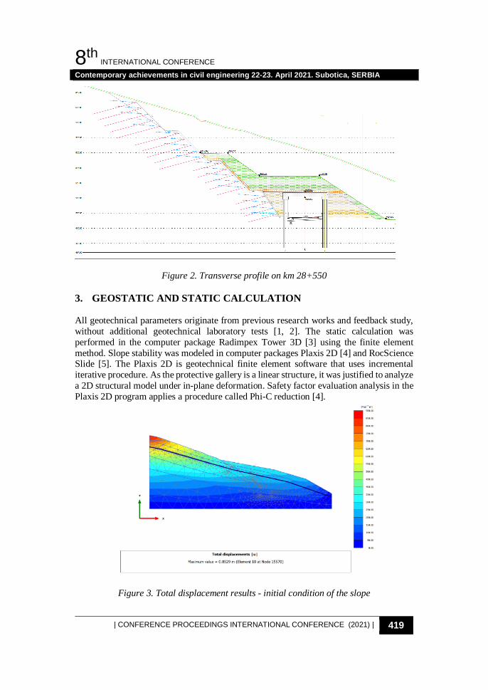
Figure 2. Transverse profile on km 28+550 3. GEOSTATIC AND STATIC CALCULATION
All geotechnical parameters originate from previous research works and feedback study, without additional geotechnical laboratory tests [1, 2]. The static calculation was performed in the computer package Radimpex Tower 3D [3] using the finite element method. Slope stability was modeled in computer packages Plaxis 2D [4] and RocScience Slide [5]. The Plaxis 2D is geotechnical finite element software that uses incremental iterative procedure. As the protective gallery is a linear structure, it was justified to analyze a 2D structural model under in-plane deformation. Safety factor evaluation analysis in the Plaxis 2D program applies a procedure called Phi-C reduction [4].
Figure 3. Total displacement results - initial condition of the slope

8. МЕЂУНАРОДНА КОНФЕРЕНЦИЈА Савремена достигнућа у грађевинарству 22-23. април 2021. Суботица, СРБИЈА
420 | ЗБОРНИК РАДОВА МЕЂУНАРОДНЕ КОНФЕРЕНЦИЈЕ (2021) |
Figure 4. Total displacement results - after the landslide activation and before gallery construction
Figure 5. Total displacement results- after landslide stabilization and gallery construction
The RocScience Slide is a limit equilibrium slope stability program that uses several well-known methods such as Janbu, Bishop, Spencer [6], etc. Sliding mass is divided into lamellae and the safety factor or probability of slope failure presents the ratio of the moments caused by negative and positive forces. The reliable transverse profile for both static and geostatic analysis was at stationing 28 + 600. In the first part of the calculation, a feedback analysis was performed in Slide for the required safety factor to be higher than

8th INTERNATIONAL CONFERENCE
Contemporary achievements in civil engineering 22-23. April 2021. Subotica, SERBIA
| CONFERENCE PROCEEDINGS INTERNATIONAL CONFERENCE (2021) | 421
Fs = 1.20. Obtained restitution force of about 3500k N / m was in the next phase applied to the structure in the Tower as a lateral soil pressure. In addition to lateral soil pressures, calculation included weight, additional dead load, and vertical soil pressures. The envelope of maximum influences determined the dimensions of the structural elements with reinforcement. Finally, Plaxis 2D fulfilled control calculation of slope stability together with the deformation of the structure.
Figure 6. Slope stability calculation - current situation
Figure 7. Slope stability calculation - current situation

8. МЕЂУНАРОДНА КОНФЕРЕНЦИЈА Савремена достигнућа у грађевинарству 22-23. април 2021. Суботица, СРБИЈА
422 | ЗБОРНИК РАДОВА МЕЂУНАРОДНЕ КОНФЕРЕНЦИЈЕ (2021) |
Table 1. Slope stability safety factor in RockScience Slide, cross section at km 28 + 600
Table 2. Slope stability safety factor in Plaxis 2D, cross section at km 28 + 600
Finally, Rocscience Slide analyzed the effects of natural seismic and so the global slope stability. According to the MCS scale, the terrain could reach an earthquake intensity of 7-7.50. Recommended seismicity coefficient equals Kx = 0.025. Under the assumption that the earthquake loading combines only with typical underground water levels during the exploitation, the global safety factor equaled Fs = 1,253. 4. CONSTRUCTION METHODOLOGY
Since the considered works are highly specialized, the paper briefly presents the construction process. Before the execution of the main works, preparatory leveling works, construction of access roads, and work platforms took place. The backfilling finished at the level of the working platform. Someplace, the realignment of a temporary embankment was necessary. Drilling of 16m long Ø1500mm piles followed. To prevent boreholes from crushing it was mandatory to install the reinforcement cage and finish concreting right after drilling. The concreting of the head beams on top of the pile walls happened in sections. The first section took only 1 m of the beam height so that the reinforcement for the clamped connection with the slab could be concreted afterward together with the roof slab. Next, casting 20 cm thick lean concrete slab was to provide the lower formwork for the roof slab. As the gallery roof slab was about 165 m long and 1.30 m thick, the concreting also went in phases. After the concrete had reached the designed strength, the gallery excavation in full height started simultaneously with a shot-creating on both sides in several layers. It prevented the earth material from falling out between the piles. In parallel went the installation of the roof slab waterproofing and its protective layer. Inside the gallery, construction of 30 cm thick and 2.0 m high wall on the left axis and 1.3 m high on the right axis of the gallery finished. Outside the tunnel, it was necessary to clean the pile walls from the temporary embankment and install anchors for reinforcement mesh Q84. In the end, the facing of the protective gallery outside walls included shot-creating in two 5 cm layers along the pile wall. The permanent embankment over the gallery roof
Phase FsInitial condition (feedback study) 0,972Initial condition + embankment at the bottom 1,046Initial condition + embankment at the bottom + high underground water 0,980Initial condition + gallery + embankment over the gallery 1,347
Phase FsInitial condition 1,006Initial condition + gallery + embankment over the gallery 1,329

8th INTERNATIONAL CONFERENCE
Contemporary achievements in civil engineering 22-23. April 2021. Subotica, SERBIA
| CONFERENCE PROCEEDINGS INTERNATIONAL CONFERENCE (2021) | 423
consisted of unified-size crushed stone and the installation of pipe drains. The open part of the gallery had a 30 cm thick and 0.9 m high concrete parapet wall. 5. CONCLUSION
The paper presents the geostatic and static calculation of the protective gallery for landslide stabilization. The comprehensive analysis summarizes the results in RocScience Slide, Plaxis 2D, and Tower 3D. The protective gallery was rigid enough to provide slope stability and adequate protection for the road structure. Upon official approval of the design in 2019, all construction works were successfully performed. To confirm the measures envisaged during exploitation, the measuring system installation is necessary. REFERENCES [1] Hidroprojekat – saobraćaj d.o.o.: Glavni projekat zaštite kosine C6 od km 28+463
do km 28+600, Beograd, 2017. [2] Hidroprojekat – saobraćaj d.o.o.: Geotehnički elaborat zaštitene galerije kosine 6,
Beograd, 2016. [3] Radimpex Software: User Manual for TOWER 7, Beograd, 2018. [4] PLAXIS 2D Tutorial manual, Delft University of Tehnology &Plaxis bv, The
Netherlands, 2018. [5] Slide 2D limit equilibrium slope stability for soil and rock slopes User’s Guide,
USA, 2002. [6] Duncan, M.J.,Wright, S.W.: Soil Strength and Slope Stability, John Wiley& Sons,
2005.
СТАБИЛИЗАЦИЈА КЛИЗИШТА У ЗОНИ УСЕКА БРОЈ 6 ОД КМ 28+478,00 ДО КМ 28+643,00
Резиме: У зони усека број 6 на аутопуту Е-80 Ниш-Димитровград од км 28 + 478,00 до км 28 + 643,00 дошло је до нарушавања стабилности косине и мобилизације масе. Додатним инклинометрима иземерена је дељина мобилисане клизне масе између 14м и 25м. Висина усека определила је да би заштитна конструкција у виду насуте галерије била најбоље решење. У раду је приказан детаљан геостатички прорачун стабилизације клизишта применом рачунарских програма Plaxis 2D и RocScience Slide. Даље у раду извршен је статички прорачун заштитне галерије у рачунарском програму Radimpex Tower 3D. Дoбијени резултати потврдили су да је предложена конструкција била довољно крута да обезбеди неопходну заштиту за коловозну конструкцију. Кључне речи: стабилизација клизишта, статички прорачун, насута галерија