landfill liner and cover systems: design guidelines a ... · landfill liner and cover systems: ......
TRANSCRIPT
Copyright Morton A. Barlaz, NC State University 1
Landfill Liner and Cover Systems:Design Guidelines
• A liner suggests a single layer, a liner system suggests a series of layers working together
• Leakage from liner systems can be very low with proper engineering and construction
• Design principles versus regulations
2
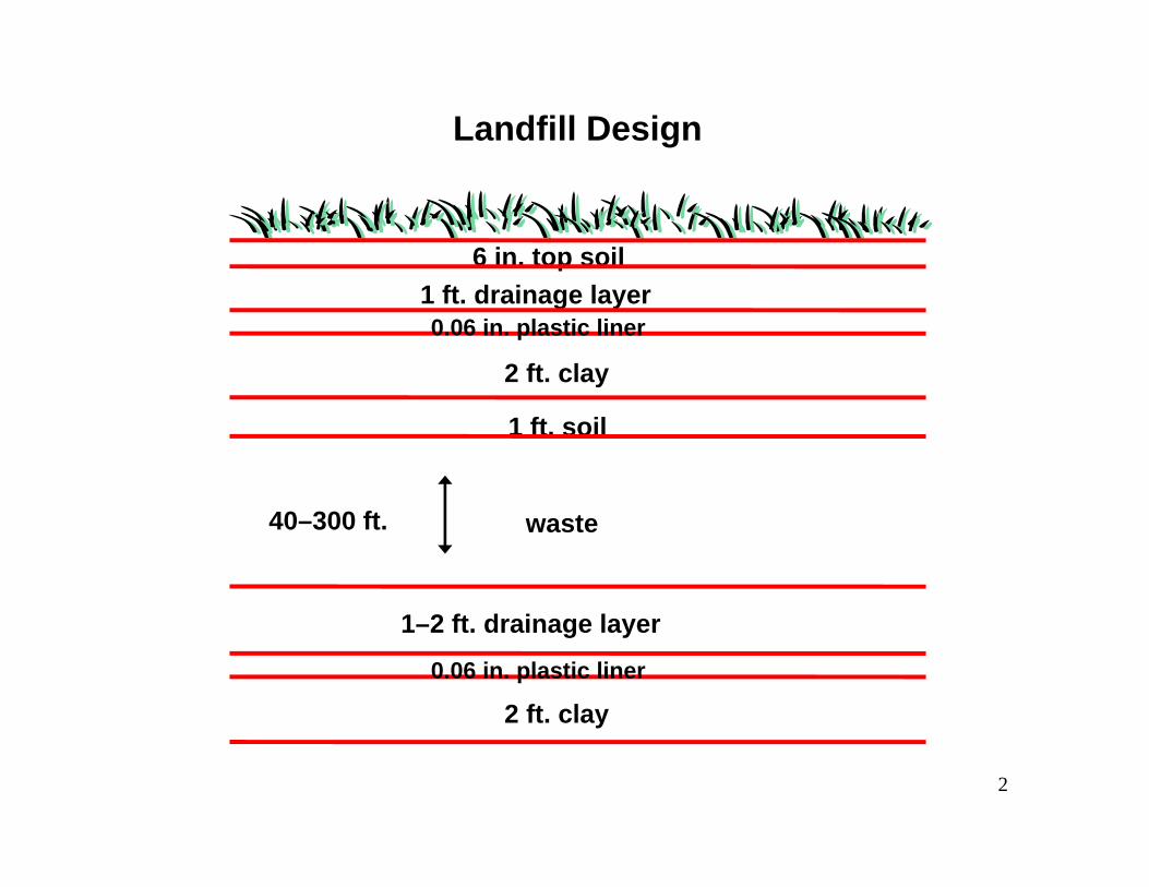
Landfill Design
2 ft. clay
1 ft. soil
2 ft. clay
1–2 ft. drainage layer
6 in. top soil
40–300 ft. waste
1 ft. drainage layer
0.06 in. plastic liner
0.06 in. plastic liner
Copyright Morton A. Barlaz, NC State University 3
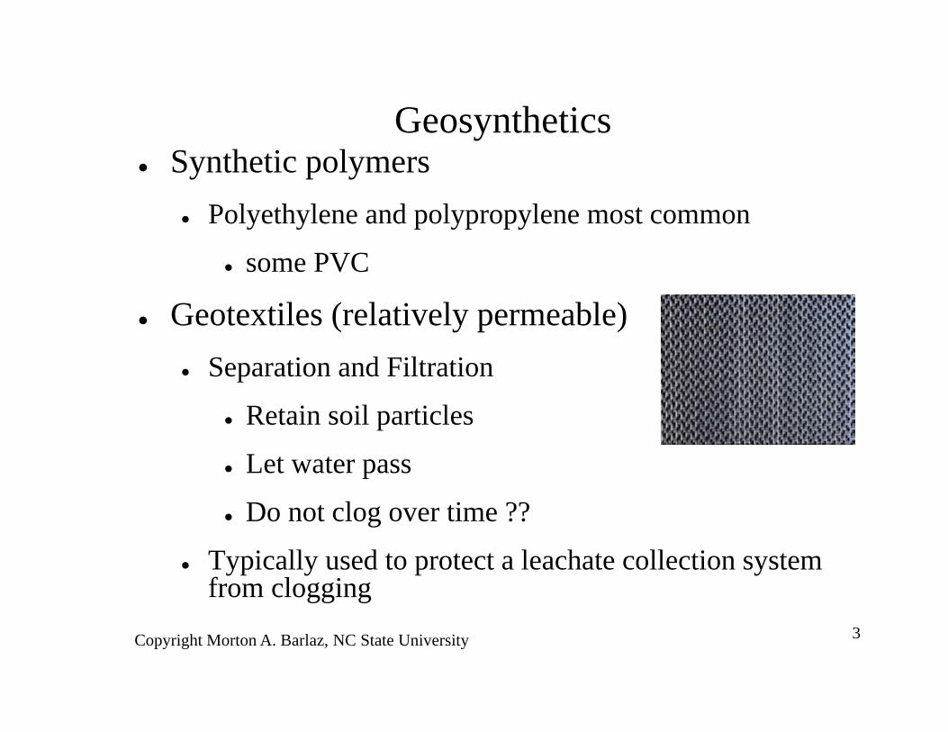
Geosynthetics Synthetic polymers
Polyethylene and polypropylene most common
some PVC
Geotextiles (relatively permeable) Separation and Filtration
Retain soil particles
Let water pass
Do not clog over time ??
Typically used to protect a leachate collection system from clogging
Copyright Morton A. Barlaz, NC State University 4
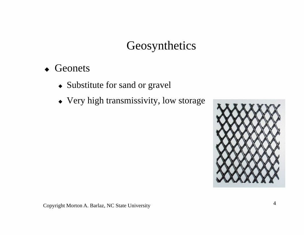
Geosynthetics
Geonets Substitute for sand or gravel
Very high transmissivity, low storage
Copyright Morton A. Barlaz, NC State University 5
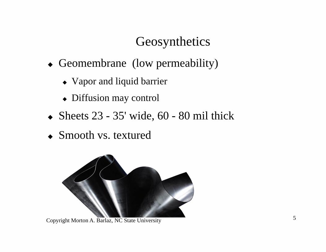
Geosynthetics Geomembrane (low permeability)
Vapor and liquid barrier
Diffusion may control
Sheets 23 - 35' wide, 60 - 80 mil thick
Smooth vs. textured
Copyright Morton A. Barlaz, NC State University 6
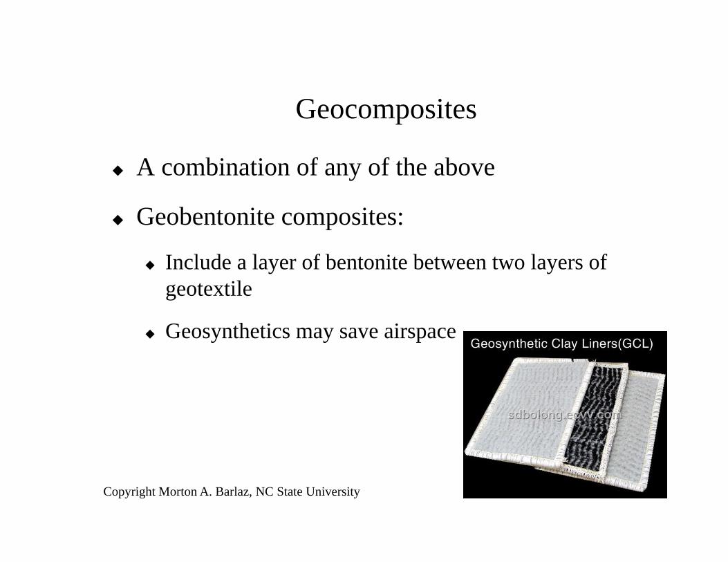
Geocomposites
A combination of any of the above
Geobentonite composites:
Include a layer of bentonite between two layers of geotextile
Geosynthetics may save airspace
Copyright Morton A. Barlaz, NC State University 7
Typical Design Guidelines Subbase
– 6 - 12" thick
– Compact to 95% of maximum density
– K < 10-5 cm/sec
– Slope: 2 - 25% or 1V:4H
– Soil must be rock free
• <3/4” if geomembrane in contact
• <1.5” if clay contact

8
Copyright Morton A. Barlaz, NC State University 9
Secondary LinerFinal Protection Between Waste and
Environment
Clay @ <10-7 cm/sec compacted in 6” lifts
Overlain by a geomembrane
Possibly a geobentonite instead
Must present and follow a QC/QA program
Quality Assurance - 3rd party inspector
Copyright Morton A. Barlaz, NC State University 10
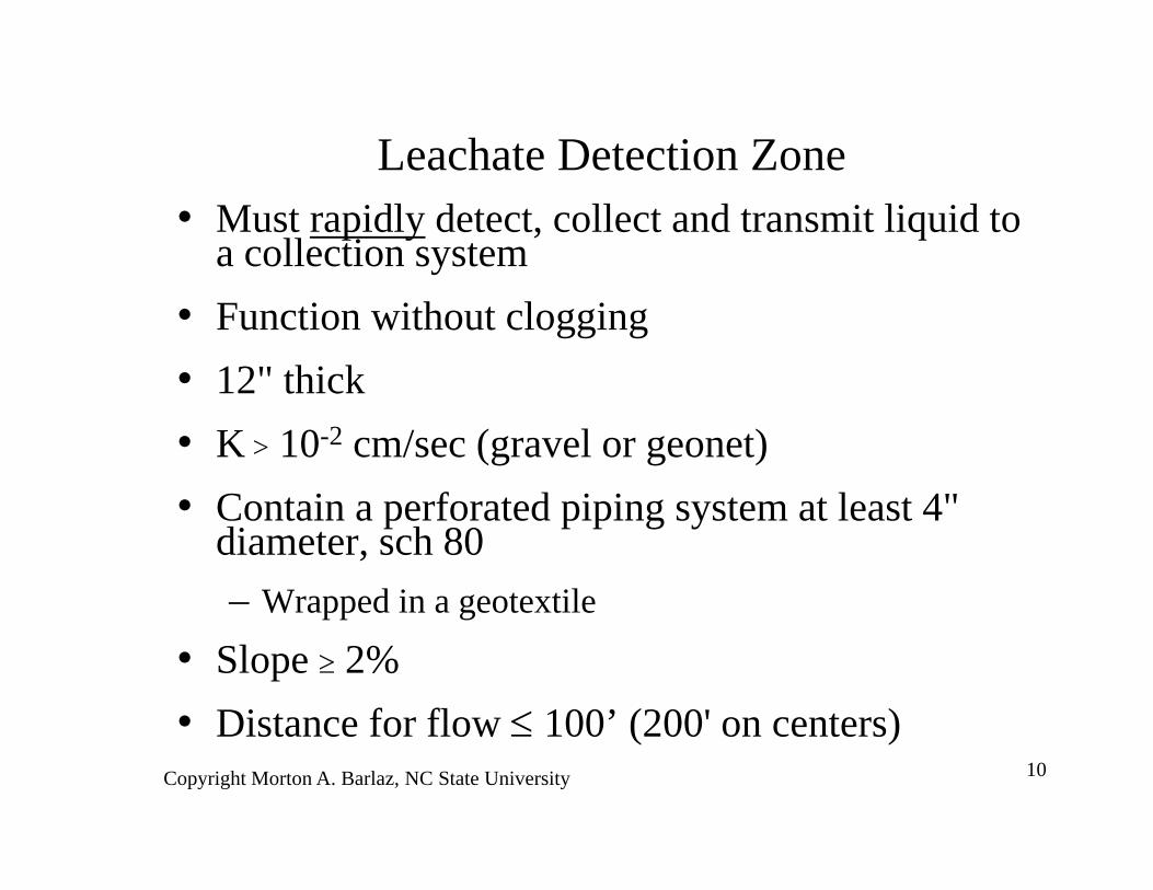
Leachate Detection Zone• Must rapidly detect, collect and transmit liquid to
a collection system• Function without clogging• 12" thick• K > 10-2 cm/sec (gravel or geonet)• Contain a perforated piping system at least 4"
diameter, sch 80– Wrapped in a geotextile
• Slope 2%• Distance for flow 100’ (200' on centers)
Copyright Morton A. Barlaz, NC State University 11
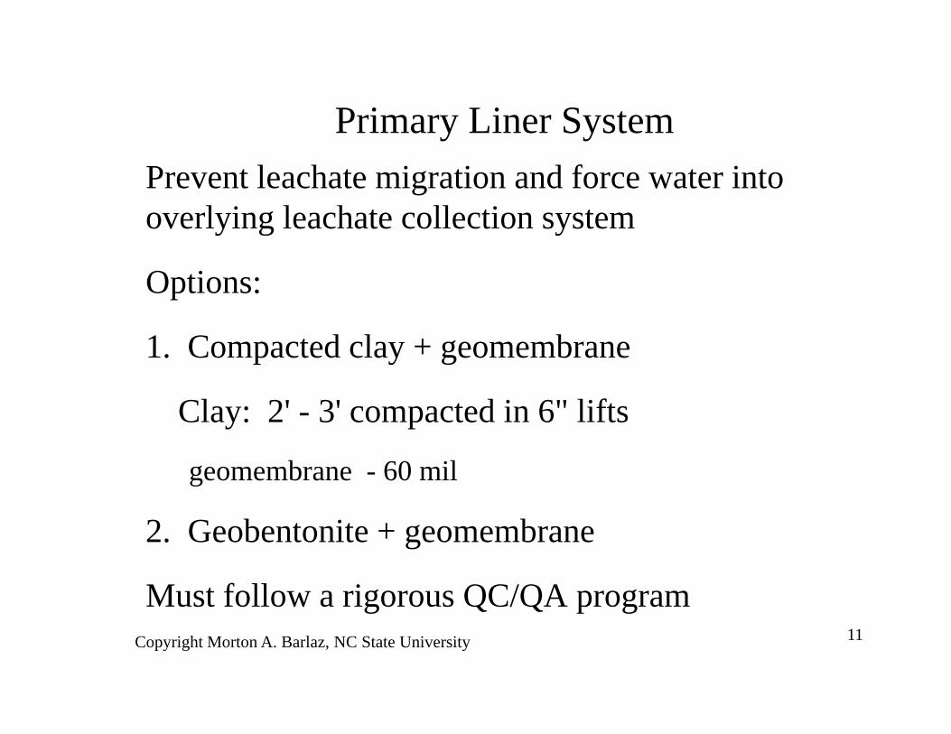
Primary Liner SystemPrevent leachate migration and force water into overlying leachate collection system
Options:
1. Compacted clay + geomembrane
Clay: 2' - 3' compacted in 6" lifts
geomembrane - 60 mil
2. Geobentonite + geomembrane
Must follow a rigorous QC/QA program
Copyright Morton A. Barlaz, NC State University 12
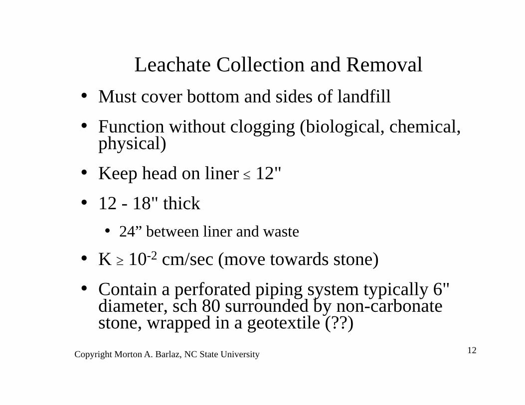
Leachate Collection and Removal• Must cover bottom and sides of landfill• Function without clogging (biological, chemical,
physical)• Keep head on liner 12"• 12 - 18" thick
• 24” between liner and waste
• K 10-2 cm/sec (move towards stone)• Contain a perforated piping system typically 6"
diameter, sch 80 surrounded by non-carbonate stone, wrapped in a geotextile (??)
Copyright Morton A. Barlaz, NC State University 13
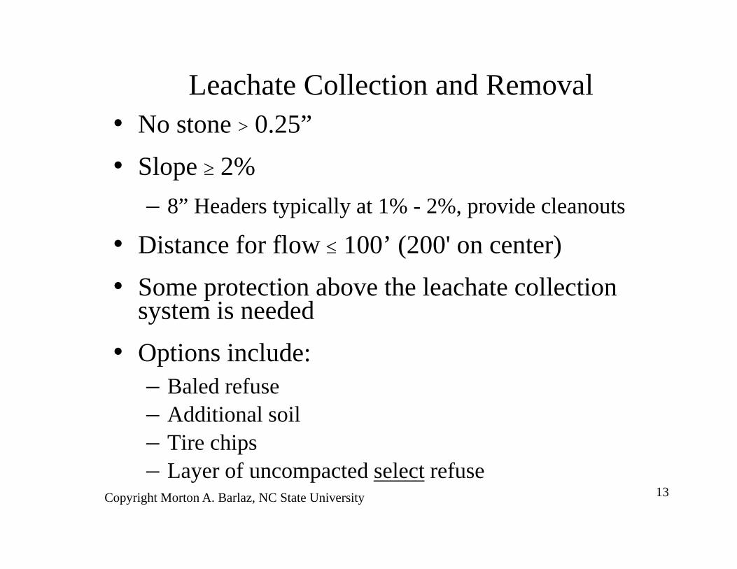
Leachate Collection and Removal• No stone > 0.25”• Slope 2%
– 8” Headers typically at 1% - 2%, provide cleanouts
• Distance for flow 100’ (200' on center)• Some protection above the leachate collection
system is needed• Options include:
– Baled refuse– Additional soil– Tire chips– Layer of uncompacted select refuse
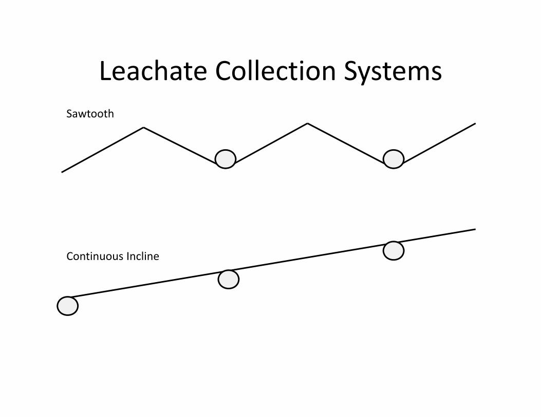
Leachate Collection SystemsSawtooth
Continuous Incline
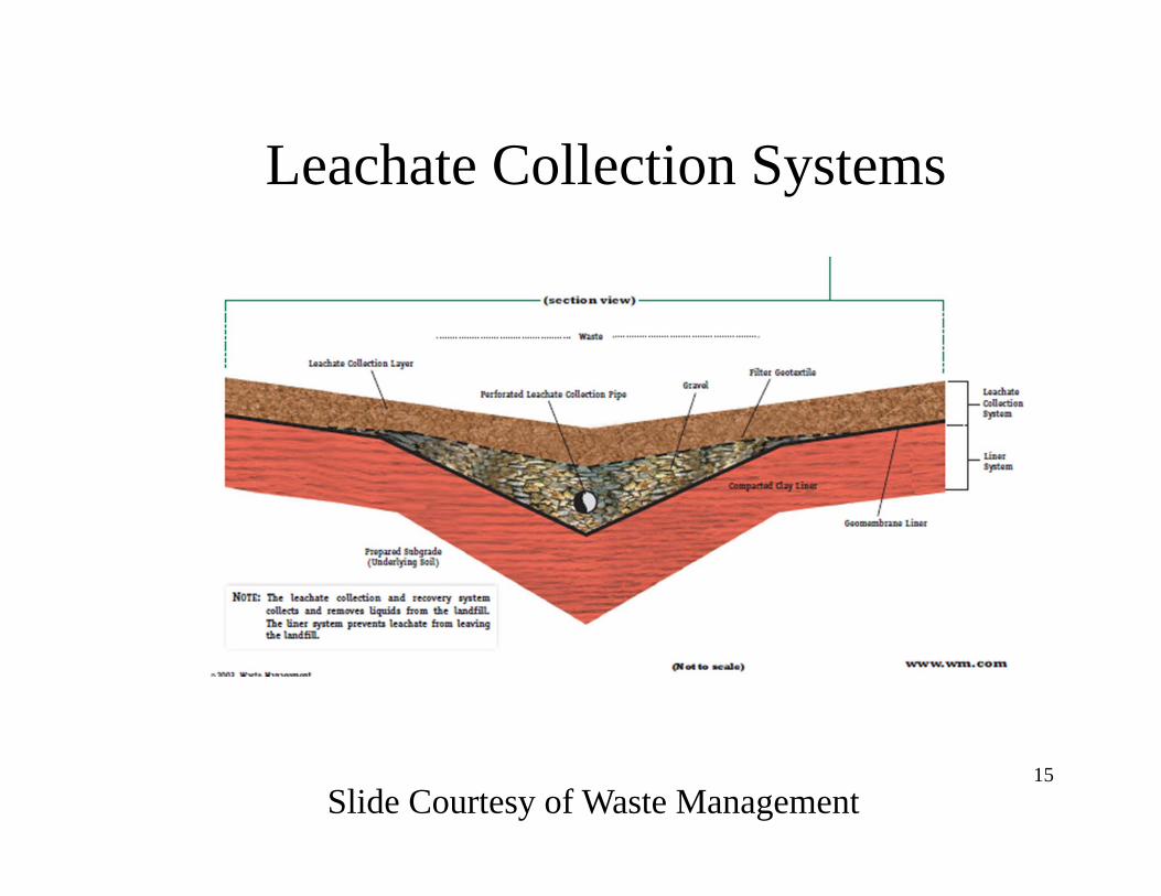
Leachate Collection Systems
15Slide Courtesy of Waste Management
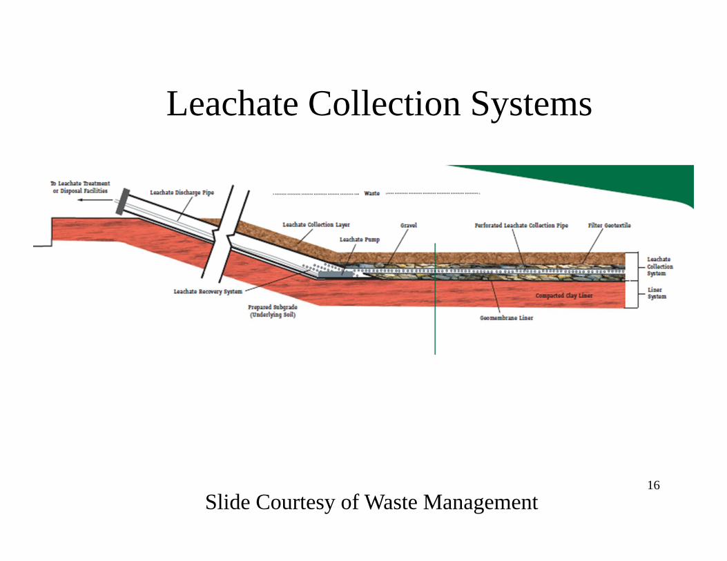
Leachate Collection Systems
16Slide Courtesy of Waste Management
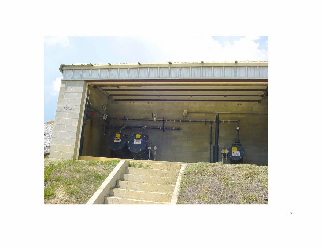
17
Copyright Morton A. Barlaz, NC State University 18
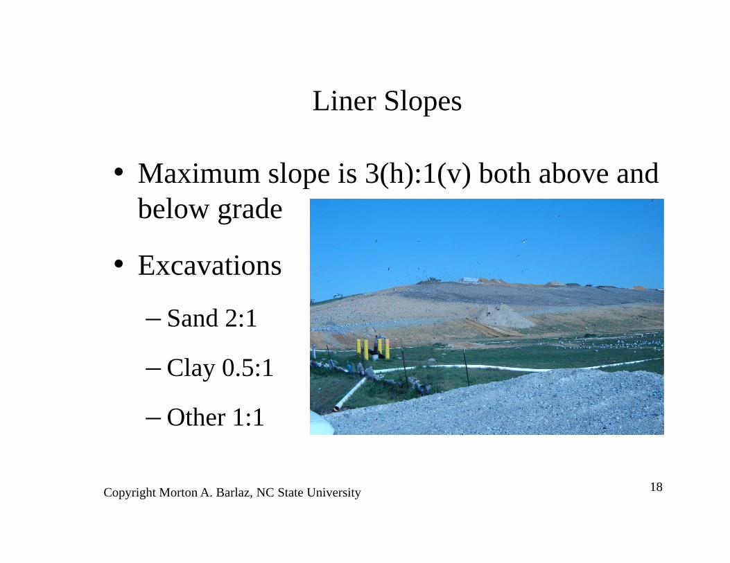
• Maximum slope is 3(h):1(v) both above and below grade
• Excavations
– Sand 2:1
– Clay 0.5:1
– Other 1:1
Liner Slopes
Copyright Morton A. Barlaz, NC State University 19
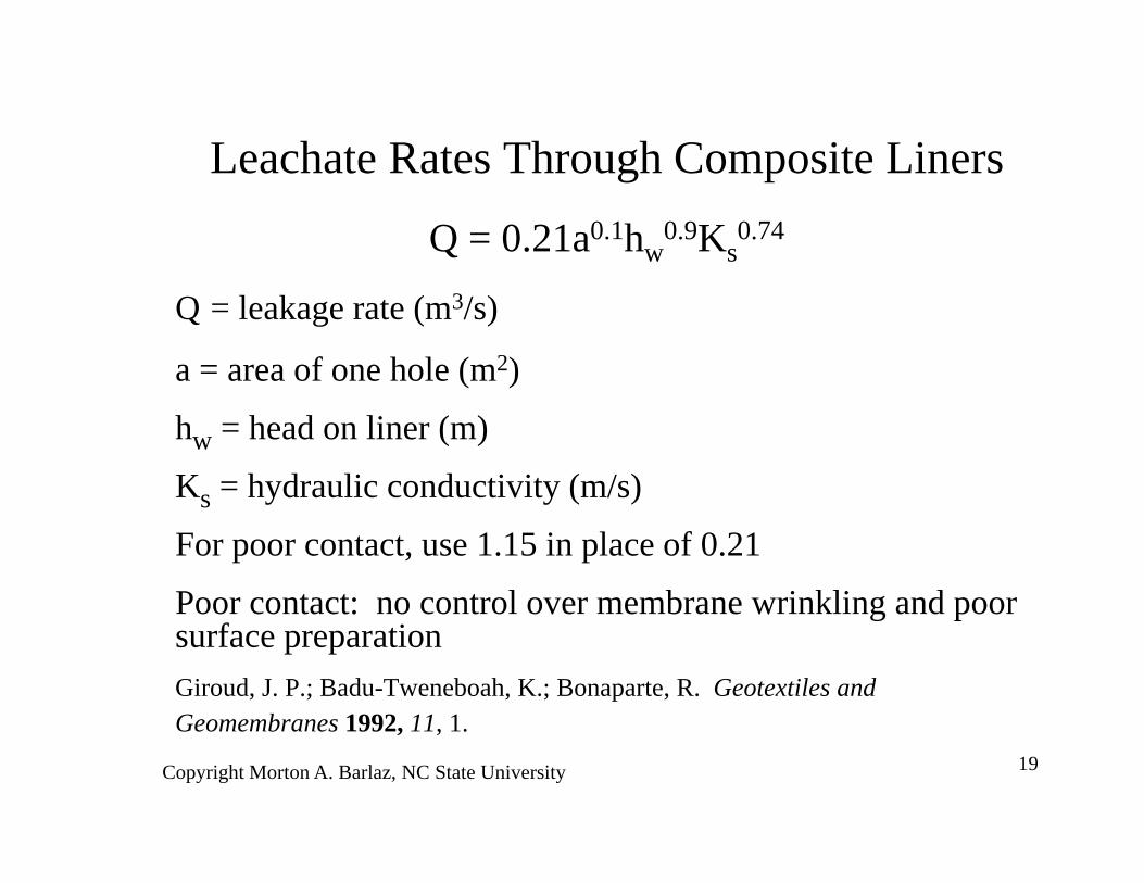
Q = 0.21a0.1hw0.9Ks
0.74
Q = leakage rate (m3/s)
a = area of one hole (m2)
hw = head on liner (m)
Ks = hydraulic conductivity (m/s)
For poor contact, use 1.15 in place of 0.21
Poor contact: no control over membrane wrinkling and poor surface preparationGiroud, J. P.; Badu-Tweneboah, K.; Bonaparte, R. Geotextiles and Geomembranes 1992, 11, 1.
Leachate Rates Through Composite Liners
Copyright Morton A. Barlaz, NC State University 20
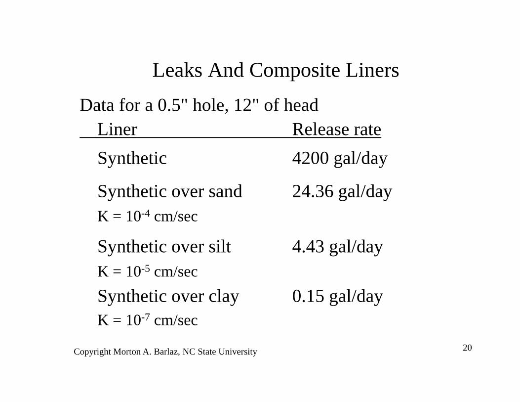
Leaks And Composite LinersData for a 0.5" hole, 12" of head
Liner Release rateSynthetic 4200 gal/day
Synthetic over sand 24.36 gal/dayK = 10-4 cm/sec
Synthetic over silt 4.43 gal/dayK = 10-5 cm/secSynthetic over clay 0.15 gal/dayK = 10-7 cm/sec
Copyright Morton A. Barlaz, NC State University 21
Geomembrane Leak Testing• 20% of leaks were in the side slopes at sites tested• 87% of leaks were at the seams• 13% in parent material
– Dropped tools– Cigarette burns

Copyright Morton A. Barlaz, NC State University 22
Geomembrane Leak Testing• Critical factors:
– Corners, sumps, penetrations
• Methods are available for leak detection– Visual inspection– Pressure or vacuum testing of seams– electric leak detection
Copyright Morton A. Barlaz, NC State University 23
Final CoverFunctions:
– keep water out
– control runoff
– separate the waste from plants and animals
– gas collection/odor control
Complicating Factors:– plant root penetration
– freeze/thaw
– vehicle haul roads
– differential settlement

Copyright Morton A. Barlaz, NC State University 24
Cover Cross Section
1 ft. soil/gas distribution
2 ft. clay
6 in. top soil/ additional soil for freeze protection
waste
1 ft. drainage layer0.06 in. plastic liner

Copyright Morton A. Barlaz, NC State University 25
Clays• Hard to compact over sand or refuse
• Desiccate and shrink from both top and bottom
• Thin layers (even 18") of cover do not prevent desiccation
• Final grade > 3% on top, slopes @ 3:1
Copyright Morton A. Barlaz, NC State University 26
Vegetation Objectives
Stabilize soil
Minimize erosion
Promote evapotranspiration
Next possible planting season
> 70% ground cover
No deep rooted plants or shrubs
Copyright Morton A. Barlaz, NC State University 27
Additional Considerations• Practice is to place final cover once site (or cell) is full • Differential settlement will cause cracks in clay,
geomembranes are more resistant and recommended• Ideal - use an intermediate cover until settlement is
complete– Financial implications
– Recover airspace– Less maintenance
– low permeability desirable for gas collection– biocover alternatives
Copyright Morton A. Barlaz, NC State University 28
Alternate (ET) Covers
• Sufficient soil to retain water until it evaporates
• Ongoing research
• requires regulatory approval
Copyright Morton A. Barlaz, NC State University 29
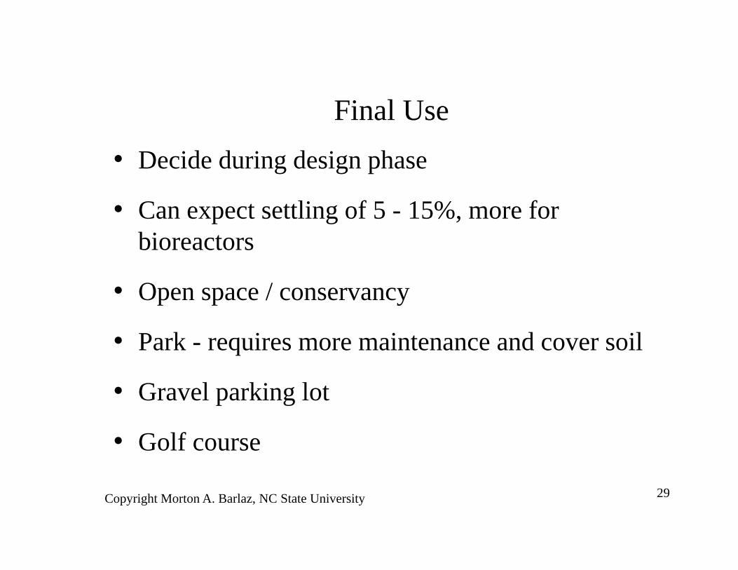
Final Use• Decide during design phase
• Can expect settling of 5 - 15%, more for bioreactors
• Open space / conservancy
• Park - requires more maintenance and cover soil
• Gravel parking lot
• Golf course

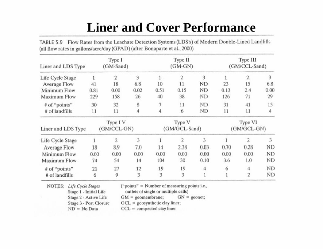
Liner and Cover Performance
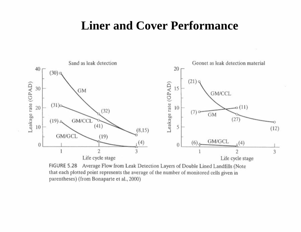
Liner and Cover Performance
Liner and Cover Performance