geosynthetics engineering: in theory and … 54.pdf · geosynthetics engineering: in theory and...
TRANSCRIPT
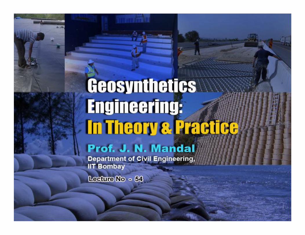
GEOSYNTHETICS ENGINEERING: IN THEORY AND PRACTICE
Prof. J. N. Mandal
Department of Civil Engineering, IIT Bombay, Powai , Mumbai 400076, India. Tel.022-25767328email: [email protected]
Prof. J. N. Mandal, Department of Civil Engineering, IIT Bombay
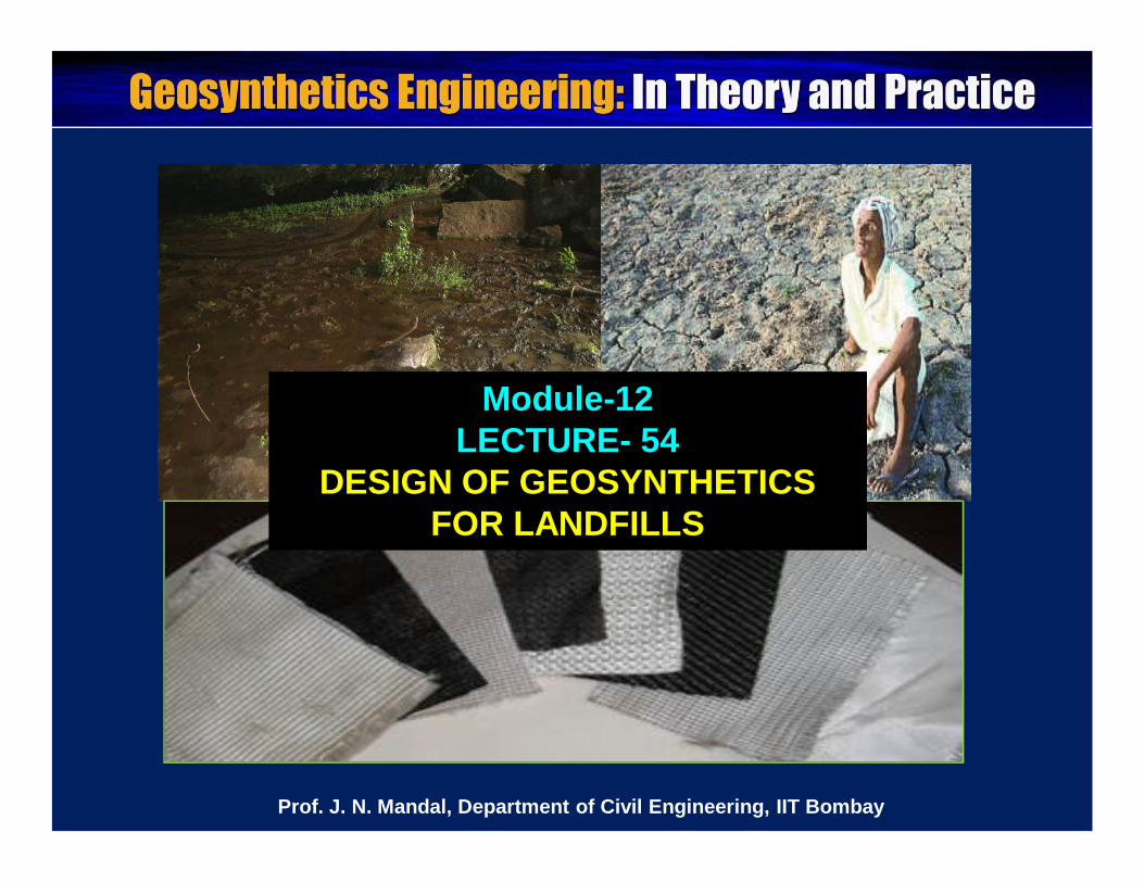
Module-12LECTURE- 54
DESIGN OF GEOSYNTHETICS FOR LANDFILLS
Prof. J. N. Mandal, Department of Civil Engineering, IIT Bombay
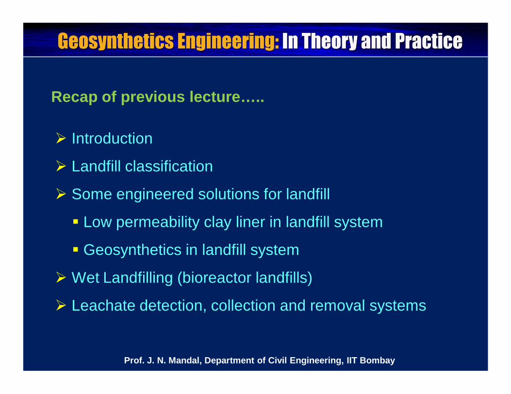
Introduction
Landfill classification
Some engineered solutions for landfill
Low permeability clay liner in landfill system
Geosynthetics in landfill system
Wet Landfilling (bioreactor landfills)
Leachate detection, collection and removal systems
Prof. J. N. Mandal, Department of Civil Engineering, IIT Bombay
Recap of previous lecture…..
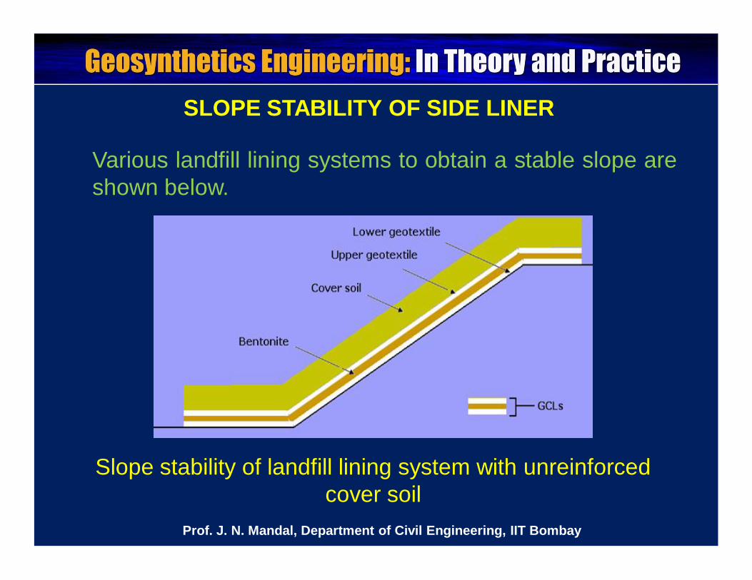
SLOPE STABILITY OF SIDE LINER
Various landfill lining systems to obtain a stable slope areshown below.
Slope stability of landfill lining system with unreinforced cover soil
Prof. J. N. Mandal, Department of Civil Engineering, IIT Bombay
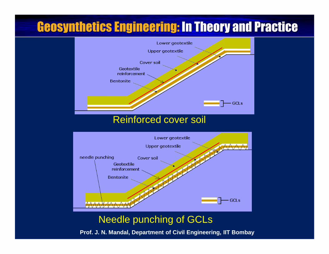
Reinforced cover soil
Needle punching of GCLsProf. J. N. Mandal, Department of Civil Engineering, IIT Bombay
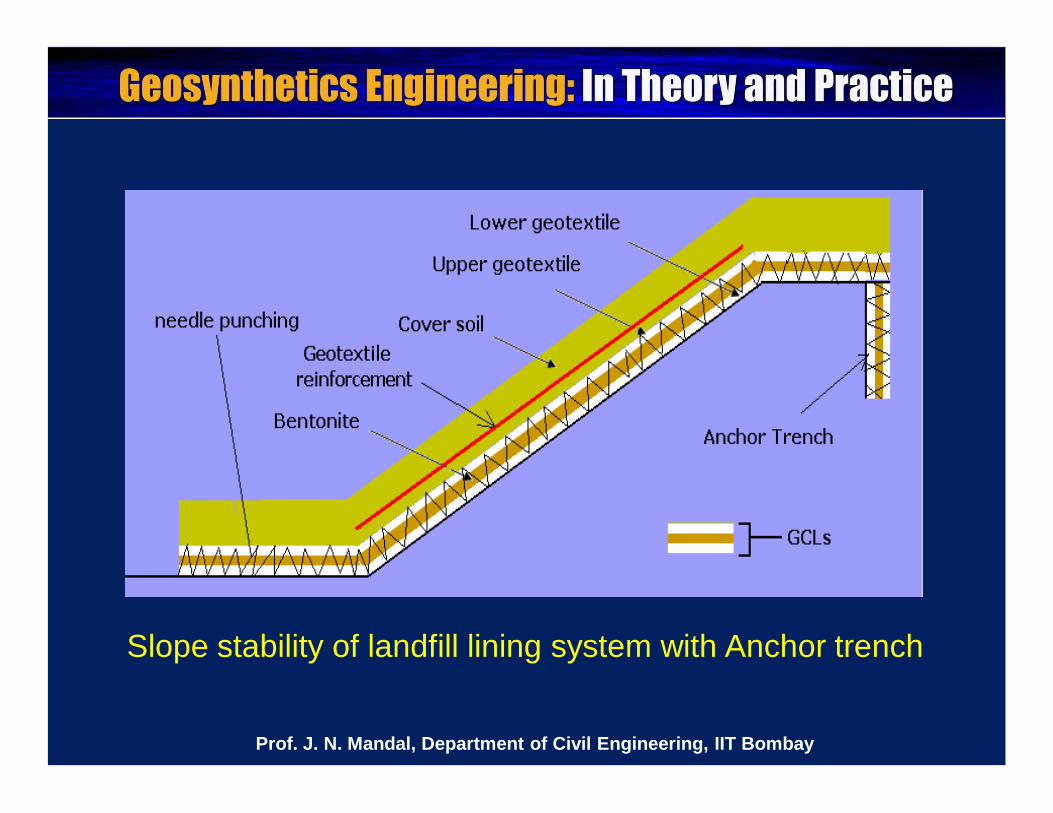
Slope stability of landfill lining system with Anchor trench
Prof. J. N. Mandal, Department of Civil Engineering, IIT Bombay
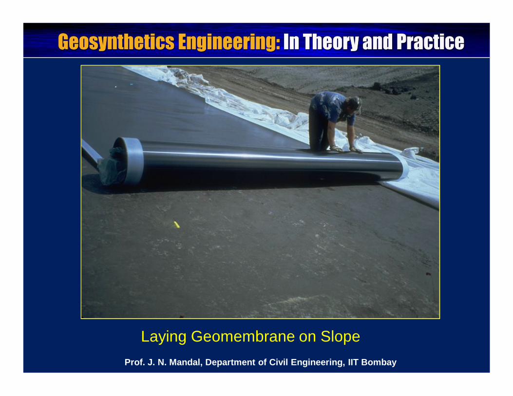
Laying Geomembrane on SlopeProf. J. N. Mandal, Department of Civil Engineering, IIT Bombay
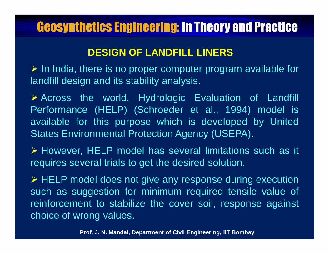
DESIGN OF LANDFILL LINERS In India, there is no proper computer program available forlandfill design and its stability analysis.
Across the world, Hydrologic Evaluation of LandfillPerformance (HELP) (Schroeder et al., 1994) model isavailable for this purpose which is developed by UnitedStates Environmental Protection Agency (USEPA).
However, HELP model has several limitations such as itrequires several trials to get the desired solution.
HELP model does not give any response during executionsuch as suggestion for minimum required tensile value ofreinforcement to stabilize the cover soil, response againstchoice of wrong values.
Prof. J. N. Mandal, Department of Civil Engineering, IIT Bombay
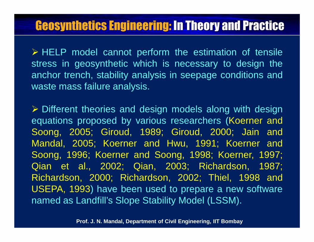
HELP model cannot perform the estimation of tensilestress in geosynthetic which is necessary to design theanchor trench, stability analysis in seepage conditions andwaste mass failure analysis.
Different theories and design models along with designequations proposed by various researchers (Koerner andSoong, 2005; Giroud, 1989; Giroud, 2000; Jain andMandal, 2005; Koerner and Hwu, 1991; Koerner andSoong, 1996; Koerner and Soong, 1998; Koerner, 1997;Qian et al., 2002; Qian, 2003; Richardson, 1987;Richardson, 2000; Richardson, 2002; Thiel, 1998 andUSEPA, 1993) have been used to prepare a new softwarenamed as Landfill’s Slope Stability Model (LSSM).
Prof. J. N. Mandal, Department of Civil Engineering, IIT Bombay
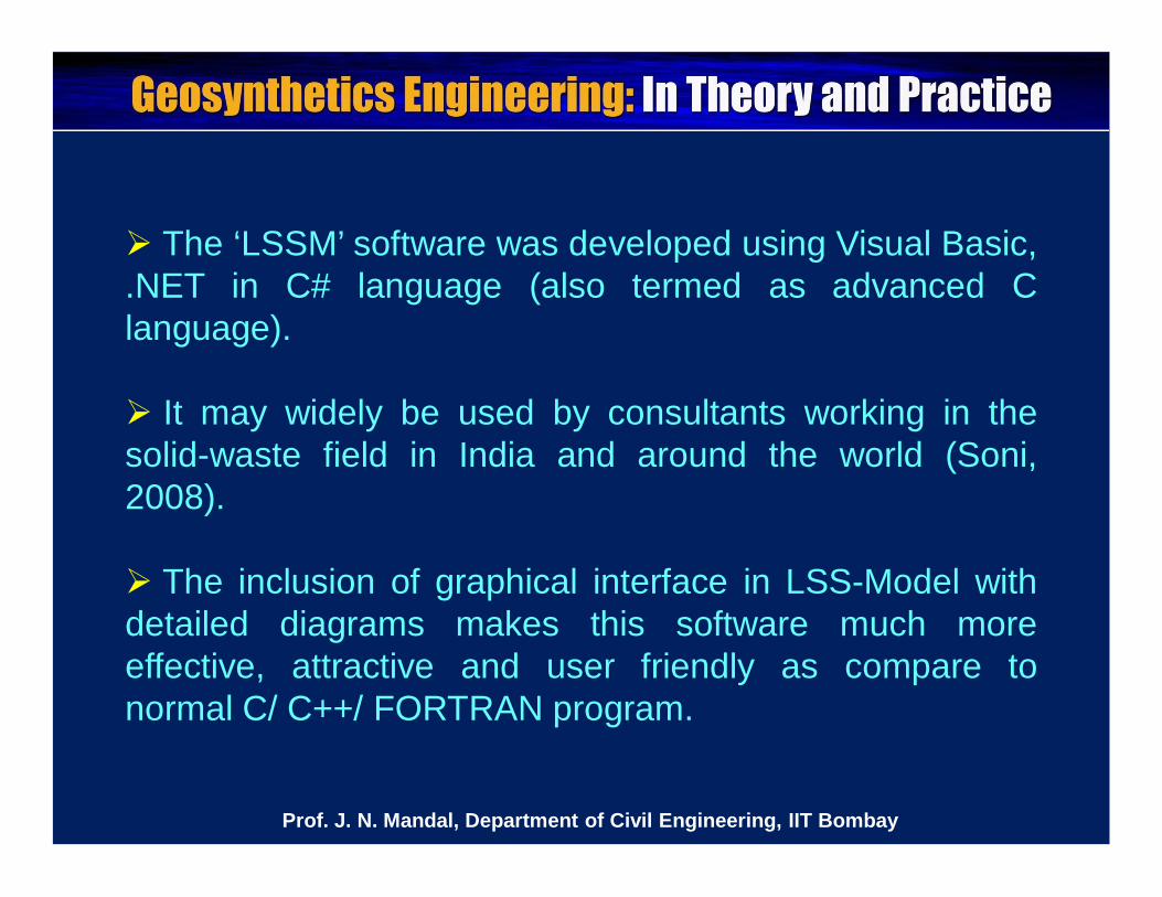
The ‘LSSM’ software was developed using Visual Basic,.NET in C# language (also termed as advanced Clanguage).
It may widely be used by consultants working in thesolid-waste field in India and around the world (Soni,2008).
The inclusion of graphical interface in LSS-Model withdetailed diagrams makes this software much moreeffective, attractive and user friendly as compare tonormal C/ C++/ FORTRAN program.
Prof. J. N. Mandal, Department of Civil Engineering, IIT Bombay
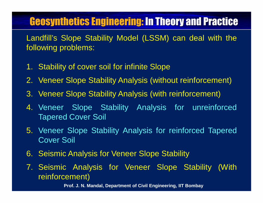
Landfill’s Slope Stability Model (LSSM) can deal with thefollowing problems:
1. Stability of cover soil for infinite Slope
2. Veneer Slope Stability Analysis (without reinforcement)
3. Veneer Slope Stability Analysis (with reinforcement)
4. Veneer Slope Stability Analysis for unreinforcedTapered Cover Soil
5. Veneer Slope Stability Analysis for reinforced TaperedCover Soil
6. Seismic Analysis for Veneer Slope Stability
7. Seismic Analysis for Veneer Slope Stability (Withreinforcement)
Prof. J. N. Mandal, Department of Civil Engineering, IIT Bombay
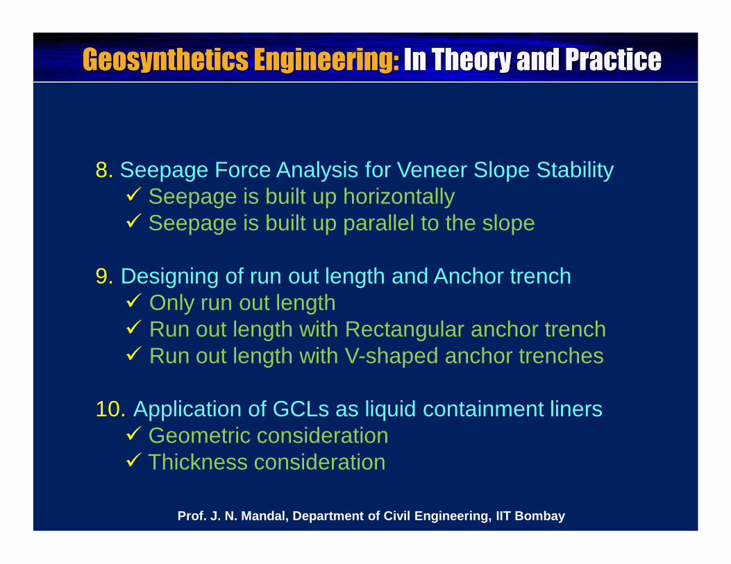
8. Seepage Force Analysis for Veneer Slope Stability Seepage is built up horizontally Seepage is built up parallel to the slope
9. Designing of run out length and Anchor trench Only run out length Run out length with Rectangular anchor trench Run out length with V-shaped anchor trenches
10. Application of GCLs as liquid containment liners Geometric consideration Thickness consideration
Prof. J. N. Mandal, Department of Civil Engineering, IIT Bombay
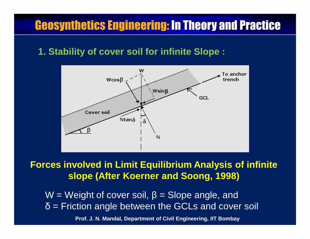
1. Stability of cover soil for infinite Slope :
Forces involved in Limit Equilibrium Analysis of infinite slope (After Koerner and Soong, 1998)
W = Weight of cover soil, β = Slope angle, and δ = Friction angle between the GCLs and cover soil
Prof. J. N. Mandal, Department of Civil Engineering, IIT Bombay
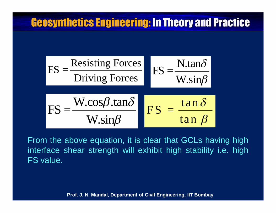
Resisting ForcesFS =Driving Forces
N.tanFS =W.sin
W.cos .tanFS =W.sin
tanF S =tan
From the above equation, it is clear that GCLs having highinterface shear strength will exhibit high stability i.e. highFS value.
Prof. J. N. Mandal, Department of Civil Engineering, IIT Bombay
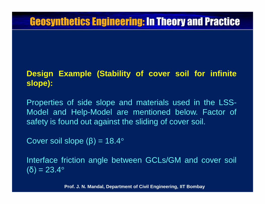
Design Example (Stability of cover soil for infiniteslope):
Properties of side slope and materials used in the LSS-Model and Help-Model are mentioned below. Factor ofsafety is found out against the sliding of cover soil.
Cover soil slope (β) = 18.4°
Interface friction angle between GCLs/GM and cover soil(δ) = 23.4°
Prof. J. N. Mandal, Department of Civil Engineering, IIT Bombay
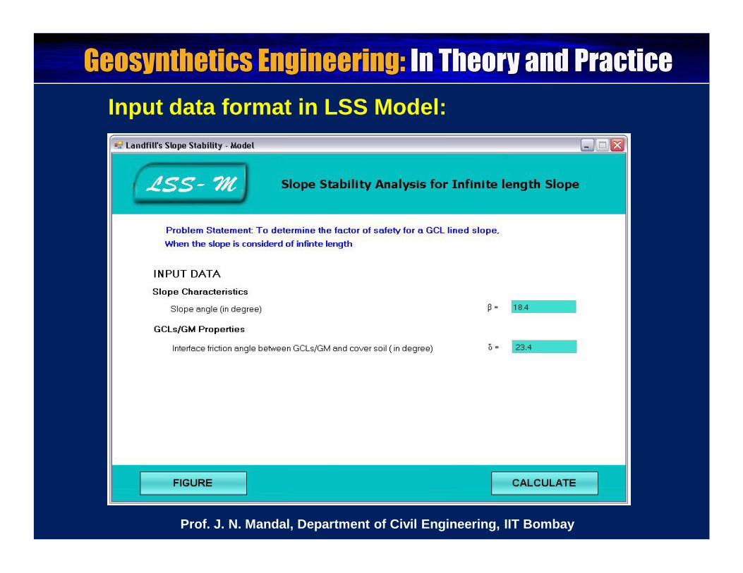
Input data format in LSS Model:
Prof. J. N. Mandal, Department of Civil Engineering, IIT Bombay
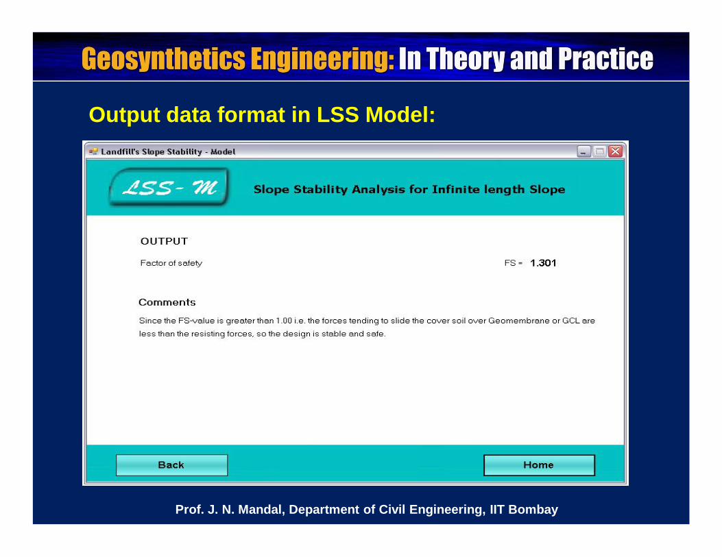
Output data format in LSS Model:
Prof. J. N. Mandal, Department of Civil Engineering, IIT Bombay
Results of LSS-Model were found to be similar ascompared to Help-Model.
Case Help-Model LSS-ModelInfinite length slope
stability analysisNo such options
is available FS = 1.301
Prof. J. N. Mandal, Department of Civil Engineering, IIT Bombay
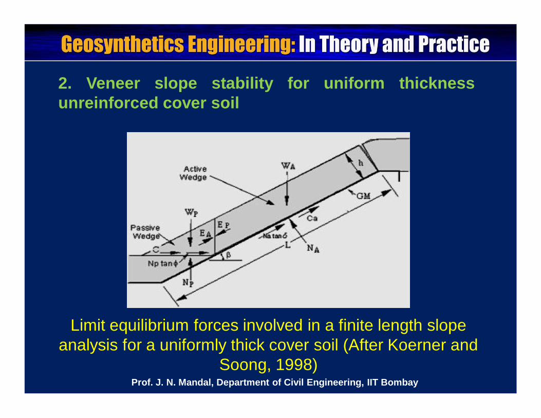
2. Veneer slope stability for uniform thicknessunreinforced cover soil
Limit equilibrium forces involved in a finite length slope analysis for a uniformly thick cover soil (After Koerner and
Soong, 1998)Prof. J. N. Mandal, Department of Civil Engineering, IIT Bombay
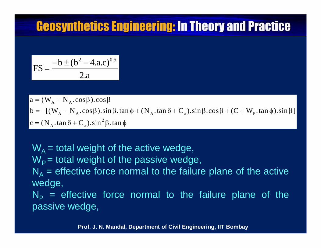
2 0.5b (b 4.a.c)FS2.a
A A
A A A a P2
A a
a (W N .cos ).cosb [(W N .cos ).sin . tan (N . tan C ).sin .cos (C W .tan ).sin ]
c (N . tan C ).sin . tan
WA = total weight of the active wedge,WP = total weight of the passive wedge,NA = effective force normal to the failure plane of the activewedge,NP = effective force normal to the failure plane of thepassive wedge,
Prof. J. N. Mandal, Department of Civil Engineering, IIT Bombay
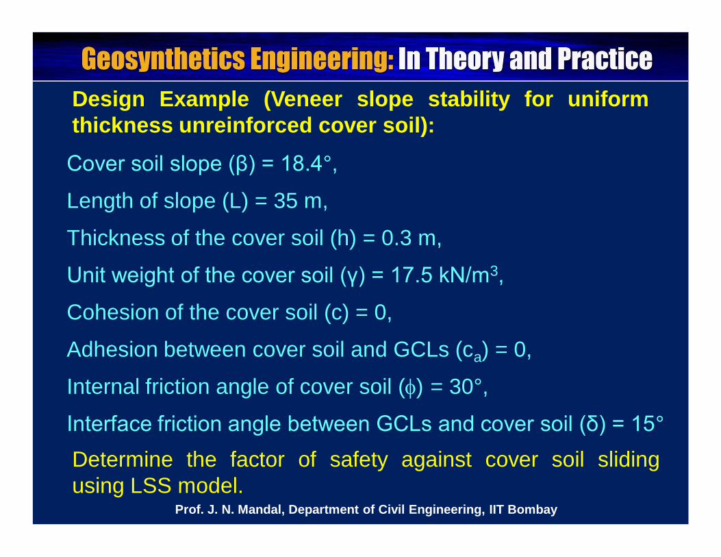
Design Example (Veneer slope stability for uniformthickness unreinforced cover soil):
Determine the factor of safety against cover soil slidingusing LSS model.
Cover soil slope (β) = 18.4°,
Length of slope (L) = 35 m,
Thickness of the cover soil (h) = 0.3 m,
Unit weight of the cover soil (γ) = 17.5 kN/m3,
Cohesion of the cover soil (c) = 0,
Adhesion between cover soil and GCLs (ca) = 0,
Internal friction angle of cover soil () = 30°,
Interface friction angle between GCLs and cover soil (δ) = 15°
Prof. J. N. Mandal, Department of Civil Engineering, IIT Bombay
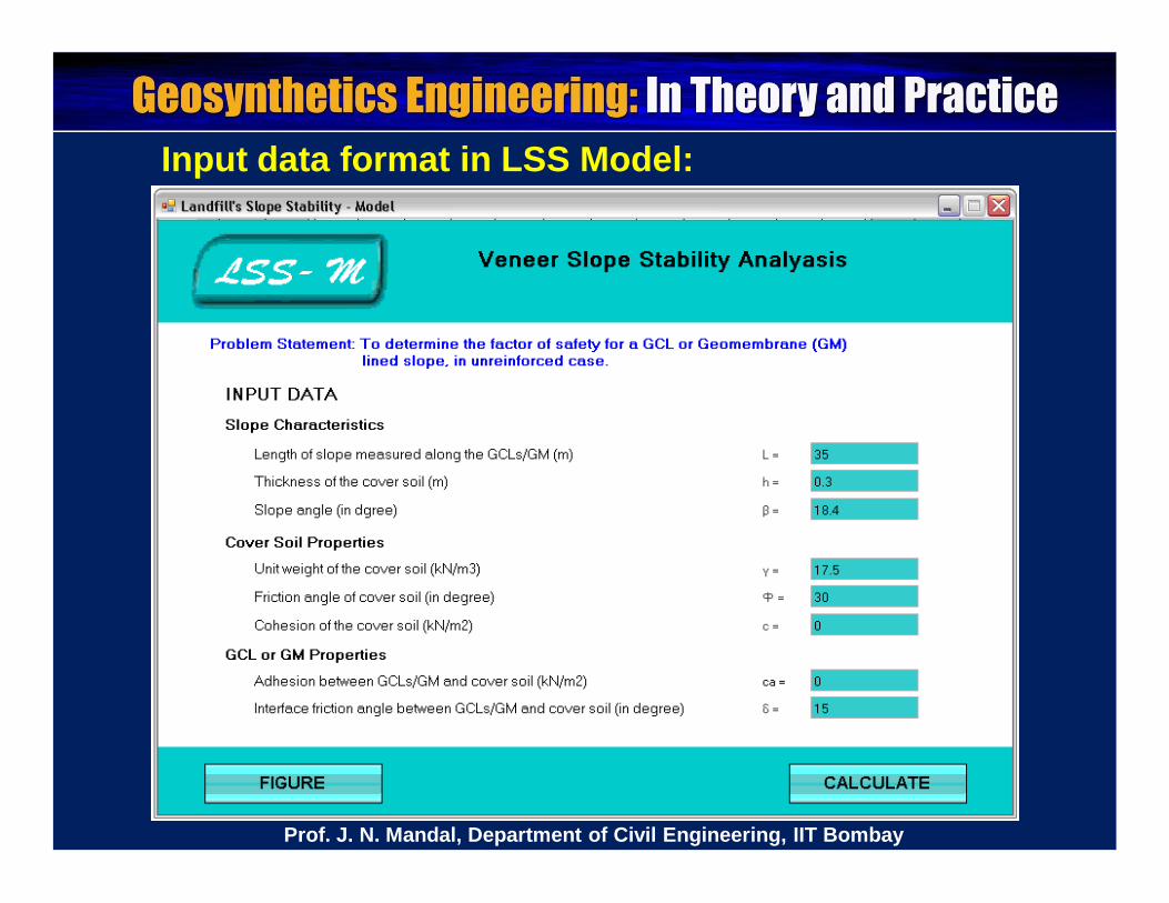
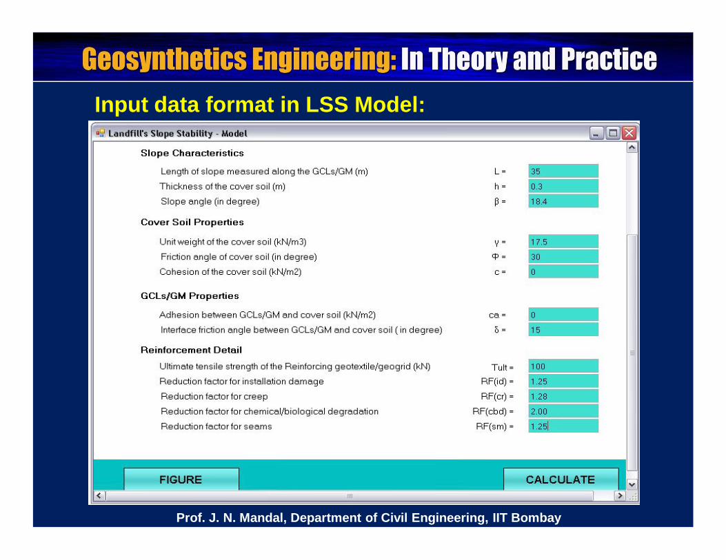
Input data format in LSS Model:
Prof. J. N. Mandal, Department of Civil Engineering, IIT Bombay
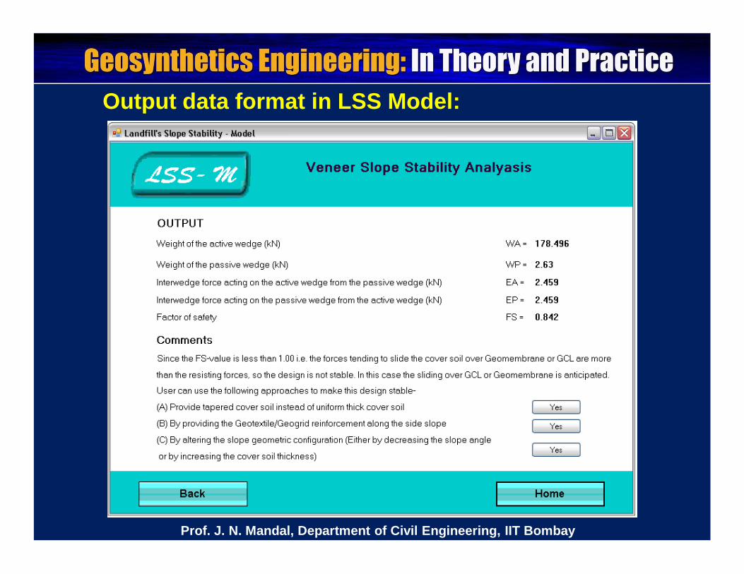
Output data format in LSS Model:
Prof. J. N. Mandal, Department of Civil Engineering, IIT Bombay
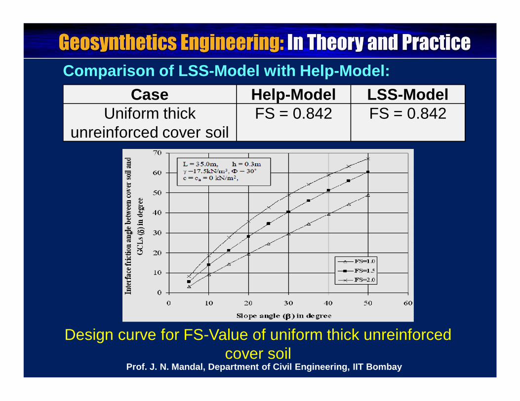
Case Help-Model LSS-ModelUniform thick
unreinforced cover soilFS = 0.842 FS = 0.842
Comparison of LSS-Model with Help-Model:
Design curve for FS-Value of uniform thick unreinforced cover soil
Prof. J. N. Mandal, Department of Civil Engineering, IIT Bombay
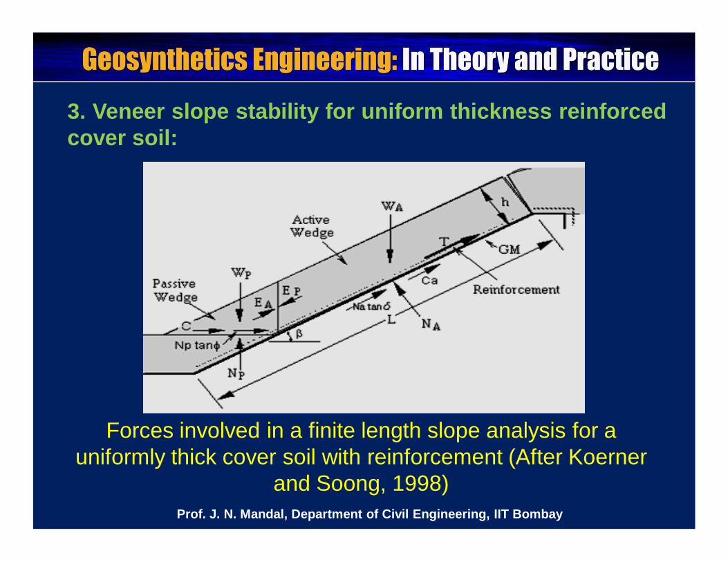
3. Veneer slope stability for uniform thickness reinforcedcover soil:
Forces involved in a finite length slope analysis for a uniformly thick cover soil with reinforcement (After Koerner
and Soong, 1998)Prof. J. N. Mandal, Department of Civil Engineering, IIT Bombay
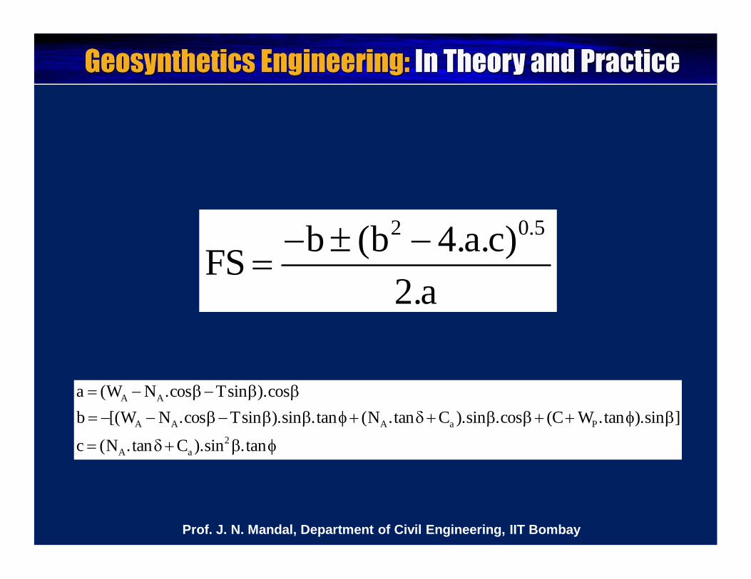
2 0.5b (b 4.a.c)FS2.a
A A
A A A a P2
A a
a (W N .cos Tsin ).cosb [(W N .cos Tsin ).sin .tan (N .tan C ).sin .cos (C W .tan ).sin ]
c (N .tan C ).sin .tan
Prof. J. N. Mandal, Department of Civil Engineering, IIT Bombay
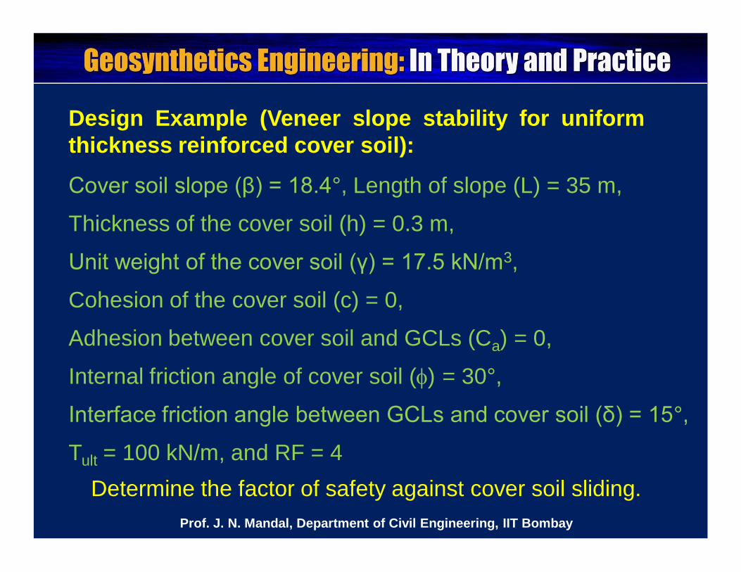
Design Example (Veneer slope stability for uniformthickness reinforced cover soil):
Cover soil slope (β) = 18.4°, Length of slope (L) = 35 m,
Thickness of the cover soil (h) = 0.3 m,
Unit weight of the cover soil (γ) = 17.5 kN/m3,
Cohesion of the cover soil (c) = 0,
Adhesion between cover soil and GCLs (Ca) = 0,
Internal friction angle of cover soil () = 30°,
Interface friction angle between GCLs and cover soil (δ) = 15°,
Tult = 100 kN/m, and RF = 4Determine the factor of safety against cover soil sliding.
Prof. J. N. Mandal, Department of Civil Engineering, IIT Bombay
Input data format in LSS Model:
Prof. J. N. Mandal, Department of Civil Engineering, IIT Bombay
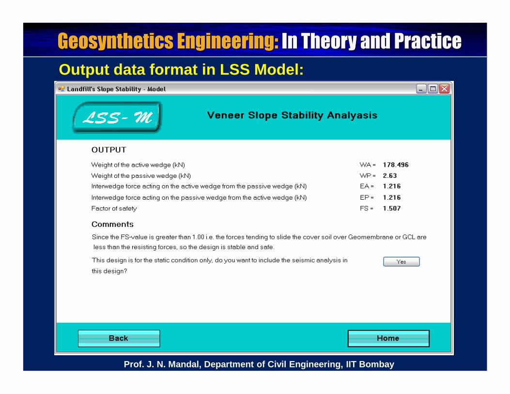
Output data format in LSS Model:
Prof. J. N. Mandal, Department of Civil Engineering, IIT Bombay
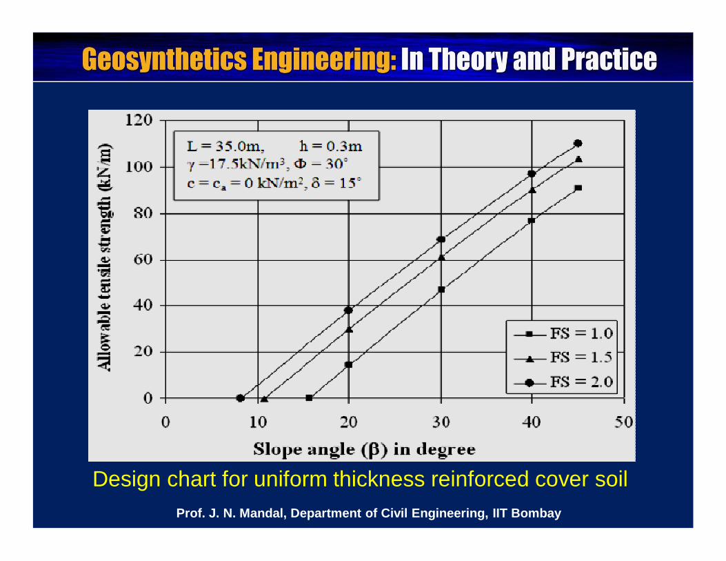
Design chart for uniform thickness reinforced cover soilProf. J. N. Mandal, Department of Civil Engineering, IIT Bombay
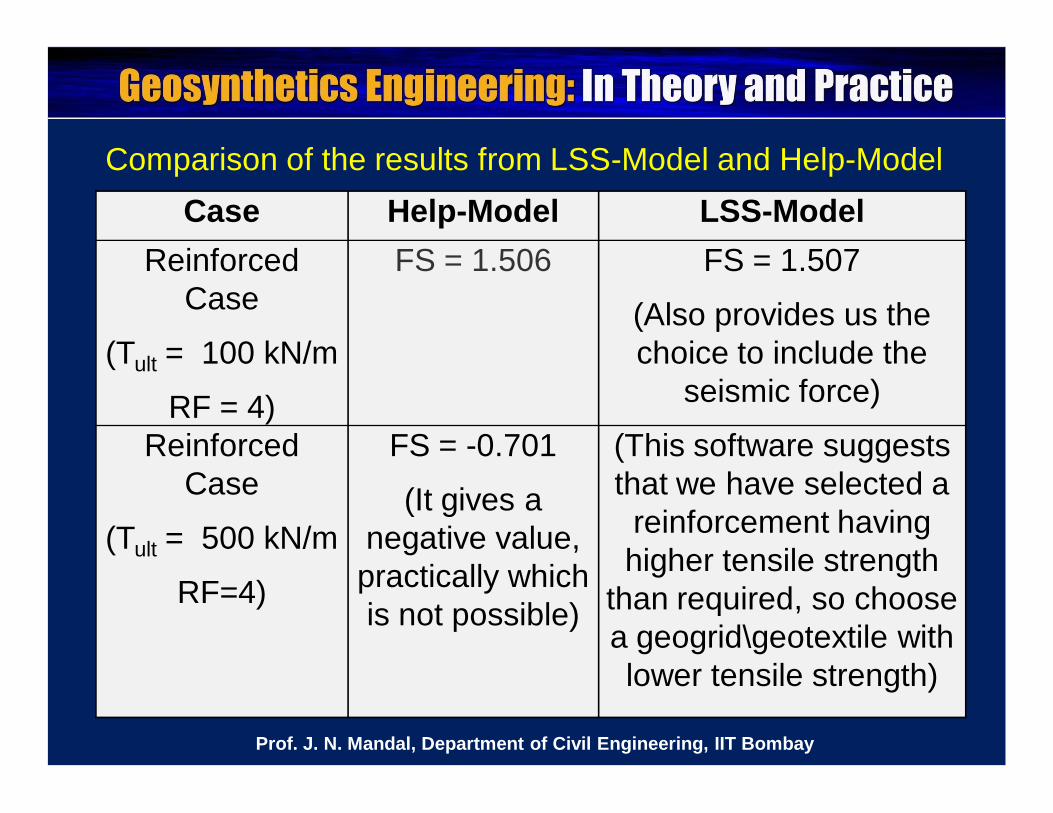
Case Help-Model LSS-ModelReinforced
Case
(Tult = 100 kN/m
RF = 4)
FS = 1.506 FS = 1.507
(Also provides us the choice to include the
seismic force)
Reinforced Case
(Tult = 500 kN/m
RF=4)
FS = -0.701
(It gives a negative value,
practically which is not possible)
(This software suggests that we have selected a
reinforcement having higher tensile strength
than required, so choose a geogrid\geotextile with lower tensile strength)
Comparison of the results from LSS-Model and Help-Model
Prof. J. N. Mandal, Department of Civil Engineering, IIT Bombay

4. Seismic analysis in Veneer slope stability for uniformthick cover soil (without reinforcement)
Limit equilibrium forces involved in pseudo-static analysis(After Qian et al., 2002)
Prof. J. N. Mandal, Department of Civil Engineering, IIT Bombay
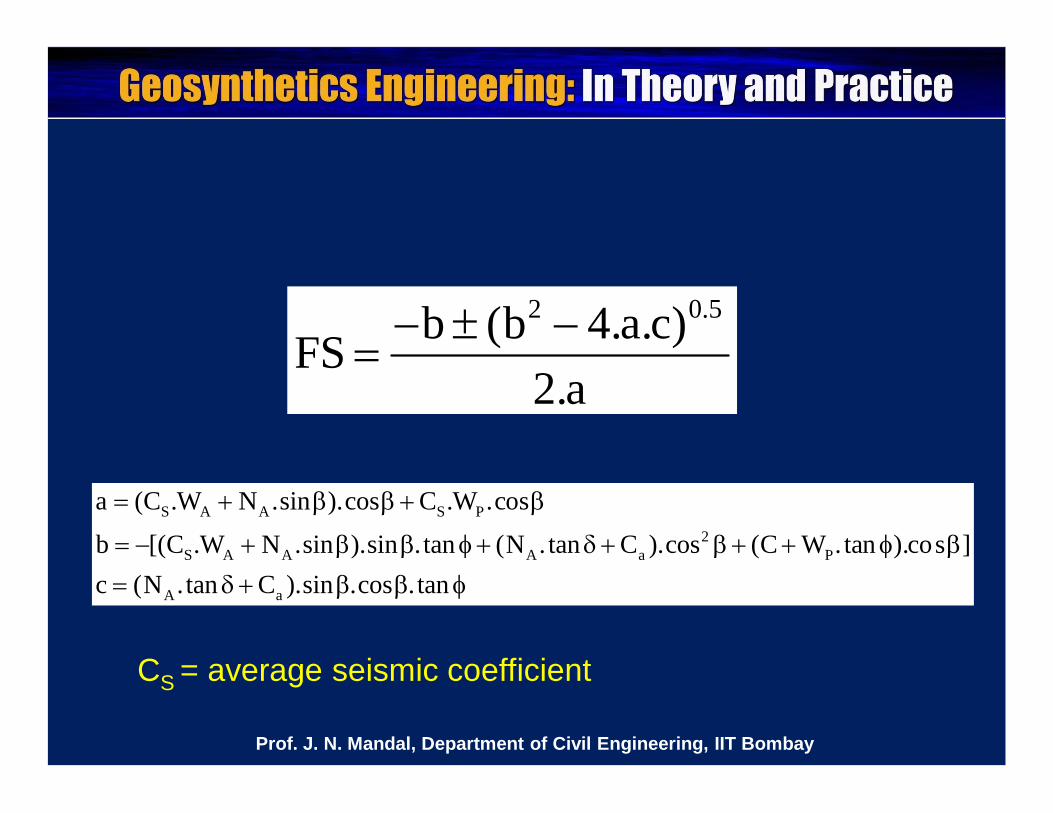
2 0.5b (b 4.a.c)FS2.a
S A A S P2
S A A A a P
A a
a (C .W N .sin ).cos C .W .cos
b [(C .W N .sin ).sin .tan (N .tan C ).cos (C W .tan ).cos ]c (N .tan C ).sin .cos .tan
CS = average seismic coefficient
Prof. J. N. Mandal, Department of Civil Engineering, IIT Bombay
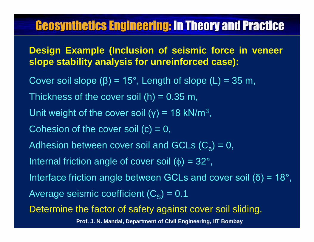
Design Example (Inclusion of seismic force in veneerslope stability analysis for unreinforced case):
Cover soil slope (β) = 15°, Length of slope (L) = 35 m,
Thickness of the cover soil (h) = 0.35 m,
Unit weight of the cover soil (γ) = 18 kN/m3,
Cohesion of the cover soil (c) = 0,
Adhesion between cover soil and GCLs (Ca) = 0,
Internal friction angle of cover soil () = 32°,
Interface friction angle between GCLs and cover soil (δ) = 18°,
Average seismic coefficient (CS) = 0.1 Determine the factor of safety against cover soil sliding.
Prof. J. N. Mandal, Department of Civil Engineering, IIT Bombay
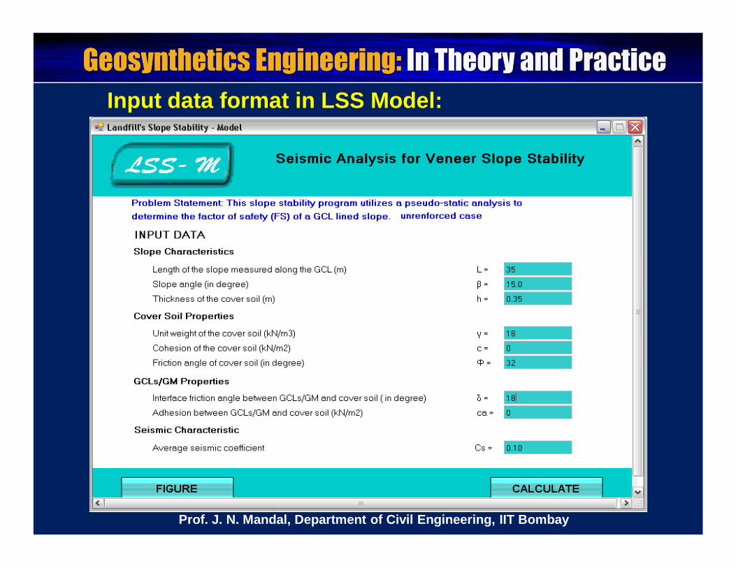
Input data format in LSS Model:
Prof. J. N. Mandal, Department of Civil Engineering, IIT Bombay
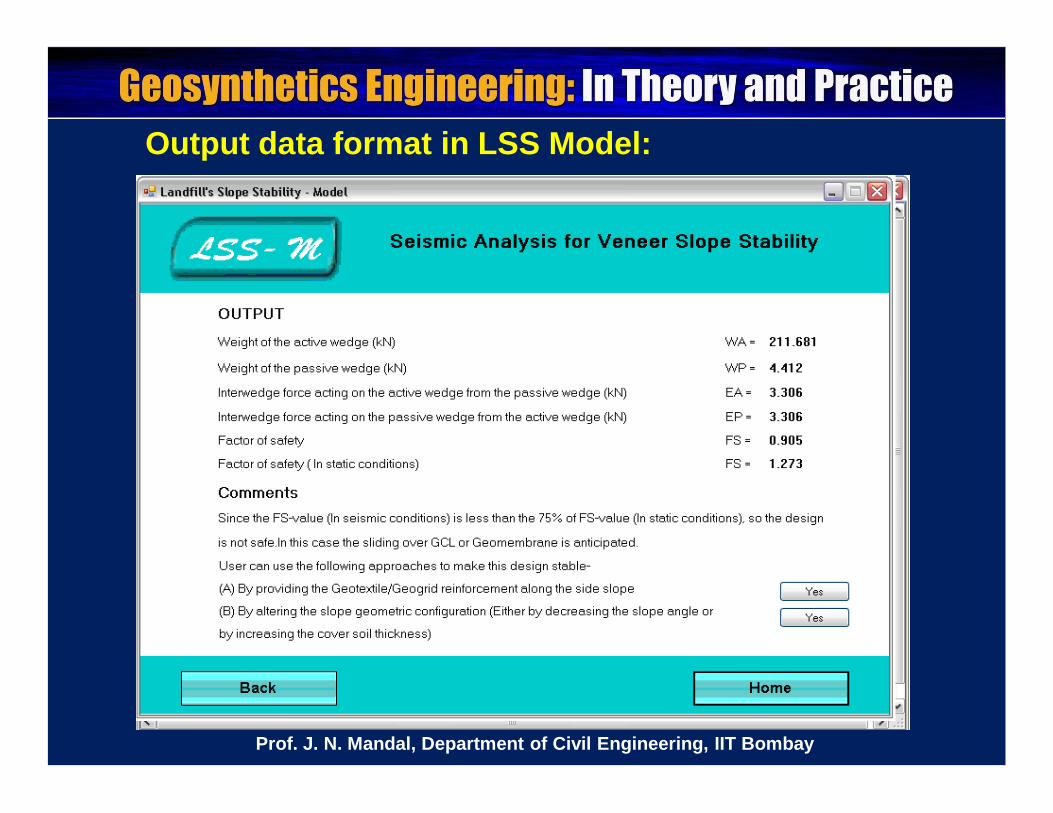
Output data format in LSS Model:
Prof. J. N. Mandal, Department of Civil Engineering, IIT Bombay
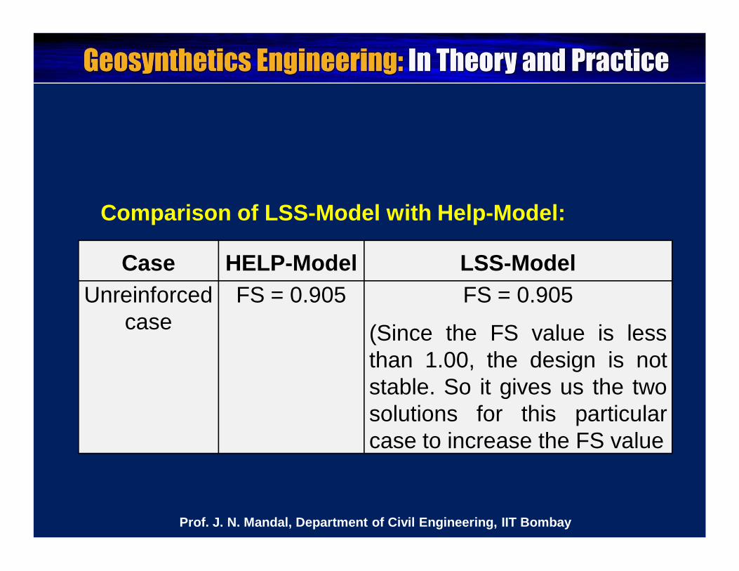
Case HELP-Model LSS-ModelUnreinforced
caseFS = 0.905 FS = 0.905
(Since the FS value is lessthan 1.00, the design is notstable. So it gives us the twosolutions for this particularcase to increase the FS value
Comparison of LSS-Model with Help-Model:
Prof. J. N. Mandal, Department of Civil Engineering, IIT Bombay

Please let us hear from you
Any question?
Prof. J. N. Mandal, Department of Civil Engineering, IIT Bombay
Prof. J. N. Mandal
Department of civil engineering, IIT Bombay, Powai , Mumbai 400076, India. Tel.022-25767328email: [email protected]
Prof. J. N. Mandal, Department of Civil Engineering, IIT Bombay