lamot corporation product selection guide · 2 lamot rupture discs lamot for quality since 1964,...
TRANSCRIPT

LAMOT® CORPORATIONProduct Selection Guide L-1000-1
2
LAMOT RUPTURE DISCSLAMOT FOR QUALITY
Since 1964, LAMOT Corporationhas manufactured rupture discs andrupture disc holders, using proventechniques, industry standards, andmodern manufacturing methods. Asa customer, we know you expectboth product quality anddependable service. When youchoose LAMOT, this is preciselywhat you receive. All manufacturingis performed under an approvedISO 9001 Quality AssuranceSystem to assure that rupture discsand holders are built to exactingspecifications. Our sales people areready to offer immediate assistancewhen you need an answer, have aproblem to solve, or an order toplace.
When you choose LAMOT, thereare three advantages you cancount on with every order:
• Quick delivery
• Competitive price
• Quality
Rupture disc holders aremanufactured using computercontrolled equipment, thus ensuringquality finishes and dimensionalaccuracy. Our rupture discs aremanufactured from a variety ofmetals which are purchasedaccording to closely controlledspecifications.
Special metal forming techniquesand state-of-the-art pressureindicators insure very accuraterecorded rupture pressures. This, incombination with our years ofmanufacturing experience anddedication to quality, is assuranceof precision performance fromLAMOT products.
LAMOT invites inquiries on rupturedisc applications requiring specialdesigns or variations of ourstandard holders. Our highlyexperienced staff is available forholder design and materialselection according to yourspecifications.
LAMOT Corporation produces tensiontype rupture discs for a wide range ofrupture disc holder configurations. Theserupture discs include both Standard andComposite designs.
What is a Standard TypeRupture Disc?
The Standard Rupture Disc is a solidmetal, prebulged (preformed) differentialpressure relief device. It is widely used intoday's industry to protect equipment,vessels, and systems from anoverpressure condition. The rupture discprovides instantaneous full-openingwithin milliseconds of an overpressuresituation. LAMOT Corporation'sStandard Rupture Disc providesperformance under pressure and is theguardian of the system.
* Teflon is a registered trademark of E.I. du Pont de Nemoursand Company used under license.
Top left cover photo courtesy of Air Liquide America; Houston, Texas.
The Standard Rupture Disc is usuallyused in systems that have an operatingpressure of up to 70% of the rupturedisc's rated burst pressure. Under idealoperating conditions, such as staticpressure with operating temperaturesthat are well below the maximumrecommended temperatures for therupture disc material being used, theStandard Rupture Disc may besubjected to operating pressures inexcess of 70% of the rated burstpressure. Consult your LAMOTrepresentative or the factory for detailedinformation about the use of theStandard Rupture Disc at operatingpressures greater than 70% of the ratedburst pressure. The minimum andmaximum burst pressures for theStandard Rupture Disc are found inTable IV.
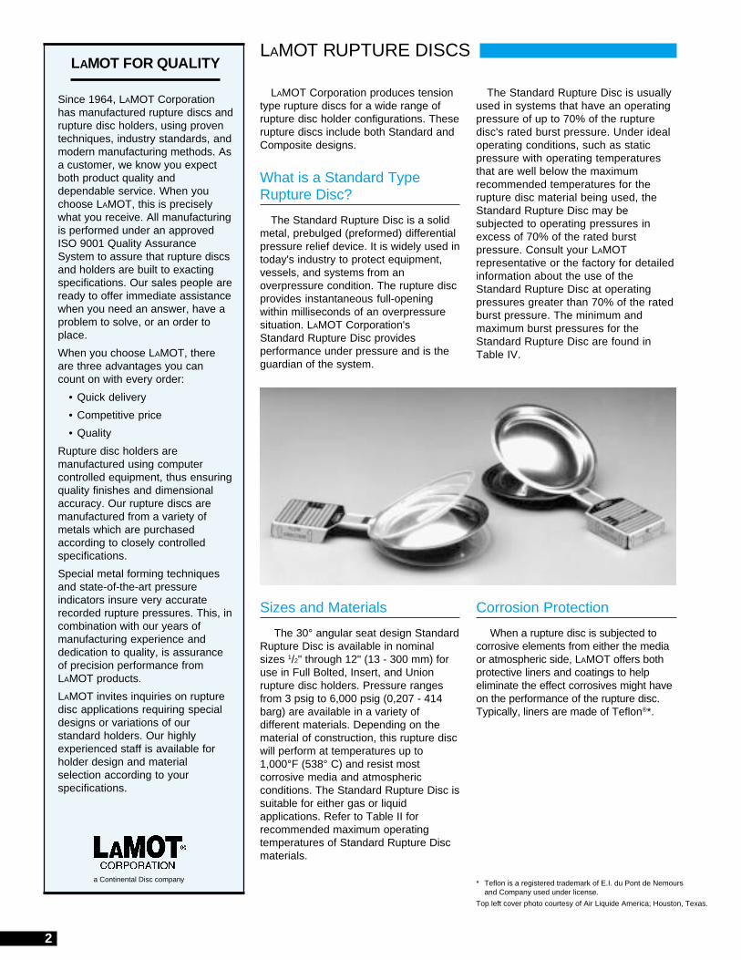
Sizes and Materials
The 30° angular seat design StandardRupture Disc is available in nominalsizes 1/2" through 12" (13 - 300 mm) foruse in Full Bolted, Insert, and Unionrupture disc holders. Pressure rangesfrom 3 psig to 6,000 psig (0,207 - 414barg) are available in a variety ofdifferent materials. Depending on thematerial of construction, this rupture discwill perform at temperatures up to1,000°F (538° C) and resist mostcorrosive media and atmosphericconditions. The Standard Rupture Disc issuitable for either gas or liquidapplications. Refer to Table II forrecommended maximum operatingtemperatures of Standard Rupture Discmaterials.
Corrosion Protection
When a rupture disc is subjected tocorrosive elements from either the mediaor atmospheric side, LAMOT offers bothprotective liners and coatings to helpeliminate the effect corrosives might haveon the performance of the rupture disc.Typically, liners are made of Teflon®*.
a Continental Disc company
3
LAMOT RUPTURE DISCS
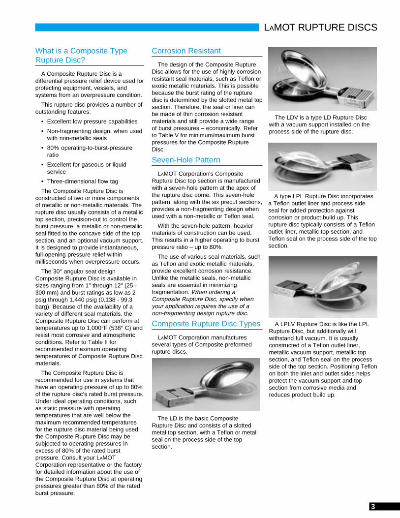
The LDV is a type LD Rupture Discwith a vacuum support installed on theprocess side of the rupture disc.
A type LPL Rupture Disc incorporatesa Teflon outlet liner and process sideseal for added protection againstcorrosion or product build up. Thisrupture disc typically consists of a Teflonoutlet liner, metallic top section, andTeflon seal on the process side of the topsection.
A LPLV Rupture Disc is like the LPLRupture Disc, but additionally willwithstand full vacuum. It is usuallyconstructed of a Teflon outlet liner,metallic vacuum support, metallic topsection, and Teflon seal on the processside of the top section. Positioning Teflonon both the inlet and outlet sides helpsprotect the vacuum support and topsection from corrosive media andreduces product build up.
The LD is the basic CompositeRupture Disc and consists of a slottedmetal top section, with a Teflon or metalseal on the process side of the topsection.
Corrosion Resistant
The design of the Composite RuptureDisc allows for the use of highly corrosionresistant seal materials, such as Teflon orexotic metallic materials. This is possiblebecause the burst rating of the rupturedisc is determined by the slotted metal topsection. Therefore, the seal or liner canbe made of thin corrosion resistantmaterials and still provide a wide rangeof burst pressures – economically. Referto Table V for minimum/maximum burstpressures for the Composite RuptureDisc.
Seven-Hole Pattern
LAMOT Corporation's CompositeRupture Disc top section is manufacturedwith a seven-hole pattern at the apex ofthe rupture disc dome. This seven-holepattern, along with the six precut sections,provides a non-fragmenting design whenused with a non-metallic or Teflon seal.
With the seven-hole pattern, heaviermaterials of construction can be used.This results in a higher operating to burstpressure ratio – up to 80%.
The use of various seal materials, suchas Teflon and exotic metallic materials,provide excellent corrosion resistance.Unlike the metallic seals, non-metallicseals are essential in minimizingfragmentation. When ordering aComposite Rupture Disc, specify whenyour application requires the use of anon-fragmenting design rupture disc.
Composite Rupture Disc Types
LAMOT Corporation manufacturesseveral types of Composite preformedrupture discs.
What is a Composite TypeRupture Disc?
A Composite Rupture Disc is adifferential pressure relief device used forprotecting equipment, vessels, andsystems from an overpressure condition.
This rupture disc provides a number ofoutstanding features:
• Excellent low pressure capabilities
• Non-fragmenting design, when usedwith non-metallic seals
• 80% operating-to-burst-pressureratio
• Excellent for gaseous or liquidservice
• Three-dimensional flow tag
The Composite Rupture Disc isconstructed of two or more componentsof metallic or non-metallic materials. Therupture disc usually consists of a metallictop section, precision-cut to control theburst pressure, a metallic or non-metallicseal fitted to the concave side of the topsection, and an optional vacuum support.It is designed to provide instantaneous,full-opening pressure relief withinmilliseconds when overpressure occurs.
The 30° angular seat designComposite Rupture Disc is available insizes ranging from 1" through 12" (25 -300 mm) and burst ratings as low as 2psig through 1,440 psig (0,138 - 99,3barg). Because of the availability of avariety of different seal materials, theComposite Rupture Disc can perform attemperatures up to 1,000°F (538° C) andresist most corrosive and atmosphericconditions. Refer to Table II forrecommended maximum operatingtemperatures of Composite Rupture Discmaterials.
The Composite Rupture Disc isrecommended for use in systems thathave an operating pressure of up to 80%of the rupture disc’s rated burst pressure.Under ideal operating conditions, suchas static pressure with operatingtemperatures that are well below themaximum recommended temperaturesfor the rupture disc material being used,the Composite Rupture Disc may besubjected to operating pressures inexcess of 80% of the rated burstpressure. Consult your LAMOTCorporation representative or the factoryfor detailed information about the use ofthe Composite Rupture Disc at operatingpressures greater than 80% of the ratedburst pressure.

4
Each rupture disc application has itsown unique operating conditions. Factorssuch as cycling and ratio of operatingpressure must be considered to obtainmaximum service life. The range ofmaterials available for Standard orComposite rupture discs, combined withoptional protective liners, vacuumsupports, and protective rings, provide awide selection of rupture discs for anyapplication.
Protective Rings — Protective ringsmay be used on rupture discs made ofthinner materials or in instances wheredelicate liners are used. These ringsprotect the rupture disc from foreignmaterial in the seating area. Protectiverings also enable easier handling ofrupture discs during installation.
Dent Protectors — For situationswhere the outlet (vent side) dome of therupture disc may require protection fromphysical environmental elements, anoptional dent protector can be suppliedto minimize damage.
STANDARD AND COMPOSITE RUPTURE DISCS
Options
Manufacturing Range
The manufacturing range is defined asthe allowable pressure range withinwhich a rupture disc is rated. It is basedupon the customer specified burstpressure. The manufacturing ranges forLAMOT Corporation’s Standard andComposite rupture discs are outlined inTable I.
Burst Tolerance
After the rupture disc has beenmanufactured and tested, it is markedwith the rated burst pressure. The rated(marked) burst pressure is establishedby bursting a minimum of two rupturediscs and averaging the pressures atwhich the rupture discs burst. Thisaverage is the rated (marked) burstpressure of the rupture disc.
Standard and Composite rupture discsare provided with a burst tolerance asoutlined in Table I, in accordance withthe ASME Code. Burst tolerance appliesonly to the rated (marked) burst pressureof the rupture disc.
1. Special reduced manufacturingranges are available uponrequest. Please consult yourLAMOT representative or thefactory for additional information.
2. Burst tolerances are themaximum expected variation fromthe rupture disc's rated (marked)burst pressure.
NOTES:
Vacuum Supports — Due to thethinness of some rupture disc materials,it is necessary to support a rupture discwhen a system vacuum occurs. LAMOTCorporation provides vacuum supportsfor rupture discs that will withstand a fullsystem vacuum, eliminating damage tothe rupture disc and ensuring properoperation. For backpressure conditionshigher than 14.7 psig (1,01 barg), consultyour LAMOT Corporation representativeor the factory. When ordering a Standardor Composite rupture disc that will besubjected to a vacuum condition, clearlyspecify the exact conditions that therupture disc will encounter. LAMOTCorporation will supply a vacuum supportwhen specified. Vacuum supports aremanufactured to mate with a specificrupture disc and are permanentlyattached to ensure proper installation.
Handling Supports — To aid in thehandling of rupture discs that are madeof thin materials and help preventdamage during installation, an optionalattached Handling Support can besupplied. This helps protect the productfrom damage that could affect the burstpressure setting of the rupture disc.
Gaskets — Gaskets may be used onthe process side of the rupture disc toenhance sealing where scratches or pitshave occurred in the seating area of theholder. A gasket lines the seating area ofthe rupture disc, improving sealingcapability, provided the holder has beenproperly cleaned according to productinstallation instructions.
Table I - Manufacturing Range / Burst Tolerance @ 72°FFor Standard and Composite Rupture Discs
Specified Manufacturing BurstBurst Pressure Range Tolerance
psig barg % Under % Over
2 - 5 0,138 - 0,345 -40 +40 ±25%
6 - 8 0,414 - 0,552 -40 +40 ±20%
9 - 12 0,621 - 0,815 -30 +30 ±15%
13 - 14 0,896 - 0,965 -10 +20 ±10%
15 - 19 1,03 - 1,31 -10 +20 ±2 psig (±0,138 barg)
20 - 39 1,38 - 2,69 - 4 +14 ±2 psig (±0,138 barg)
40 - 50 2,76 - 3,45 -4 +14 ±5%
51 - 100 3,52 - 6,90 -4 +10 ±5%
101 - 500 6,96 - 34,5 -4 +7 ±5%
501 - up 34,6 - UP -3 +6 ±5%
3. Coincident temperature testing isavailable upon request.
4. LAMOT Corporation canmanufacture Standard orComposite rupture discs to complywith ASME Code Stamprequirements.

5
Recommended MaximumTemperatures
Normally, the burst pressure of arupture disc will decrease as theoperating temperature increases.Table II states the maximum tempera-tures for commonly used rupture discmaterials, liners, and coatings.
Table II - Maximum Temperature For Rupture DiscMaterials, Liners, and Coatings
Seating Configurations
LAMOT's Standard Rupture Disc isavailable in a 30° angular "Light-Lip" seatfor normal operating pressures and a 30°angular "Heavy-Lip" seat for higherpressures. Size, burst pressure of therupture disc and flange class determinethe recommended seat design. Refer toTable III for information on application ofHeavy-Lip seating.
ASME Certification
LAMOT Corporation has beenaccredited and is authorized by theASME Code to utilize the CodeSymbol Stamp for product built inaccordance with the requirements of theASME Boiler and Pressure Vessel Code,Section VIII, Division 1.
The flow performance of LAMOTrupture discs was certified by TheNational Board of Boiler and PressureVessel Inspectors. These certified flowresistance (KR) and minimum net flowarea values are available from LAMOTCorporation or The National Board ofBoiler and Pressure Vessel Inspectors.
When specified, LAMOT rupture discswill be manufactured in accordance withASME Code Sections III or VIII, ISO,DIN, EN, BSI, JIS or other codes asrequired. For these applications, LAMOTwill manufacture, temperature test andmark the rupture discs to comply withspecific code requirements.
Table III - Recommended Usagefor Heavy-Lip Seating Design
White bar indicates 'psig'. Grey bar indicates 'barg'.
Rupture DiscNominal Flange Class Rating
Size ANSI DIN JIS (psig / barg)
1/2 in 1500 - UP 6,000 - UP
13mm 320 - UP - 414 - UP
1 in 1500 - UP 3,600 - UP
25mm 250 -UP - 248 - UP
1-1/2 in 900 - UP 2,160 - UP
40mm 160 - UP - 149 - UP
2 in 900 - UP 2,160 - UP
50mm 160 - UP - 149 - UP
3 in 1500 - UP 3,600 - UP
80mm 250 - UP - 248 - UP
4 in 1500 - UP 3,600 - UP
100mm 250 - UP - 248 - UP
NOTE: All other sizes and classes will beprovided with "Light-Lip" design.
STANDARD AND COMPOSITE RUPTURE DISCS
Three-DimensionalFlow Direction Tag
LAMOT's Three Dimensional FlowDirection Tag provides instant visualverification that the rupture disc has beencorrectly oriented into the system. The3-D tag extends beyond the holder toinsure clear visibility for easierinstallation and inspection after therupture disc has been installed.
Tags, as a standard, are attached toall Standard and Composite rupturediscs 1" (25 mm) nominal size andabove. Tags cannot be attached to arupture disc intended for use in a ScrewType or Throwaway Holder. Tags can beattached, on request, to rupture discs foruse in a Union Type Holder. Contact thefactory for more details.
* Inconel and Monel are registered trademarks of the Inco family of companies.
MaterialsTemperature Limit
°F °C
Aluminum 260 127
Nickel / Monel®* 800 427
316SS 900 482
Inconel®* 1,000 538
FEP Teflon Lining or Coating 400 204
TFE or PFA Lining 500 260

6
STANDARD AND COMPOSITE RUPTURE DISCS
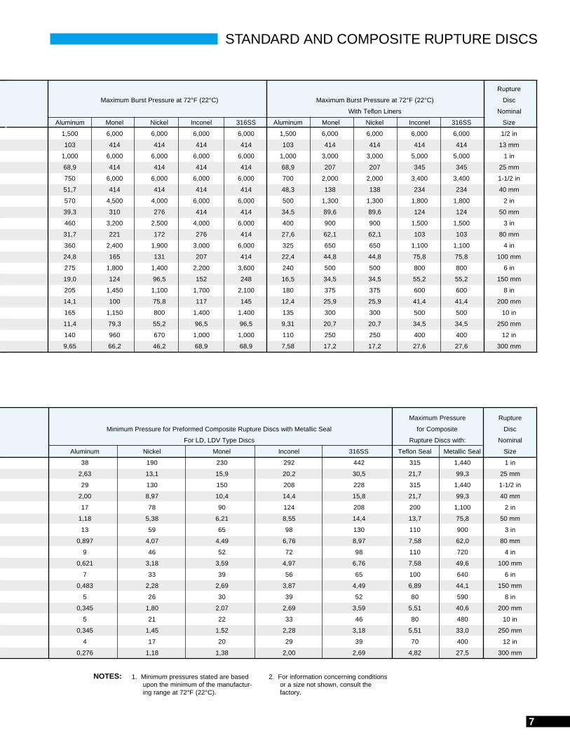
Table IV - Minimum/Maximum Burst Pressures for Standard Rupture Discs at 72°F (22°C)
Rupture Standard Rupture Disc Minimum Protective Ring: When Burst Pressure
Disc Minimum Burst Pressure at 72°F (22°C) Burst Pressure with Teflon Liner is less than value stated below,
Nominal (Add to Rupture Disc Minimum Burst Pressure) a Protective Ring is recommended
Size Aluminum Monel Nickel Inconel 316SS Inlet or Outlet Only Both Inlet & Outlet Aluminum Monel Nickel Inconel 316SS
1/2 in 65 350 300 560 760 150 300 520 3,000 2,290 3,600 3,700
13 mm 4,48 24,1 20,7 38,6 52,4 10,3 20,7 35,9 207 158 248 255
1 in 29 180 150 250 420 50 100 260 1,500 1,145 1,800 1,830
25 mm 2,00 12,4 10,3 17,2 29,0 3,45 6,90 18,0 103 78,9 124 126
1-1/2 in 22 116 100 150 275 35 70 180 1,030 790 1,240 1,255
40 mm 1,52 8,00 6,90 10,3 19,0 2,41 4,83 12,4 71,0 54,4 85,5 86,5
2 in 13 70 60 110 150 25 50 110 635 485 760 775
50 mm 0,896 4,83 4,14 7,58 10,3 1,72 3,45 7,58 43,8 33,4 52,4 53,4
3 in 10 50 45 80 117 15 30 75 445 340 535 545
80 mm 0,690 3,45 3,10 5,52 8,07 1,03 20,7 5,17 30,7 23,4 36,9 37,6
4 in 7 40 35 70 90 11 22 60 350 270 420 430
100 mm 0,483 2,76 2,41 4,83 6,21 0,759 1,52 4,14 24,1 18,6 29,0 29,6
6 in 5 30 25 47 62 8 16 45 260 200 315 320
150 mm 0,345 2,07 1,72 3,24 4,27 0,552 1,10 3,10 17,9 13,8 21,7 22,1
8 in 4 23 20 34 51 6 12 35 200 155 240 245
200 mm 0,276 1,59 1,38 2,34 3,52 0,414 0,827 2,41 13,8 10,7 16,5 16,9
10 in 4 17 16 30 43 5 10 28 160 125 195 200
250 mm 0,276 1,17 1,10 2,07 2,96 0,345 0,690 1,93 11,0 8,62 13,4 13,8
12 in 3 15 13 25 36 4 8 24 135 105 160 165
300 mm 0,207 1,03 0,900 2,14 2,48 0,276 0,552 1,65 9,31 7,24 11,0 11,4
Rupture
Disc Minimum Pressure for Preformed Composite Rupture Discs with Teflon Seal
Nominal LD LDV LPL LPLV
Size TFE FEP,PFA TFE FEP,PFA TFE FEP,PFA TFE FEP,PFA
1 in 25 30 30 35 35 40 60 80
25 mm 1,73 2,07 2,07 2,42 2,42 2,76 4,14 5,52
1-1/2 in 22 27 25 34 32 38 60 75
40 mm 1,52 1,87 1,73 2,35 2,21 2,63 4,14 5,18
2 in 7 15 10 18 15 20 28 35
50 mm 0,483 1,04 0,690 1,25 1,04 1,38 1,94 2,42
3 in 6 8 8 11 11 16 18 25
80 mm 0,414 0,552 0,552 0,759 0,759 1,11 1,25 1,73
4 in 5 7 7 8 6 9 15 18
100 mm 0,345 0,483 0,483 0,552 0,414 0,621 1,04 1,25
6 in 3 4 5 7 5 7 12 14
150 mm 0,207 0,276 0,345 0,483 0,345 0,483 0,828 0,966
8 in 2 3 5 5 4 5 11 11
200 mm 0,138 0,207 0,345 0,345 0,276 0,345 0,759 0,759
10 in - 3 - 5 - 5 - 8
250 mm - 0,207 - 0,345 - 0,345 - 0,552
12 in - 2 - 4 - 5 - 8
300 mm - 0,138 - 0,276 - 0,345 - 0,552
Table V - Minimum/Maximum Burst Pressures for Preformed Composite Rupture Discsat 72°F (22°C)White bars indicate 'psig'. Grey bars indicate 'barg'.
White bars indicate 'psig'. Grey bars indicate 'barg'.
7
Rupture
Maximum Burst Pressure at 72°F (22°C) Maximum Burst Pressure at 72°F (22°C) Disc
With Teflon Liners Nominal
Aluminum Monel Nickel Inconel 316SS Aluminum Monel Nickel Inconel 316SS Size
1,500 6,000 6,000 6,000 6,000 1,500 6,000 6,000 6,000 6,000 1/2 in
103 414 414 414 414 103 414 414 414 414 13 mm
1,000 6,000 6,000 6,000 6,000 1,000 3,000 3,000 5,000 5,000 1 in
68,9 414 414 414 414 68,9 207 207 345 345 25 mm
750 6,000 6,000 6,000 6,000 700 2,000 2,000 3,400 3,400 1-1/2 in
51,7 414 414 414 414 48,3 138 138 234 234 40 mm
570 4,500 4,000 6,000 6,000 500 1,300 1,300 1,800 1,800 2 in
39,3 310 276 414 414 34,5 89,6 89,6 124 124 50 mm
460 3,200 2,500 4,000 6,000 400 900 900 1,500 1,500 3 in
31,7 221 172 276 414 27,6 62,1 62,1 103 103 80 mm
360 2,400 1,900 3,000 6,000 325 650 650 1,100 1,100 4 in
24,8 165 131 207 414 22,4 44,8 44,8 75,8 75,8 100 mm
275 1,800 1,400 2,200 3,600 240 500 500 800 800 6 in
19,0 124 96,5 152 248 16,5 34,5 34,5 55,2 55,2 150 mm
205 1,450 1,100 1,700 2,100 180 375 375 600 600 8 in
14,1 100 75,8 117 145 12,4 25,9 25,9 41,4 41,4 200 mm
165 1,150 800 1,400 1,400 135 300 300 500 500 10 in
11,4 79,3 55,2 96,5 96,5 9,31 20,7 20,7 34,5 34,5 250 mm
140 960 670 1,000 1,000 110 250 250 400 400 12 in
9,65 66,2 46,2 68,9 68,9 7,58 17,2 17,2 27,6 27,6 300 mm
Maximum Pressure Rupture
Minimum Pressure for Preformed Composite Rupture Discs with Metallic Seal for Composite Disc
For LD, LDV Type Discs Rupture Discs with: Nominal
Aluminum Nickel Monel Inconel 316SS Teflon Seal Metallic Seal Size
38 190 230 292 442 315 1,440 1 in
2,63 13,1 15,9 20,2 30,5 21,7 99,3 25 mm
29 130 150 208 228 315 1,440 1-1/2 in
2,00 8,97 10,4 14,4 15,8 21,7 99,3 40 mm
17 78 90 124 208 200 1,100 2 in
1,18 5,38 6,21 8,55 14,4 13,7 75,8 50 mm
13 59 65 98 130 110 900 3 in
0,897 4,07 4,49 6,76 8,97 7,58 62,0 80 mm
9 46 52 72 98 110 720 4 in
0,621 3,18 3,59 4,97 6,76 7,58 49,6 100 mm
7 33 39 56 65 100 640 6 in
0,483 2,28 2,69 3,87 4,49 6,89 44,1 150 mm
5 26 30 39 52 80 590 8 in
0,345 1,80 2,07 2,69 3,59 5,51 40,6 200 mm
5 21 22 33 46 80 480 10 in
0,345 1,45 1,52 2,28 3,18 5,51 33,0 250 mm
4 17 20 29 39 70 400 12 in
0,276 1,18 1,38 2,00 2,69 4,82 27,5 300 mm
1. Minimum pressures stated are basedupon the minimum of the manufactur-ing range at 72°F (22°C).
2. For information concerning conditionsor a size not shown, consult thefactory.
NOTES:
STANDARD AND COMPOSITE RUPTURE DISCS
8
RUPTURE DISC HOLDERS
Insert Holders
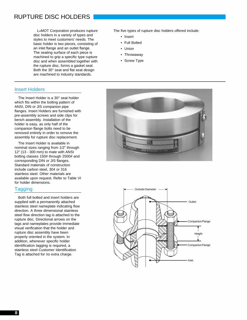
The Insert Holder is a 30° seat holderwhich fits within the bolting pattern ofANSI, DIN or JIS companion pipeflanges. Insert Holders are furnished withpre-assembly screws and side clips forbench assembly. Installation of theholder is easy, as only half of thecompanion flange bolts need to beremoved entirely in order to remove theassembly for rupture disc replacement.
The Insert Holder is available innominal sizes ranging from 1/2" through12" (13 - 300 mm) to mate with ANSIbolting classes 150# through 2500# andcorresponding DIN or JIS flanges.Standard materials of constructioninclude carbon steel, 304 or 316stainless steel. Other materials areavailable upon request. Refer to Table VIfor holder dimensions.
Tagging
Both full bolted and insert holders aresupplied with a permanently attachedstainless steel nameplate indicating flowdirection. A three dimensional stainlesssteel flow direction tag is attached to therupture disc. Directional arrows on thetags and nameplates provide immediatevisual verification that the holder andrupture disc assembly have beenproperly oriented in the system. Inaddition, whenever specific holderidentification tagging is required, astainless steel Customer IdentificationTag is attached for no extra charge.
LAMOT Corporation produces rupturedisc holders in a variety of types andstyles to meet customers' needs. Thebasic holder is two pieces, consisting ofan inlet flange and an outlet flange.The seating surface of each piece ismachined to grip a specific type rupturedisc and when assembled together withthe rupture disc, forms a gasket seal.Both the 30° seat and flat seat designare machined to industry standards.
The five types of rupture disc holders offered include:
• Insert
• Full Bolted
• Union
• Throwaway
• Screw Type
Outside Diameter
Outlet
Companion Flange
Inlet
Height
Companion Flange

9NOTE: Consult factory for availability of flange classes or sizes not listed.
Table VI - 30° Insert Holder Weights and DimensionsANSI DIN JIS Height Weight
Nominal Class Outside Dia. Class Outside Dia. Class Outside Dia. (in / mm) (lbs / kg)Size (in / mm) (mm) (mm)
150 1.75 / 44,5 1.67 / 42 1.0 / 0,451/2" 300 / 600 2.00 / 50,8 1.67 / 42 1.4 / 0,64
13 mm 900 / 1500 2.38 / 60,3 1.86 / 47 2.3 / 1,0150 2.50 / 63,5 1.67 / 42 1.9 / 0,90
300 / 600 2.75 / 69,9 10 / 40 69,9 10 / 20 69,9 1.67 / 42 2.5 / 1,11" 30 / 40 76,0 1.67 / 42 2.9 / 1,3
25 mm 64 / 160 82,0 2.38 / 60 4.9 / 2,2250 82,0 2.38 / 60 4.9 / 2,2
900 / 1500 3.00 / 76,2 2.38 / 60 4.1 / 1,9150 3.25 / 82,6 1.67 / 42 3.0 / 1,4
10 / 20 86,0 1.67 / 42 3.4 / 1,5300 / 600 3.63 / 92,2 10 / 40 92,2 1.67 / 42 4.0 / 1,8
1-1/2" 900 / 1500 3.75 / 95,3 2.66 / 68 6.9 / 2,740 mm 30 / 40 97,0 1.67 / 42 4.5 / 2,0
64 / 160 102,0 2.66 / 68 8.1 / 3,7250 108,0 2.66 / 68 10 / 4,5
150 4.00 / 101,6 10 101,6 1.67 / 42 3.6 / 1,616 / 20 101,6 1.67 / 42 3.6 / 1,6
300 / 600 4.25 / 108,0 10 / 40 108,0 1.67 / 42 4.3 / 2,02" 64 111,0 30 / 40 111,0 1.67 / 42 4.8 / 2,2
50 mm 100 / 160 118,0 3.15 / 80 11 / 5,0250 123,0 3.15 / 80 13 / 5,9
900 / 1500 5.50 / 139,7 3.15 / 80 17 / 7,810 131,0 1.67 / 42 5.2 / 2,4
150 5.25 / 133,4 1.67 / 42 5.5 / 2,516 / 20 137,0 1.67 / 42 6.1 / 2,8
10 142,0 2.13 / 54 8.9 / 4,03" 16 / 40 142,0 2.13 / 54 8.9 / 4,0
80 mm 300 / 600 5.75 / 146,1 64 146,1 30 / 40 146,1 2.13 / 54 10 / 4,5100 / 160 153,0 3.21 / 82 19 / 8,6
900 6.50 / 165,1 3.21 / 82 23 / 10250 170,0 3.71 / 94 29 / 13
1500 6.75 / 171,5 3.71 / 94 29 / 1310 156,0 1.67 / 42 6.0 / 2,7
10 / 16 162,0 16 / 20 162,0 1.67 / 42 7.4 / 3,425 / 40 168,0 30 168,0 2.15 / 55 12 / 5,4
150 6.75 / 171,5 1.67 / 42 9.1 / 4,164 173,0 3.13 / 79 18 / 8,3
4" 300 7.00 / 177,8 2.15 / 55 13 / 5,9100 mm 40 180,0 2.15 / 55 14 / 6,4
100 / 160 180,0 3.63 / 92 26 / 12600 7.50 / 190,5 3.13 / 79 25 / 11
250 202,0 4.35 / 111 45 / 20900 8.00 / 203,2 3.63 / 92 37 / 171500 8.13 / 206,5 4.35 / 111 47 / 22
10 / 16 217,0 10 217,0 2.06 / 52 16 / 7,2150 8.63 / 219,2 2.06 / 52 17 / 7,7
25 / 40 223,0 2.93 / 74 26 / 1216 / 20 235,0 2.06 / 52 22 / 9,7
6" 64 247,0 3.96 / 101 55 / 25150 mm 300 9.75 / 247,7 30 247,7 2.93 / 74 37 / 17
100 / 160 257,0 4.53 / 115 71 / 3240 262,0 2.93 / 74 44 / 20
600 10.38 / 263,7 3.96 / 101 66 / 30900 11.25 / 285,8 4.53 / 115 95 / 43
10 267,0 2.31 / 58 25 / 1110 / 16 272,0 2.31 / 58 27 / 12
150 10.88 / 276,4 2.31 / 58 29 / 1316 / 20 280,0 2.31 / 58 31 / 14
8" 25 283,0 3.30 / 84 44 / 20200 mm 40 290,0 3.30 / 84 48 / 22
30 293,0 3.30 / 84 50 / 23300 12.00 / 304,8 3.30 / 84 58 / 26
64 309,0 4.50 / 114 83 / 3840 312,0 3.30 / 84 63 / 29
600 12.50 / 317,5 4.50 / 114 91 / 4110 / 16 327,0 2.55 / 65 34 / 15
10 330,0 2.55 / 65 36 / 16150 13.25 / 336,6 2.55 / 65 40 / 18
25 340,0 4.18 / 106 69 / 3110" 40 352,0 4.18 / 106 81 / 37
250 mm 16 / 20 353,0 2.55 / 65 49 / 2230 357,0 4.18 / 106 86 / 39
300 14.13 / 358,9 4.18 / 106 88 / 4064 364,0 5.00 / 127 128 / 58
40 377,0 4.18 / 106 107 / 49100 391,0 5.00 / 127 163 / 74
600 15.63 / 397,0 5.00 / 127 171 / 785 367,0 2.55 / 65 36 / 1610 375,0 2.55 / 65 41 / 19
10 377,0 2.55 / 65 42 / 1916 383,0 2.55 / 65 46 / 21
12" 25 400,0 4.13 / 105 94 / 43300 mm 16 / 20 403,0 2.55 / 65 60 / 27
150 16.00 / 406,4 2.55 / 65 62 / 2840 417,0 30 417,0 4.13 / 105 114 / 52
300 16.50 / 419,1 4.13 / 105 116 / 5364 424,0 5.43 / 138 161 / 73
40 431,0 4.13 / 105 130 / 59600 17.88 / 454,2 5.43 / 138 211 / 96
INSERT RUPTURE DISC HOLDERS

10
FULL BOLTED RUPTURE DISC HOLDERS
Full Bolted Holders
LAMOT Corporation offers nineconnection combinations of full boltedholders compatible with ANSI, DIN or JISbolting classes. Full bolted holders areavailable in any combination of welded,threaded, or flat faced inlet and outletconnections. These holders are designedto be used with either Standard orComposite 30° seat rupture discs. The full bolted holder is available in
nominal sizes ranging from 1/2" through12" to mate with ANSI bolting classes150# through 2500#. Standard materialsof construction include carbon steel, 304or 316 stainless steel. Other materialsare available upon request. Refer toTables VII and VIII for dimensions andconnection combinations.
Table VIII - Full Bolted Holder Assembly Dimensions(All dimensions in inches. See drawing above.)
Studs Height Dimension Of Full Bolted Assembly Number
Nominal ANSI Outside Bolt
Size Class Diameter Circle No. Diameter #1 #2 #3 #4 #5 #6 #7 #8 #9
150 3.50 2.38 4 .50 2.20 2.38 3.13 2.81 3.00 3.75 1.75 1.88 2.63
1/2 in300 3.75 2.63 4 .50 2.00 2.63 3.50 2.88 3.50 4.38 1.69 1.75 2.63
600 3.75 2.63 4 .50 2.00 2.63 3.50 2.88 3.50 4.38 1.69 1.75 2.63
900/1500 4.75 3.25 4 .75 5.56 3.38 4.06 3.38 4.19 4.88 1.88 2.69 3.38
150 4.25 3.13 4 .50 1.94 2.78 3.56 2.75 3.59 4.38 1.13 1.97 2.75
1 in300 4.88 3.50 4 .63 2.25 2.97 4.00 3.13 3.84 4.88 1.38 2.09 3.13
600 4.88 3.50 4 .63 2.38 3.10 4.13 3.25 3.97 5.00 1.50 2.22 3.25
900/1500 5.88 4.00 4 .88 3.00 3.59 4.75 4.13 4.72 5.88 2.38 2.97 4.13
150 5.00 3.88 4 .50 2.25 3.03 4.00 3.13 3.91 4.88 1.38 2.16 3.13
300 6.13 4.50 4 .75 2.13 2.84 4.00 3.50 4.22 5.38 1.63 2.34 3.50
1-1/2 in 600 6.13 4.50 4 .75 2.38 3.09 4.25 3.75 4.47 5.63 1.88 2.59 3.75
900/1500 7.00 4.88 4 1.00 3.13 3.66 5.13 4.63 5.66 7.13 2.50 3.00 4.50
150 6.00 4.75 4 .63 2.13 2.97 3.88 3.25 4.10 5.00 1.50 2.35 3.25
300 6.50 5.00 8 .63 2.44 3.16 4.31 3.63 4.35 5.50 1.75 2.47 3.63
2 in 600 6.50 5.00 8 .63 2.81 3.53 4.69 4.00 4.72 5.88 2.13 2.84 4.00
900/1500 8.50 6.50 8 .88 3.88 4.63 6.38 5.63 6.38 8.13 3.13 3.88 5.63
150 7.50 6.00 4 .63 2.56 3.09 4.44 3.75 4.28 5.63 1.88 2.41 3.75
3 in300 8.25 6.63 8 .75 2.94 3.59 4.94 4.25 4.91 6.25 2.25 2.91 4.25
600 8.25 6.63 8 .75 3.19 3.85 5.19 4.63 5.28 6.63 2.63 3.28 4.63
900 9.50 7.50 8 .88 4.00 4.50 6.25 5.75 6.38 8.13 3.00 3.50 5.50
150 9.00 7.50 8 .63 2.75 3.72 4.88 4.00 4.97 6.13 1.88 2.84 4.00
4 in300 10.00 7.88 8 .75 3.56 4.34 5.69 4.69 5.47 6.81 2.50 3.28 4.63
600 10.75 8.50 8 .88 3.88 4.50 5.97 5.63 6.38 7.72 3.13 3.75 5.22
900 11.50 9.25 8 1.13 5.00 5.38 7.38 6.50 7.13 9.13 3.50 4.50 6.25
150 11.00 9.50 8 .75 3.25 4.09 5.56 4.75 5.59 7.06 2.19 3.03 4.50
6 in 300 12.50 10.63 12 .75 3.50 4.13 6.50 5.31 5.94 7.88 2.88 3.50 5.06
600 14.00 11.50 12 1.00 4.75 6.13 7.38 6.75 8.25 9.38 3.63 5.63 4.75
8 in150 13.50 11.75 8 .75 4.00 5.25 6.88 5.19 6.44 8.06 2.25 3.50 5.13
300 15.00 13.00 12 .88 4.25 5.38 7.00 6.25 7.25 8.88 3.25 4.75 6.00
10 in 150 16.00 14.25 12 .88 — — — 5.25 6.63 8.13 2.38 — 5.25
12 in 150 19.00 17.00 12 .88 2.63 — 4.75 5.75 7.38 7.94 2.50 — 5.69
Table VII -Full Bolted HolderAssembly Numberand Connections
Assembly Connections
Number Inlet Outlet
1 Threaded Flat Face
2 Threaded Threaded
3 Threaded Weldneck
4 Weldneck Flat Face
5 Weldneck Threaded
6 Weldneck Weldneck
7 Flat Face Flat Face
8 Flat Face Threaded
9 Flat Face Weldneck
Bolt Circle
Height Dimension byAssembly Number
Outside Diameter

11
UNION TYPE RUPTURE DISC HOLDERS
Union TypeRupture Disc Holders
The Union Type Holder is designed toprovide flexibility of use in tight pipingconfigurations. These precisely builtholders combine remarkable ease ofinstallation with high pressure ratings inpipe sizes of 2 inches (50 mm) or less.Standard sizes, ratings and bores areshown in Table IX. Contact the factoryfor applications outside this range.
Specifications
These holders are designed forStandard or Composite type rupturediscs. Any combination of welded orthreaded connections is available. Allparts are available in Carbon Steel and316 Stainless Steel. The units aredesigned with 30° angular seating. Astainless steel tag is welded to theassembly for easy identification of size,pressure rating, and flow direction. Referto Tables IV and V for rupture discdetails.
If the unit has a threaded outlet, it canbe supplied with a muffled plug. Thisreduces reaction forces upon discrupture, and redirects fragments orproduct from dispersing directly from thenozzle. For more information on themuffled plug, contact the factory.
Product Identification
As a standard, rupture discs for use inUnion Type Holders are shipped with adetached tag, which should be affixed tothe completed assembly when therupture disc is installed. Under certaincircumstances, the ASME Code willallow such an installation.
For those requiring ASME complianceor simple, positive identification ofrupture disc installations, LAMOT offers aspecial Union Type Holder which allowsthe installation of a rupture disc with apermanently attached 3-dimensional flowdirection tag. The 3-D flow tag extendsbeyond the holder for easier verificationof orientation after the rupture disc hasbeen installed.
When ordering rupture discs, pleasestate whether the disc is to be installedin a Union Type Holder, and whether yourequire the standard configuration or apermanently attached 3-D flow tag.
#2U HolderThreaded Inlet - Threaded Outlet
#6U HolderWelded Inlet - Welded Outlet
Also Available:#3U Holder
Threaded Inlet - Welded Outlet#5U Holder
Welded Inlet - Threaded Outlet
3000# Assembly 4000# Assembly 6000# Assembly
Temp. Carbon Steel* 316SS** Carbon Steel* 316SS** Carbon Steel* 316SS**°F °C psig barg psig barg psig barg psig barg psig barg psig barg
100 37,8 3000 206 3000 206 4000 275 4000 275 6000 413 6000 413 200 93,3 2735 188 2580 177 3647 251 3440 237 5470 377 5160 355
300 149 2660 183 2330 160 3546 244 3107 214 5319 366 4660 321400 204 2567 177 2140 147 3423 236 2853 196 5135 354 4280 295500 260 — — 1990 137 — — 2653 182 — — 3980 274600 316 — — 1880 129 — — 2507 172 — — 3760 259700 371 — — 1810 124 — — 2413 166 — — 3620 249800 427 — — 1760 121 — — 2347 161 — — 3520 242900 482 — — 1730 119 — — 2307 159 — — 3460 2381000 538 — — 1458 100 — — 1943 134 — — 2915 201
Table X - Maximum Pressure Ratings for Union Holder
* Carbon Steel ratings are for Group 1.1 from ANSI B16.5** 316 SS ratings are for Group 2.2 from ANSI B16.5
Table IX - Union Holder SpecificationsOverall Height
Size Rating Bore Hex Size #2U #3U #5U #6U1/2 in
3000# Schedule 801.75" 2.75" 2.50" 2.55" 2.30"
13 mm 44,5 mm 69,9 mm 63,5 mm 64,8 mm 58,4 mm1/2 in
6000# Schedule 1602.00" 2.81" 2.94" 2.81" 2.94"
13 mm 50,8 mm 71,4 mm 74,7 mm 71,4 mm 74,7 mm1 in
2000# Schedule 802.50" 3.24" 2.93" 2.93" 2.63"
25 mm 63,5 mm 82,3 mm 74,4 mm 74,4 mm 66,8 mm1 in
4000# Schedule 803.00" 3.50" 3.03" 3.15" 2.63"
25 mm 76,2 mm 88,9 mm 77,0 mm 80,0 mm 66,8 mm1 in
6000# Schedule 1603.00" 3.50" 3.03" 3.15" 2.63"
25 mm 76,2 mm 88,9 mm 77,0 mm 80,0 mm 66,8 mm1-1/2 in
2000# Schedule 803.50" 3.75" 3.47" 3.72" 3.50"
40 mm 88,9 mm 95,3 mm 88,1 mm 94,5 mm 88,9 mm1-1/2 in
4000# Schedule 803.50" 3.75" 3.47" 3.72" 3.50"
40 mm 88,9 mm 95,3 mm 88,1 mm 94,5 mm 88,9 mm2 in
2000# Schedule 804.25" 3.85" 4.23" 4.35" 4.73"
50 mm 108 mm 97,8 mm 107 mm 110 mm 120 mm2 in
4000# Schedule 1605.00" 5.13" 4.85" 5.10" 5.13"
50 mm 127 mm 130 mm 123 mm 129 mm 130 mm
Note: A Union Type Holder with extra heavy wing nut lugs is available. Contact the factory for more information.

12
SCREW TYPE & THROWAWAY HOLDER ASSEMBLIES
Screw Type Assembly
Throwaway Assembly
Throwaway Holder Assembly
The Throwaway Assembly is a sealed,disposable unit for use in systems wherepressures do not exceed 3,000 psig (207barg). The assembly features a rupturedisc sealed between brass fittings. Afterrelieving an overpressure condition,changeout is easily performed byreplacing the entire assembly. TheThrowaway Assembly can be suppliedwith a Standard or Composite rupturedisc to accommodate various applicationrequirements.
Throwaway units are used on gasbottles, air conditioning systems, refrig-eration units, hydraulic accumulators,gas cylinders, portable compressed airsystems and laboratory equipment. TheThrowaway unit is a sealed unit.
Two units are available:
• A 1,000 psig (68,9 barg) design iscompatible with either a Standard orComposite rupture disc, up to amaximum 1,000 psig burst pressure
• For higher pressures, a 3,000 psig(207 barg) unit is available. It iscompatible with a Standard RuptureDisc.
The LAMOT Throwaway unit, with a1/2" or 3/4" Standard or 11/16"Composite flat seat rupture disc, consistsof three brass components:
• inlet• holddown ring• outlet
The inlet is available in 1/4", 3/8", 1/2",or 3/4" male pipe threads (MPT). Theoutlet component is available in variousconfigurations to match the requirementof your application (see Table XIII).
After the rupture disc is installed in theThrowaway Holder, the inlet and outletcomponents are permanently affixed toprovide a sealed assembly. Eachassembly is then inspected by a BetaBackscanner device to verify complianceto the proper rupture disc materialthickness. When an overpressurecondition occurs, the entire assemblycan be quickly removed and replacedwith a new assembly.
The maximum temperature limits ofthe Throwaway Holder are dependentupon the limitations of either the rupturedisc or the holder. In the case of themaximum allowable temperature, use thelesser limit of the two.
Throwaway HolderSpecifications
Maximum 1,000 psig or 3,000 psigPressure: (68,9 barg) (207 barg)
Maximum Temp.: 400°F(204°C)
Materials: All brass components
Screw Type Holder Assembly
LAMOT's Screw Type Assembly is areusable unit for use in systems withpressures up to 20,000 psig (1,379barg). A Standard or Composite rupturedisc is supplied separately from theScrew Type Holder. After anoverpressure condition occurs,changeout is accomplished bydisassembling the Screw Type Holderand replacing only the burst rupture disc.
The LAMOT Screw Type Assemblyis a flat seat design reusable holderwith 1/2" Standard, 11/16" Standard or11/16" Composite flat seat rupture disc.This assembly is used primarily forlaboratory applications and other smallpressure vessels or systems.
The Screw Type Holder, used witha Standard or Composite rupture disc,consists of three components:
• inlet• holddown ring• outlet
The inlet is available in 1/4", 3/8", and1/2" male pipe threads (MPT). The outletis available in 1/2" MPT, muffled or freeconfigurations.
The Screw Type Holder is availablewith the inlet, outlet, and holddown ringmade from brass or 316 Stainless Steel.Specify the required material whenordering. Other materials will be quotedon request.
The Screw Type Holder is reusable.After a rupture disc has burst, it may bereplaced by disassembling the outletfrom the inlet.
The 11/16" rupture disc with itsmatching holddown ring uses the sameinlet and outlet holder as the 1/2" rupturedisc with matching holddown ring. Referto Table XII for Screw Type Holderspecifications and dimensions.
Screw Type HolderSpecifications
Maximum Pressure: 20,000 psig(1,379 barg)
Maximum Temp.: 1,000°F(538°C)
Materials: All 316 Stainless Steelcomponents
Note: A brass unit is available with a maximumpressure of 1,000 psig (68,9 barg) and a maximumtemperature of 400°F (204°C).
13
SCREW TYPE & THROWAWAY HOLDER ASSEMBLIES
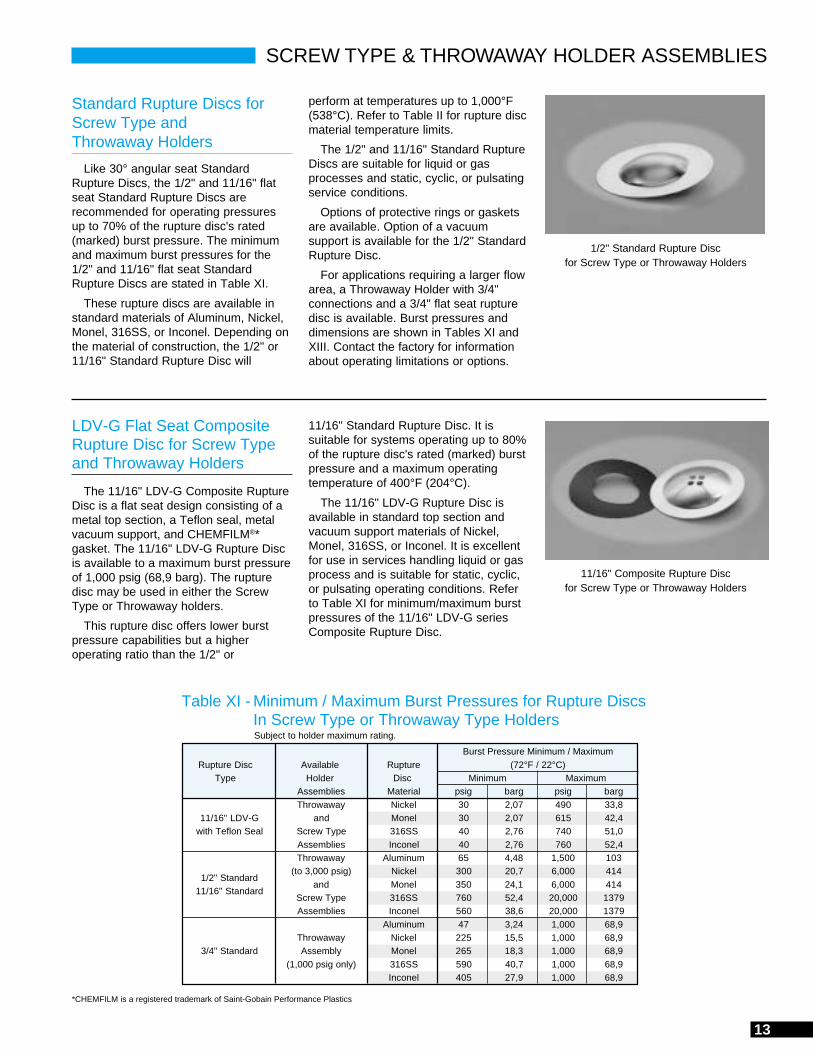
Standard Rupture Discs forScrew Type andThrowaway Holders
Like 30° angular seat StandardRupture Discs, the 1/2" and 11/16" flatseat Standard Rupture Discs arerecommended for operating pressuresup to 70% of the rupture disc's rated(marked) burst pressure. The minimumand maximum burst pressures for the1/2" and 11/16" flat seat StandardRupture Discs are stated in Table XI.
These rupture discs are available instandard materials of Aluminum, Nickel,Monel, 316SS, or Inconel. Depending onthe material of construction, the 1/2" or11/16" Standard Rupture Disc will
LDV-G Flat Seat CompositeRupture Disc for Screw Typeand Throwaway Holders
The 11/16" LDV-G Composite RuptureDisc is a flat seat design consisting of ametal top section, a Teflon seal, metalvacuum support, and CHEMFILM®*gasket. The 11/16" LDV-G Rupture Discis available to a maximum burst pressureof 1,000 psig (68,9 barg). The rupturedisc may be used in either the ScrewType or Throwaway holders.
This rupture disc offers lower burstpressure capabilities but a higheroperating ratio than the 1/2" or
Table XI - Minimum / Maximum Burst Pressures for Rupture DiscsIn Screw Type or Throwaway Type Holders
Burst Pressure Minimum / MaximumRupture Disc Available Rupture (72°F / 22°C)
Type Holder Disc Minimum MaximumAssemblies Material psig barg psig bargThrowaway Nickel 30 2,07 490 33,8
11/16" LDV-G and Monel 30 2,07 615 42,4with Teflon Seal Screw Type 316SS 40 2,76 740 51,0
Assemblies Inconel 40 2,76 760 52,4Throwaway Aluminum 65 4,48 1,500 103
1/2" Standard(to 3,000 psig) Nickel 300 20,7 6,000 414
11/16" Standardand Monel 350 24,1 6,000 414
Screw Type 316SS 760 52,4 20,000 1379Assemblies Inconel 560 38,6 20,000 1379
Aluminum 47 3,24 1,000 68,9Throwaway Nickel 225 15,5 1,000 68,9
3/4" Standard Assembly Monel 265 18,3 1,000 68,9(1,000 psig only) 316SS 590 40,7 1,000 68,9
Inconel 405 27,9 1,000 68,9
Subject to holder maximum rating.
perform at temperatures up to 1,000°F(538°C). Refer to Table II for rupture discmaterial temperature limits.
The 1/2" and 11/16" Standard RuptureDiscs are suitable for liquid or gasprocesses and static, cyclic, or pulsatingservice conditions.
Options of protective rings or gasketsare available. Option of a vacuumsupport is available for the 1/2" StandardRupture Disc.
For applications requiring a larger flowarea, a Throwaway Holder with 3/4"connections and a 3/4" flat seat rupturedisc is available. Burst pressures anddimensions are shown in Tables XI andXIII. Contact the factory for informationabout operating limitations or options.
11/16" Standard Rupture Disc. It issuitable for systems operating up to 80%of the rupture disc's rated (marked) burstpressure and a maximum operatingtemperature of 400°F (204°C).
The 11/16" LDV-G Rupture Disc isavailable in standard top section andvacuum support materials of Nickel,Monel, 316SS, or Inconel. It is excellentfor use in services handling liquid or gasprocess and is suitable for static, cyclic,or pulsating operating conditions. Referto Table XI for minimum/maximum burstpressures of the 11/16" LDV-G seriesComposite Rupture Disc.
1/2" Standard Rupture Discfor Screw Type or Throwaway Holders
11/16" Composite Rupture Discfor Screw Type or Throwaway Holders
*CHEMFILM is a registered trademark of Saint-Gobain Performance Plastics

14
SCREW TYPE HOLDER ASSEMBLY
Table XII - Screw Type Holder Specifications and Dimensions
Holder Maximum Holder Connection Assembly NumberDimensions Rotating
Rupture Height Across Hex Flats DiameterPressure @ Disc (A) Inlet Outlet Dimension72°F / 22°C Temp. Inlet Outlet Brass 316SS Size inch/mm (B) (C) (D)
1/4 MPT Muffled BLS1-25-M — 11/16" 2.28 / 57,93/8 MPT Muffled BLS1-37-M — 11/16" 2.28 / 57,91/2 MPT Muffled BLS1-50-M — 11/16" 2.28 / 57,9
1,000 psig 400°F 1/4 MPT 1/2 MPT BLS1-25-P — 11/16" 2.81 / 71,4 1-1/4 in 1-1/8 in 1.44 in
68,9 barg 204°C 3/8 MPT 1/2 MPT BLS1-37-P — 11/16" 2.81 / 71,4 31,8 mm 28,6 mm 36,6 mm1/2 MPT 1/2 MPT BLS1-50-P — 11/16" 2.81 / 71,41/4 MPT Free BLS1-25-F — 11/16" 2.03 / 51,63/8 MPT Free BLS1-37-F — 11/16" 2.19 / 55,61/2 MPT Free BLS1-50-F — 11/16" 2.03 / 51,61/4 MPT Muffled — 16LS3-25-M 11/16" 2.28 / 57,93/8 MPT Muffled — 16LS3-37-M 11/16" 2.28 / 57,91/2 MPT Muffled — 16LS3-50-M 11/16" 2.28 / 57,9
3,000 psig 1,000°F 1/4 MPT 1/2 MPT — 16LS3-25-P 11/16" 2.81 / 71,4 1-1/4 in 1-1/8 in 1.44 in
207 barg 538°C 3/8 MPT 1/2 MPT — 16LS3-37-P 11/16" 2.81 / 71,4 31,8 mm 28,6 mm 36,6 mm1/2 MPT 1/2 MPT — 16LS3-50-P 11/16" 2.81 / 71,41/4 MPT Free — 16LS3-25-F 11/16" 2.03 / 51,63/8 MPT Free — 16LS3-37-F 11/16" 2.03 / 51,61/2 MPT Free — 16LS3-50-F 11/16" 2.03 / 51,61/4 MPT Muffled — 16LS10-25-M 1/2" 2.28 / 57,93/8 MPT Muffled — 16LS10-37-M 1/2" 2.28 / 57,91/2 MPT Muffled — 16LS10-50-M 1/2" 2.28 / 57,9
10,000 psig 1,000°F 1/4 MPT 1/2 MPT — 16LS10-25-P 1/2" 2.81 / 71,4 1-1/4 in 1-1/8 in 1.44 in
689 barg 538°C 3/8 MPT 1/2 MPT — 16LS10-37-P 1/2" 2.81 / 71,4 31,8 mm 28,6 mm 36,6 mm1/2 MPT 1/2 MPT — 16LS10-50-P 1/2" 2.81 / 71,41/4 MPT Free — 16LS10-25-F 1/2" 2.03 / 51,63/8 MPT Free — 16LS10-37-F 1/2" 2.03 / 51,61/2 MPT Free — 16LS10-50-F 1/2" 2.03 / 51,61/4 MPT 1/2 MPT — 16LS15-25-P 1/2" 2.81 / 71,4
15,000 psig 1,000°F 1/2 MPT 1/2 MPT — 16LS15-50-P 1/2" 2.81 / 71,4 1-1/4 in 1-1/8 in 1.44 in
1,034 barg 538°C 1/4 MPT Muffled — 16LS15-25-M 1/2" 2.34 / 59,4 31,8 mm 28,6 mm 36,6 mm1/2 MPT Muffled — 16LS15-50-M 1/2" 2.34 / 59,4
20,000 psig 1,000°F 1/4 MPT Muffled — 16LS20-25-M 1/2" 2.97 / 75,4 1-1/4 in 1-1/8 in 1.44 in
1,379 barg 538°C 31,8 mm 28,6 mm 36,6 mm
Muffled OutletAssembly
ThreadedOutlet
Assembly
FreeOutlet
Assembly
Inlet
Outlet
HolddownRing
D
A
B
C
Inlet
Outlet
HolddownRing
D
A
B
C
Inlet
Outlet
HolddownRing
D
A
B
C

15
THROWAWAY HOLDER ASSEMBLY
Inlet
Outlet
Muffled OutletAssembly
HolddownRing
ThreadedOutlet
Assembly
Inlet
HolddownRing
Outlet
Assembly Holder Unit Weight Overall Height (A) Dimension DimensionNumber Connections Across Hex Flats Across Corners
Inlet (B) Outlet (C) (D)1,000# 3,000# 1,000# 3,000# 1,000# 3,000# 1,000# 3,000# 1,000# 3,000# 1,000# 3,000#
Assembly Assembly Inlet Outlet Assembly Assembly Assembly Assembly Assembly Assembly Assembly Assembly Assembly Assemblylbs kgs lbs kgs in mm in mm
BLT1-25-25 BLT3-25-25 1/4" MPT 1/4" MPT 0.27 0,12 0.32 0,15 2.12 54 2.27 58
BLT1-25-37 BLT3-25-37 1/4" MPT 3/8" MPT 0.28 0,13 0.33 0,15 2.16 55 2.31 59
BLT1-25-50 BLT3-25-50 1/4" MPT 1/2" MPT 0.30 0,14 0.35 0,16 2.31 59 2.45 62 1-1/8 in 1-1/4 in 1 in 1 in 1.30 in 1.44 in
BLT1-25-M BLT3-25-M 1/4" MPT Muffled 0.25 0,11 0.30 0,14 1.81 46 1.95 50 28,6 mm 31,8 mm 25,4 mm 25,4 mm 33,0 mm 36,6 mm
BLT1-25-F BLT3-25-F 1/4" MPT Free 0.20 0,09 0.25 0,11 1.34 34 1.49 38
BLT1-37-37 BLT3-37-37 3/8" MPT 3/8" MPT 0.29 0,13 0.34 0,15 2.19 56 2.34 59
BLT1-37-50 BLT3-37-50 3/8" MPT 1/2" MPT 0.31 0,14 0.36 0,16 2.34 60 2.49 63 1-1/8 in 1-1/4 in 1 in 1 in 1.30 in 1.44 in
BLT1-37-M BLT3-37-M 3/8" MPT Muffled 0.26 0,12 0.31 0,14 1.84 47 1.99 51 28,6 mm 31,8 mm 25,4 mm 25,4 mm 33,0 mm 36,6 mm
BLT1-37-F BLT3-37-F 3/8" MPT Free 0.21 0,10 0.26 0,12 1.37 35 1.53 39
BLT1-50-50 BLT3-50-50 1/2" MPT 1/2" MPT 0.34 0,15 0.39 0,18 2.50 63 2.50 641-1/8 in 1-1/4 in 1 in 1 in 1.30 in 1.44 in
BLT1-50-M BLT3-50-M 1/2" MPT Muffled 0.29 0,13 0.34 0,15 2.00 51 2.01 5128,6 mm 31,8 mm 25,4 mm 25,4 mm 33,0 mm 36,6 mm
BLT1-50-F BLT3-50-F 1/2" MPT Free 0.24 0,11 0.29 0,13 1.53 39 1.54 39
Table XIII - Throwaway Assembly Specifications and Dimensions for 1/2" or 11/16" Rupture Disc
Assembly Holder Unit Weight Overall Height (A) Dimension DimensionNumber Connections Across Hex Flats Across Corners
1,000# Assembly Inlet Outlet lbs kgs in mm Inlet (B) Outlet (C) (D)
BLT1-75-75 3/4" MPT 3/4" MPT 0.37 0,17 2.51 63,8
1-1/4 in 1-1/8 in 1.44 inBLT1-75-M 3/4" MPT Muffled 0.34 0,15 2.10 53,3
31,8 mm 28,6 mm 36.6 mm
BLT1-75-F 3/4" MPT Free 0.29 0,13 1.73 43,9
Table XIII (A) - Throwaway Assembly Specifications and Dimensions for 3/4" Rupture Disc
D
Inlet
HolddownRing
Outlet
FreeOutlet
Assembly
B
A
D
A
B
C
A
B
C
D

16
* The rupture disc's manufacturing range and burst tolerance are includedin the burst pressure min/max stated above.
LOW PRESSURE ISOLATION SEAL (IS)
Isolation Seal Rupture Discs
The Isolation Seal (IS) Rupture Disc isa flat, Composite design rupture disc thatinstalls between standard bore, 150#ANSI bolted flanges. This rupture disc isnot prebulged but flat, thus the operatingpressure is limited to 50% of the rupturedisc's minimum burst pressure, in eithera positive or negative direction. Flat, non-asbestos gaskets are permanently affixedto the rupture disc's process and ventsides for easy handling and installation.
The "IS" series rupture disc is typicallyused for:
• Low pressure relief of atmosphericstorage tanks
• Downstream relief valve manifoldisolation
• As a corrosion barrier• As an environmental seal
Two designs are available in the flat
"IS" Rupture Disc:
IS-1 – Bursts in one direction only
IS-2 – Bursts at an identical ratingin either positive or negativedirection
For standard minimum/maximum burstpressures, maximum operating pressure,or dimensions, refer to Table XIV andTable XV.
The "IS" Rupture Disc 3-D flow tag ismarked with the burst pressureminimum/maximum at a specifiedtemperature. The recommendedmaximum temperature for an "IS" RuptureDisc with Teflon seal is 400°F (204°C).Standard sizes range from 2" through 12"(50 - 300mm).
As a standard, the "IS" Rupture Discis manufactured with a top section of316SS, Inconel, Monel, or Nickel, with aTeflon seal and a non-asbestos gasketon each side of the rupture disc.Polyethylene seals may be used for lowpressures.
Inside Diameter
Outside Diameter
Nominal Inside Outside
Size Diameter Diameter
2" 2.38 4.13
50mm 60.5 104.9
2-1/2" 2.88 4.88
65mm 73.2 124.0
3" 3.50 5.38
80mm 88.9 136.7
3-1/2" 4.00 6.38
90mm 101.6 162.1
4" 4.50 6.88
100mm 114.3 174.8
6" 6.63 8.75
150mm 168.4 222.3
8" 8.63 11.00
200mm 219.2 279.4
10" 10.75 13.38
250mm 273.1 339.9
12" 12.75 16.13
300mm 323.9 409.7
Table XIV - "IS" Rupture Disc Specifications
Nominal Disc Sizes Burst Pressure Max. Operating
Available Min / Max Pressure
in mm psig barg psig barg
2 - 12 50 - 300 34 - 40 2,34 - 2,76 17 1,17
2 - 12 50 - 300 32 - 38 2,21 - 2,62 16 1,10
2 - 12 50 - 300 50 - 59 3,45 - 4,07 25 1,72
2 - 12 50 - 300 42 - 50 2,90 - 3,45 21 1,45
2 - 12 50 - 300 36 - 43 2,48 - 2,96 18 1,24
2 - 12 50 - 300 30 - 36 2,07 - 2,48 15 1,03
2 - 12 50 - 300 24 - 30 1,65 - 2,07 12 0,827
2 - 12 50 - 300 20 - 25 1,38 - 1,72 10 0,689
2 - 12 50 - 300 16 - 21 1,10 - 1,45 8.0 0,552
2 - 12 50 - 300 14 - 18 0,965 - 1,24 7.0 0,483
2 - 12 50 - 300 12 - 15 0,827 - 1,03 6.0 0,414
2 - 12 50 - 300 11 - 14 0,758 - 0,965 5.5 0,379
2 - 12 50 - 300 10 - 13 0,689 - 0,896 5.0 0,345
2 - 12 50 - 300 9.0 - 12 0,621 - 0,827 4.5 0,310
2 - 12 50 - 300 8.0 - 11 0,552 - 0,758 4.0 0,276
2 - 12 50 - 300 7.0 - 10 0,483 - 0,689 3.5 0,241
2 - 12 50 - 300 6.0 - 9.0 0,414 - 0,621 3.0 0,207
3 - 12 80 - 300 5.0 - 8.0 0,345 - 0,552 2.5 0,172
3 - 12 80 - 300 4.0 - 7.0 0,276 - 0,483 2.0 0,138
4 - 12 100 - 300 3.0 - 5.0 0,207 - 0,345 1.5 0,103
6 - 12 150 - 300 2.0 - 4.0 0,138 - 0,276 1.0 0,069
8 - 12 200 - 300 1.6 - 3.6 0,110 - 0,248 0.8 0,055
10 - 12 250 - 300 1.2 - 3.2 0,083 - 0,221 0.6 0,041
12 300 1.0 - 3.0 0,069 - 0,207 0.5 0,034
Table XV - "IS" Rupture Disc Dimensions for150# ANSI Bolted Flanges

17
B.D.I.®* (BURST DISC INDICATOR) ALARM SYSTEM
* Burst Disc Indicator (B.D.I.) Alarm System incorporates United States patent no. Re. 34,308 and 4,408,194; Australia patent no. 539415; Canada patent no. 1199990;Germany patent no. 3174227.0; Japan patent no. 2032464; and Belgium, France, and United Kingdom patent no. EP 0 033867.
B.D.I. Alarm Strip operating limits:
Maximum current: 50 milliamps
Maximum voltage: 24 VDC RMS
Temperature: -40°F to 400°F(-40°C to 206°C)
Monitor operating limits:
Power Source:115/230VAC @ 50/60 Hz or24 or 12 VDC ±1 volt
Output relay contacts rating:2 AMPS @ 120 V resistive1 AMP @ 120 V inductive2 AMPS @ 24 V inductive
Operating temperature range:To 122°F (50°C)
Construction:
• The standard monitor unit has aNEMA 1 wall mounted enclosure
• Enclosures are available for otherNEMA classifications
• Models SB-100, BB-100A, BB-400A,and MTB-700 are intrinsically safedesigns
• Monitors specifically designed tomeet special requirements areavailable
• MTB-700 meets several internationalstandards for intrinsically safedesign
FM (Factory Mutual) Approved:
• Monitor models BB-100A andBB-400A
• MTB-700 utilizes FM ApprovedBarrier
For additional information:
Technical Brief LTB-BDI-0994
LAMOT Corporation's state-of-the-artB.D.I. Alarm System is designedspecifically for use with LAMOT Standardand Composite rupture discs.
The B.D.I. Alarm System consists ofan alarm strip, interfaced with amonitoring unit, computer, annunciatorpanel, control panel, or other equipment.The alarm system is activated by theopening of a rupture disc.
The B.D.I. Alarm System is a normallyclosed, low-powered circuit. When arupture disc opens, the alarm strip issevered, interrupting the circuit whichactivates a monitoring device, soldseparately. This device is used to signalthat an overpressure condition hasoccurred and that media is venting.
The heart of the alarm system is theB.D.I. Alarm Strip. Composed of copperconductors adhered to a layer of Teflonfilm, the strip is sandwiched betweennon-asbestos or Teflon gaskets. The tailof the strip extends from the gasketseating area and joins with a B.D.I.Connector, completely protected withpolyolefin heat shrink tubing.
Proven features include:
• Signals instantly when a rupturedisc has opened
• Positive signal of fugitive emissionsand/or the occurrence of anoverpressure relief condition
• Signals emergency equipment,control room, and/or operatingpersonnel to alter or stop aprocess
• Prevents an undetected open ventline once an overpressurecondition occurs
• FM (Factory Mutual) approvedintrinsically safe monitors areavailable
SPECIFICATIONS:
The B.D.I. Alarm System maybe used on the following LAMOTproducts:
• Standard Rupture Disc
• Composite Rupture Disc
The B.D.I. Alarm System maynot be used in the following LAMOTholders:
• Union
• Screw Type
• Throwaway
• Full Bolted
18
a Continental Disc company
LAMOT RUPTURE DISCS:
Type ___________________________________________
Quantity _________________________________________
Size _______________________
Rupture disc material _______________________________
Burst pressure ____________________________________
Temperature _____________ °F / °C
Manufacturing range _______________________________
Vacuum support ___ yes ___ no
Vacuum support material ____________________________
Special liners or coatings ____________________________
Gasket material ___________________________________
Previous manufacturing number (if known) ______________
B.D.I. Alarm System ___ yes ___ no
Non-fragmenting design required ___ yes ___ no
(For rupture discs in Union Holders)
Rupture Disc Tag Should Be: ___ Attached ___ Detached
OPERATING SPECIFICATIONS:
M.A.W.P. ________________________________________
Operating pressure ________________________________
Operating temperature ______________________________
Vacuum / backpressure conditions _____________________
Cycle conditions ___________________________________
Flow rate required _________________________________
Process media ____________________________________
Molecular weight / specific gravity _____________________
Installed in connection with PRV ___ yes ___ no(Non-fragmenting design required)
Specific information is necessary when ordering a rupture disc product. To facilitate manufacturing and assure selection of thecorrect rupture disc and holder for your application, please determine:
For technical assistance:
Phone: (816) 792-1500FAX: (816) 792-2277 / 5447
For sales:
Phone: (281) 295-6900FAX: (281) 295-6950
HOW TO ORDER
LAMOT RUPTURE DISC HOLDERS:
Type ____________________________________________(If Union Type, please state whether the rupture disc tag
should be attached or detached. See page 11.)
Quantity _________________________________________
Nominal size _____________________________________
Inlet material _____________________________________
Outlet material ____________________________________
Connection type __________ inlet __________ outlet
Bolting class ______________________________________
Special coating ____________________________________
LAMOT RUPTURE DISC HOLDEROPTIONS / ACCESSORIES:
Jack screws ___ yes ___ no
Gauge tap ___ yes ___ no
Pressure gauge ___________________________
Excess flow valve ___ yes ___ no
J-Hook ___ yes ___ no
QUALITY ASSURANCE / DOCUMENTATION:
ASME Code tests ( Stamp) ________________________
Special cleaning / packaging _________________________
Special tagging ___________________________________
Material test reports ________________________________
Burst test report ___________________________________

19
CONTINENTAL RUPTURE DISCSAn Industry Leader
Continental Disc Corporationis the innovative leader in rupturedisc technology. QUALITY,TECHNICAL SUPPORT andINNOVATIVE PRODUCTS are thebenchmarks that enable us toprovide you, our customers, with thebest possible products andservices. Our rupture discscomplement the LAMOT Corporationproduct line, thus providing acomplete line of rupture discs fromwhich our customers can choose.
QUALITY
We believe quality starts with ourfirst contact with you and continueseven after you receive our product.
SERVICE
We are committed to providingtechnical assistance, training, fastunderstandable quotations, andrecommending the right product to fitthe application.
TECHNICAL SUPPORT
Our policy is to continuously train in-house and field personnel. This hasresulted in C.D.C.'s reputation as aprovider of:
CORRECT, EFFECTIVE ANSWERS
to
SPECIAL PRESSURE RELIEF
APPLICATION PROBLEMS.
Continental Disc Corporation hasa worldwide representative network.Contact any of our offices listed onthe back of this brochure for the nameof the authorized representative inyour area.
For further information about C.D.C.products, contact any of our officeslisted on the back page.
Continental Disc Corporation manu-factures a wide range of overpressureand vacuum relief devices that protectvessels, equipment, and systems fromdamaging overpressure conditions.Some of these include:
• ULTRX® RUPTURE DISC
Scored, reverse acting rupture discwithout knife blades for both GASEOUSand LIQUID systems, and operatingpressures to 90%.
• CAL-VAC®/POS-A-SET® ASSEMBLIES
Ultra-low pressure rupture disc forburst pressures as low as 1 inch watercolumn, vacuum or positive.
• CLEAN-SWEEP® ASSEMBLY
A rupture disc assembly specificallydesigned for viscous media applicationswhich places the rupture disc next to theprocess flow.
• SANITARY FITTING ASSEMBLY
A holder designed with sanitary clampconnections for easy, quick installationand removal from the system.
• STAR X®/LOTRX® RUPTURE DISC
Both the STAR X and LOTRX are partof Continental's unique scored, reverseacting rupture disc line. The STAR X isideal for primary and / or secondarysystem relief protection, or when used toisolate a safety relief valve, provides aneffective means of fugitive emissioncontrol.
The LOTRX displays added featuresthat make it ideal for low pressureapplications and gas service.
• SANITRX® RUPTURE DISC
The SANITRX Rupture Disc is a semi-circular scored reverse acting rupturedisc designed to provide instantaneousoverpressure protection in sanitaryenvironments.
• VENT PANELS
In square, rectangular or circularconfiguration, the vent panel providesinstantaneous opening, thus minimizingstructural or mechanical damagecaused by expanding gases.
• QUICK-CHANGE® HOLDER
A permanently mounted holder withrupture disc cartridge allows for fastrupture disc changeout without having toremove a pressure relief valve or outletpiping. Especially good for tight ordifficult-to-reach installations.
Reproduction without written permission prohibited. © 1990-2002 LAMOT Corporation
a Continental Disc company
Plant location and sales, contact:
LAMOT Corporation13650 N. Promenade Blvd.Stafford, Texas 77477 USA
Phone: (281) 295-6900FAX: (281) 295-6950E-mail: [email protected]: www.lamot.com
For technical sales assistance, contact:
Phone: (816) 792-1500FAX: (816) 792-2277 / 5447
Continental Disc Corporation hasrepresentatives located throughout the world.Contact the C.D.C. office nearest you for theauthorized representative in your area.
CORPORATE HEADQUARTERS
Continental Disc Corporation3160 W. Heartland DriveLiberty, Missouri 64068-3385 USA
Phone: (816) 792-1500FAX: (816) 792-2277 / 5447E-mail: [email protected]: www.contdisc.com
THE NETHERLANDS
Continental Disc CorporationPostbox 1722394 ZH Hazerswoude-RijndijkThe Netherlands
Phone: (0) 71-5412221FAX: (0) 71-5414361E-mail: [email protected]
GERMANY
Continental Disc Deutschland GmbHPostfach 1310D-41337 KorschenbroichGermany
Phone: (0) 2161-642021FAX: (0) 2161-64766E-mail: [email protected]
UNITED KINGDOM
Continental Disc U.K. Ltd.Unit C, The Business CentreFaringdon Avenue, Harold Hill, RomfordEssex RM3 8ENUnited Kingdom
Phone: (0) 1708-386444FAX: (0) 1708-386486E-mail: [email protected]
01033000SL
LAMOT Corporation reserves the right to alter the information in this publication without notice. Printed in U.S.A.
ASME Code Symbol StampAvailable When Specified
China Quality LicenseAvailable When Specified
Pressure Equipment DirectiveAvailable When Specified
First Certified in 1995