technical bulletin · rupture disc sizing the objective of this bulletin is to provide detailed...
TRANSCRIPT
TECHNICAL BULLETIN
Form No. TB8102-3
704 SW 10th Street P.O. Box 610 Blue Springs, Missouri 64013-0610 U.S.A. Phone: 8162293405 www.fike.com
RUPTURE DISC SIZING
The objective of this bulletin is to provide detailed guidance for sizing rupture discs using standard methodologies found in ASME Section VIII Div. 1, API RP520, and Crane TP-410. To assist in the sizing process, Fike offers DisCalc™, a web based sizing program. See www.fike.com.
OVERPRESSURE ALLOWANCEWhen sizing pressure relief devices, the ASME Code defines the maximum pressure that may build up in the pressure vessel while the device is relieving. This pressure varies depending on the application of the device. The following table defines the various overpressure allowances. See technical bulletin TB8100 for ASME application requirements.
Primary (Sole Relieving Device)
Secondary(Multi ple Devices)
External Fire(Unexpected Source
of External Heat)
External Fire(Storage Vessels Only)
Ref. UG-125(c) Ref. UG-125(c)(1) Ref. UG-125(c)(2) Ref. UG-125(c)(3)
10% or 3 PSIG, whichever is greater, above the
vessel MAWP
16% or 4 PSIG, whicever is greater, or above the
vessel MAWP
21% above the vessel MAWP
20% above the vessel MAWP
RUPTURE DISC SIZING METHODOLOGIESThree basic methodologies for sizing rupture disc devices are described below. These methods assume single phase, non-reactive fluid flow. Resources such as API RP520 Part 1, the DIERS Project Manual, and CCPS Guidelines for Pressure Relief and Effluent Handling Systems provide other methods for two-phase, flashing, reactive, and otherwise non-steady state conditions.
Coefficient of discharge method (KD) - The KD is the coefficient of discharge that is applied to the theoretical flow rate to arrive at a rated flow rate for simple systems.
Resistant to flow method (KR) - The KR represents the velocity head loss due to the rupture disc device. This head loss is included in the overall system loss calculations to determine the size of the relief system.
Combination capacity method - When a rupture disc device is installed in combination with a pressure relief valve (PRV), the valve capacity is derated by a default value of 0.9 or a tested value for the disc/valve combination. See technical bulletin TB8105 for specific application requirements when using rupture disc devices in combination with PRV’s. A listing of Fike certified combination factors can be found in technical bulletin TB8103.
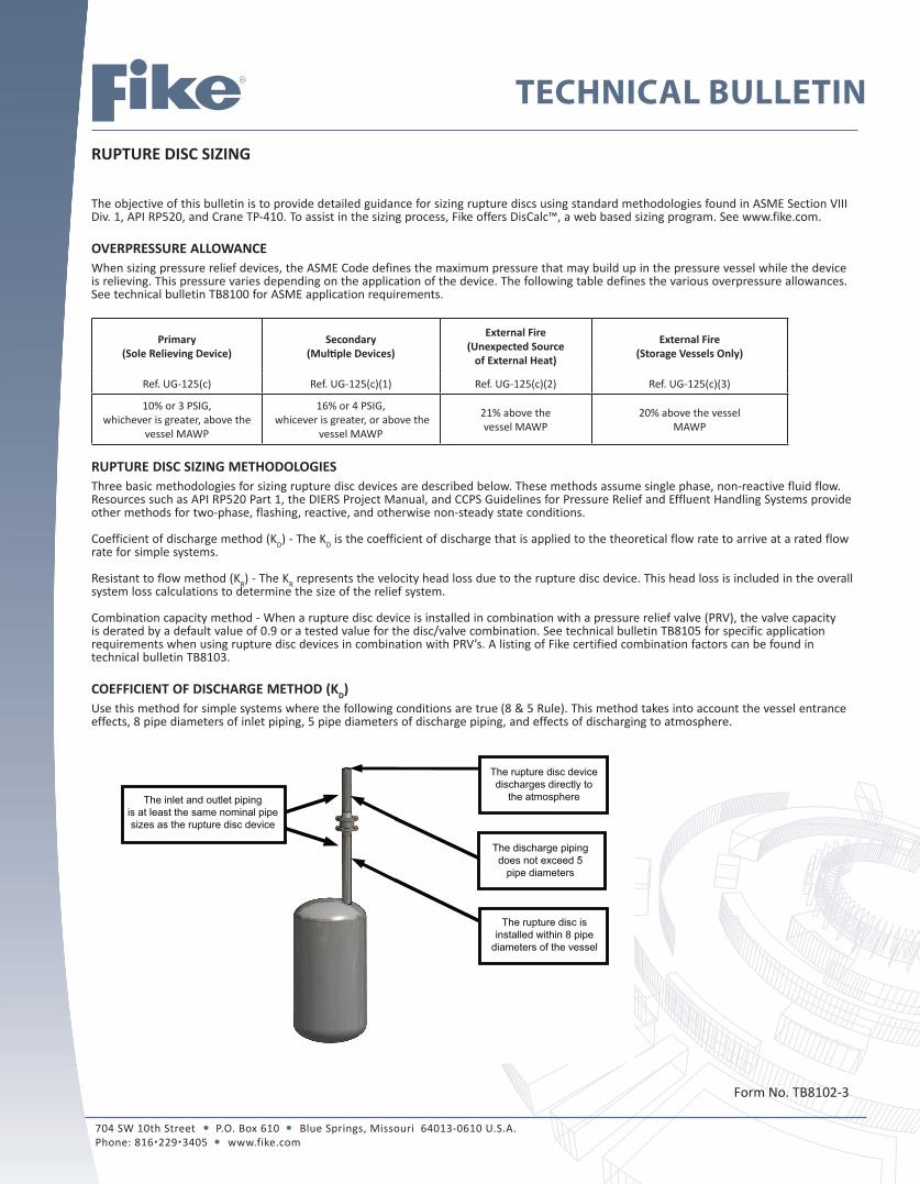
COEFFICIENT OF DISCHARGE METHOD (KD)Use this method for simple systems where the following conditions are true (8 & 5 Rule). This method takes into account the vessel entrance effects, 8 pipe diameters of inlet piping, 5 pipe diameters of discharge piping, and effects of discharging to atmosphere.
The inlet and outlet piping is at least the same nominal pipe sizes as the rupture disc device
The rupture disc devicedischarges directly to
the atmosphere
The discharge pipingdoes not exceed 5
pipe diameters
The rupture disc isinstalled within 8 pipe
diameters of the vessel

2 of 9
GAS/VAPOR SIZINGDetermination of Critical vs. Subcritical Flow per API RP520
Critical Pressure:
Calculations per ASME Section VIII (assumes critical flow)
Critical Flow:
Calculation per API RP520 Subcritical Flow: Critical Flow:
TABLE 1 TABLE 2 Gas Constants Gas Flow Constant C for Sonic Flow STEAM SIZING
k C k C
1.00 315 1.40 356
1.02 318 1.42 358
1.04 320 1.44 360
1.06 322 1.46 361
1.08 325 1.48 363
1.10 327 1.50 365
1.12 329 1.52 366
1.14 331 1.54 368
1.16 333 1.56 369
1.18 335 1.58 371
1.20 337 1.60 373
1.22 339 1.62 374
1.24 341 1.64 376
1.26 343 1.66 377
1.28 345 1.68 379
1.30 347 1.70 380
1.32 349 2.00 400
1.34 351 2.10 406
1.36 352 2.20 412
1.38 354
Page 2:
)1/(
12
kk
cf kPP
If cfe PP use critical flow equations
MZT
PCKWA
ZTMPACKW
D
D
eD
eD
eD
PPPSGZT
KFVA
PPPMZT
KFVA
PPPMZT
KFWA
2
2
2
864
4645
735
PCKSGZTVA
PCKMZTVA
MZT
PCKWA
D
D
D
175.1
32.6
W = rated flow capacity, (lb/hr) V = rated flow capacity, (SCFM) A = minimum net flow area, (sq. in.) C = constant based on the ratio of specific heats kk = cp/cvKD = coefficient of discharge 0.62 for rupture disc devices
F2 =
rrr
kk kk
k
11
1
/1/2
r = PPe
P = set pressure plus overpressure allowance plus atmospheric pressure (psia)
Pe = exit pressure, (psia) M = molecular weight SG = specific gravity of gas at standard conditions,
SG=1.00 for air at 14.7 psia and 60°F T = absolute temperature at inlet (R=°F + 460°F) Z = compressibility factor for corresponding to P and T.
use 1.0 if unknown.
Gas or Vapor Molecular Weight k = cp/cv
AirAcetic AcidAcetyleneAmmonia
ArgonBenzeneN-Butane
ISO- ButaneButane
Carbon MonoxideCarbon DisulfideCarbon Dioxide
ChlorineCyclohexane
EthaneEthyl AlcoholEthyl Chloride
EthyleneHelium
Hydrochloric AcidHydrogen
Hydrogen SulfideMethane
Methyl AlcoholMethyl Chloride
Natural Gas (Avg.)Nitric AcidNitrogenOxygenPentanePropane
Sulfur DioxideWater Vapor
28.9760
26.0417.03
4078.1
58.1258.1256.12876
44.0170.9
84.1630.0746.0764.5
28.054
36.52.01634.0716.0432.0450.48
19302832
72.1544.0964.0618.02
1.401.151.261.331.671.12
1.0941.0941.101.401.211.301.361.091.221.131.191.261.661.411.411.321.311.201.201.271.40
1.4041.401.071.131.29
1.324
Page 2:
)1/(
12
kk
cf kPP
If cfe PP use critical flow equations
MZT
PCKWA
ZTMPACKW
D
D
eD
eD
eD
PPPSGZT
KFVA
PPPMZT
KFVA
PPPMZT
KFWA
2
2
2
864
4645
735
PCKSGZTVA
PCKMZTVA
MZT
PCKWA
D
D
D
175.1
32.6
W = rated flow capacity, (lb/hr) V = rated flow capacity, (SCFM) A = minimum net flow area, (sq. in.) C = constant based on the ratio of specific heats kk = cp/cvKD = coefficient of discharge 0.62 for rupture disc devices
F2 =
rrr
kk kk
k
11
1
/1/2
r = PPe
P = set pressure plus overpressure allowance plus atmospheric pressure (psia)
Pe = exit pressure, (psia) M = molecular weight SG = specific gravity of gas at standard conditions,
SG=1.00 for air at 14.7 psia and 60°F T = absolute temperature at inlet (R=°F + 460°F) Z = compressibility factor for corresponding to P and T.
use 1.0 if unknown.

3 of 9
STEAM SIZINGCalculation per ASME Section VIII
Steam:
Calculation per API RP520 Steam:
TABLE 3Superheat Correction Factors, KSH (API RP520 Part 1 Table 9)
Burst Pressure
(psig)
Temperature °F
300 400 500 600 700 800 900 1000 1100 1200
15 1.00 .98 .93 .88 .84 .80 .77 .74 .72 .70
20 1.00 .98 .93 .88 .84 .80 .77 .74 .72 .70
40 1.00 .99 .93 .88 .84 .81 .77 .74 .72 .70
60 1.00 .99 .93 .88 .84 .81 .77 .75 .72 .70
80 1.00 .99 .93 .88 .84 .81 .77 .75 .72 .70
100 1.00 .99 .94 .89 .84 .81 .77 .75 .72 .70
120 1.00 .99 .94 .89 .84 .81 .78 .75 .72 .70
140 1.00 .99 .94 .89 .85 .81 .78 .75 .72 .70
160 1.00 .99 .94 .89 .85 .81 .78 .75 .72 .70
180 1.00 .99 .94 .89 .85 .81 .78 .75 .72 .70
200 1.00 .99 .95 .89 .85 .81 .78 .75 .72 .70
220 1.00 .99 .95 .89 .85 .81 .78 .75 .72 .70
240 - 1.00 .95 .90 .85 .81 .78 .75 .72 .70
260 - 1.00 .95 .90 .85 .81 .78 .75 .72 .70
280 - 1.00 .96 .90 .85 .81 .78 .75 .72 .70
300 - 1.00 .96 .90 .85 .81 .78 .75 .72 .70
350 - 1.00 .96 .90 .86 .82 .78 .75 .72 .70
400 - 1.00 .96 .91 .86 .82 .78 .75 .72 .70
500 - 1.00 .96 .92 .86 .82 .78 .75 .73 .70
600 - 1.00 .97 .92 .87 .82 .79 .75 .73 .70
800 - - 1.00 .95 .88 .83 .79 .76 .73 .70
1000 - - 1.00 .96 .89 .84 .78 .76 .73 .71
1250 - - 1.00 .97 .91 .85 .80 .77 .74 .71
1500 - - - 1.00 .93 .86 .81 .77 .74 .71
1750 - - - 1.00 .94 .86 .81 .77 .73 .70
2000 - - - 1.00 .95 .86 .80 .76 .72 .69
2500 - - - 1.00 .95 .85 .78 .73 .69 .66
3000 - - - - 1.00 .82 .74 .69 .65 .62
Page 3:
ND
ND
KKPWA
KKPAW
⋅⋅⋅=
⋅⋅⋅⋅=
5.51
5.51
SHND KKKPWA
⋅⋅⋅⋅=
5.51
NK = Correction factor for steam
NK = when ≤P 1500 psia
NK = ⎟⎠⎞
⎜⎝⎛
−−
10612292.010001906.0
PP
when P > 1500 psia and ≤P 3200 psia
SHK = See Table 3 for superheat steam correction factors. For saturated steam use 1.0.
Page 3:
ND
ND
KKPWA
KKPAW
⋅⋅⋅=
⋅⋅⋅⋅=
5.51
5.51
SHND KKKPWA
⋅⋅⋅⋅=
5.51
NK = Correction factor for steam
NK = when ≤P 1500 psia
NK = ⎟⎠⎞
⎜⎝⎛
−−
10612292.010001906.0
PP
when P > 1500 psia and ≤P 3200 psia
SHK = See Table 3 for superheat steam correction factors. For saturated steam use 1.0.
Page 3:
ND
ND
KKPWA
KKPAW
⋅⋅⋅=
⋅⋅⋅⋅=
5.51
5.51
SHND KKKPWA
⋅⋅⋅⋅=
5.51
NK = Correction factor for steam
NK = when ≤P 1500 psia
NK = ⎟⎠⎞
⎜⎝⎛
−−
10612292.010001906.0
PP
when P > 1500 psia and ≤P 3200 psia
SHK = See Table 3 for superheat steam correction factors. For saturated steam use 1.0.
4 of 9
LIQUID SIZINGCalculation per ASME Section VIII
Water:
Calculation per API RP520
Non-viscous liquid:
Viscous liquid:
For viscous liquid sizing, first calculate AR using KV of 1.0. Apply the area A of the next larger size disc to the Reynoldsnumber calculations to arrive at KV. Then re-calculaterequired area AV using the derived KV.
RESISTANCE TO FLOW METHOD (KR) Use this method when the 8 & 5 Rule does not apply and the rupture disc is not installed in combination with a pressure relief valve. This type of calculation is the responsibility of the system designer. DisCalcTM does not perform this type of calculation.
Characteristics of the Resistance to Flow Method• Sizing is done on a relief system basis not by capacity of individual components• Rupture disc is treated as another component in the relief system• Each device or family of devices has a unit-less resistance value (KR) that represents the expected resistance to flow that is independent
of the fluid flowing• System relief capacity must be multiplied by a factor of 0.90
Types of KR
Because many rupture discs have different opening characteristics depending on whether they are opened with a compressed vapor or incompressible liquid, there are certified KR values that are denoted by the applicable service media. The KR values for different media are a result of differences in how the rupture disc opens with different media and test methods that have been standardized in ASME PTC25. A list of Fike certified KR factors can be found in technical bulletin TB8104.
• Air or gas service – KRG Use KRG when the media is a gas or vapor, or when the media is liquid but there is a significant vapor volume directly in contact with the disc at the time of rupture
• Liquid service – KRL Use KRL when the media is liquid and the liquid is against the disc at the time of rupture
• Air or gas and liquid service – KRGL KRGL can be used for any service conditions
The following examples will illustrate how KR values are used to establish the flow capacity of a pressure relief piping system.
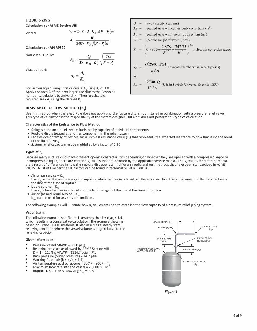
Vapor SizingThe following example, see Figure 1, assumes that k = cp/cv = 1.4 which results in a conservative calculation. The example shown is based on Crane TP-410 methods. It also assumes a steady state relieving condition where the vessel volume is large relative to the relieving capacity.
Given information:• Pressure vessel MAWP = 1000 psig• Relieving pressure as allowed by ASME Section VIII
Div. 1 = 110% x MAWP = 1114.7 psia = P’1• Back pressure (outlet pressure) = 14.7 psia • Working fluid - air (k = cp/cv = 1.4)• Air temperature at disc rupture = 500°F = 960R = T1• Maximum flow rate into the vessel = 20,000 SCFM• Rupture Disc - Fike 3” SRX-GI g KRG = 0.99
Page 4:
( )
( )wPPKWA
wPPKAW
eD
eD
−⋅=
−⋅⋅=
2407
2407
eVDR PP
SGKK
QA−⋅⋅
=38
Q = rated capacity, (gal.min) AR = required Area without viscosity corrections (in2)
Av = required Area with viscosity corrections (in2)W = Specific weight of water, (lb/ft3)
Kv =0.1
5.15.075.342878.29935.0
−
⎟⎠⎞
⎜⎝⎛ ++
RR, viscosity correction factor
Re = ( )
AuSGQ ⋅2800
Reynolds Number (u is in centipoises)
or
Re = AU
Q⋅12700 (U is in Saybolt Universal Seconds, SSU)
V
RV K
AA =
Figure 1

5 of 9
DETERMINE THE TOTAL PIPING SYSTEM RESISTANCE FACTOR:
Piping Component or Feature Flow Resistance Value (K) Reference
Entrance - Sharp Edged K1 = .50 Crane 410 pg A-29
1 ft of 3” Sch. 40 Pipe K2 = .07 K=fL/D: f = .018 (Crane 410 Pg A-26 L= 1 ft. ID = 3.068/12 ft
Fike 3” SRX-GI Rupture Disc KRG = 0.99 National Board Cert. No. FIK-M80277
20 ft or 3” Sch. 40 Pipe K3 = 1.41 K=fL/D: f = .018 (Crane 410 Pg A-26 L= 1 ft. ID = 3.068/12 ft
3” Sch. 40 Standard 90° Elbow K4 = 0.54 Crane 410 Pg A-29
40 ft of 3” Sch. 40 Pipe K5 = 2.82 K=fL/D: f = .018 (Crane 410 Pg A-26 L= 1 ft. ID = 3.068/12 ft
Pipe exit - Sharp Edged K6 = 1.00 Crane 410 Pg A-29
Total System Flow Resistance KT = 7.33 KT = K1 + K2 + KRG+ K3 + K4 + K5 + K6
The Darcy Equation defines the discharge of compressible fluids through valves, fittings and pipes. Since the flow rate into the example vessel is defined in SCFM, the following form of the Darcy equation is used:
Crane Equation 3-20Page 5:
SGTKPPdYq m ⋅⋅⋅Δ
⋅⋅=1
12 '678'
q’m = rate of flow in cubic feet per minute at standard
conditions, (SCFM) (14.7 psia and 60°F) Y = net expansion factor for compressible flow through orifices, nozzles and pipes (Crane 410 Pg A-22) d = internal diameter of pipe, (in) ΔP = change in pressure entrance to exit, (psia) P’1 = pressure at entrance, (psia) K = loss coefficient T1 = absolute temperature at entrance, (R)
Page 5:
SGTKPPdYq m ⋅⋅⋅Δ
⋅⋅=1
12 '678'
q’m = rate of flow in cubic feet per minute at standard
conditions, (SCFM) (14.7 psia and 60°F) Y = net expansion factor for compressible flow through orifices, nozzles and pipes (Crane 410 Pg A-22) d = internal diameter of pipe, (in) ΔP = change in pressure entrance to exit, (psia) P’1 = pressure at entrance, (psia) K = loss coefficient T1 = absolute temperature at entrance, (R)
6 of 9
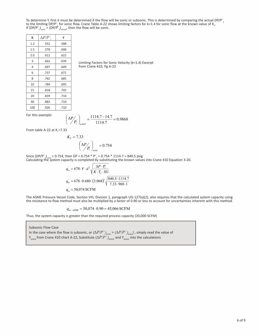
To determine Y, first it must be determined if the flow will be sonic or subsonic. This is determined by comparing the actual DP/P’1 to the limiting DP/P’1 for sonic flow. Crane Table A-22 shows limiting factors for k=1.4 for sonic flow at the known value of KT. If (DP/P’1)sonic < (DP/P’1)actual, then the flow will be sonic.
K DP/P’1Y
1.2 .552 .588
1.5 .576 .606
2.0 .612 .622
3 .662 .639
4 .697 .649
6 .737 .671
8 .762 .685
10 .784 .695
15 .818 .702
20 .839 .710
40 .883 .710
100 .926 .710
For this example:
From table A-22 at KT=7.33
Since (DP/P’1)sonic = 0.754, then DP = 0.754 * P’1 = 0.754 * 1114.7 = 840.5 psigCalculating the system capacity is completed by substituting the known values into Crane 410 Equation 3-20.
The ASME Pressure Vessel Code, Section VIII, Division 1, paragraph UG-127(a)(2), also requires that the calculated system capacity using the resistance to flow method must also be multiplied by a factor of 0.90 or less to account for uncertainties inherent with this method.
Thus, the system capacity is greater than the required process capacity (20,000 SCFM)
Limiting Factors for Sonic Velocity (k=1.4) Excerpt from Crane 410, Pg A-22
Page 6
9868.07.1114
7.147.1114'
1=
−=⎟
⎠⎞
⎜⎝⎛Δ
actualPP
33.7=TK
754.0'1
=⎟⎠⎞
⎜⎝⎛Δ
sonicP
P
Since ( ) ,62.7'1 =Δ actualPP then 5.8407.1114754.0754.0 '
1 =⋅=⋅=Δ PP psi
SGTKPPdYqm ⋅⋅⋅Δ
⋅⋅=1
'12' 678
( )196033.77.11145.840068.3680.0678 2'
⋅⋅⋅
⋅⋅=mq
074,50' =mq SCFM
066,4590.0074,50' =⋅=−ASMEmq SCFMSubsonic Flow CaseIn the case where the flow is subsonic, or(DP/P’1)sonic>(DP/P’1)actual , simply read the value of Yactualfrom Crane 410 chart A-22, Substitute(DP/P’1)actualand Yactualinto the calculations
Page 6
9868.07.1114
7.147.1114'
1=
−=⎟
⎠⎞
⎜⎝⎛Δ
actualPP
33.7=TK
754.0'1
=⎟⎠⎞
⎜⎝⎛Δ
sonicP
P
Since ( ) ,62.7'1 =Δ actualPP then 5.8407.1114754.0754.0 '
1 =⋅=⋅=Δ PP psi
SGTKPPdYqm ⋅⋅⋅Δ
⋅⋅=1
'12' 678
( )196033.77.11145.840068.3680.0678 2'
⋅⋅⋅
⋅⋅=mq
074,50' =mq SCFM
066,4590.0074,50' =⋅=−ASMEmq SCFM
Page 6
9868.07.1114
7.147.1114'
1=
−=⎟
⎠⎞
⎜⎝⎛Δ
actualPP
33.7=TK
754.0'1
=⎟⎠⎞
⎜⎝⎛Δ
sonicP
P
Since ( ) ,62.7'1 =Δ actualPP then 5.8407.1114754.0754.0 '
1 =⋅=⋅=Δ PP psi
SGTKPPdYqm ⋅⋅⋅Δ
⋅⋅=1
'12' 678
( )196033.77.11145.840068.3680.0678 2'
⋅⋅⋅
⋅⋅=mq
074,50' =mq SCFM
066,4590.0074,50' =⋅=−ASMEmq SCFM
Page 6
9868.07.1114
7.147.1114'
1=
−=⎟
⎠⎞
⎜⎝⎛Δ
actualPP
33.7=TK
754.0'1
=⎟⎠⎞
⎜⎝⎛Δ
sonicP
P
Since ( ) ,62.7'1 =Δ actualPP then 5.8407.1114754.0754.0 '
1 =⋅=⋅=Δ PP psi
SGTKPPdYqm ⋅⋅⋅Δ
⋅⋅=1
'12' 678
( )196033.77.11145.840068.3680.0678 2'
⋅⋅⋅
⋅⋅=mq
074,50' =mq SCFM
066,4590.0074,50' =⋅=−ASMEmq SCFM

7 of 9
LIQUID SIZING For this example Figure 2 is assumed, water will be considered the flow media. The example shown is based on Crane TP-410 methods. It also assumes a steady state relieving condition where the vessel volume is large relative to the relieving capacity.
Given information:• Pressure vessel MAWP = 500 psig• Relieving pressure as allowed by
ASME Section VIII Div. 1 = 110% x MAWP = 550 psig = P1• Back pressure (outlet pressure) = 1 psig = P2• Working fluid - water• Temperature = 70°F• Maximum flow rate into the vessel = 50 ft3/min• Rupture disc - Fike 2” SRL-GI → KRGL = 0.59
From Crane 410:
“Bernoulli’s Theorem is a means of expressing the application of the law of conservation of energy to the flow of fluids in a conduit (piping). The total energy at any particular point, above some arbitrary horizontal datum plane, is equal to the sum of the elevation head (Z), the pressure head (P), the velocity head (V).
In real applications, there are energy losses in piping systems between states (or location) 1 and 2. Those losses are accounted for in the term hL, which are predominately frictional head losses. The energy balance is then expressed:
Crane Equation 1-3
As in the previous example, head losses due to friction in the piping and the head losses due to fittings are proportional to the sum of the flow resistances:
Since the acutal head loss is velocity dependent,
Page 7
Lhg
VPZg
VPZ +⋅
+⋅
+=⋅
+⋅
+2
1442
144 22
2
22
21
1
11 ρρ
Z1 and Z2 = elevation head at states 1 and 2 (ft) P1 and P2 = pressure at states 1 and 2 (psig) V1 and V2 = velocity at states 1 and 2 (ft/sec) ρ1 and ρ2 = fluid density at states 1 and 2 (lb/ft3)g = acceleration due to gravity (32.2 ft/sec2)hL = frictional head loss (ft)
KhL ∑=
⎟⎟⎠
⎞⎜⎜⎝
⎛⋅
∑=g
VKhL 2
2
Figure 2
8 of 9
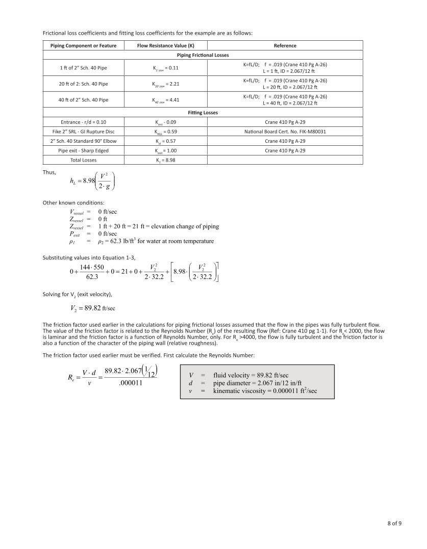
Frictional loss coefficients and fitting loss coefficients for the example are as follows:
Piping Component or Feature Flow Resistance Value (K) Reference
Piping Frictional Losses
1 ft of 2” Sch. 40 Pipe K1’ pipe = 0.11 K=fL/D; f = .019 (Crane 410 Pg A-26) L = 1 ft, ID = 2.067/12 ft
20 ft of 2: Sch. 40 Pipe K20’ pipe = 2.21 K=fL/D; f = .019 (Crane 410 Pg A-26) L = 20 ft, ID = 2.067/12 ft
40 ft of 2” Sch. 40 Pipe K40’ pipe = 4.41 K=fL/D; f = .019 (Crane 410 Pg A-26) L = 40 ft, ID = 2.067/12 ft
Fitting Losses
Entrance - r/d = 0.10 Kent - 0.09 Crane 410 Pg A-29
Fike 2” SRL - GI Rupture Disc KRGL = 0.59 National Board Cert. No. FIK-M80031
2” Sch. 40 Standard 90° Elbow Kel = 0.57 Crane 410 Pg A-29
Pipe exit - Sharp Edged Kexit = 1.00 Crane 410 Pg A-29
Total Losses KT = 8.98
Thus,
Other known conditions:
Substituting values into Equation 1-3,
Solving for V2 (exit velocity),
The friction factor used earlier in the calculations for piping frictional losses assumed that the flow in the pipes was fully turbulent flow. The value of the friction factor is related to the Reynolds Number (Re) of the resulting flow (Ref: Crane 410 pg 1-1). For Re< 2000, the flow is laminar and the friction factor is a function of Reynolds Number, only. For Re >4000, the flow is fully turbulent and the friction factor is also a function of the character of the piping wall (relative roughness).
The friction factor used earlier must be verified. First calculate the Reynolds Number:
Page 8
⎟⎟⎠
⎞⎜⎜⎝
⎛⋅
=g
VhL 298.8
2
Vvessel = 0 ft/sec Zvessel = 0 ftZvessel = 1 ft + 20 ft = 21 ft = elevation change of piping Pexit = 0 ft/secρ1 = ρ2 = 62.3 lb/ft3 for water at room temperature
⎥⎦
⎤⎢⎣
⎡⎟⎟⎠
⎞⎜⎜⎝
⎛⋅
⋅+⋅
++=+⋅
+2.322
98.82.322
02103.625501440
22
22 VV
82.892 =V ft/sec
Page 8
⎟⎟⎠
⎞⎜⎜⎝
⎛⋅
=g
VhL 298.8
2
Vvessel = 0 ft/sec Zvessel = 0 ftZvessel = 1 ft + 20 ft = 21 ft = elevation change of piping Pexit = 0 ft/secρ1 = ρ2 = 62.3 lb/ft3 for water at room temperature
⎥⎦
⎤⎢⎣
⎡⎟⎟⎠
⎞⎜⎜⎝
⎛⋅
⋅+⋅
++=+⋅
+2.322
98.82.322
02103.625501440
22
22 VV
82.892 =V ft/sec
Page 8
⎟⎟⎠
⎞⎜⎜⎝
⎛⋅
=g
VhL 298.8
2
Vvessel = 0 ft/sec Zvessel = 0 ftZvessel = 1 ft + 20 ft = 21 ft = elevation change of piping Pexit = 0 ft/secρ1 = ρ2 = 62.3 lb/ft3 for water at room temperature
⎥⎦
⎤⎢⎣
⎡⎟⎟⎠
⎞⎜⎜⎝
⎛⋅
⋅+⋅
++=+⋅
+2.322
98.82.322
02103.625501440
22
22 VV
82.892 =V ft/sec
Page 8
⎟⎟⎠
⎞⎜⎜⎝
⎛⋅
=g
VhL 298.8
2
Vvessel = 0 ft/sec Zvessel = 0 ftZvessel = 1 ft + 20 ft = 21 ft = elevation change of piping Pexit = 0 ft/secρ1 = ρ2 = 62.3 lb/ft3 for water at room temperature
⎥⎦
⎤⎢⎣
⎡⎟⎟⎠
⎞⎜⎜⎝
⎛⋅
⋅+⋅
++=+⋅
+2.322
98.82.322
02103.625501440
22
22 VV
82.892 =V ft/sec
Page 9
( )000011.
121067.282.89 ⋅
=⋅
=v
dVRe
V = fluid velocity = 89.82 ft/sec d = pipe diameter = 2.067 in/12 in/ft v = kinematic viscosity = 0.000011 ft2/sec
VAQ ⋅=
Q = volumetric flow rate (ft3/sec)A = area of pipe (ft2) - πd2/4 V = fluid velocity (ft/sec)
Q = ( ) 82.8912067.2
42⋅⋅
π
Qcalc = 2.09 ft3/sec = 125.6 ft3/min
If the flow had been laminar, 2000<eR the friction factor is calculated as:
Qrated = Qcalc ( ) 04.113)90.0(6.12590.0 =⋅=⋅ ft3/min
eRf 64=
9 of 9
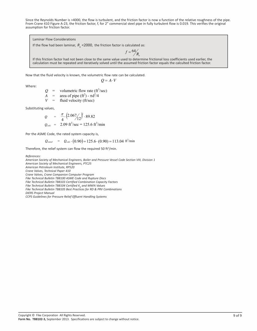
Since the Reynolds Number is >4000, the flow is turbulent, and the friction factor is now a function of the relative roughness of the pipe. From Crane 410 Figure A-23, the friction factor, f, for 2” commercial steel pipe in fully turbulent flow is 0.019. This verifies the original assumption for friction factor.
Now that the fluid velocity is known, the volumetric flow rate can be calculated.
Where:
Substituting values,
Per the ASME Code, the rated system capacity is,
Therefore, the relief system can flow the required 50 ft3/min.
References:American Society of Mechanical Engineers, Boiler and Pressure Vessel Code Section VIII, Division 1American Society of Mechanical Engineers, PTC25American Petroleum Institute, RP520Crane Valves, Technical Paper 410Crane Valves, Crane Companion Computer ProgramFike Technical Bulletin TB8100 ASME Code and Rupture DiscsFike Technical Bulletin TB8103 Certified Combination Capacity FactorsFike Technical Bulletin TB8104 Certified KR and MNFA Values Fike Technical Bulletin TB8105 Best Practices for RD & PRV CombinationsDIERS Project ManualCCPS Guidelines for Pressure Relief Effluent Handling Systems
Copyright © Fike Corporation All Rights Reserved.Form No. TB8102-3, September 2013. Specifications are subject to change without notice.
Laminar Flow ConsiderationsIf the flow had been laminar,Re <2000,the friction factor is calculated as:
If this friction factor had not been close to the same value used to determine frictional loss coefficients used earlier, the calculation must be repeated and iteratively solved until the assumed friction factor equals the calculted friction factor.
Page 9
( )000011.
121067.282.89 ⋅
=⋅
=v
dVRe
V = fluid velocity = 89.82 ft/sec d = pipe diameter = 2.067 in/12 in/ft v = kinematic viscosity = 0.000011 ft2/sec
VAQ ⋅=
Q = volumetric flow rate (ft3/sec)A = area of pipe (ft2) - πd2/4 V = fluid velocity (ft/sec)
Q = ( ) 82.8912067.2
42⋅⋅
π
Qcalc = 2.09 ft3/sec = 125.6 ft3/min
If the flow had been laminar, 2000<eR the friction factor is calculated as:
Qrated = Qcalc ( ) 04.113)90.0(6.12590.0 =⋅=⋅ ft3/min
eRf 64=