lafleur et al. - 2015 - rapid and simple preparation of thiol–ene emulsion
TRANSCRIPT
www.rsc.org/loc
ISSN 1473-0197
Lab on a ChipMiniaturisation for chemistry, physics, biology, materials science and bioengineering
PAPERJosiane P. Lafleur et al.Rapid and simple preparation of thiol–ene emulsion-templated monoliths and their application as enzymatic microreactors
Volume 15 Number 10 21 May 2015 Pages 2149–2342
Lab on a Chip
PAPER
2162 | Lab Chip, 2015, 15, 2162–2172 This journal is © The R
aDepartment of Pharmacy, University of Copenhagen, Copenhagen, Denmark.
E-mail: [email protected]; Tel: (+45) 3532 0398bDepartment of Biological and Biochemical Sciences, University of Pardubice,
Pardubice, Czech Republicc Institute of Analytical Chemistry of the ASCR, v.v.i., Brno, Czech Republicd Department of Pharmacy, Université de Liège, Liège, Belgium
† Electronic supplementary information (ESI) available. See DOI: 10.1039/c5lc00224a
Cite this: Lab Chip, 2015, 15, 2162
Received 23rd February 2015,Accepted 26th March 2015
DOI: 10.1039/c5lc00224a
www.rsc.org/loc
Rapid and simple preparation of thiol–eneemulsion-templated monoliths and theirapplication as enzymatic microreactors†
Josiane P. Lafleur,*a Silja Senkbeil,a Jakub Novotny,bc Gwenaël Nys,d
Nanna Bøgelund,a Kasper D. Rand,a Frantisek Foretc and Jörg P. Kuttera
A novel, rapid and simple method for the preparation of emulsion-templated monoliths in microfluidic
channels based on thiol–ene chemistry is presented. The method allows monolith synthesis and anchoring
inside thiol–ene microchannels in a single photoinitiated step. Characterization by scanning electron
microscopy showed that the methanol-based emulsion templating process resulted in a network of highly
interconnected and regular thiol–ene beads anchored solidly inside thiol–ene microchannels. Surface area
measurements indicate that the monoliths are macroporous, with no or little micro- or mesopores. As a
demonstration, galactose oxidase and peptide-N-glycosidase F (PNGase F) were immobilized at the surface
of the synthesized thiol–ene monoliths via two different mechanisms. First, cysteine groups on the protein
surface were used for reversible covalent linkage to free thiol functional groups on the monoliths. Second,
covalent linkage was achieved via free primary amino groups on the protein surface by means of thiol–ene
click chemistry and L-ascorbic acid linkage. Thus prepared galactose oxidase and PNGase F microreactors
demonstrated good enzymatic activity in a galactose assay and the deglycosilation of ribonuclease B,
respectively.
Introduction
High surface area materials are essential in many chemical,biological and analytical procedures. They can be used assolid supports for biomolecules in enzymaticmicroreactors,1–3 as stationary phases in chromatography4,5
and in sample preparation steps such as extraction and pre-concentration.6 Commercially, sorbents are available asmicrometer-sized beads made of materials such as silica oragarose, which can either be bought pre-packed into columnsor packed manually. Optimal packing is not trivial to achieveand in practice, even the best packed columns contain 30–40% void volume in addition to the internal porosity of thebeads.7 Packing columns in microfluidic chips is even morechallenging. Porous polymer monoliths offer an attractivealternative to traditional packed beds. The processability ofpolymers can be used to easily generate porous monolithsand beads from a mixture of monomers, free radical initiators
and porogenic solvents. Heterogeneous emulsions consistingof at least one immiscible liquid dispersed in another in theform of droplets can be used as templates for the productionof porous materials, so-called emulsion-templated monoliths,where either the dispersed or continuous phase is polymer-ized.8 In the case of high internal phase emulsion templatedmonoliths (polyHIPEs), the internal phase (usually formingmore than 74% v/v of the emulsion), is dispersed as discretedroplets within a continuous, less abundant external phase.9
These monolithic materials can be prepared using a very sim-ple process carried out within the confines of a closed con-tainer, such as a microfluidic channel. However, routineapplications in microfluidic devices still face some challenges.Poor adhesion of the monolith inside native unmodified poly-meric microchannels and monolith shrinkage are recurringproblems. This can cause a formed monolith to detach fromthe microchannel walls and create, for example, large deadvolumes. Therefore, the preparation of porous polymer mono-liths and their anchoring inside microfluidic channels is stillan active area of research.
The attractive surface properties of thiol–ene (TE) poly-mers combined with their ease of processing have madethem an increasingly popular choice in the fabrication ofmicrofluidic devices for bioanalytical applications. Micro-fluidic devices have been fabricated with commercially avail-able TE-based photo-curable adhesives (NOA, Norland Optical
oyal Society of Chemistry 2015

Lab on a Chip Paper
Adhesives, Norland Products Inc, USA)10–16 as well as withcustom formulations prepared in-house. Alterations in thenature and/or stoichiometry of reactants in customized for-mulations provide increased control over elastic modulus17
and surface chemistry.18 Carlborg et al.19 introduced a newclass of TE materials, “off-stoichiometry” TE (OSTE), achievedby altering extensively the stoichiometric ratios of the initialreactant monomers. The result is a large excess of functionalgroups, either thiols or enes, on the polymer surfaces andmarked variations in material bulk properties. The functionalgroups present at the surface of OSTE polymers have beenused as anchors for the covalent attachment of biomole-cules20,21 and for bonding.22,23
Although TE-based microfluidic devices have received ahigh level of attention in recent years, the ability of TE poly-mers to form in-chip porous monoliths remains unexplored.The advantages of TE and OSTE in the preparation of mono-liths are numerous. The tunable OSTE surface chemistry canprovide for a simple means of covalently anchoring mono-liths to microchannel walls without any prior surface activa-tion as well as for a wide variety of photoinitiatedfunctionalization reactions to occur at the surface of themonoliths. Moreover, the TE click chemistry reaction24–26
offers high atom economy, a large thermodynamic drivingforce and simple/mild reaction conditions27 as well as bio-orthogonality,28 making it an ideal reaction scheme for theimmobilization of biomolecules on solid supports.20,21,29
Immobilized enzyme microreactors are especially interest-ing since these tend to exhibit much higher efficiency com-pared to the corresponding reactions in solution.2 A widevariety of chemical reactions are available for the immobiliza-tion of biomolecules to TE solid supports. TE click chemistryallows for simple and rapid photoinitiated modification ofthe solid support for the covalent irreversible linkage of pro-teins through their amino groups. Additionally, manyenzymes and proteins possess free thiol groups at their sur-face, which are available for interactions with the thiolgroups present at the surface of OSTE monoliths, allowingtheir straightforward and reversible immobilization throughdirect disulfide linkage. Finally, in proteins where cysteineresidues form intramolecular disulfide bonds, immobiliza-tion can proceed through thiol–disulfide exchange30,31 orphotonic activation of disulfide bridges.32 The thiol–disulfideexchange chemistry offers several advantages as covalentdisulfide bonds can form efficiently at neutral pH in aqueoussolutions and can be easily reversed with a reducing agent33
for the regeneration of the microreactor. TE and thiol–yne(TY) polyHIPEs have been prepared in bulk,34–38 with func-tional monomers added in situ35,37 or in a post-functionalization step performed on the ground monolithpowder.38 Droplet-based microfluidic devices have been usedto prepare NOA porous polymer microspheres39 as well asmacroporous and non-porous TE/TY polymer beads.40 Inboth cases, droplets were cured individually and collected asbeads from the microfluidic device. Finally, Liu et al. usedTE41 and TY42 photoinduced polymerization for the
This journal is © The Royal Society of Chemistry 2015
preparation of macroporous monoliths in fused-silica capil-laries for liquid chromatography.
The method reported here allows monolith synthesis andanchoring inside TE microchannels in a single and rapidphotoinitiated step. We demonstrate that the thus preparedmonoliths can be post-functionalized reversibly through theformation of disulfide bonds with enzymes or permanentlyusing further photoinitiated TE click chemistry to establishan irreversible covalent linkage to enzymes via their freeamino groups. As a demonstration, enzymatic microreactorsfeaturing immobilized galactose oxidase and PNGase F wereprepared and characterized by performing a galactose assayand the deglycosylation of ribonuclease B, respectively.
ExperimentalReagents
Pentaerythritol-tetrakisIJ3-mercaptopropionate) (“tetrathiol”),triallyl-1,3,5-triazine-2,4,6IJ1H,3H,5H)-trione (“triallyl”), 2‐(bocamino)ethanethiol, L-ascorbic acid (ASA), galactose-oxidasefrom Dactylium dendroides [50 U ml−1], horseradish peroxi-dase (HRP, lyophilized powder, 150 U mg−1), PNGase F, nin-hydrin, D-galactose, D-IJ+)-glucose, ribonuclease B (RNase Bfrom bovine pancreas (50 Kunitz units per mg protein)), 10-acetyl-3,7-dihydroxyphenoxazine (ADHP), Tween 20 and 5,5′-dithiobisIJ2-nitrobenzoic acid) (DTNB) were obtained fromSigma Aldrich (Brøndby, DK). Lucirin TPO-L (ethyl-2, 4, 6-tri-methylbenzoylphenyl phosphinate) was obtained from BASF(Hardmatt, CH). Sylgard 184 – polyIJdimethylsiloxane) (PDMS)elastomer kit was obtained from Dow Corning (Midland, MI,USA). Hypermer B246 and Span 80 surfactants were obtainedfrom Croda International Plc (Snaith, UK)
Device fabrication
A two-step replica molding process was used to fabricate thechips. Chip designs were drawn with computer-aided-designsoftware (Autodesk Inventor Professional 2014, San Rafael,CA, USA). The devices featured channels 500 μm wide by 200μm deep. Chips used for fluorescence measurements fea-tured an 800 μm deep detection chamber. The internalvolume of the chips was 5 μl. MicromilledpolyIJmethylmethacrylate) (PMMA) masters as well aspolyIJtetrafluoroethylene) chip holders featuring injectionports were manufactured by high precision milling (Minitech3, Minitech Machinery Corp., Norcross, GA, USA). PDMSmolds for TE casting were prepared from the PMMA mastersand cured at 80 °C for 2 hours.
The TE monomers (tetrathiol and triallyl) were mixed invarious stoichiometric ratios and poured into PDMS moldsprior to exposure to UV light (25 s, 160 mW cm−2 at 365 nm,Dymax EC 5000 Series UV curing flood lamp, Dymax Corp,Torrington, CT). After curing, the TE parts were peeled offfrom the soft PDMS molds. No photoinitiator was used tominimize chip auto-fluorescence. The absence of photo-initiator was compensated for by the high output of the UVflood lamp at wavelengths below 300 nm. Microfluidic chips
Lab Chip, 2015, 15, 2162–2172 | 2163

Lab on a ChipPaper
were bonded immediately after production, while a thin layerof uncured TE is still present at the surface of the TE partsdue to the short exposure time and slight oxygen inhibitionin the absence of photoinitiator. Prior to bonding, the TEparts were warmed up for 10 minutes in an oven at 80 °Cand placed in conformal contact. A slight pressure wasapplied on the assembly to ensure uniform sealing and itwas exposed to UV light (2 × 1 min, 160 mW cm−2 at 365 nm)for bonding. The bonded microfluidic chip was placed in anoven under a weight (80 °C for 2 hours) and allowed to coolovernight before use. The final heating step helps keep theparts soft and in contact with each other to further enhancethe bonding.
Monoliths preparation
Two different types of emulsions were prepared in order toform various in-chip TE monoliths (Fig. 1). The emulsionswere prepared with either water or methanol as the porogen,resulting in markedly different monolith morphologies. Themonomeric composition of the organic phase of the emul-sions consisted of stoichiometric TE (S-TE), off-stoichiometric TE featuring 40% excess thiol groups (OSTE-thiol) or off-stoichiometric TE featuring 40% excess allylgroups (OSTE-allyl). The monolith formation conditions aresummarized in Table 1.
TE emulsions with water as the dispersed phase. Water(75–80% w/w) was added dropwise to a TE mixturecontaining a surfactant (Hypermer B246 or Span 80, 3–20%w/w of organic phase) and stirred using an overhead stirrer(300–500 rpm, 3–10 minutes) in order to create an emulsionwith water as the dispersed phase. In some cases, chloroformwas added to the organic phase (50% w/w). Photoinitiator(0.2% v/v Lucirin TPO-L) was added to the mixture prior toinjection in a TE microfluidic channel followed by curingunder UV collimated light (20 seconds, 20.5 mW cm−2 at 365nm, LS-100-3C2 near UV light source, Bachur & Associates,
2164 | Lab Chip, 2015, 15, 2162–2172
Fig. 1 Monolith preparation procedure. a) The emulsions are stirred witmicrofluidic chip and exposure to UV light. b) Depending on the surfactantor the continuous phase.
Santa Clara, CA, USA). Sections of the microfluidic chipwhere no monolith was desired were masked prior to expo-sure. Unreacted monomers were removed by rinsing thor-oughly with distilled deionized water (DDW).
Methanol emulsions with TE as the dispersed phase. TE/methanol mixtures were magnetically stirred (60–80% w/wmethanol, 1 min magnetic stirring at constant speed) inorder to create an emulsion with TE as the dispersed phase.Photoinitiator (0.2% v/v Lucirin TPO-L) was added to the mix-ture prior to injection in a TE microfluidic channel followedby curing under UV collimated light (7–20 s, 20.5 mW cm−2
at 365 nm). Sections of the microfluidic channel where nomonolith was desired were masked prior to exposure.Unreacted monomers and methanol were removed by rinsingthoroughly with DDW using a syringe pump (5 min at 10 μLmin−1). Microfluidic channels were sealed prior to storage toavoid drying of the monolith.
Monoliths characterization
Imaging and size distribution. Microfluidic chipscontaining TE monoliths were pried opened and allowed todry thoroughly before Scanning Electron Microscope (SEM)imaging. The opened microfluidic chips were taped to 12mm studs with graphite tape for conductivity. Samples weresputtered with gold (circa 4 nm) using a Cressington SputterCoater 108 (Cressington Scientific Instruments Ltd., Watford,UK) or a Leica EM ACE 200 (Leica Microsystems GmbH,Wetzlar, Germany) and imaged using a TM3030 benchtopSEM (Hitachi High-Technologies Europe GmbH, Krefeld, Ger-many) or an XL 30 FEG-SEM (Philips FEI, Oregon, USA). Par-ticle size distribution was determined by measuring thediameter of the individual beads with ImageJ (ImageJ, U. S.National Institutes of Health, Bethesda, MD, USA) with N =119–241 measured beads per sample. The means of the dis-tribution were compared by performing a single factorANOVA test (alpha = 0.05).
This journal is © The Royal Society of Chemistry 2015
h a magnetic mixer or an overhead mixer prior to injection in a TEand porogen present in the emulsion, the TE forms either the dispersed

Table 1 Summary of the monolith formation conditions. All monolith emulsions contained 0.2% v/v Lucirin TPO-L as a photoinitiator and were cured7–20 s (20.5 mW cm−2 at 365 nm)
Stirringconditions Stirring time Porogen Surfactant
Polymerphase Experiments performed
Interconnected beads (polymerized dispersed phase)MSa 40%of max.speed
1 min 60% w/wmethanol
None S-TEOSTE-allylOSTE-thiol
Specific surface area
MSa 40%of max.speed
1 min 80% w/wmethanol
None S-TEOSTE-allylOSTE-thiol
Specific surface area, SEM, enzymeimmobilization, removal of enzymes boundthrough thiols with TCEP
MSa 60%of max.speed
1 min 80% w/wmethanol
None S-TEOSTE-allylOSTE-thiol
SEM
PolyHIPE (polymerized continuous phase)MSa 40%of max.speed
3–10 minc 75% w/wwater
10% w/wSpan 80
S-TE + 50%w/w CHCl3
(Unstable emulsions)
MSa 40%of max.speed
3–10 minc 80% w/wwater
3% w/wSpan 80
S-TE + 50%w/w CHCl3
(Unstable emulsions) SEM
MSa 40%of max.speed
3–10 minc 80% w/wwater
20% w/wSpan 80
S-TE + 50%w/w CHCl3
(Unstable emulsions)
OHb 500rpm
3–10 minc 80% w/wwater
10% w/wSpan 80
S-TE + 50%w/w CHCl3
(Unstable emulsions)
OHb 500rpm
3–10 minc 75% w/wwater
10% w/wHypermer B246
S-TE + 50%w/w CHCl3
(Unstable emulsions)
OHb 300rpm
3–10 minc 80% w/wwater
3% w/wHypermer B246
S-TE + 50%w/w CHCl3
(Unstable emulsions)
a Magnetic stirring. b Overhead stirring. c Dropwise addition of water and stirred until the water was fully incorporated into the emulsion.
Lab on a Chip Paper
Surface area analysis. TE monoliths (S-TE as the dispersedphase, 60% and 80% methanol emulsions) were prepared inbulk and cured as pellets in Eppendorf Tubes®. Gas (kryp-ton) adsorption measurements were performed at 77 K usinga Quantachrome Autosorb-1 Sorption Analyzer(Quantachrome GmbH & Co, Odelzhausen, Germany) and thespecific surface area was determined by Brunauer–Emmett–Teller (BET) analysis. Prior to the measurements, bulk mono-lith samples were degassed under vacuum (40 °C, <10−3 torr)for 24 hours. For all samples, the BET plots were linear (R2 >
0.999) in the relative pressure range of 0.1 < P/P0 < 0.3,confirming the applicability of the BET equation. The specificsurface area was determined from the krypton adsorption iso-therm using the BET equation.43
Thiol surface density
The surface thiol density was quantitated using DTNB in aprotocol adapted from Ellman's procedure for quantifyingfree sulfhydryl group in solution44 and described elsewhere.20
Briefly, thiol–ene slabs (20 mm × 20 mm × 0.5 mm, 60%excess allyl − 60% excess thiols) were immersed in 5,5′-dithiobisIJ2-nitrobenzoic acid) (0.08 mg mL−1 in 0.1 M sodiumphosphate buffer, pH 8.0). After 10 minutes, the thiol–eneslab was removed and the absorbance of the solution wasmeasured at 412 nm. The number of thiols on the surface ofthe thiol–ene slabs was evaluated from the molar extinctioncoefficient of TNB2− (14 150 M−1 cm−1).45
This journal is © The Royal Society of Chemistry 2015
Enzyme immobilization
Two different immobilization schemes were used to link theenzymes to the monoliths. Table 2 summarizes the enzymeimmobilization experiments performed.
Immobilization on unmodified TE monoliths. Immobiliza-tion on unmodified TE monoliths was achieved by applyingthe enzyme solution (1 mg ml−1 PNGase F in 50 mM ammo-nium bicarbonate buffer at pH 8.0, 0.14 mg ml−1, 50 U mL−1
for galactose oxidase in 50 mM Tris-HCl buffer at pH 8.0) tothe monolith and incubating overnight at 4 °C.
Immobilization on OSTE-allyl monoliths via TE clickchemistry and ASA linkage. Immobilization on OSTE-allylmonoliths was achieved using a two-step reaction scheme.Free amine groups were introduced at the surface of themonolith using a TE click photochemical reaction betweenthe thiol group of cystamine and the excess ene groups at thesurface of the OSTE monolith in a procedure adapted fromMagenau et al.46 The amine group of the cysteamine wasprotected with a tert-butoxycarbonyl (t-Boc) group to reducethiolate formation and favor the TE click reaction. 200 μL of2-(boc amino)ethanethiol containing 0.5% v/v photoinitiator(Lucirin TPO-L) was injected on the monolith. Channel sec-tions where no functionalization was desired were maskedprior to exposure under collimated UV light (30 secondsexposure, 20.5 mW cm−2 at 365 nm). After exposure,unreacted products were removed by flushing with 0.05%Tween 20 in DDW (5 min, 50 μl min−1).
Lab Chip, 2015, 15, 2162–2172 | 2165

Table 2 Summary of the enzyme immobilization experiments. All monoliths were prepared from emulsions where TE forms the dispersed phase (inter-connected beads) with 80% w/w methanol as the continuous phase, 0.2% v/v Lucirin TPO-L as the photoinitiotor and magnetic stirring for 1 min (40%of max. stirring speed)
Immobilized enzyme Monolith curing timea Monolith composition Immobilization scheme
Galactose oxidase 7 s OSTE-allyl (40% excess ene) TE click chemistrya and ASA linkageGalactose oxidase 7 s OSTE-allyl (40% excess ene) Unmodified TE, overnight incubation with enzymeGalactose oxidase 20 s OSTE-thiol (40% excess thiol) Unmodified TE, overnight incubation with enzymeGalactose oxidase 20 s S-TE Unmodified TE, overnight incubation with enzymePNGase F 7 s OSTE-allyl (40% excess ene) TE click chemistrya and ASA linkage
a 20.5 mW cm−2 at 365 nm.
Fig. 2 Deglycosylation of RNase B on the enzymatic microreactorfeaturing PNGase F immobilized via thiol–ene click chemistry and ASAlinkage.
Lab on a ChipPaper
Following the photografting step, deprotection of theamine groups to reveal an NH2-functionalized monolith wasachieved by flushing the monolith with dilute hydrochloricacid overnight (4 M, 12 hours at 4 μl min−1) using NeMESYShigh precision syringe pumps (Cetoni GmBH, Korbußen,Germany). Deprotection conditions were optimized on TEslabs using a procedure adapted from Patton et al.47 A 0.2%ethanolic ninhydrin solution was deposited on the deprotectedTE polymer and heated at 110 °C for 7 minutes revealing a bluecolor in the presence of free amine groups, indicating success-ful deprotection.
Galactose oxidase and PNGase F were subsequently cova-lently immobilized on the NH2-monoliths by means of anL-ascorbic acid (ASA) linkage in a procedure adapted from Til-ler et al.48 The ASA can work as a di-keto coupling agentbetween the free amine groups on the surface of the mono-lith and the free primary amino groups of the enzymes to beimmobilized. A solution of ASA (1% w/v in methanol) wasapplied on the NH2-monolith and the channel was sealedand left to incubate for 30 minutes. Unreacted products wereflushed with DDW (5 min, 30 μL min−1). The channels werethen filled with enzyme solution (galactose oxidase, 50 UmL−1 in DDW or PNGase F, 50 U mL−1 in DDW), sealed andleft to incubate (24 hours at 4 °C). Unreacted enzymes wereremoved by rinsing thoroughly with DDW using a syringepump (5 min, 30 μL min−1).
Reduction of disulfide bonds for enzyme removal
The monoliths featuring galactose oxidase were flushed forone hour at 50 μl min−1 with the reducing agent 2 mM trisIJ2-carboxyethyl)phosphine (TCEP) to remove enzymesimmobilized via the formation of disulfide bonds.
Enzymatic reactions
Deglycosylation of ribonuclease B using the PNGase Fmicroreactor. The PNGase F enzymatic microreactor was con-ditioned with ammonium bicarbonate buffer (5 min at 30 μLmin−1). The denatured and reduced glycoprotein solution(1 mg ml−1 ribonuclease B in 50 mM ammonium bicarbonatebuffer with 5 mM TCEP-HCl, heated to 100 °C for 10 min)was applied to the enzymatic microreactor and collected atthe outlet using a vacuum pick-up tool connected in serieswith a custom-made collection trap and a vacuum pump.
2166 | Lab Chip, 2015, 15, 2162–2172
Similarly, batch mode samples were processed by mixing thedenatured and reduced ribonuclease B (20 μl, 1 mg ml−1)with PNGase F (2 μl, 500 U ml−1) for 2 hours at 37 °C. Thereaction was stopped by immersion in a hot water bath(100 °C, 5 min). The reaction scheme is illustrated schemati-cally in Fig. 2.
HPLC and mass spectrometry. The microreactor-deglycosylated ribonuclease B samples (50 pmol) wereinjected manually onto a Waters Acquity HPLC system(Waters Coproration, Milford, MA, USA) equipped with a6-port switching valve (Rheodyne Model 7125) featuring anin-house packed microbore reversed-phase trap column(0.5 mm ID 2 mm, Poros 10 R1) in the sample loop. The trapcolumn was pre-flushed in load position by manual injectionof formic acid (600 μl, 0.23%), followed by injection of theprotein sample and finally washing of the trap column withformic acid (800 μl, 0.23%). Upon switching to the elute posi-tion, the protein retained on the trap was eluted isocraticallyto the mass spectrometer (0.23% formic acid in 90% acetoni-trile, 0.040 ml min−1).
Positive ion-electrospray ionization mass spectra wereacquired on a Waters SynaptG2 mass spectrometer (WatersCorporation, Milford, MA, USA) coupled to the HPLC system.Mass spectra were processed using the MassLynx software(Waters Corp, Milford, MA). The activity of PNGase F wasassessed by comparing the intensity of RNase peaks ([M +15H]15+ for glycosylated and deglycosylated species) from anon-deglycosylated sample as well as for samples subjectedto off-line and on-chip deglycosylation with PNGase F.
This journal is © The Royal Society of Chemistry 2015

Fig. 3 TE monolith where water forms the dispersed phase. (Left) Themonolith is shown inside the channel after the top layer of the chiphas been removed. Dashed lines have been added to highlight thechannel walls. The upper darker half of the channel is empty. (Right)Magnified view of the monolith's cross section. The emulsionconsisted of 80% water w/w while the organic phase consisted ofS-TE, chloroform (50% w/w of the organic phase) Span 80 (3% w/w oforganic phase) and a photoinitiator (Lucirin TPO-L, 0.2% v/v).
Table 3 Summary of the reactions performed on the monoliths
Step Reagents Conditions Outcome
Immobilization via TE click chemistry and ASA linkagePhotografting 200 μL 2-(Boc amino)ethandiol + 0.5% v/v TPO-L UV
exposure, 30 sThe monolith features t-Boc protectedamino groups
Flushing 0.05% Tween 20 in DDW 5 min, 50 μLmin−1
Removal of unreacted products
Deprotection 4 M HCl 12 h, 4 μLmin−1
Removal of t-Boc protecting group toreveal amino groups at the monolithsurface
Incubation 1% w/v ASA in MeOH 30 min Coupling of ASA to amino groups on the monolithsFlushing DDW 5 min, 30 μL
min−1Removal of unreacted products
Incubation Galactose oxidase/PNGase F Overnight, 4°C
Coupling between immobilized ASA andthe free primary amino groups of theenzymes
Flushing DDW 5 min, 30 μLmin−1
Removal of unreacted groups
Immobilization via free thiols (galactose oxidase microreactor)Incubation Galactose oxidase (0.14 mg ml−1, 50 U mL−1) in 50 mM
Tris-HCl buffer, pH 8.0Overnight, 4°C
Reversible covalent linkage betweencysteine groups on the enzyme and freethiols on the monolith
Reduction of disulfide bonds (galactose oxidase microreactor)Flushing 2 mM TCEP 1 h, 50 μL
min−1Removal of enzymes immobilized via the formationof disulfide bonds
D-Galactose assay (galactose oxidase microreactor)Incubation 50 μM D-galactose, 25 μM ADHP, 0.01 U ml−1 HRP in
Tris-HCl buffer (pH 8.0)30 min, 37 °C Oxidation of D-galactose and production
of H2O2. Oxidation of ADHP into fluorescent resorufinDeglycosylation of RNase B (PNGase F microreactor)Conditioning 50 mM ammonium bicarbonate buffer 5 min, 30 μL
min−1Monolith conditioning
Deglycosylation Ribonuclease B (1 mg ml−1 in 50 mM ammoniumbicarbonate buffer) with 5 mM TCEP-HCl heated to100 °C for 10 min
Gentlesuctionapplied
Collection of the deglycosylated products
Lab on a Chip Paper
D-Galactose assay using the galactose oxidase enzymaticmicroreactor. The galactose detection protocol was adaptedfrom Sigma-Aldrich's galactose assay (Galactose Assay KitMAK012) and optimized for microfluidic application. Themicroreactors were filled with the working solution (50 μMD-galactose, 25 μM 10-acetyl-3,7-dihydroxyphenoxazine(ADHP) and 0.01 U ml−1 HRP in tris/HCl buffer, pH 8.0), andincubated (30 min at 37 °C). D-Galactose is oxidized intoD-galacto-hexodialdose by the monolith-immobilized enzymeproducing hydrogen peroxide. In the presence of hydrogenperoxide, HRP catalyses the oxidation of non-fluorescentADHP into the fluorescent product resorufin. The fluores-cence of resorufin (λex 530–560 nm, λem 590 nm) wasrecorded with an inverted microscope (IX71, Olympus Corpo-ration, Tokyo, Japan) equipped with a Canon 550D (Tokyo,Japan) digital camera. Images were acquired in 14 bit RAWformat and image analysis was performed with Matlab(MathWorks, Natick, MA, USA). All results were blankcorrected and normalized to a control (working solution and50 U ml−1 galactose-oxidase).
Microreactors were stored 3–13 days in DDW (4 °C) toassess the impact of storage time on performance. The fluo-rescence intensity of resorufin obtained before and afterstorage was compared. The ability of the microreactors to bere-used was also evaluated. Microreactors were thoroughlywashed (0.05% Tween 20 in DDW) to remove all the
This journal is © The Royal Society of Chemistry 2015
fluorescence products between each successive use and re-used up to 5 times at 3 day intervals.
The immobilization and enzymatic reaction schemesperformed on the monoliths are summarized in Table 3.
Results and discussionMonolith characterization
TE emulsions with water as the dispersed phase resultingin foam-like TE monoliths. High internal phase TE emulsions
Lab Chip, 2015, 15, 2162–2172 | 2167

Fig. 5 Emulsions with TE as the dispersed phase in methanol formingbead-like monoliths. The top covers have been pried open and themonoliths thoroughly dried prior to imaging. All images represent atop view of the channel. a) The network of beads fills up the micro-channel uniformly. b) The TE beads fuse seamlessly with the channelwalls to provide a strong anchoring. c) Smooth TE layer observed atthe interface between the TE monolith and TE chip top cover. d) Themonoliths exhibit slight shrinkage upon drying and can break awayfrom the chip walls.
Lab on a ChipPaper
(polyHIPEs) in which water formed 75–80% of the emulsionwere prepared using either Span 80 or Hypermer B246 as asurfactant. As seen in Fig. 3 (Left), the polyHIPE monolithsformed a very strong bond with the channel walls and chipcover, resulting in a smooth pore-free TE layer at the topof the monolith where the TE microfluidic chip cover usedto be. Since chips and monoliths are made out of the samematerial, the uncured monoliths fused seamlessly with themicrochannel walls, creating an extremely strong anchoringupon curing. The magnified view of the monolith's cross-section (Fig. 3 (Right)) reveals that the monolith remainsintact and porous in its center. This type of polyHIPEsbased on TE chemistry have been reported previously forbulk preparations.34–38 However, the scaling down of theprocess proved to be difficult and irreproducible for appli-cations in microfluidic devices. PolyHIPEs form highlyviscous, paste-like emulsions9 which are difficult to injectinside microchannels and the emulsification process cantake up to 60 min.36 Emulsions containing various concen-trations of surfactants and organic phase modifiers mixedfor shorter times with an overhead mixer were unstable.Since the preparation of polyHIPEs was inconsistent withrapid, reproducible and simple monolith preparation, allsubsequent experiments (characterization and enzymaticmicroreactors) were performed with the second type ofemulsion investigated, where the TE forms the dispersedphase in methanol.
Emulsions with TE as the dispersed phase resulting inbead-like TE monoliths. The second type of emulsion provedto be more adequate for applications in microfluidic devices.This type of emulsion required less than a minute of stirringwith a magnetic stir bar and resulted in a network of highlyregular interconnected beads (Fig. 4a)) with interstitialmacropores 0.5–5 μm in diameter depending on the prepara-tion conditions. The emulsions were stable, showing no or
2168 | Lab Chip, 2015, 15, 2162–2172
Fig. 4 a) Monoliths in which TE constituted the dispersed phase in methregular interconnected beads. b) Loosely packed larger (ca. 1 μm) beadintensity). c) Smaller (ca. 750 nm) more tightly packed beads can be obtaine
little coalescence of droplets prior to curing and their low vis-cosity made introduction inside TE microfluidic channelspossible by simple capillary action although external pressurewas applied for more consistency. The size of the beads aswell as the density of their packing was highly dependentupon the preparation conditions as shown in Fig. 4b) and c),where higher stirring speeds result in smaller, more denselypacked beads. No significant differences could be seen in theappearance of the monoliths based on variations in the
This journal is © The Royal Society of Chemistry 2015
anol (80% methanol used as a porogen) formed a network of highlys are obtained at a lower stirring speeds (40% of maximum stirringd at higher stirring speeds (60% of maximum stirring intensity).

Table 4 Population distribution for five bead-like S-TE monoliths pre-pared using 80% w/w methanol as the porogen
Average sizea (μm)
Sample 1 1.4 ± 0.2Sample 2 0.98 ± 0.08Sample 3 1.2 ± 0.2Sample 4 1.05 ± 0.07Sample 5 1.2 ± 0.1
a Standard deviations are reported for N = 119–241.
Lab on a Chip Paper
stoichiometric composition of the TE monomers. All charac-terization experiments were performed on S-TE monoliths.
As shown in Fig. 5a), the methanol/TE emulsions filledthe channel completely and uniformly and the TE beadsfused with the microchannel walls (Fig. 5b)), providing stronganchoring of the monolith. At the interface between themonolith and the TE microchannel walls, a smooth TE filmresulting from the fusing of the beads with the wall can beobserved (Fig. 5c)). This fusing of the monolith beads withthe surrounding TE chip walls was independent of the stoi-chiometric composition of either the TE monolith, or the TEchip. Therefore, TE monoliths can be covalently anchored toTE microchannel walls without any prior surface activation,independently of which stoichiometric composition is used.Finally, Fig. 5d) shows that the TE monoliths did exhibitshrinkage upon drying, causing cracks and detachmentfrom the channel walls. All monoliths should therefore befilled with DDW and sealed to prevent drying if not usedimmediately.
Size distribution of bead-liked TE monoliths. Bead unifor-mity and monodispersity are highly desirable for chromato-graphic applications. Liu et al. recently demonstrated thatenhancing the uniform structure, rather than increasing sur-face area, could improve chromatographic separation forsmall molecules on TY globular agglomerates.42 Fig. 6 showsa typical size distribution observed for synthesized S-TEmonolith beads. The beads are highly regular with a relativelynarrow particle size distribution. However, as previouslyshown in Fig. 4, the size of the beads as well as their packingdensity was highly dependent on the preparation conditions.Changing the beaker shape, stir bar size or mixing speed can
This journal is © The Royal Society of Chemistry 2015
Fig. 6 Typical bead size distribution for a bead-like S-TE monolithprepared using 80% w/w methanol as the porogen.
all have an impact on the bead size produced, with a morevigorous stirring resulting in smaller beads. Table 4 showsthe average particle size measured for five different S-TEmonoliths prepared under similar conditions. Although thedistributions are narrow, the means of the 5 populations arestatistically different, highlighting the sensitivity of the process.
Specific surface area of bead-like TE monoliths. The specificsurface area of themonoliths prepared with 80% and 60%meth-anol were 2.1 ± 0.6 m2 g−1 and 1.8 ± 0.6 m2 g−1, respectively.The small surface area indicates that the material was macro-porous, with no or little micro- or mesopores.41 However,since the monoliths were cured in bulk rather than inside aTE microchannel and that they exhibit considerable shrink-age upon drying, the results obtained by Kr BET analysis arenot an exact representation of the surface area of the mono-liths prepared in much smaller quantities inside TE micro-fluidic channels. Still, the results are consistent with thoseobtained by Liu et al.41 for similar organic–inorganic hybridTE monoliths used successfully in capillary based liquidchromatography.
Galactose assay using the galactose oxidase enzymaticmicroreactor. Galactose oxidase was immobilized on OSTE-allylmonoliths (40% excess ene) via TE click chemistry andASA linkage. Additionally, the enzyme was incubated onunmodified OSTE-thiol, OSTE-allyl and S-TE monoliths topromote immobilization via disulfide bridges and to measurethe magnitude of adsorption and non-specific interactionsbetween the enzyme and the various TE monoliths. The term“unmodified” is used to describe monoliths without any priorsurface treatment or modification, where a simple incubationwas used to immobilize the enzyme of interest. As shown inFig. S1,† the microreactors featuring enzymes immobilizedvia click chemistry and ASA linkage were significantly moreefficient at converting the non-fluorescent ADHP into thefluorescent resorufin product then the unmodified TE micro-reactors. However, more in-depth investigations are necessaryto determine whether the higher efficiency is due to a higheractivity or a higher immobilization density of the ASA-immobilized enzyme on the monolith.
The presence of immobilized galactose oxidase on theunmodified TE monoliths is likely due to the formation ofdisulfide bonds between the free thiol groups present on thegalactose oxidase cysteine side-chain and the thiol groupspresent at the surface of the TE monolith. Similarly, the irre-versible adsorption of proteins (trypsin, cytochrome c,
Lab Chip, 2015, 15, 2162–2172 | 2169
Lab on a ChipPaper
lysozyme, myoglobin and β-lactoglobulin) on thiol-functionalized SBA-15 molecular sieves has been reportedpreviously by Yu et al.49,50 The assay results reported in Fig.S1† indicate that a significant amount of enzyme wasimmobilized at the surface of OSTE-thiol and S-TE mono-liths, but also to a smaller extent at the surface of OSTE-allylmonoliths. These results indicate the likely presence of freeunconverted thiol groups on S-TE and OSTE-allyl monoliths.Ellman's reagent (DTNB) was used to evaluate the thiol groupdensity at the surface of TE substrates with various stoichio-metric compositions. As seen in Fig. S2,† a significant num-ber of free thiol groups are indeed present at the surface ofS-TE polymers and even on OSTE-allyl polymers. Typically, instoichiometric formulations it is expected that the thiol andene components of the mixture will be consumed at identicalrates. However, it is unlikely that monomer conversion is100%, so some leftover functional groups are expected at thesurface of the monoliths. Additionally, homopolymerizationof the ene monomers can alter the polymerization stoichiom-etry, leading to a higher conversion of the ene functional
2170 | Lab Chip, 2015, 15, 2162–2172
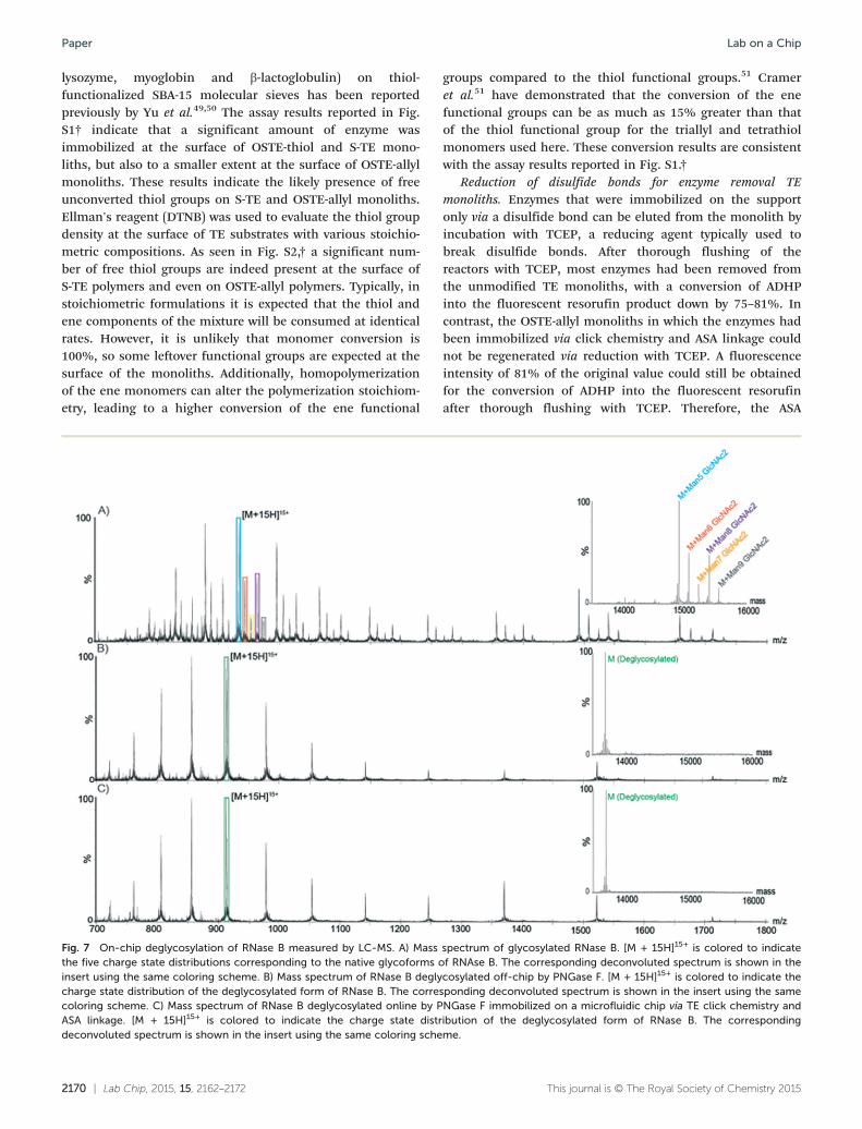
Fig. 7 On-chip deglycosylation of RNase B measured by LC-MS. A) Massthe five charge state distributions corresponding to the native glycoforms oinsert using the same coloring scheme. B) Mass spectrum of RNase B deglycharge state distribution of the deglycosylated form of RNase B. The correscoloring scheme. C) Mass spectrum of RNase B deglycosylated online by PASA linkage. [M + 15H]15+ is colored to indicate the charge state distrdeconvoluted spectrum is shown in the insert using the same coloring sche
groups compared to the thiol functional groups.51 Crameret al.51 have demonstrated that the conversion of the enefunctional groups can be as much as 15% greater than thatof the thiol functional group for the triallyl and tetrathiolmonomers used here. These conversion results are consistentwith the assay results reported in Fig. S1.†
Reduction of disulfide bonds for enzyme removal TEmonoliths. Enzymes that were immobilized on the supportonly via a disulfide bond can be eluted from the monolith byincubation with TCEP, a reducing agent typically used tobreak disulfide bonds. After thorough flushing of thereactors with TCEP, most enzymes had been removed fromthe unmodified TE monoliths, with a conversion of ADHPinto the fluorescent resorufin product down by 75–81%. Incontrast, the OSTE-allyl monoliths in which the enzymes hadbeen immobilized via click chemistry and ASA linkage couldnot be regenerated via reduction with TCEP. A fluorescenceintensity of 81% of the original value could still be obtainedfor the conversion of ADHP into the fluorescent resorufinafter thorough flushing with TCEP. Therefore, the ASA
This journal is © The Royal Society of Chemistry 2015
spectrum of glycosylated RNase B. [M + 15H]15+ is colored to indicatef RNAse B. The corresponding deconvoluted spectrum is shown in thecosylated off-chip by PNGase F. [M + 15H]15+ is colored to indicate theponding deconvoluted spectrum is shown in the insert using the sameNGase F immobilized on a microfluidic chip via TE click chemistry andibution of the deglycosylated form of RNase B. The correspondingme.

Lab on a Chip Paper
linkage provides a strong, irreversible covalent immobiliza-tion of the enzyme while immobilization via disulfide bondson unmodified TE monoliths featuring free thiol groupsallows for easy regeneration of the monoliths.
Storage stability of the galactose-oxidase enzymatic micro-reactor. Although enzymatic reactors featuring galactose oxi-dase immobilized via click chemistry and ASA linkage couldbe re-used immediately with minimal decrease in activity,even after thorough flushing with TCEP, enzyme activitydecreased significantly during storage as shown in Fig. S3.†Similar trends were observed both for never-used and re-usedenzymatic microreactors after up to 13 days of storage inDDW at 4 °C. Results indicate that optimally, the micro-reactors should be used within 4 days of their preparation.However, optimization of the storage conditions couldimprove the microreactor stability over time.
Deglycosylation of RNase B using the PNGase F enzymaticmicroreactor. PNGase F is a deglycosylation enzyme, whichcleaves N-linked carbohydrates. The activity of immobilizedPNGase F was assessed using RNase B as a substrate. RNaseB contains a single N-linked glycan at residue 60 and MSanalysis of a reference sample of native glycosylated RNAse Bshowed the presence of five high-mannose RNase B glycoforms(with a structure of two N-acetylglucosamines- and five to ninemannose monosaccharides). MS analysis of a reference sampleof RNase B deglycosylated off-chip showed a single mass at13692 Da, corresponding to the fully deglycosylated form ofthe protein. As shown in Fig. 7, RNase B samples processedwith PNGase F both on- and off-chip yielded similar spectra,corresponding to the fully deglycosylated protein and theabsence of any of the native glycoforms. Furthermore, similaron-chip deglycosylation was observed for chips employingeither strategy for PNGase F immobilization.
Conclusions
Thiol–ene microfluidic platforms featuring emulsion-templated porous monoliths show promise for applicationssuch as enzyme microreactors, where a large surface area isnecessary and it is paramount that the enzyme is stronglybound to the solid support. Highly uniform and monodis-perse bead-like thiol–ene monoliths were prepared insidemicrofluidic channels. Curing and anchoring inside themicrochannel was achieved in a single, rapid photoinitiatedstep without any prior surface modification. We have shownthat immobilization of enzymes on the prepared monolithsvia the formation of disulfides is straightforward and revers-ible. Alternatively, enzymes can be covalently and irreversiblyimmobilized via the free amino groups in their primary struc-ture by means of ASA linkage. The prepared galactose oxidaseand PNGase F microreactors demonstrated good enzymaticactivity in a galactose assay and the deglycosilation of RNaseB, respectively. The prepared monoliths also offer promise asstationary phases for on-chip separations thanks to their nar-row size distribution and the possibility to easily modify theirsurfaces with chemical groups for various retention modes.
This journal is © The Royal Society of Chemistry 2015
Acknowledgements
Funding for this project was provided by the Danish Councilfor Independent Research – Technology and Production(grant no DFF- 4005-00341). Author S.S. acknowledgesfunding from Denmark's Advanced Technology Foundation(grant no 144-2013-6). Authors J.N. and G.N. gratefullyacknowledge funding by the Erasmus program. Author J.N.acknowledges funding by the Grant Office project (GROFF,CZ.1.07/2.4.00/17.0106) and the Grant Agency of the CzechRepublic (project P20612G014). Author K.D.R. acknowledgefunding from the Marie Curie Actions Programme of the EU(grant no. PCIG09-GA-2011-294214) and the Danish Councilfor Independent Research – Natural Sciences (Steno Fellow-ship no. 11-104058). We acknowledge the Core Facilityfor Integrated Microscopy, Faculty of Health and MedicalSciences, University of Copenhagen as well as Dorthe Orbækfrom the Department of Pharmacy (University of Copenhagen)for her help with SEM imaging. Finally we would like to thankDenis Okhrimenko from the NanoGeoscience Center (Univer-sity of Copenhagen) for performing the surface area analyses.
References
1 J. Krenkova and F. Foret, Electrophoresis, 2004, 25,
3550–3563.2 F. Svec, Electrophoresis, 2006, 27, 947–961.
3 J. Krenkova and F. Svec, J. Sep. Sci., 2009, 32(5–6), 706–718. 4 F. Svec and A. A. Kurganov, J. Chromatogr. A, 2008, 1184, 281–295. 5 J. Krenkova, F. Foret and F. Svec, J. Sep. Sci., 2012, 35,1266–1283.6 F. Svec, J. Chromatogr., B, 2006, 841, 52–64.
7 S. Xie, R. W. Allington, J. M. J. Fréchet and F. Svec, Adv.Biochem. Eng./Biotechnol., 2002, 76, 87–125.8 H. Zhang and A. I. Cooper, Soft Matter, 2005, 1, 107.
9 M. S. Silverstein, Polymer, 2014, 55, 304–320.10 C. Harrison, J. T. Cabral, C. M. Stafford, A. Karim and E. J.
Amis, J. Micromech. Microeng., 2004, 14, 153–158.11 P. Wägli, A. Homsy and N. F. de Rooij, Sens. Actuators, B,
2011, 156, 994–1001.12 L.-H. Hung, R. Lin and A. P. Lee, Lab Chip, 2008, 8, 983.
13 B. Levaché, A. Azioune, M. Bourrel, V. Studer and D. Bartolo,Lab Chip, 2012, 12, 3028–3031.14 S. H. Kim, Y. Yang, M. Kim, S.‐W. Nam, K.‐M. Lee, N. Y.
Lee, Y. S. Kim and S. Park, Adv. Funct. Mater., 2007, 17,3493–3498.
15 E. P. Dupont, R. Luisier and M. A. M. Gijs, Microelectron.
Eng., 2010, 87, 1253–1255.16 S. Silvestrini, D. Ferraro, T. Tóth, M. Pierno, T. Carofiglio, G.
Mistura and M. Maggini, Lab Chip, 2012, 4041–4043.17 B. T. Good, S. Reddy, R. H. Davis and C. N. Bowman, Sens.
Actuators, B, 2007, 120, 473–480.18 V. S. Khire, Y. Yi, N. A. Clark and C. N. Bowman, Adv.
Mater., 2008, 20, 3308–3313.19 C. F. Carlborg, T. Haraldsson, K. Öberg, M. Malkoch and W.
van der Wijngaart, Lab Chip, 2011, 11, 3136–3147.Lab Chip, 2015, 15, 2162–2172 | 2171

Lab on a ChipPaper
20 J. P. Lafleur, R. Kwapiszewski, T. G. Jensen and J. P. Kutter,
Analyst, 2013, 138, 845–849.21 N. A. Feidenhans'l, J. P. Lafleur, T. G. Jensen and J. P.
Kutter, Electrophoresis, 2014, 35, 282–288.22 F. Saharil, C. F. Carlborg, T. Haraldsson and W. van der
Wijngaart, Lab Chip, 2012, 12, 3032.23 T. M. Sikanen, J. P. Lafleur, M.-E. Moilanen, G. Zhuang,
T. G. Jensen and J. P. Kutter, J. Micromech. Microeng.,2013, 23, 037002.24 C. E. Hoyle and C. N. Bowman, Angew. Chem., Int. Ed.,
2010, 49, 1540–1573.25 A. B. Lowe, Polym. Chem., 2010, 1, 17.
26 A. B. Lowe, C. E. Hoyle and C. N. Bowman, J. Mater. Chem.,2010, 20, 4745–4750.27 P. Thirumurugan, D. Matosiuk and K. Jozwiak, Chem. Rev.,
2013, 113(7), 4905–4979.28 Y.-X. Chen, G. Triola and H. Waldmann, Acc. Chem. Res.,
2011, 44, 762–773.29 P. Jonkheijm, D. Weinrich, M. Köhn, H. Engelkamp, P. C. M.
Christianen, J. Kuhlmann, J. C. Maan, D. Nüsse, H.Schroeder, R. Wacker, R. Breinbauer, C. M. Niemeyer and H.Waldmann, Angew. Chem., 2008, 120, 4421–4424.
30 V. Grazú, O. Abian, C. Mateo, F. Batista-Viera, R. Fernández-
Lafuente and J. M. Guisán, Biotechnol. Bioeng., 2005, 90,597–605.31 Y.-H. Rogers, P. Jiang-Baucom, Z.-J. Huang, V. Bogdanov, S.
Anderson and M. T. Boyce-Jacino, Anal. Biochem., 1999, 266,23–30.32 M. T. Neves-Petersen, T. Snabe, S. Klitgaard, M. Duroux and
S. B. Petersen, Protein Sci., 2006, 15, 343–351.33 W. W. Cleland, Biochemistry (Moscow), 1964, 3, 480–482.
34 E. Lovelady, S. D. Kimmins, J. Wu and N. R. Cameron,Polym. Chem., 2011, 2, 559–562.
2172 | Lab Chip, 2015, 15, 2162–2172
35 S. Caldwell, D. W. Johnson, M. P. Didsbury, B. A. Murray,
J. J. Wu, S. A. Przyborski and N. R. Cameron, Soft Matter,2012, 8, 10344.36 B. Sergent, M. Birot and H. Deleuze, React. Funct. Polym.,
2012, 72, 962–966.37 L. Kircher, P. Theato and N. R. Cameron, Polymer, 2013, 54,
1755–1761.38 C. R. Langford, D. W. Johnson and N. R. Cameron, Polym.
Chem., 2014, 5, 6200–6206.39 X. Gong, W. Wen and P. Sheng, Langmuir, 2009, 25,
7072–7077.40 R. A. Prasath, M. T. Gokmen, P. Espeel and F. E. D. Prez,
Polym. Chem., 2010, 1, 685–692.41 Z. Liu, J. Ou, H. Lin, Z. Liu, H. Wang, J. Dong and H. Zou,
Chem. Commun., 2014, 50, 9288–9290.42 Z. Liu, J. Ou, H. Lin, H. Wang, Z. Liu, J. Dong and H. Zou,
Anal. Chem., 2014, 86, 12334–12340.43 S. Brunauer, P. H. Emmett and E. Teller, J. Am. Chem. Soc.,
1938, 60, 309–319.44 G. L. Ellman, Arch. Biochem. Biophys., 1959, 82, 70–77.
45 P. W. Riddles, R. L. Blakeley and B. Zerner, in EnzymeStructure Part I, Academic Press, 1983, vol. 91, pp. 49–60.46 A. J. D. Magenau, J. W. Chan, C. E. Hoyle and R. F. Storey,
Polym. Chem., 2010, 1, 831.47 A. Patton and P. Chism, Anal. Chem., 1951, 23, 1683–1685.
48 J. Tiller, P. Berlin and D. Klemm, Biotechnol. Appl. Biochem.,1999, 30, 155–162.49 H. H. P. Yiu, C. H. Botting, N. P. Botting and P. A. Wright,
Phys. Chem. Chem. Phys., 2001, 3, 2983–2985.50 H. H. P. Yiu, P. A. Wright and N. P. Botting, J. Mol. Catal. B:
Enzym., 2001, 15, 81–92.51 N. B. Cramer and C. N. Bowman, J. Polym. Sci., Part A:
Polym. Chem., 2001, 39, 3311–3319.
This journal is © The Royal Society of Chemistry 2015