lace ad i ,on - welcome to nasa headquarters · lace ad .i aeronaz ministrat i .ctics ,on ... air...
TRANSCRIPT

Nutiona lace Ad
.I Aeronaz ministrat i
.ctics ,on
ET ESTIMATES
FISCAL YEAR 1974 Volume II
CONSTRUCTION OF FACILIXIE!i

NATIONAL AERONAUTICS AND SPACE ADMINISTRATION
CONSTRUCTION OF FACILITIES
FISCAL YEAR 1974 ESTIMATES
TABLE OF CONTENTS
VOLUME I1
General staternent ................................................ Appropriation language (proposed) ................................ Program and f inanc ing schedule ................................... Summary of cons t ruc t ion of f a c i l i t i e s budget p l an by
budget a c t i v i t y showing loca t ion t o t a l s included i n each a c t i v i t y ..................................................
*b
Summary of cons t ruc t ion of f a c i l i t i e s budget p l an by loca t ion .......................................................
Summary of cons t ruc t ion of f a c i l i t i e s p r o j e c t s by loca t ion ........................................................
Geographic l c c a t i o n of NASA I n s t a l l a t i o n s ......................... Capi ta l ized value of NASA’s f a c i l i t i e s ........................... J u s t i f i c a t i o r . by loca t ion :
Goddard Sps.ce F l i g h t Center , Greenbelt . Maryland ............... Je t PropulE. ion Laboratory. Pasadena. C a l i f o r n i a ................ Langley Resea.rch Center. Hampton. V i rg in i a ..................... Wallops Stati .on, Wallops I s land . V i rg in i a ...................... Various Loc:at.ions .............................................. Space S h u t t l e F a c i l i t i e s ....................................... Rehabi1itat:ion and Modif icat . ion ................................ Minor Consi.ruction ............................................. F a c i l i t y 1’:larming and Design ...................................
Page No . SUM 1
SUM 2
SUM 4
SUM 5
SUM 7
SUM 8
SUM 9
SUM 10
CF- 1 CF- 2 CF- 3 CF- 4 CF- 5 CF- h CF- 7 CF- 8 CF- 9
CF- i

NATIONAL AEXONAUTICS AND SPACE ADMINISTRATION
CONSTRUCTIOK OF FACILITIES
GENERAL STATEMENT
This appropr ia t ioc provides f o r con t r ac tua l s e r v i c e s f o r t h e design, m a j o r rehabi li t a t i on, and modif icat ion of f a c i l i t i e s ; t h e cons t iruct ion of new f a c i l i t i e s ; minor cons t ruc t ion ; t h e purchase of r e l a t e d equipment and advanced design r e l a t e d t o f a c i l i t i e s planned f o r f u t u r e au thor iza t ion . ‘Die p r i n c i p a l p r o j e c t s i n t h e 1974 program are descr ibed below:
MANNED SE’ACE FLIGHT: This a c t i v i t y inc ludes funds f o r space s h u t t l e f a c i l i t i e s a t var ious loca t ions . -I_--
---e SCIENTIF’1.C INVESTIGATIONS I N SPACE: This a c t i v i t y w i l l provide funds f o r t he r e h a b i l i t a t i o n of a v i b r a t i o n labora tory a t t h e Goddard Space F l i g h t Ck:nt.er, Greenbelt , Md. ; modif icat ions of and add i t ion t o t h e 25-foot space s imula tor bu i ld ing and modif icat ions of t h e p lane tary mission support f a c i l i t i e s at t h e Jet Propulsion Laboratory, Pasadena :, Cal i f .
SPACE AE’1’LI:CATIONS : This a c t i v i t y includes funds f o r t h e modif icat ion of a space 1aimc:h complex a t t h e Western T e s t Range, Vandenberg Air Fcrce Base, Ca:Lif . -.---
SPACE NU NUCLEAR RESEARCH AND TECHNOLOGY: No p ro jec t s f o r 1974. ---- AERONAUCICAL RESEARCH AND TECHNOLOGY: This a c t i v i t y inc ludes funding f o r t he r e h a b i l i t a t i o n and modi f ica t ion of t h e 600 p.s.i. a i r supply system ,st the Langley Research Center, Hampton, Va.
-----
---- SWPORTIXG ACTIVITIES: replacement of t h e t r a n s p o r t a t i o n f a c i l i t y a t tlie Goddard Space F l igh t
T h e estimates f o r t h i s a c t i v i t y provide f o r
Center; cons t ruc t ion of a sys t ems engineer ing bui ld ing a t t h e Langley Research Center; r e h a b i l i t a t i o n of a i r f i e l d pavement and a communication system a t t he Wallops S t a t i o n , Wallops I s l a n d , Va.; modif icat ion f o r f i r e p ro tec t ion improvements a t var ious t r ack ing and d a t a network s t a t i o n s ; modif icat ion of t h e power system a t t h e computer complex, S l i c i e l l , La. ; r e h a b i l i t a t i o n and modi f ica t ion of f a c i l i t i e s not i n excess of $500,000 pe r p ro jec t and minor cons t ruc t ion of new f a c i l i t i e s and. addi t ions to e x i s t i n g f a c i l i t i e s no t i n excess of $250,0t)O p e r p r o j e c t , a.t var ious NASA i n s t a l l a t i o n s and a t Government-owned p l a n t s , operated by con t r ac to r s ; and f a c i l i t y planning and design.
The appropr ia t ion f o r EY 1.973 w a s $77,300,000, t h e amount authorized i n The Authorizat ion A c t . The reques t f o r FY 1974 is $112,000,003, an increase of $34,700,000 from t h e FY 1.973 appropriat ion. $70,000,000 i n FY 1974, an i .ncrease of $16,000,000 from the $54,000,000 est imated €01: FY 1973.
Outlays are est imated t i : , be.
SUM 1

NATIONAL AERONAUTICS AND SPACE ADMINISTRATION
PROPOSED APPROPRIATION LANGUAGE
C ~ N S T R U C T I O N OF F.iCILrTIES
For advance planning, design, rehabilitation, modification and construction of facilities foi the National Aernniuticj and S , > x e Administration, and for the acquisition or condern?ntic)n o f red property, as authorized by law, C$77,300,000] $1 12,003,000, in- cluding [(l) $1,065,000 for rchabilitatinn and rn )dificztion of ieronautical, airborne science and support facilities, Arne3 Research Center; (2) $760,000 for rehabilitation of unitary plan wind tunnel model supports, control systems and rnodcl preparation areas, Ames Research Center; (3) $590,000 for rehabilitation and rn-jdifi- cation of utility systems, Goddard Space Flight Center; (4) $610,- 000 for rehabilitation and modiflcat.ion of roadway system, Jet Propulsion Laboratory; (5) $8,100,000 for modifications of, and additions to, spacecraft, assembly facilities, Kennedy Space Center; (6) $2,040,000 for modification of Titan Centaur facilities, Kennedy Space Center; (7) 82,465,000 for rehabilitation of full scale wind tunnel, Langley Research Center; (8) $1,175,OoO for modification of central air supply syst.em, Langley Research Center; (9) $6.50,000 for environmental modifications for utility operations, Langley Reaearch Center; (10) $9,710,000 for modification of high tempera- ture and high pressure turbine and combustor research facility, Lewis Research Center; (11) $585,000 for modification of fire pro- tection system, Manned Spacecraft Center; (12) $350,000 for ware- house replacement, Wallo s Station; (13) $6,800,000 for modifica- tion of altitud. test facifhes, Arnold En 'neering Development Center; (14) $1,160,000 for rehabilitation 3 propellant and high pressure gaseous systems, Mississippi Test F cility; (15) $1,635 000 or modification of entry structures facility, fiangley Research ken-
ter; (16) $2,545,000 for addition for system$integration and mockup laboratory, Manned Spacecraft Center; (17) $2,770,000 for mod% cation of vibration and acoustic test facility, Manned Spacecraft Cent t t ; (18) $4,700,000 for molification of structures and mechan- ics laboratory, Mamhall Space Flight Center; (19) $320,000 for addition for electrical power laboratory, Marshall Space Flignt CBnter; (20) $2,430,000 for modification of acoustic model engine test facility, Marshall Space Flight Center; (21) $5,540,000 for modification of manufacturing and final assembly facilities at un- designated locations] ( 1 ) $660, OOO for replacement of transgortataon .facility, Goddard Space Flight Center; (8) 871 0,000 for reha tlatataon of vibration laboratory, Goddard Space Flight Center; (3) $740,000 for modijicatwns of and adddion to 85-foot space simulator building, H . ,Allen Smith Jet Propulsion Laboratory; ( 4 ) $680,000 for modi$- cafzon of planetary mission support facilities, H . Allen Smith Jet Propulsion Laboratory; (6) $S,4l 0,000 for rehabildation and modi- $cation of 600 p.8. i . air supply system, Langley Research Center; (8) $1,880,000 for condruction of svstems engineering building, Langley Research Centimr; (7) $570,000 for rehabili!ation of airfield pavement, Wallops Statim; (8) $675,000 f o r rehabi1i:ation of com- munication system, Wallops Station; (9) $1,885,000 for modification for fire protection imprwcinenls at various tracking and data stations;
SUM 2

N I T IONAL AERONAUTICS AND SPACE ADMINISTRATION
PROPOSED APPROPRIATION LANGUAGE
CONSTRUCTION OF FACILITIES -Continued
( 1 0 ) $980,000 for modification of space launch complex 6 West, Vandenberg A i r Force Rase; (1 1 ) $1,085,000 for modification of power syr:t,em, Slidell Computer Complex; (16) $67,200,003 for Space Shuttle faczlities at various locations, as follous: ( A ) modifications foi auxil iary priipukion and power systems test facilities, White Sands Test Facility ( R ) modifications f o r Shuttle avionics integration laboratory, Manned Spacecraft Center, ( C ) modifications fo i radiant heating verijication facility, Manned Spacecraft Center, (D) modijcations for- the Orbiter propulsion system test facilities, Misbissippi Test Facili ty,(E) modi- fications f 31 external tank structural test facilitteC, - Marshall Space Flight Cenler, (f) modification of min!Ajac!urin7 and subassembly facil- itics for the Orbiter, N A S A Industrtal Plan:, Downey, Calif., ((;) modification of and addition to final assembly and chsckout facilities for the Orbiter, A i r Force Plant No. qS, Palmdale, Calif., ( H ) modification of manu acturing and final assembly facilities for ezternal t an t s , Michoul.4 ssembly Facility, ( I ) construclion of Orbiler landing facil i- ties, John F . Kennedy Space Center; r(22) 511,550,000~ ( f . ! ) $14,- 785,600 fo r minor rehabilitation and modification of facilities a t v a t h i s locatto.ir; C(2’3) %1,720,000] (14 ) $4,600,000 for minor con- struction of new facilititjs and aiditions to existing facilities a t vari- ouq locations; C(24) %8,000,000] (16) $1 3,600,000 for facility planning and design not cbtherwirc provided for ; to remain availzhle for obligation until Junr 30, C1975.l 1976: Provided, That, notwith- standing the limitations on the availability of f unds appropriated under this head hy this or the corresponding appropriation acts for the fiscal years 1973 (86 Stal. 644-646) and 1976 (86 Stat. 677) , and ezcept with respect to i t e m ( I S ) throuyh (16) above, items (62 ) through (24 ) of the cited fiscal yea1 1973 act, and the items for “rehcthilitation and modiji- cation of facilities” and “facility planning and design” of the cited fist:al year 1976 act, when a n y activity, for which appropriations under thiv head mctde by this or ths cited acts are available, has been initiated by the incurrence of obligations therefor, the amount available f o r such acrivity shall remain available until expended. (46 U.S.C. 6461, et seq.; Department of Housing and Urban Development; Space, Science, Veterans, and Certain Other Independent Agencies Appropriation Act, 1973; additional authorizing legislation to be proposed.)
sun 3

NATIONAL AERONAUTICS AND SPACE ADMINISTRATION
Identification code 27-oo-O 107-0- 1-250
& facilities actions proammed) - 1972 actual 1973 estimate 1874 estimate 1972 actual 1973 estimate 1974 estimate
Program by activities: I . Manned apace flight _ _ _ _ . ___.___.___.____.___.---...--..--.-
2. Scientific invertigationa in space ..___ - - - - - - - - -. - - - - - - - -. - - - - - 3. Space applications.-.. -. -. -. . - - -. - - - -. . - - -. . - - - - 4. Space and nuclear resurcli and technology.-. .___. .- _ _ _ _ _ _ .-- 5. Aeronautical research and technology ____..__ .. . ~. ~ ~ . - ~. . . . 6. Sumortinu activitiu. = ~ ~ ~ .. . . . . . . . ~. . ~. . . . -. ..__ ._ __. . -
- -. -. _.___.
18. 200 15.200
740 . ._.___. _.___
12,935 25.260
67.200 IO. 349 18.300 37,300 2.030 4,231 IO, OOO 6.600 980 3,585 600 800
I. I03 4M1 400 . . . . . . . 2.410 5: 662 10.700 7,500 39.380 21.674 17, ON 27,400
c___... ____ -- .. - 54,300 77.300 112.000 46.604 57. CO1 80,000
10 Total ______________.____.-------.----.----.-.-..-.------. 54.300 77.300 I 12.030 45.218 109, 600 I IO, 000
Total program coats, funded.-. -. . __. . -. . . -. . . . . . . . . -. . . -. 30. OOO --- -1,386 52,600 Change in ulected ruourcu 1 ___. -. _ _ -. _ _ _ -. . . - -. -. - - - _ _ _ _ _ - - _ _ _ _ - _._ _ _ _ - - - _ _ _ - -_. - - -. .--. ____ -__ ~-
Fmmcing: 21 Unobligated balance available. atart of year, for completion of prior
-53.1 IO -63.197 -32.297
200 _ _ _ _ _ _ _ _ _ _ _ _ __________._ _ _ _ _ _ _ _ _ _ _ _ _ - - _ _ _ _ _ _ _ _ _ - - _ - - - - - - - - --. 34.297
year budget plana. - ~ - - - ~. ~ - _..__ _ _ - .~ - - _ _ _ - _ _ - - - _ _ . - _ _ _ _ - _ _ _ _ _ - _ - _ _ _ - - - - - - - 22 Unobligated balance transferred from other accounts. -. _ _ .. . - -. - -1.400 _ _ _ _ _ _ ~ - - _ _ _ -._..-- -.--- -2,605 -1.400 - _ _ _ _ _ - _ - _ - - - - Reprograming from prior year budget plans . . -. -. . -. . - -. . -
Unobligated hlance available, end of year, for completion of prior year budget plana-- - _ _ ~ -. -. - -. -. . -. .- -. ~. - -. _ _ - _ _ ~ ~ _ _ - _ _ _ _ _ _ _ _ _ _ _ _
24 - 63,197 32.297
. -- _____- 40 Budget authority (appropriation) - --. -. -. . - -. . - - -. - - - - -. - - - 52,700 77,300 112, OOO st, 700 77,300 112, ow
I Selected resources a, of June 30 are as follow,: Undelivered orders. 1971. $32.271 thousand; 1972. $30.885
1971 1973 d u d r r l l n d s u l l n a l r
Note.-Reconciliation of budle t plan to oblisations: 77,300 112,000 Total budie t d a n . . ..__. ...____ _ _ _ _ _ _ _ ~ -. _._ _ _ _ _ _ _ _ _ ~ _ _ _ 54.300
I974 thouland: 1973. $83.485 thourand; 1974. $1 13.485 thousand.
31 220 29: 220
Deduct -portiLn of - b i d g e t - plan to be obligated in subsequent *j;ar,-- _______..__.__ _.___..___.__________________ ~ _ _ _ _ _ _ _ 36 397 18,700
obligations of prior year budle t plans-.. _ _ _ _ _ _ _ _ _ _ _ _ _ _ _ _ _ _ 27:815 51,000 - -- Total obligations _ _ _ _ _ _ _ _ _ _ _ _ _ _ _ _ _ _ _ _ _ _ _ _ _ _ _ _ _ _ _ _ _ _ _ _ _ _ _ 45,218 109,600 110,000

NATIONAL AERONAUTICS AND SPACE ADMINISTRATION
F I S C A L YEAR 1974 ESTIMATES
SUMMARY OF CONSTRUCTION O F F A C I L I T I E S BUDGET PLAN_ ---- BY BUDGET A C T I V I T Y SHOWING LOCATION TOTALS INCLUDED I N EACH ACTIVITY_
Fiscal Y e a r Fiscal Y e a r F i sca l Y e a r 1972 1973 1974 __
1. MANNED SIPACE FLIGHT. . .......... $18,500,000 $ 2 7 , ~ ~ 0 ~ 0 0 0 $67,200,00!?
Space S h u t t l e f a c i l i t i e s a t 1~ai:ious loca t ions . . ..... 18,500,000 27,900,000 67,200,000
2. SC1:ENTI:FIC: I N V E S T I G A T I O N S I N SPACE:. .................... $15,200,000 $11 . 205 . 000 $2 . O3O3OC!0
- - - 1 , 065 , 000 --- l i m e s R e s e a r c h C e n t e r . . ....... --- - - - 7 10 , 000 G o d d a r d Space F l i g h t C e n t e r . . ,Jet Propuls ion Laboratory.. .. --- - - - 1 , 320,000
.John I?. K e n n e d y Space
V a r i o i i s Locations. . .......... - - -
C e n ~ e r , NASA... . . . . . . . . . . . . ~ 5 , 2 0 0 , 0 0 0 10,14Oy00O --.- - - - ---
3 . SPACE fL2P1; I C A T I O N S ............. $740,000
G o d d a r d Space F l i g h t C e n t e r . . 740,000 'JarioJs Locations. . .......... ---
$980 , OC,O
4. SPACE A a D NLTCLEAR RESEARCH -. - ~ _ _ _ _ _ --- - - - AND 'TECHNOLOGY. .............. 5. AERONAlJTICAL RESEARCH
AND 'TEC'HNOLOGY. .............. $7 , 3 60 , 0 00 $12 , 9 3 5 , OOC! $2 , 4 10 , 00 0
7 60 , 000 A m e s R e s e a r c h C e n t e r . . . . . . . . . 6 , 500,000 L a n g l e y R e s e a r c h C e n t e r . . . . . . - - - 2,465,000 2 , 4 1 0,000 L e w i s R e s e a r c h C e n t e r . . . . . . . . 860,000 9,710,000
- ._ -
- ._ -
SUM 5

6. SUPP0RTI:NG ACTIVITIES
Gocltfard Space F l i g h t Center. . Jet: Propulsion Laboratory.. .. Langley Research Center.. .... Mariiietl Spacecraf t Center.. ... Wa1.I op s S t a t ion. ............. Var:ious Locations. ........... Rehabi l i ta t ion and
Modification.. ............. Minor Construct ion. .......... Fac:il i ty Planning and Design.
Total Pla.rt . .........................
F i s c a l Year 1972
$12,500,000
1,100,000
7,900,000
3,500,000
$54.300.000
F i s c a l Year 1973 -
$25,260,000
590,000 610,000
1,825,000 585,000 350,000 - - -
11,580,000 1,720,000 8,000,000
F i s c a l Year 1974-
$39,380,000
660,000
1,620,000
1,145,000 2,970,000
- - - .- - -
14,785,000 4,600,000
13 , 600 ,e $77.300.000 $112,000,000 - -
SUM 6

NATIONAL AERONAUTICS AND SPACE ADMINISTRATION
FISCAL YEAR 1974 ESTIMATES
--- SUMNARY OF CONSTRUCTION OF FACILITIES BUDGET PLAN BY LOCATION
Locztion ---- Ames Research Center............... Goddard Space F l i g h t Center.. . . . . . . Jet Propulsion Laboratory .......... John F. Kennedy Space Center , NASA. Langley Research Center.. .......... L e w i s Research Center.. . . . . . . . . . . . . Manned Spacec r a f t Center.. ......... Wallops Stat ion. . . . . . . . . . . . . . . . . . . . Various Locations... . . . . . . . . . . . . . . . Space Stiu t t 1 e F a c i l i t ies ........... Rehab i l i t a t ion and Modification.. .. Minor Construct ion.. ............... F a c i l i t y Planning and Design. ......
Tota l Plac ........................
F i s c a l Year 1972
$6,500,000 $740 , 000
15,200,000
860 , 000
- - -
- - -
--- - - -
1 , 100,000 18,500,000
7 , 900,000
3 , 500 , 000 - - -
$54,300,000
F i s c a l Year 1973
$1,825,000 $590,000
610 , 000 10,140,000 4 , 290 , 000 9,710,000
585 , 000 350 , 000
27,900,000 11,580,000 1 , 720,000 8 , 000 , 000
- - -
F i s c a l Year 1974-
- - - $1,370,000 1 , 320,000
4,030,000 - - -
- -- - - -
1,145,000 3 , 950 000
67,200,000 14,785,000 4 , 600 000
13 , 600,000.
$77,300,000 $112,000,000~
SUM 7

NATIONAL AERONAUTICS AND SPACE ADMINISTRATION
FISCAL YEAR 1974 ESTIMATES
--- SUMMARY OF CONSTRUCTION OF FACILITIES PROJECTS BY L O C A T C
Fiscal Year 1974
Goddard Space Flight Center.................................. $1,370,000
Replacement of transportation facility ..................... Rehabilitation of vibration laboratory .....................
660,000 7 10,000
Jet Propulsion Laboratory.................................... 1 320 000
Modifications of and addition to 25-foot space
Modification of planetary mission support facilities. ...... simulator building ....................................... 740,000
580,000
Langley Resea.rch Center....,.................,............... 4,030,000,
Rehabili.t:at ion and modification of 600 psi air supply
Construction of systems engineering building ............... syste~i.... ............................................... 2,410,000
1,620,000
Wallops St:nti.on...... ........................................ 1,145 OOC!
Rehabilj.i:at:ion of airfield pavement ........................ Rehabilitation of communication system.. ...................
570,000 57 5,000
Various Locat: ions. ........................................... 3,950 000 ---_- Modifical-ion of power system., ............................. Modification of space launch complex 2 west (SLC-2W) ....... Modtfication for fire protection improvements..............
1 085 000 980 000
1,885,000
Space Shuttle Facilities..................................... 67,200,00(~.
Rehabilitiztion and Modification.............................. 14,785,00(2
Minor Construction........................................... 4,60OY00(l - --_-- Facility Planning and Design.. ............................... 13,600,ooO
Total Plan.. ............................................. - $112,000,000 --
SUM 8 491-31 I C) - 73 . !

LOCATION OF NASA MAJOR AND COMPONENT INSTALLATIONS
AEC-NASA SNSO KSC WESTERN TEST RANGE OPERATIONS
DARD SPACE NASA PASADENA FLIGHT CENTER (GSFC)
WALLOPS STATION WS) JET PROPULSION LABORATORY 0 PL) (C 0 NTRACTOR
DQUARTERS, D c
RESEARCH CENTER (LaRC)
FLIGHT RESEARCH / I SPACECRAFT / / \ \ KENNEDY SPACE CENTER (KSC)
MARSHALL SPACE
CENTER (FRC)
. MISSISSIPPI TEST FACILITY
COMPUTER / (MSFC)
MSC WHITE SANDS TEST FACILITY W W MICHOUD
ASSEMB LY

RECORDED VALUE OF CAPITAL TYPE PROPERTY (IN-HOUSE AND CONTFACTOR-HELD)
AS OF JUNE 30, 1972 (DOLLARS IN THOUSANDS)
_- R a l Property
G lend Fixed Assets Other StNCtunS Leouhold -
Reporting lnshdzl Land Buildings o d Focilitier lrnpmvemenh T o b l Equipment 2/ in Progress TO<
OFFICE OF MANNED SPACE FLIGHT
K m d y Space Center KSC - Florid0 Western Tart Ronge Operations Division
Lmpoc, Gli fornio Various Locmtionr 1/
Manned Spacecroft Cent0 MSC - Houston, Texxos Whits b n d i last Facil ty
WSTF - Lis CNCOS, Idav IMexico Various Locotions 1/
ManhoII Space Flight Cerster MSFC - Huntsville, .Alabami Michoud Arvmbly Fcic l i ty
MAF - New Orlmns, Lou siona Mississippi Test Focilit,
MTF - b y St. Louis, Mississippi Slidell Cmipvter Foci1 ty
SCF - Slidell, Louiiiirm Voriovl Locations 1/
OFFICE OF AERONAUTICS AND SPACE TECHNOLOGY
Amas Reseorch Center ARC - Moffdt Field, (2difwnia Various Locations 1/
FRC - E d w d r , b l i i o - n m Variou Locotiom y
Longly Rerarch Center LaRC - Hempton, Virp nia Various Locations 1/
F l i h t R-rch Center
Lewis Re-rch Center LeRC -Cleveland, Ohio Plum 8 4 Sfotion
PBS - Sandusky, Oii,, Various Locotions 1/
Space Nuclear Systems 0:fics
Various Locations I/
Various Locations !/ OFFICE OF SPACE SCIENCE
SNSO/N - NRDS - bckarr Flats, N e v d a
SNSO/G - Ge-nbn, Evarylond
Goddord Space Flight Center GSFC - Greenbelt, Mirylod Tracking Smtions (Gcl . DSN) ?/ Various Locations 1/
JPL - California Tmsking Smtiom (D:IFI) :/
WS - Wollop Island, Virginia Voriorn Locotions 1/
Jet Propulsion Loborotoiy
Wallop Station
OTHER - NASA Hmdqwrtsn
Washingtors, DC Various Locations 1,'
G W N D TOTAL
$107,471 $ 753.700 $ 703.537 $3,607 $I ,W,315$1,743,67 '3 $ 3 1 . W $3,343,669
72,171 286,274 350,028 708,473 588,963 13,352 1,3 IO, 793 72,171 286.274 350,028 708,473 175,745 9,038 -esw -
6,351 4,314 10.665 405,871 4M. 87 1
9.029 178.011 52,859 239.899 622, I32 12,334 874.365 5,459 12.334 T m 144,298 30, w 3 180,nO 293,673
8,691 16,855 25.546 35,395 60,941 3,570 25,022 5,Ml 33,633 293,059 396,692
26,271 289,415 300,650 3,607 619,943 532,575 5.998 1,158.51 1 112,838 51.058 164,696 245.445 782 -41-
7,505 64,168 25.936 97,609 60,503 129 ISH.241
18,703 81,649 185,435 285,787 34,199 2,544 3i2,530
63 4,481 879 5,423 20,215 15.639 26,279 36,542 3,607 66,428 172,205 543 239, ITt
1,250,330 6,181 526,872 225,692 139
2,373 176,188 3,WZ 182,523 87,432 10.609 280,564 2,373 176,063 3,%2 182,398 83 ,767 10,609 -17-
125 125 3.665 3,790
5 9 . m 514 _-__ 8,479 2,629 11,108 47,477 8,479 2,525 11.004 43,591 514 55,109
1M I O 4 3,885 3,990
758 ,W 440,897 50,549 -
-
116 125,024 149,007 274,14/ 138,525 15,527 428, I 9 9 1 IO 109,620 148,982 258.712 124,022 15,527 -
6 15,404 25 15,435 14,503
428,560 265.188 139,473 23,894 328 114,220 41,294 139 23,890 253,112 155,981 73,241
3,692 198,193 63,164 139
3,285 80,922 18,221 102,428 13,269 4 115,701 79 3,051 3,649 6,779 52.963 59,747
18,988 6,930 25,918 27,98- 5 53,963 25,918 4,304 5 -7w
6,821 h,821 18,988 6,930
16,863 10,860
3,797 173,843 142,553 546 320,739 763,4883- 49,889 1.134.1 I6
1,647 91,628 64,147 81 157,503 521,943 11,149 690, M) I
361,267 1.308 73,732 14,729 89, 050 171,362 11.149 - 7 m 81
67,520 293,747 339 17,808 49,373 88 45 133 56,845 56,973
1.067 59,887 33,343 465 94,762 192,777 36,740 324,27'?
lC'5.314 1.067 50,279 8.048 465 59,059 122,355
1,083 22,328 45,063 68,474 48,762 2.000 11Y,236 22,328 45,063 ,525 2,000 -----i-iw
233 1.083
a3 83 21,405 11,489
iI.489 a3 83 21,405- 1 1 3,172 3,173
82 82 18,234 1H.316
36,740 -nm 34,903 70,411 9.608 25,295
68.474 48 23 3
- -
I 117,449 $ 1,454,415 I1,071,782 $4,375 $2,648,021 $2,969,461 I 132,122 $5,74V.604 ~ ____-
I/ z/ ?/
lnc l des mfopitol Type Property in Possession of Contmcton at Various Locations. lncl d e s 'fontroctor-Held Special Test Equipment (1744,136K). D5N - D*sep Space ktvoh.
SUM 10

NATIONAL AERONAUTICS AND SPACE ADMINISTRATION
CONSTRUCTION OF FACILITIES
FISCAL YEAR 1974 ESTIMATES
GODDARD SPACE FLIGHT CENTER
Page No.
Location p l .an................................................... CF 1-1
Summary ......................................................... CF 1 - 2
Off ice of S8pac:e Science P r o j e c t s :
Replacement of Transportat ion Fac i l i t y . . ...................... Rehabilit:atj.on of Vibrat ion Laboratory.. ......................
CF 1-3
CF 1-7
CF 1


NATIONAL AERONAUTICS AND SPACE ADMINISTRATION
INSTAL4ATION SUMMARY CONSTRUCTION OF FACILITIES
FISCAL YEAR 1 9 7 4 BUDGET ESTIMATES
( D o l l a r s in thousands) _-_~____------- -___
COGNIZANT PROGRAM O F F I C E FOR IN'jTALLATlON - NASA INSTALLATION
--__ Goddard Space Flight Center
Greenbelt, Maryland
The Center is responsible for complete development of unmanned sounding rockets and orbiting :~l~ac:ecraft experiments in basic and applied science. scientific satell.ites, and communications and weather satellites which orbit in cislunar space (region between the earth and moon). NASA's Delta launch vehicle project and two worldwide tracking, data acquisition
Space Science NEAREST C I T Y T_----- Greenbelt, Maryland .-__
LOCATION OF INSTlrL.LATION
--- INSTALLATICIN MISSION
The work covers
In addition, the Center manages
660 I 65 I
and data reduction networks.
43 1
COG N I Z ANT PROJECT L I N E ITEM OFFICE
- -_- Replacement of transportation facility
Rehabilitation oE vibration laboratory
-__ NASA FORM 1029 JUN (69 PREVIOUS EDITIONS ARE OBSOLETE.
I t - - 7 10
1,370
-0-
-0-
TOTAL ALL 'EeritnateaO YEARS
__----
7 2 5
753
1
NASA-HQ CF 1 - 2

CONSTRUCTION OF FACILITIES
FISCAL YEAR 1974 ESTIMATES
Replacement of Transpor ta t ion F a c i l i t y
LOCATION Goddard Space F l i g h t Center
FY 1974 CoF ESTIMATE $660,000
COGNIZANT INS'J'ALLATION: - Goddard Space F l i g h t Center
LOCATION ---- OF PROJECT: Greenbelt, Pr ince George's County, Maryland
COGNIZANT PROGRAM -- OFFICE: Off ice of Space Science
FY 1973 AND P R G R YEARS CoF FUNDING:
Planning and Design Cons t r u c t io r .
$65,200 - -- * Total FY 1973 and P r io r Years $65,200
*No Constructi.on of F a c i l i t i e s funds have been appl ied t o t h e e x i s t i n g f a c i l i t y s ince t r a n s f e r t o NASA from DOD.
SUMMARY PURPCI~~AND SCOPE:
The purpose of t h i s p ro jec t i s t o provide a new f a c i l i t y t o r ep lace the e x i s t i n g Transportat ion F a c i l i t y . A s i n g l e s t o r y s t r u c t u r e of approximately 14,000 square f e e t i s proposed. The new f a c i l i t y w i l l service t h e assigned motor vehicles and t h e Center ' s e l e c t r o n i c equipment vans. The e x i s t i n g f a c i l i t y has rumerous d e f i c i e n c i e s which r e s u l t i n a t o t a l l y inadequate and i n f e r i o r f a c i l i t y .
PRO J E C T JUS T I E ' I C AT1 ON :
The f a c i l i t j p a t t h e Goddard Space F l i g h t Center c o n s i s t s of a shop f o r r e p a i r , maintenance, and opera t ion of e l e c t r o n i c equipment vans and motor vehic les , plus, r e l a t e d admin i s t r a t ive o f f i ces .
The e x i s t i n g f a c i l i t y i s a temporary bui ld ing f o r which a replacement i s required. There are t h r e e bas i c condi t ions which j u s t i f y replacement:
1. Serious de t e r io ra t ion .
2. F a c i l i t y l i m i t a t i o n s preclude e f f i c i e n t performance of ass igned act i v i t i.es .
3 . Substandard working condi t ions which con t r ibu te t o undes i rab le hea l th and safet .y en.x5ronment.
CF 1 - 3

D e t e r i o r a t i 3n :
The insu la t ion , metal "skin", roof and o the r por t ions of t he bui ld ing have, d e t e r i o r a t e d t o such an ex ten t t h a t , based on a recent survey, t he est imated c o s t of needed b a s i c r e p a i r s was approximately $320,000. This i s almost ha l f t he c o s t of t he proposed p ro jec t . Further , th i s , expendi- t u r e would not so lve the o the r problems l i s t e d .
F a c i l i t y L:ini ta t ions :
This f a c i l i t y c u r r e n t l y services 110 t ra i le r vans, 10 t r a c t o r s , 100 t rucks , 50 passenger automobiles, cranes and o the r miscellaneous wheeled equipment. by the cu r ren t f a c i l i t y and i t s present loca t ion :
The following l i s t i d e n t i f i e s some of t h e l i m i t a t i o n s imposed
1. k e maintenance bays are too s m a l l t o accommodate t h e e l e c t r o n i c vans. Thus, they must be cleaned and serv iced ou t s ide t h e bui lding.
2. r e s u l t s i n an i n e f f i c i e n t and marginal ly s a f e type of maintenance and r e p a i r a c t i v i t y .
InsuEf ic ien t head room p r o h i b i t s proper use of t ruck l i f t s . This
3. her , . i s inadequate room t o maneuver t h e l a r g e t r a c t o r - t r a i l e r u n i t s used f 'or long d i s t ance hauling.
4. I'here i s i n s u f f i c i e n t e l e c t r i c a l power de l ivered t o t h e f a c i l i t y t o opera te a l l of t h e requi red equipment.
Substandard Conditions:
1. Provision f o r quick drenching of t h e eyes and body f o r "emergency use" i s no t ava i lab le .
2. Ins ide (storage area has no s p r i n k l e r system and has no di . rec t egress t o t h e ou t s ide i n case of f i r e .
3 . ' h e 'lunch room i s loca ted next t o the s a n i t a r y f a c i l i t i e s which need t o be replaced.
4 . ' fie lack of s a n i t a r y f a c i l i t i e s f o r women.
5. 'Vent.ilation in t he b a t t e r y room, shop areas and d i spa tche r ' s o f f i c e i s inadequate.
6. 'The indiv idua l o i l f i r e d h e a t e r s do not provide adequate hea t ing , bu t do con t r ibu te t o a i r polutiori.
7 . Water drainage problems exis t which tend t o c r e a t e a damp working environment i n the present area as w e l l as t o a c c e l e r a t e t he r a . t e of de t e r - i o r a t i o n oE t he m e t a l bu i ld ing skin.
CF 1 . 4

PROJECT DESCRIPTION:
The proposed facility will be a one story structure approximately 10,000 square feet in area with a partial mezzanine of an additional 4,000 square feet. Length will be 1 3 1 feet and the maximum width 78 feet.
It is planned that the structure will be a continuously welded exposed steel frame with a reinforced concrete floor slab and a lightweight insulated roof deck over long-span open-web steel joists. The exterior walls will be precast tilt-up concrete panels of color and texture to harmonize with other structures in the Center. Existing utility and road systems will be extended to the facility.
PROJECT COST ESTIMATE: ----
Unit of Unit Total Measure Quan t i t y cost cost
--- --- -e- --- Land Acquisition --
Site Preparation -- LS --- $135,700
--- Utilities LS . - - 119,300
Construction Architectural structural SF
356 000 14,000 $13.55 189,700
Mechanical plumbing, heating and ventilating SF 14,000 3.69 51,700
Air conditioning SF 8,000 4.62 37 000 Electrical SF 14,000 3.08 43,100 Fire protection SF 14,000 2.46 34,500
Fixed Equipment -- -- 49 000
--- --- --- - - - Fallout Shelter (Not Feasible)
TOTAL
FUTURE CoF ES’IIIMAATED -- FUNDING REQUIRED TO COMPLETE THIS PROJECT:
$660,000
For presently planned usage there are no currently foreseen future funding requirements necessary to complete this project.
CF 1-5 49-315 0 - 73 - 3

'9-
,.
,

CONS TRUC T I OM OF FAC I L I T I E S
FISCAL YEAR 1974 ESTIMATES
---I --
PROJECT TITLS Rehab i l i t a t ion of Vibrat ion Laboratory _-
LOCATION Goddard Space F l igh t Center ---
- FY 1974 CoF ESTIMATE $710,000 _- ----
COGNIZANT --- :CYSTALLATION: Goddard Space F l igh t Center
LOCATION ---- OF PROJECT: Greenbelt, Pr ince George' s County, Maryland
COGNIZANT 13C3RAM OFFICE: Off ice of Space Science
FY 197:3 --- ANI) PRIOR YEARS CoF FUNDING:
Planning m d Design Construct ion
$42 , 600 -I<
Total 17.f :-973 and P r io r Years $42.600
*The exi;t:-ng appl icable equipment w a s included with the cons t ruc t ion of the orf-ginal bu i ld ing ( the Payload Test F a c i l i t y , Building #7, a t GSFC) and i s not s epa ra t e ly i d e n t i f i a b l e .
SUMMARY PUE::?OSE AND SCOPE: --I
This pro:icxt: provides f o r t he r e h a b i l i t a t i o n of t h e v i b r a t i o n labora tory of t he Pay1.oacl Test F a c i l i t y , Building #7, t o meet t h e demands of advances i n technology and the more soph i s t i ca t ed t e s t requirements of complex cur ren t and f u t u r e spacecraf t . Spec i f i ca l ly , t h i s p r o j e c t w i l l r ep l ace each of the two 10,,000 pound fo rce e x c i t e r systems with a 17,500 pound force system. It will a l s o provide f o r r e h a b i l i t a t i n g and upgrading t h e e x i s t i n g 28,000 pound fo rce sys t en t:o a 35,000 pound fo rce system.
PROJECT J U S ~ ? I I ' I C A T I O N : ---
F l i g h t hsu-dware must undergo v i b r a t i o n t e s t i n g t o determine i t s a b i l i t y t o withstand the launch and p r e o r b i t v i b r a t i o n environment. Over the l i f e of t he space program, NASA has instrumented spacec ra f t and launch veh ic l e s t.o detemi.ne t h i s a c t u a l environment: and t o relate these a c t u a l f l i g h t d a t a t o the t e s t i n g program. With approximately $50,000,000 of f l i g h t hardware being t e s t e d i n the v i b r a t i o n l abora to ry each year , i t i s of paramount importance t h a t a l l of t k e v i b r a t i o n systems perform r e l i a b l y and e f f ec t iv ' s ly during t e s t .
CF 1-7

New test parameters r e c e n t l y have placed more s t r i n g e n t requirements on t h i s equipment. The f i r s t of t hese parameters i s the p r o t o f l i g h t concept which decreases t h e o v e r a l l program c o s t , bu t d i c t a t e s g r e a t e r r e l i a b i l i t y i n the e x i s t i n g systems. The second i s t h e performance of shock t e s t i n g on the v i b r a t i o n systems which allows more r e a l i s t i c t e s t i n g t o be performed, bu t adds g r e a t l y t o the mechanical stresses on t h e equipment. The t h i r d test i s the workmanship v i b r a t i o n test which i s performed s h o r t l y before a space- c r a f t launch, Any delay i n t h i s test i s d i r e c t l y t r a n s l a t e d t o the launch d a t e and add:; s i g n i f i c a n t l y t o the c o s t of t he program.
With these newer condi t ions being imposed, t h e r e i s a cont inuing concern f o r t he :safety of t he f l i g h t hardware being t e s t e d on these older and very obsole te system:;. A l l major elements of t hese e x i s t i n g systems are over t e n years old. (hmponents of t h e systems are f a i l i n g because of high vo l t age breakdown antl mechanical f a t igue , thus sub jec t ing f l i g h t hardware t o unwanted t r a n s i e n t v i b r a t i o n s which can have damaging e f f e c t s on t h e i t e m being tes ted. ,
Precaut ions such as the i n s t a l l a t i o n of p r o t e c t i v e devices and the imple- mentation of exitensive opera t ing and maintenance procedures have been taken which have resu' l ted i n de lays t o t e s t i n g programs and have not e l iminated the cont inuing :random f a i l u r e s .
Maintenance now requ i r e s about 45% of the working hours and t h i s percentage i s increasing. Replacement p a r t s are no t ava i l ab le , f a i l e d p a r t s must be r e b u i l t a t t h e Eactory and, i n some cases dera ted , causing the equipment t o have less c a p a b i l i t y than when o r i g i n a l l y i n s t a l l e d .
With the inlzreased s i z e and weight of spacec ra f t , t he 10,000 pound fo rce e x c i t e r s c a n m t handle many of t h e l a r g e r test i t e m s which i n tu rn increases the work load on the l a r g e r 28,000 pound f o r c e system. Addi t iona l ly , a l l of t he e x i s t i n g exci ters have a suspension system which induces unwanted v i b r a t i o n input:; t o t h e t es t i t e m s .
A d e t a i l e d <cost e f f ec t iveness s tudy showed t h a t t he modernization of t he v i b r a t i o n l a b m e t o r y w i l l pay f o r i t s e l f w i th in a r e l a t i v e l y s h o r t per iod i n manpower :;avings and w i l l a l low more tests t o be made wi th a . l esser equip- ment inventory.
PROJECT DESCli IP'IIION: ---- The plan f o r modernization of the v i b r a t i o n l abora to ry includes rep lac ing
some e x i s t i n g equipment and overhauling t h e balance of t h e e x i s t i n g systems. It w i l l be aczomplished i n two phases i n order t o minimize exc i te r -sys tem down t i m e . A typical v i b r a t i o n system c o n s i s t s of one o r more exciters, an ampl i f i e r antl a con t ro l console. The con t ro l console synthesizes t h e requi red shock o r vib:rst ion d a t a and feeds i t t o the ampl i f i e r where i t i s amplif ied e l e c t r i c a l l y . 'L'his e l e c t r i c a l s i g n a l i s fed t o t h e exciter which transforms the s i g n a l i n t o a des i r ed mechanical e x c i t a t i o n which v i b r a t e s or shocks t h e spacec ra f t being tes ted .
CF 1-8

I n Phase I it i s planned t h a t t h e two 17,500 pound f o r c e exciters, with improved suspension systems w i l l r ep l ace two 10,000 pound f o r c e exciters, t h e high vol tage power ampl i f i e r w i l l be replaced by a low vo l t age s o l i d s ta te ampl i f i e r and t h e v i b r a t i o n console w i l l be replaced by a d i g i t a l con t ro l console. I n add i t ion , t h e backup 10,000 pound fo rce system cons i s t - i ng of two e x c i t e r s and high vo l t age ampl i f i e r , and one c o n t r o l console w i l l be surplused a f t e r t he new system i s accepted and becomes opera t iona l .
I n Phase I1 i t i s planned t h a t t he p re sen t 28,000 pound fo rce exciter w i l l be upgraded t o 35,000 pound fo rce , t he high vo l t age power ampl i f i e r w i l l be replaced w i t ' h t h e low vo l t age s o l i d s ta te ampl i f i e r and t h e v i b r a t i o n console replaced with a d i g i t a l console.
Along with the new v i b r a t i o n equipment being i n s t a l l e d , i t i s planned t o remove the w a l l between the two e x i s t i n g 10,000 pound e x c i t e r ce l l s , modify the two e x i s t i n g seismic blocks, remove t h e two steel s ta i rways , and connect t he monorail i n each cel l . The e x i s t i n g e lectr ical se rv ices f o r t he equip- ment w i l l be modified as necessary by reworking the electrical connections i n t h e immediate v i c i n i t y of t he new equipment.
PROJECT COST ESTIMATE: ----
Land A c q u i s --- i t ion
Construct ion
Arch i t ec tu ra l and s t r u c t u r a l E l e c t r i c a l Mechanical Equipment i n s t a l l a t i o n
Equipment
Control consoles Power ampl i f i e r (17,500) Power ampl i f i e r (35,000) 17,500 pound fo rce exci ter Rebuild and upgrade 28,000
pound f'orce exciter
----- Fa l lou t S h e l t e r (Not Applicable)
Unit of M e as u r e
- - -
LS LS LS LS
Each Each Each Each
Each
To ta l c o s t
- - - $60,000
25,000 3,000 12,000 20,000
650,000
304,000 74,000 142,000 92,000
38,000
--- $710,000
CF 1-9

A t t h i s time no o the r equipment i t e m s have been i d e n t i f i e d as being requi red f o r t he in i t i a l . opera t ion o r use of t h i s f a c i l i t y .
FUTURE CoF E!C!T:CMATED FUNDING REQUIRED TO COMPLETE THIS PROJECT:
For p re sen t ly planned usage t h e r e are no c u r r e n t l y foreseen f u t u r e funding requirement:; necessary t o complete t h i s p ro jec t .
CF 1-10

GODDARD SPACE FLIGHT CENTER
FISCAL YEAR 1974 ESTIMATES
REHAB! L!TAT!ON OF V I BRATION LABORATORY

NATIONAL AERONAUTICS AND SPACE ADMINISTRATION
CONSTRUCTION OF FACILITIES
FISCAL YEAR 1974 ESTIMATES
JET PROPULSION LABOMTORY
Page Na.
Location plan ................................................... CF 2-1
Su~ry..... .................................................... CF 2-2
Office of Space Science Projects:
Modifications of and Addition to 25-Foot S.pace Simulator Building .................................... CF :2-3
Modification of Planetary Mission Support Facilities..... ...................................... CF 2-8
CF 2

JET PROPULSION LABORATORY FISCAL YEAR 1974 ESTIMATES
0
4 w
Y
t BLDG. 230
I - --..- , -1 n. , 1'"

N A T I O N A L AERONAUTICS AND SPACE ADMINISTRATION
INSTALbATION SUMMARY CONSTRUCTION OF FACILITIES
FISCAL YEAR 1 9 7 4 BUDGET ESTIMATES
(Dollars i n thousands) .-_-- ~ - - -
N AS A I NST A L L A T 1 ON I COGNIZANT PROGRAM O F F I C E F 3 R I N S T A L L A T I O N
--__- ~ _ _ _ _ Pas aderia
Jet Propul s i a n Laboratory
Pasadena, Cal i fornia
The Jet Propulsion Laboratory (JPL) i s a Government-owned research and development f a c i l i t y , operated by t h e Cal i fornia I n s t i t u t e o f Technology under a contract with the National Aeronautics and Space Administration. The laboratory carries out. research programs and unmanned lunar and planetary space p ro jec t s f o r NASA, and conceives and executes advanced development and experimental engineering investigat i.or!s t o fu r the r t he technology required f o r the na t ion ' s space program.
-_-- L O C A T I O N O F I N S T P L L A T I O N
~ _ _ _ _ I N S T A L L A T I O N MISSION
PIqOJECT L I N E I T E M
Modif icatfcms; of and Addition t o 25-Foot Space Simulator Building
Modif ica thn of Planetary Mission Support :Facilities
---- TOTAL
COGNIZANT O F F I C E
oss
oss
740 7,608 I
I
F U T U R E YEARS
(Eslirnoled)
- 0-
- 0-
T O T A L ALL. YEARS ( E a t h a t e @
8 ,348
8,075
NASA FORM I(f29 .iUN 69 PREVIOUS EDIT IONS h R E OBSOLETE. NASA-HQ
ICF 2- 2

CONSTRUCTION OF FACILITIES
FISCAL YEAR 1974 ESTIMATES
PROJECT TITLE Modifications of and Addition to 25-Foot Space
FY 1974 CoF ESTIMATE
Building
LOCATION Jet Propulsion Laboratory
---
COGNIZANT INSTALLATION: -- Jet ~roPulsion Laboratory
LOCATION OF PROJECT: Pasadena, Los Angeles County, California
COGNIZANT PROGRAM -- OFFICE: Office of Space Science
FY 1973 AND-PRIOR YEARS CoF FUNDING:
Planning and Design Construction
Total FY 1973 and Prior Years
$230,073 7,377 , 881
$7 , 607 , 954
SUMMARY PURPOSE -- AND SCOPE:
This project provides a clean airlock for the spacecraft entrance to the 25-foot Space Simulator Building, Building 150, and improves the present setup area to meet acceptable flight project standards of contamination control. Ccncurrent modifications are made to the second and third floor areas over the existing control console and the new personnel change room to accommodate the air ducts and mechanical equipment required t o produce the laminar flow "clean" facility. This proposal represents a permanent correction cf the unacceptable contaminant exposure of flight vehicles during their assembly and test.
PROJECT JUSTIFICATION: --
All spacecraft flight projects define specific environmental conditions under which spacecraft must be assembled and tested. facilities a.t JPL to accomplish these tasks has required that earlier projects improvise and use "portable tents" to maintain limited environ- mental control. prevents this approach from being utilized any longer in Building 150. present Building 150 setup area is not air conditioned; no barrier exists to prevent mtry of atmospheric air and contamination; doorways are a source
The lack of adequate
However, the size of Viking and other approved spacecraft The
CF 2-3

of h e a t and d i r t ; and no provis ion exists t o c l ean up t h e spacec ra f t p r i o r t o i t s admissicin i n t o t h e present se tup area. The planned new c lean , down flow type ai.]. condi t ion ing system f o r t h e Building 150 a i r l o c k and test setup areas w i l l m e e t a minimum c l e a n l i n e s s requirement, by approaching a Class 10,000 c l ean room. This condi t ion w i l l then be cons i s t en t with f l i g h t p r o j e c t s tandards.
PROJECT DESC:I:II'TION : ---- This p r o j e c t converts t h e e x i s t i n g 20' x 45' "setup area" i n s i d e t h e w e s t
end of Huildi.ng; 150 i n t o a c lean , contaminant-free area with f i l t e r e d down flow type ai.]: c:onditioning. Concurrently a new 30' x 30' c l ean a i r l o c k and personnel change f a c i l i t y completes the requi red bas i c conf igura t ion . Required acc:ess doors, s ta i rs and f i r e r e s i s t a n c e requirements w i l l be m e t . Some e x i s t i n g mechanical equipment w i l l be s u b s t i t u t e d o r re loca ted and new mechanical itreiis w i l l be provided on the t h i r d f l o o r t o handle t h e add i t iona l a i r handl ing equipment.
Ex te r io r cons t ruc t ion w i l l match t h e concre te block w a l l s of t h e bui lding. The r a i s e d ~:oof over t h e setup area would be steel frame covered wi th in su la t ed st:eel. pane ls t o match e leva ted w a l l s ec t ions of Building 150. Mechanical airetis w i l l have cast concre te f l o o r s and be v e n t i l a t e d . A l l o the r areas,, no t r equ i r ing laminar flow, would have s tandard o f f i c e type a i r condi t ioning.
PROJECT COST ESTIMATE: ---
Land Rcquis i t i o n
Modi f i c a t ions -----
S i t e prepaica t ion Archi tec tuiral Mechanical Electr ical Miscel1a11eous mod i f ica t ions
Addition -- S i t e prepa:ration Arch i t ec t m a l Mechanic: a1 E 1 ec t r i c a 1
Unit of Measure
---
LS SF LS LS LS
LS LS LS LS
Tota l cos tl --
- - -
$424,000
5,000 96 , 000
229,000 54 , 000 40,000
$316,000
4 , 000
157,000 35,000
$740 , 000
120,000
CF 2 - 4

A t t h i s t i m e no o the r equipment i t e m s , e i t h e r c o l l a t e r a l o r non-co l l a t e ra l , have been i d e n t i f i e d as being requi red f o r t h e i n i t i a l opera t ion o r u se of t h i s faci1it :y.
FUTURE C o F EsTIMATED FUNDING REQUIRED TO COMPLETE T H I S PROJECT:
Under present planning guide l ines , no f u t u r e funding should be required t o complete t h i s p a r t i c u l a r p r o j e c t r e l a t e d t o Bui lding 150.
CF 2-5

Jf3 PROPULSION LABORATORY FISCAL YEAR 1974 ESTIMATES
MODIFICATION OF AND A D D I T I O N S TO 25-FOGT SPACE Sll\A!J?P\TO!? B!JI LDlNG
EX1 ST IN G FAC I LI TY

JET PROPULSION LABORATORY FISCAL YEAR 1974 ESTIMATES
MODIFICATION OF AND ADDITIONS TO 25-FOOT SPACE SIMULATOR BUILDING

CONSTRUCTION OF FACILITIES
FISCAL YEAR 1974 ESTIMATES
PROJECT TI'TE
LOCATION Jet Propulsion Laboratory I- Modification of Planetary Mission Support Facilities
FY 1974 CoF ESTIMATE $580,000
COGNIZANT IN -- STALLATION: Jet Propulsion Laboratory
LOCATION OF --- :PROJECT: Pasadena, L O ~ Angeles County, California
COGNIZANT PROGRAM -- OFFICE: Office of Space Science
FY 1973 AND :PRIOR YEARS CoF FUNDING: --- SFOF* SDL**
Planning and Design $301- $153,889 Cons truc tFon 5,844,949 1,195,000
$6,146,514 $1,348,889
Total F'I! 1973 and Prior Years $7,495,403
*Space Flight Operations Facility **Systems Development Laboratory
SUMMARY PURPOSE: AND SCOPE: -- The purpose of this project is to modify specific areas within two buildings,
totaling 17,liOO square feet, so that they can accommodate mission control and. ground processi-ng equipment and personnel associated with the Viking Project scheduled for 1.aunch in 1975.
The highly sensitive and costly mission support equipment must be supported by proper ut:ili.ties and air handling capability which this project provides.
PROJECT JUS 1::CFI:CATI ON: --- Areas which satisfy Viking mission support requirements can be made available
in the Space Flight Operations Facility (SFOF) Building 230 and the Systems Development Laboratory (SDL) Building 264, but at the present time they are not capable of accepting the equipment and personnel to be assigned. project provides the basic utility support including computer fhoring, air conditioning,, regular and emergency electrical power, partition adjustments,
This
CF it-8

plumbing, piping and fire alarm systems required. These modifications will complete the facility capability at JPL for the Mission Control arid Computing Center (MCCC) required to handle both the Viking Orbiter and Lander mission operations.
Approximately 33,000 square feet of space have been committed to Viking mission support area requirements. Of this amount, approximately 6,000 net square feet in SFOF needs to be prepared for installation of support type equipment to complete the Mission Control and Computing Center. frlso included is an allocation of 11,500 square feet in SDL for mission support areas. This area is presently devoted to other uses and will require extensive alterations to meet project requirements.
The Viking Project has two distinct operational support requirements: one for the Orbiter vehicle, and one for the Lander vehicle. The only faciliti.es in the MCCC providing sufficient capability to support the orbiter vehicle are in the photo processing area. A separate technical capability is required to support the Lander vehicle. Visual Imaging Reconstruction non-col-lateral equipment costing approximately $1 million (R&D funded) is on order for installation as part of the mission support area for Viking. This area must be ready for equipment installation by July 1974, in order to support the scheduled spacecraft/launch and flight operation system compatibil-ity tests.
PROJECT DESCRIPTION: ---- This project provides for internal modification of two buildings to house
support activities for the Viking mission operation. Approximatel-y 6,000 square feet on the third floor of Building 230, (Space Flight Operations Facility) will be reconfigured to house computers, personnel and their necessary support requirements, such as, raised flooring, additional air ducting, air handlers, power, lighting, fire detection devices, arid partitions,, In Building 2 6 4 (Spacecraft Development Laboratory), building partition ad- justments in some 9,000 square feet are required to provide Viking support areas while another 2,500 square feet will be developed as a visual imaging ground reconstruction equipment area to handle the Viking Lander system imaging requirements.
491-315 0 - 73 - 5 CF 2-9

PROJECT COST -- ESTIMATE:
Land Acquisition
Construction
Architectural structural Building 230, SFOF Building 264, SDL
Mechanical Building 230, SFOF Building 264, SDL
Electrical Building 230, SFOF Building 264, SDL
Equ ipmeng
Fallout Shelter (Not Feasible)
Unit of Me a sur e Quan t it y
LS LS
LS LS
LS LS
Total cost --
9580 , 000
230 , 000 (120 , 000) (110,000)
85 , 000
(65 , 000) (20,000)
265,000
(156,000) (109,000)
TOTAL $580,000 - Directly related to this proposed project there is approximately $1.0
million of non-collateral (R&D) equipment cited under "Project: Justification
FUTURE CoF -- ESTIMATED FUNDING REQUIRED TO COMPLETE THIS PROJECT:
Present mission plans require no further CoF funding to perniit installation of the MCCC equipment in these two buildings to proceed. Mission peculiar equipment installations will be R&D funded.
CF 2-10

JU PROPULSION LABORATORY FISCAL YEAR 1974 ESTIMATES
MODIFICATION OF PLANETARY M I S S I O N SUPPORT FACIL IT IES

y\ !, \ ' -7 \!
->4
8 N 0
0 !I
w
L
0
8 CF 2-12

-7
8,
p. 0 0
d 9
n
CF 2-13

NATIONAL AERONAUTICS AND SPACE ADMINISTRATION
CONSTRUCTION OF FACILITIES
FISCAL YEAR 1974 ESTIMATES
LANGLEY RESEARCH CENTER
Page No.
Location plan ................................................... CF 3-1
S U ~ - ~ Y ......................................................... CF 3-2
Offic'e of Aeronautics and Space Technology Projects:
Rehabilitation and Modification of 600 psi Air Supply System. .............................................. CF :3-3
Construction of Systems Engineering Building. ................. CF 13-7
CF 3


NATIONAL AERONAUTICS AND SPACE ADMINISTRATION
IN ST ALb AT ION SUMMARY CONSTRUCTION OF FACILITIES
FISCAL YEAR 1 9 7 4 BUDGET ESTIMATES
(Dollars in thousands) ---
NASA INSTALLATION COGNIZANT PROGRAM OFFICE FOR INSTALLATION
CAT N OF INSThLLATION COUNTY 'fang 'fey stat ion
NEAREST CITY - - I I Hampton, Virginia _- --- Hampton. -ria.
The Center unc1ert:akes research t o provide a technical base for such missions as: (1) Manned and unmanned exploration of space; (2) Improvement of performance and u t i l i t y of ai.rborne f l i gh t . The Center plans, develops, and operates necessary faci:lit:;ies; generates new and advanced concepts; provides research advice and ass:ist:ance t o other branches of the government; disseminates scien- t i f i c and tech1iic:al information; searches for and iden t i f i e s potent ia l indus t r ia l applications involved i n the course of research.
INSTALLATION MISSION
P R O J E C T L I N E ITEM
~~
Rehabili tation and Modification of 600 p s i Air hpply System
Construction o : E Systems Fngineering m i Id i n g
--- TOTAL
COGNl ZANT OFFICE
AST
AST
F Y 1959 THRU
3URRENT YF
1,310
117
FY 1 9 7 4 ( E s t i m a t e d
2 , 410
1,620
4,030
FU r u R E YEARS
(Est imated)
--
2,000
-0 -
-_ TOTAL
ALL YEARS (Eslimata4)
5,720
1,737
NASA FORM 1029 JUN 69 PREVIOUS EDITIONS ARE OBSOLETE.

CONSTRUCTION OF FACILITIES
FISCAL YEAR 1974 ESTIMATES
FY 1974 CoF ESTIMATE
~~
PROJECT TITLE Rehabi l i ta t ion and b d i f i c a t i o n of 600 system
OCATION Langley Research Center
COGNIZANT INSTALLATION: Langley Research Center
LOCATION ---- O F PROJECT: Hampton, Vi rg in ia
COGNIZANT --- PROGRAM OFFICE: OEfice of Aeronautics and Space Technology
FY 1973 A N D PRIOR YEARS CoF FUNDING:
Planning an'd Design Construction
$144,000 1,166,182*
Total FY 1973 and P r i o r Years $1.310.182
*This f i g u r e represents CoF investment subsequent t o the t r a n s f e r of the f a c i l i t y to NASA including recent "emergency repa i rs" . Available records do no t provide a d i s c r e t e "book value" s o l e l y f o r t:he a i r supply system.
SUMMARY PURPOSE AND SCOPE:
The provis ion of 600 p s i a i r , required f o r numerous research and develop- ment p r o j e c t s a t Langley Research Center (LaRC) , was previous ly accomplished by a system, including s torage , located near t h e 9 x 6 foo t Wind Tunnel Building No. 1256. On September 30, 1971, t h i s sytem w a s severe ly damaged by a f a i l u r e caused by f a t igue .
To provide some l imi ted response t o urgent R&D needs an "emergency r e p a i r " f a c i l i t i e s p r o j e c t ($660,000) w a s undertaken under the provis ion of Sect ion 307(b), PL 85-568 (1958 Space Act). The proposed p r o j e c t w i l l complete t h i s r e s t o r a t i o n , i n so f a r a s i t i s now necessary, i n order t o meet the needs of present low pressure a i r users . This system now suppl-ies low
CF 3-3 4!11-315 0 - 73 - ' i

pressure (600 p s i ) a i r t o some 15 re sea rch and development a c t i v i t i e s involved i n such work as research connected with space s h u t t l e related work, combustion, n o i s e and materials. The proposed work i n t h i s p r o j e c t incl.ude!s t h e r e s t o r a t i o n of one h a l f (12 tanks) of t he ex- i s t i n g storai:e f i e l d and the provis ion of a compressor and dryer .
PROJECT J U S T I E CATION :
The maximum demand f o r 600 p s i a i r previously was 740,00O#/day; however, by rev ised sc:hE:duling and planning a system providing a d a i l y average of 315 ,000~~/day i s now considered t o be adequate.
A s to rage f i e l d of a v a i l a b l e s t o r a g e vessels capable of handl ing about 110,000 pounds of a i r a t 600 p s i i s provided f o r under t h e referenced
emergency r e p a i r ” f a c i l i t y work. The r e s t o r a t i o n of one h a l f of t h e prev ious ly used 600 p s i a i r s t o r a g e system a t Building 1256 w i l l provide an a d d i t i o n a l ;!05,000 pounds of 600 p s i a i r s torage. This w i l l meet t h e average d a i l y requirements of about 315,000 pounds p e r day.
11
A new 12.fiiF/sec. compressor and dryer w i l l be provided t o i n s u r e a more e f f i c i e n t opera t ion . This w i l l m e e t t h e average requirements f o r 600 p s i a i r by c~ont i~iuously pumping f o r approximately e i g h t hours p e r day.
There are L5 f a c i l i t i e s t h a t are connected to t h e 600 p s i a i r system a t LaRC. ‘fie cu r ren t s e v e r i t y of t h e reduction i n research i n these f a c i l i t i e s due t o the Iaclc of adequate 600 p s i a i r s to rage has had an impact on t h e following programs: space s h u t t l e , j e t model no i se s t u d i e s , no i se abatement, spacec ra f t research , and t h e 2 x 2 m e t e r tunnel model. Therefore, it i s imperative t h a t t he r e s t o r a t i o n of t h i s a i r system be undertaken cis soon as poss ib l e t o m e e t t he c u r r e n t 600 p s i a i r f a c i l i t y reqnirements.
PROJECT DESCRIPTION:
This p r o j e c t covers t he r e s t o r a t i o n , r e p a i r and manifolding f o r t h e south h a l f of t e st ,orage f i e l d a t Bui lding 1256 (12 v e s s e l s ) and t h e provis ion
Noise F a c i l i t y , Building 1221. of a 12.5 # Isec. compressor and dryer t o be loca ted a t t h e High I h t e n s i t y
Studies have shown t h a t t h e twenty-four bas i c pressure v e s s e l s i n the Building 1256 - 600 p s i s to rage f i e l d are reusable wi th f i f t e e n years of u se fu l s e r v i c e remaining. However, t h e e x i s t i n g manifolding and v e s s e l nozzles w i l l have t o be replaced. These v e s s e l s are 11 f e e t i n diameter and 63 f e e t i n length and a r e made of steel.
This p r o j e c t inc ludes examination and e l imina t ion , a s necessary, of any weld de fec t s found. It a l s o inc ludes a complete s t r e s s a n a l y s i s study of
CF 3-4

a l l nozzlesi, at tachments and supports and t h e i r r e p a i r t o avoid overs t ressed areas, as required.
An ex i s t ing bui ld ing i s t o be u t i l i z e d t o house a continuous duty dryer with -40°F dew p o i n t c a p a b i l i t y t o prevent condensation during bl!owdown tunnel operat ions. The compressor and d rye r t o b e provided w i l l u t i l i z e e x i s t i n g power and cool ing water supply sources a t Building 1221. compressor i s t o d ischarge i n t o an e x i s t i n g 24 inch overhead p i p e l i n e which i s connected t o t h e Building 1256 - 600 p s i a i r s to rage system. The com- p res so r system i s t o be f u l l y automated wi th t h e necessary safeguards t o b e operable from Building 1221 wi th e x i s t i n g personnel.
The
PROJECT COST ESTIMATE :
TO t i31
Cost Unit of Unit
c o s t -- Measure Quant i ty - Land Acquis i t ion
Construction
Bui 1 ding E l e c t r i c a l
Equipment
Compressor Dryer Piping Manifolding Weld inspec t ion Cleaning and pa in t ing
F a l l o u t She l t e r (Not Feas ib le )
$535,000
SF 1 , 200 $96.00 115,0(30 LS --- --- 420 , O(10
1 , 8 7 5 , OC,O
410 , 000 Each 1 410,000 Each 1 95 000 9 5,000
60,000 60 , 000 LS LS --- 1 , 150,000 1 , 150 , 000
130,000 130,000 LS 30 000 30 , 000 LS ---
--- ---
$2.410.000 TOTAL -
A t t h i s time no o t h e r equipment items have been i d e n t i f i e d as heing required f o r t he i n i t i a l opera t ion o r u s e of t h i s f a c i l i t y .
FUTURE CoF ESTIMATED FUNDING REQUIRED TO COMPLETE THIS PROJECT:
Future funding w i l l depend upon requirements f o r f u t u r e research and I f such a d d i t i o n a l requirements do emerge it i s technology f a c i l i t i e s .
es t imated t h a t they would b e m e t by r e s t o r a t i o n o f t h e no r th h a l f of t h e e x i s t i n g s to rage f i e l d and t h a t t h i s work would c o s t $1.5 t o $2.0 mi l l i on .
CF 3-5

.I",,. r
I I I
._I
I i
LANGLEY RESEARCH CENTER FISCAL YEAR 1974 ESTIMATES
REHABILITATION AND MODIFICATION OF 600 PSI AIR SUPPLY S Y S T E M
< ,, )... I. "",". _...". -~
' I - - - - -
-. , ..I ...,.e "I'_.,. ".,... I .u,,.., I..,' h

CONSTRUCTION OF FACILITIES
FISCAL YEAR 1974 ESTIMATES
FY 1974 CoF ESTIMATE
PROJECT TITLE Construction of Systems Engineering Building
LOCATION Langley Research Center
COGNIZANT ItEALLATION: Langley Research Center
LOCATION OF -- PROJECT: Hampton, Virginia
COGNIZANT --- PE.OGRAM OFFICE: Off i ce of Aeronautics and Space Technology
FY 1973 --- AND PRIOR YEARS CoF FUNDING:
Planning and Design Construction
$117 , 000 ---
Tot.al FE’ 1973 and P r i o r Years $117,000
SUMMARY PURPOSE AND SCOPE:
The purpose of t h i s p r o j e c t i s t o provide an engineer ing bui ld ing , which when coupled with o the r appropr i a t e space a t Langley Research Clsnter (LaRC) w i l l faci1it :at .e a more e f f i c i e n t and func t iona l ly e f f e c t i v e in t ’ e r f ace of engineering; and research personnel. proper support. of t he rap id ly increas ing systems engineer ing requirement of t h e researc.h p r o j e c t o f f i c e s a t LaRC. A t p resent , many of t h e s e support ing engineering personnel a re a t d ispersed loca t ions i n both t h e e a s t and w e s t areas of La.EX. these engineer ing personnel a new one s t o r y bui ld ing of about 53,200 gross square feet: is . required.
This p r o j e c t d i r e c t l y re la tes t o t h e
To permit t h e necessary consol ida t ion of some 3130-350 of
PROJECT JUS’IZICATION :
The 1,angl.t:y Research Center does n o t have a major bu i ld ing provided f o r u se pr imar i ly a:; o f f i c e space. attempted t:o accommodate t h e needs f o r o f f ice space by add i t ions t o laboratolry
It has l a r g e l y improvised over t h e y e a r s and
CF 3-7

f a c i l i t i e s o r by the conversion of labora tory to o f f i c e space. o f f i c e space has cont inua l ly increased over t he years . I n the 1969-1971 t i m e per iod the re w a s an inc rease of some 375 personnel r equ i r ing o f f i c e space. This was l a rge ly due t o t h e evolut ion of mul t id i sc ip l ina ry concepts and t h e systems engineering approach t o t h e needs of research which r e q u i r e more a n a l y t i e a l work and computer based design. Addi t iona l ly , j o i n t govern- ment/industry research e f f o r t has c rea ted a requirement t o house approximately 150 o the r personnel a t Langely s ince 1970 and t h i s t rend i s expected t o con- t inue.
The need f o r
On the b a s i s of conservat ive planning, a need exists t o adequately house some 2,900 peop1.e i n o f f i c e space. This number i s approximately 700 g r e a t e r than the number of personnel which now can be adequately housed in s u i t a b l e o f f i c e space, t h e proposed Systems Engineering Building and continuing the cu r ren t r ehab i l - i t a t i o n program, Such a new bui ld ing would be located i n the West Area of LaRC .
1kis housing problem can b e s t be solved by cons t ruc t ion of
The app l i ca t ion of research technologies r equ i r e s s p e c i a l cons idera t ion of systems problems, on enhancing i ieronaut ical advancements, p a r t i c u l a r l y those important t o improved a i r t ranspor ta t ion , through the NASA sponsored advanced t r anspor t technology p r o j e c t , t he app l i ca t ion of automatic technology f o r improved a i r c r a f t contro:Ls and a l l weather landings, a r o t o r test v e h i c l e p ro jec t f o r j o i n t c i v i l and Army needs, and seve ra l o the r s . The Viking and o the r p r o j e c t s have placed demands on systems support f o r sometime; more r ecen t ly , space app l i ca t ions a c t i v i t i e s have a l s o begun t o r equ i r e systems support i n a reas of advaiiced app l i ca t ions f l i g h t experiments.
During the p a s t year , NASA has placed a heavy emphasis
Focused a c t i v i t i e s of these types place heavy demands on systems engineering t o properly i n t e r r e l a t e aerodynamics, s t r u c t u r e s , propuls ion, performance, and t h e fac i l i t i es and test condi t ions e s s e n t i a l t o demonstrating new technologies . Experience has c l e a r l y shown t h a t f o r such a c t i v i t i e s , t he b e s t sys t e m r e s u l t s a r e obtained when t e a m s can be formed of mul t id i sc ip l ina ry personnel hig’hly q u a l i f i e d i n i n t e g r a t i n g systems.
To undertake the des i red systems a c t i v i t i e s , LaRC has drawn heavi ly on i t s systems engineering s t a f f ; however, i n s eve ra l areas, systems engineering personnel have ‘been moved and co l loca ted with d i s c i p l i n e or iented aeronaut ics personnel i n order t o form the necessary p r o j e c t teams. Such compromises were required because the Systems Engineering Division, cons i s t ing of 130 s k i l l e d engineering personnel i s now housed i n the NASA East Area., on t h e oppos i te s i d e of Langley A i r Force Base from most of t h e researchi personnel. Under present condi t ions , t o put systems p r o j e c t groups toge ther , i t i s necessary t o move personnel from o r t o the East Area. This i s a heavy d ra in on manpower ,and ef f ic iency . It i s , therefore , now necessary that: t h e e n t i r e system engineering s t a f f be loca ted near t he groups they serve.
CF 3-8

A bui ld ing housing about 300-350 people w i l l s i g n i f i c a n t l y a s s i s t i n developing t h s t rong systems engineering c a p a b i l i t y v i t a l l y needed f o r t h e app l i ca t ions of research t o t h e needs of today and tomorrow. w i l l be especia:Lly h e l p f u l i n the e f f o r t s t o improve t h e "returns" from aeronaut ics and space research , e f f i c i ency of t he research organiza t ion , i n a t i m e of diminishing personnel and resources , by permi t t ing t h e i r consol ida t ion i n t o a more cohesive team. Systems :;uppo r t e f f o r t s f o r Viking and the Aeronaut ical Advanced Transport Technology p r o j e c t s have been s u i t a b l y served i n the p a s t , bu t t he multip1icit :y of new system e ;? for t s emerging i n r ecen t months simply cannot be developed e f f ec t i v d y cr i thout s t rong sys terns support .
Such a f a c i l i t y
It w i l l a l s o o f f e r a con t r ibu t ion t o t h e
In a d d i t i o n , an economic advantage w i l l be r e a l i z e d by cons t ruc t ion o f t h e proposed new liufilding. deprec ia t ion imd maintenance, t r anspor t a t ion and passenger downtime from t h e East t o Vest Art:a, and maintenance of o ld East Area bui ld ings . This i s estimated t o amount t o approximately $250,000 per year.
This r e s u l t s from the recur r ing savings of t r a i l e r
In sumnary:, t h e r e i s an urgent need a t t h e NASA Langley Research Center f o r a strange:: systems engineering e f f o r t , i n o rde r t o encourage the rapid a p p l i c a t i o n o ? aeronaut ics and space research products t o cu r ren t and f u t u r e needs. tl Sys :ems Engineering Building i s t h e research too l needed t o h e l p t h i s happen. I t s need has become urgent because of t he very r ecen t buildup of ae ronau t i ca l p r o j e c t a c t i v i t i e s , which makes i t mandatory t h a t a l l a v a i l a b l e systems engineering personnel be c e n t r a l i z e d t o a s s u r e optimum product iv i ty .
PROJECT 1)ESCK:CP:XON : ----
The proposed f a c i l i t y i s a new one s t o r y s t r u c t u r e of approximately 53,200 square f e e t gross area. The bui ld ing i s b a s i c a l l y one wi th l a r g e open spaces t h a t provide t h e maximum of f l e x i b i l i t y . S p e c i f i c a l l y , t he proposed design u t i l i z e s (1) a preengineered s tee l frame, (2) a preengineered com- b ina t ion ceil . : ing/l ighting system, and (3 ) a s p e c i a l hea t ing and a i r condi t ion- ing system.
The bui ld ing i s designed t o inc lude a 600 square foo t remote conputer te rmina l , and a c e n t r a l s e r v i c e and s t o r a g e area of permanent type cons t ruc t ion . The remainder of t h e bui ld ing c.an be adapted t o any f l o o r p lan layout des i red . The in t eg ra t ed system approach, u t i l i z i n g the 5 ' x 5 ' ce i l i ng / l i g l i t i ng module wi th f l e x i b l e duc ts and conduit and underf loor e lec t r ica l duc t s , i n conjunction wi th t h e operoiess of t h e per imeter of t h e bui ld ing and t h e poss ib l e use of an i n t e g r a l demount:able p a r t i t i o n system i n t h e fu tu re , a f f o r d s the maximum f l e x i b i l i t y ohta.inable i n t h i s f a c i l i t y . Light ing f i x t u r e s , d i f f u s e r s , and p a r t i t i o n s cam he re loca ted a s i n t e r i o r func t ions d i c t a t e .
The design occupancy of t he bui ld ing w i l l accommodate approximately 300- 350 personnel. A parking area i s proposed f o r about 165 veh ic l e s wi th an
CF 3-9

area provided f o r any reasonable f u t u r e inc rease i n the bui ld ing s i z e without i n t e r rup t ion i n e x i s t i n g paving. The bui ld ing mechanical and electrical f a c i l i t i e s are designed t o accommodate a s i m i l a r modest f u t u r e increase. 'Ihe bui ld ing s t r u c t u r e bears on wood f r i c t i o n p i l i ngs . t o be masonry with a b r i c k veneer.
Exter ior w a l l s a r e
The v a r i a b l e volume c e n t r a l hea t ing and a i r condi t ioning system w i l l accommodate ch(snges i n p a r t i t i o n loca t ions f o r f u t u r e add i t ion of p a r t i t i o n s without rebalancing the supply duc t system. Zones may be l a r g e open spaces, o r one l a r g e zone may be broken down i n t o seve ra l small zones t o provide ind iv idua l room con t ro l f o r f u t u r e o f f i c e spaces. F l ex ib l e duct: run-outs t o c e i l i n g terminals a l low t h e i r r e loca t ion with a minimum amount of time and labor .
E l e c t r i c a l power w i l l b e extended a t 2,400 v o l t s from "DL" subs t a t ion i n F a c i l i t y 1227 to t h e bui lding. Within the bui ld ing , i t w i l l be transformed t o 480Y/227 vo ' l ts f o r i n t e r i o r d i s t r i b u t i o n and u t i l i z a t i o n .
PROJECT COST ESTIMATE:
Land Acquisi t ion
Cons tructic,n
Unit of Unit Measure Quantity Cost
S i t e development LS Bu i 1 ding Arch i t ec tu ra l and s t r u c t u r a l SF Electr ical . ( i n s i d e 5 ' l i n e ) SF Heating, v e n t i l a t i n g , A / C SF Plumbing LS
U t i l i t i e s (ou ts ide 5 ' l i n e ) LS
Equipment --- Fa l lou t She l te r (Not Feas ib le ) --- -----
A t thi.s time no o the r equipment i t e m s have
53,200 $16.73 53,200 3.57 53,200 5.26
TOTAL
been i d e n t i f i e d a s f o r t he i n i t i a l . opera t ions o r use of t h i s p ro jec t .
FVTURE CoF ESTIMATED FUNDING REQUIRED TO COMPLETE THIS PROJECT:
To t a l cos t
$1,620,000
160 , 000 1,410,000
(890,000)
(280 , 000) (50 , 000) 50 , 000
(190,000)
$1.620.000
being required
A t t he present t i m e t he re i s no requirement foreseen which would r equ i r e f u t u r e CoF :Eunding f o r t h i s p ro jec t . designed inti2 t h i s f a c i l i t y t o permit l imi ted expansion i f such a need might ar ise in the fu ture .
However, some f l e x i b i l i t y has been
CF 3-10

LANGLEY RESEARCH CENTER F I SCAL YEAR 1974 EST1 MATES
CONSTRUCTlON OF SYSTEMS ENGlNEERlNG BUILDING
.
m 8
8
,
I -1

W
L A N G L E Y R E S E A R C H C E N T E R F I S C A L Y E A R 1974 E S T I M A T E S
H O U S I N G P I A N F O R S Y S T E M S E N G I N E E R I N G B U I L D I N G S ' ' ' I D A E R O N A U T I C A L S Y S T E M S O F F I C E

NATIONAL AERONAUTICS AND SPACE ADMINISTRATION
CONSTRUCTION OF FACILITIES
FISCAL YEAR 1974 ESTIMATES
WALLOPS STATION
Pape No.
Location pla ..................................................... CF 4-1
Surmnary.. ....................................................... CF 4-2
Office of Space Science Projects:
Rehabi.litat:ion of Airfield Pavement........................... CF 4-3
Rehabi.lita.t:ion of Communication System.. ...................... CF 4-7
CF 4

v, W t-
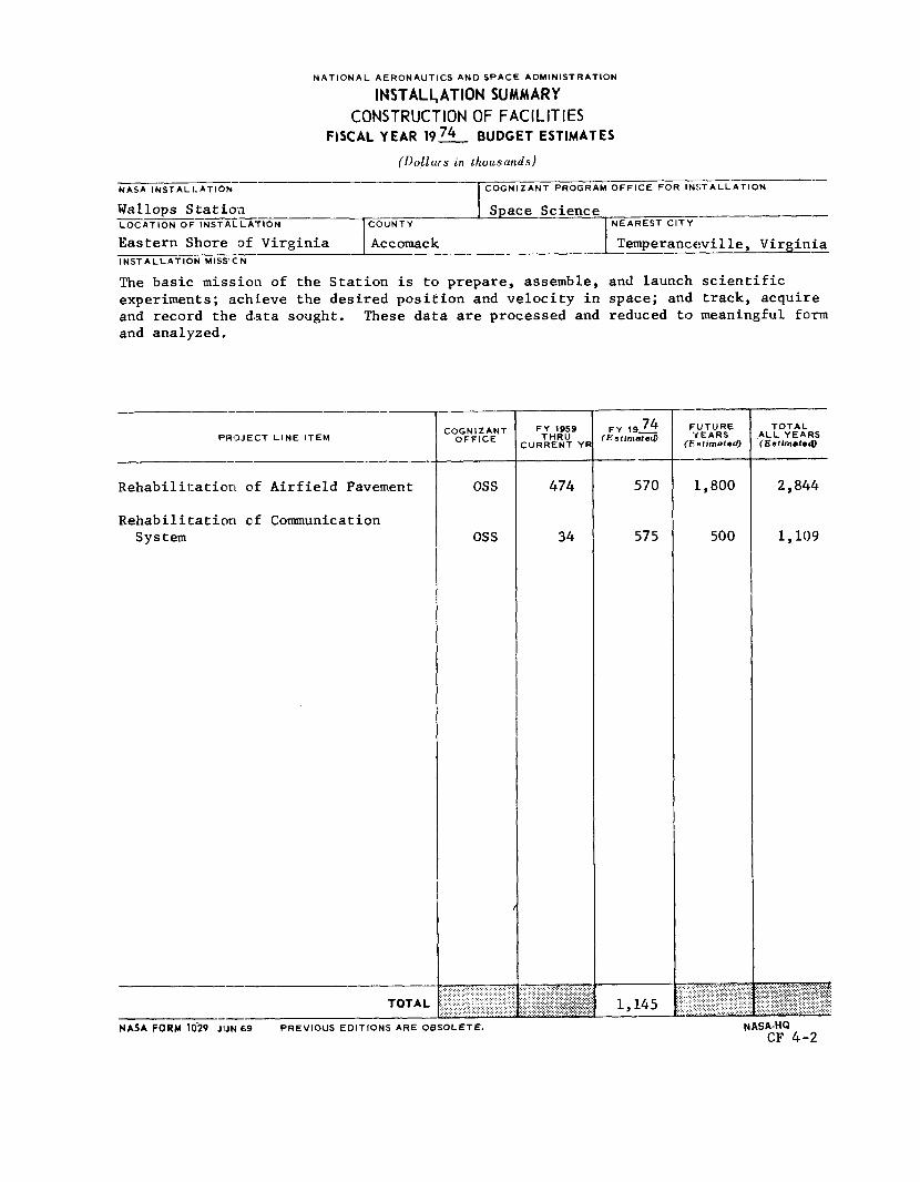
NATIONAL AERONAUTICS AND SPACE ADMINISTRATION
INSTALL, ATION SUMMARY CONSTRUCTION OF FACILITIES
FISCAL YEAR 19% BUDGET ESTIMATES
- NASA I NST A L I. AT I O N
(Dol lars in thousands)
COGNIZANT PROGRAM OFFICE FOR INSTALLATION
--_- Wallops Station I Space Science --- LOCATION OF INSTALLATION 1 COUNTY I NEAREST CITY
PROJECT L I N E ITEM
Rehabilitation of Airfield Pavement
Rehabilitation of Communication System
TOTAL ---
COGNIZANT OFFICE
os s
os s
FY 1959 THRU
:URRENT YF
474
34
. . . , . . . . . .
F Y 19- 74 ( E s t i m a t e d
570
575
1,145
F;UTURE f EARS
(Es t imated )
1,800
500
TOTAL ALL YEARS (Eot i rnate9
2 ,844
I, 109
NASA FORM 1029 JlJN ti9 PREVIOUS EDITIONS ARE OBSOLETE. NASA-HQ CF 4.-2

CONSTRUCTION OF FACILITIES
FISCAL YEAR 1974 ESTIMATES
I----- 1 i PROJECT TITLE Rehab i l i t a t ion of A i r f i e l d Pavement
I L°CArloN t Wallops S t a t i o n
FY 1974 CoF ESTIMATE $570,000 -
COGNIZANT - INSTALLATION: Wallops S t a t i o n
LOCATION O_I:FROJECT: Wallops S t a t i o n , Accomack County, V i rg in i a
COGNIZANT EDGRAM OFFICE: Off ice of Space Science
FY 1973 A N D P R I O R YEARS CoF FUNDING:
Planning and Design Construct ion
$34,000 440,000*
Tota l FY 1973 and P r i o r Years $474.000
*CoF investment subsequent t o t h e t r a n s f e r of t h e f a c i l i t y t o NASA.
SUMMARY PURPOSE AND SCOPE:
The purpose of t h i s p r o j e c t i s t o r e h a b i l i t a t e and improve t h e e x i s t i n g a i r f i e l d pavement a t Wallops S t a t i o n t o make i t more s u i t a b l e f o r unloading a i rc raf t , and t o provide b e t t e r u t i l i z a t i o n of t he e x i s t i n g runways, taxiways, and ramps used i n support of p re sen t and f u t u r e R&D a i r c r a f t p r o j e c t s .
PROJECT JiEII'IF ICATION :
The s t rengthening of t he taxiway f o r Runway 10/28 i s requi red t o m e e t t h e requirements of a i r c r a f t p re sen t ly u t i l i z i n g the a i r f i e l d . t o t h e runway a t p re sen t are over s ec t ions of taxiway paving which are approx- imately 25 percent of t h e runway's design s t rength . t ax ied on the primary runways; t h i s increases the p o t e n t i a l of c o l l i s i o n . This opera t ion i s hazardous during n igh t hours, per iods of r e s t r i c t e d v i s i - b i l i t y , and during per iods of ope ra t ion without p o s i t i v e con t ro l . t he re fo re e s s e n t i a l t h a t t h e taxiways be made f u l l y operable t o e l imina te these undes i rab le opera t ing condi t ions.
A8ccess and egress
A t p re sen t , a i r c r a f t are
It i s
CF 4-3

The cons t ruc t ion of t h e a i r c r a f t parking ramp and t h e s t rengthening of t h e nor th s e c t i o n of Runway 17/35 t o permit i ng res s and egress t o the parking area are required t o comply wi th e x i s t i n g s a f e t y s tandards applying t o t h e loading/unloading of explosives , rocke t motors, etc. The ramp wi.11 provide an area of s u f f i c i e n t load bear ing capac i ty t o support m i l i t a r y and commercial cargo a i rc raf t . The parking area w i l l be equipped wi th a grounding system as required t o minimize e lec t r ica l s t a t i c discharges, i n order t o permit compli- ance w i t h s a f e t y r egu la t ions concerning loading and unloading of hazardous explosive cargo and fue l ing of t h e a i r c r a f t . The p resen t s i t e being u t i l i z e d r equ i r e s t h e c los ing of t he Research Radar F a c i l i t y during explosive handling operat ions. Although a l l nonessent ia l personnel are c l ea red from t h i s area during these operat ions, t he Radar F a c i l i t y valued a t $1.5 m i l l i o n i s s t i l l exposed t o a p o t e n t i a l hazard.
PROJECT DESCRIPTION:
This p r o j e c t . w i l l provide f o r patching as requi red , and a s ix- inch th i ck overlay of approximately 25,000 square yards of t h e taxiway and ramps serv ing Runway 10/28. The overlay w i l l be of bituminous concre te pavement. overlay w i l l be appl ied t o 27,000 square yards of Runway 17/35, and a 3,400 square yard 15-inch t h i c k re inforced concre te parking ramp w i l l be provided. The parking ramp w i l l be designed t o c a r r y s i n g l e wheel loadings of 57,000 pounds . PROJECT COST ESTIMATE :
A similar
---
Unit of Unit Tota l c o s t --- c o s t Measure Quant i ty --
Land Acquis i t ion
Cons t 1: uc t i c g
Rehab i l i t a t e and over lay about 25,000 square yards of taxi.way serv ing runway 10/28
Rehabi l i t .a te about 27,000 square yards of t h e nor th end of ru.nway 17/35 t o include provis ion of 3,400 square ya.rd ramp
Equipment
----- Fa l lou t S h e l t e r (Not Feas ib le )
$570,000
SY 25,000 $9.20 230,000
SY 30,400 11.18 340,000
TOTAL $570,000 -
CF 4-4

FUTURE CCLESTIMATED FUNDING REQUIRED TO COMPLETE THIS PROJECT:
For present ly planned usage t h e r e are no c u r r e n t l y foreseen f u t u r e funding requiremeit:; t o complete t h i s s p e c i f i c p r o j e c t ; however, i t i s estimated t h a t an a d d i t i o n a l $1,200,000 t o $1,800,000 w i l l be required i n f u t u r e years t o complete t h i s general r e h a b i l i t a t i o n of t h e a i r f i e l d pavements a t t h i s s t a t ion.
CF 4-5
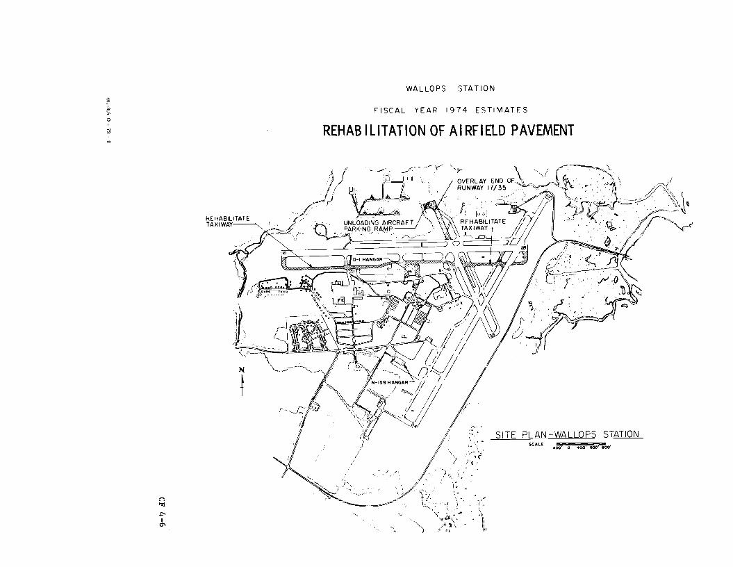
W A L L O P S S T A T I O N
F I S C A L Y E A R 1974 E S T I M A T F S
REHABILITATION OF AIRFIELD PAVEMENT
I QI

CONSTRUCTION OF FACILITIES
FISCAY YEAR 1974 ESTIMATES
'L'I'CAL Rehabilitation of Communication System
Wallops Station
FY 1974 CoF ESTIMATE g 7 5 , O O O
COGNIZANT - INSTALLATION: Wallops Station
LOCATION PROJECT: Wallops Island, Accomack County, Virginia
COGNIZANT - PROGRAM OFFICE: Office of Space Science
FY 1973 A N D - PRIOR YEARS CoF FUNDING:
Planning and Design Cons tru.c t ion
Tota.1 FY 1973 and Prior Years
$34,000 * $34,000
*The existing cormrmnication system was included in major construction activities and is not separately identifiable.
SUMMARY I'URPOSE - AND SCOPE:
The purpc~se of this project is to rehabilitate and upgrade approximately 10,000 1.Fnaar feet of the sounding rocket firing operations communication and insti:unientation cabling system on Wallops Island. replacement: of approximately 6,000 linear feet of deteriorated buried cable with new cabling in an above the ground cable tray on the south end. of the island between Buildings X-65 and 2-35, be made 130 approximately 4,000 linear feet of the underground system between eha Island Terminal (Building X-75) and Blockhouse No. 3 (Building W-20) and an additional 200-pair communication cable will be installed to meet current capacity requirements.
This includes the
In addition, repair will
PROJECT JUSTIFICATION : - The present underground duct system south of the causeway is deteriorating
and overloinded. In several locations the ducts have settled away from the manholes, causing the existing cables to be pinched and cut. In addition, the underground system is under water most of the time due to the very low
CF 4-7

lying terrain on the south end of the Island. The proposed new cable tray system wil.1 provide means of replacing and adding communication, control and :instrumentation cables for all launch areas and facilities south of the causeway on Wallops Island, which includes launch pads 0, 1, 2 and :3 .
The existing underground cabling between the Island Terminal Building and Blockhouse N o . 3 is now loaded to capacity and in need of repairs requiring additional ~iab1.e pins.
It is necessary to install the new and additional cabling as well as repair existing cabling, as appropriate, to provide reliable timing, countdown, instrumentation, and communication between the various launch pads, blockhouses and instrumentation sites.
PROJECT DESCItII?TION:
This project will provide approximately 6,000 linear feet of above ground cable tray system, consisting of six 24-inch wide cable trays along the oceanfront 011 Wallops Island between Buildings X-65 and 2-35, The cable system will include the necessary connections and terminals to serve all launch areas and facilities south of the causeway on Wallops Island. Cable "huts" wF11 be provided for transition of cables from the trays to the exist::ing; underground duct system and to the launch areas. The cable trays wil.1 be supported by aluminum stanchions on concrete foundations.
In addition, repairs will be made to approximately 4,000 linear feet of line as necessary and upgraded by installing 4,000 feet of 200-pair communication cable between Island Terminal Building X-75 and Blockhouse No. 3 Building W-20. The cable will be installed in the existing underground duct syctem, direct-buried, as well as in the existing cable tray system. require a new above ground system. equipment will be provided at both ends of the cable.
This system is on higher ground and therefore does not Necessary terminals and associated
. PROJECT COST ESTIMATE: -
Land Acqui :; i i: ion
Construct ion
Unit of Measure Quantity
Unit Total. cost cost -. -
$575 , OO?
Communi c ia t F on cab 1 e between Buildings X-75 and 67-20 23,000
CF 4-8

Unit of Unit Total Measure Quant i t y c o s t cost --
Commuiication cables LF 4,000 $4.25 (17,000)
Repiair, sp l i c ing , and terminating cable LS --- --- (6,000)
Cable t r a y system 552,000
Foundii t ion and support f o r cab le trays Each 400 350.00 (140,000)
Cable t r ays LF 6 000 30.00 (180 000)
Cable hu t s , t akeoffs , dropouts, etc. LS
Ins tnlmentation and communication cables , sp l iced and terminated LS (212,000)
Equipment --- -e- --- -I- - --- --- e- - --- -- Fal lout She l te r (Not Feasible)
TOTAL $575,000
FUTURE Cop ESTIMATED FUNDING REQUIRED TO COMPLETE THIS PROJFE:
There is a continuing need t o rep lace o the r por t ions of t he i s l and communication and instrumentat ion system estimated a t approximately $500,000. This w i l l probably be accomplished over t h e next f i v e years,.
CF 4-9
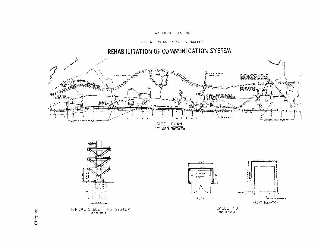
WALLOPS STATION
F I S C A L YEAR 1974 E S T I M A T E S
REHABILITATION OF COMMUNICATION SYSTW
LAUNCH AREAS 3A.38.84 NCH AREAS 0.1.82
S I T E PLAN 2 m z 7 F % R z & SCALE
TYPICAL CABLE TRAY N O T TO S C A L E
t ll'-O. 1
P L A N
SYSTEM
VARIES -
TOP OF YANI(0LE
FRONT ELEVATION
CABLE HUT NOT TO S C A L E
c I

NATIONAL AERONAUTICS AND SPACE ADMINISTRATION
CONSTRUCTION OF FACILITIES
FISCAL YEAR 1974 ESTIMATES
VARIOUS LOCATIONS
Page No.
SuITrma.ry ........................................................... CF 5-1
Of f i ce of Manned Space F l i g h t P ro jec t :
Modificati.on of Power System. .................................. CF 5- 3
Off ice of Space Science P ro jec t :
Modificiitiion of Space Launch Complex 2 West (SLC-2W). .......... CF 5-11
Off i c e of Tracking and Data Acquisition P r o j e c t :
Modification f o r F i r e P ro tec t ion Improvements.. ................. CF 5-16
CF 5
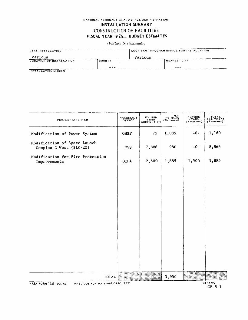
N A T I O N A L AERONAUTICS A N 0 SPACE ADMINISTRATION
IN ST ALh AT ION SUMMARY CONSTRUCTION OF FACILITIES
FISCAL YEAR 1 9 x BUDGET ESTIMATES
(Dollars in thousands) .-__-
NASA I N S T A L I- AT1 ON COGNIZANT PROGRAM O F F I C E FOR I N S T A L L A T I O N
I Various _--_---- NEAREST C I T b
Various -~ COUNTY L O C A T I O N O F I N S T A L L A T I O N
I --- I_ --- -____- --__- --- I N S T A L L A T I O N MISSICIN
P R O J E Z T L I N E I T E M
Modification of Power System
Modification of Space Launch Complex 2 West (SLC-2W)
Modification for Fire Protection Improvements
TOTAL ---
30GN I Z ANT O F F I C E
OMS F
oss
OTDA
NASA FORM 1029 JlJlJ 69 PREVIOUS EDITIONS ARE OBSOLETE.
F Y 1959 THRU
URRENT YF
75
7,886
2,500
F Y 1 9 7 4 IE s I imated
1,085
980
1,885
3,950
F U T U R E YEARS
(Estimated)
-0-
-0-
1,500
"
T O T A L A L L YEARS ( E s t i m e r e a
1,160
8,866
5,885
NASA-HQ CF 5-1

MARSHALL SPACE FLIGHT CENTER FISCAL YEAR 1974 ESTIMATES
MODIF ICATION OF POWER SYSTEM SLI DELL COMPUTER COMPLEX
CONSTRUCTION OF FACILITIES
FISCAL YEAR 1974 ESTIMATES
I--- ------I --+ PROJECT TITLE Modification o f Power System
I + S l i d e l l Computer Complex
M 1974 CoF ESTIMATE $1,085,000 -4 COGNIZANT INSTALLATION: Marshall Space F l i g h t Center
LOCATION OF PROJECT: S l i d e l l , Tammany Par i sh , Louisiana
COGNIZANT PRERAM OFFICE: Off ice of Manned Space F l i g h t
FY 1973 AND S I O R YEARS CoF FUNDING:
Planning and Design Construct i on
$74,500 * Total Fl' 1973 and P r i o r Years $74.500
*This s i t e . w a s t r ans fe r r ed to NASA i n 1963 from the Federal Aviation Agency. About $2.9 mi l l i on of f a c i l i t i e s w a s so t r ans fe r r ed and about $2.4 mil.lion of f a c i l i t i e s work has been accomplished by NASA s i n c e t h a t t i m e .
SUMMARY PURICSE AND SCOPE:
This project. provides f o r t h e i n s t a l l a t i o n of a nominal 750 KVA redundant s t a t i c u n i n t e r r u p t i b l e power system (UPS) as a modif icat ion t o the e x i s t i n g power system a . t t he S l i d e l l Computer Complex (SCC). This modif icat ion i s necessary t o minimize e l e c t r i c a l power i r r e g u l a r i t i e s and lo s ses impacting c r i t i c a l computer equipment and thus t o provide the necessary e f f ec t iveness and rel.iabi.l.it:y required f o r t hese computer and computer-related opera t ions .
PROJECT JUSTIJICATION :
The Sli-dell. Computer Complex (SCC) i s located on a 14-acre government- owned s i t e a t S l i d e l l , Louisiana, about t h i r t y - f i v e m i l e s no r theas t of
CF 5-3 491-315 0 - '73 - 9

New O r l e a n s . and severs1 smaller support bui ldings. A l l of t h e computer equipment i s loca ted i n the l a r g e r main bui ld ing , Computer Operations Off ice Building (COOB). computer support t o test opera t ions a t t h e Miss i s s ipp i Test: F a c i l i t y (MTF), some 1 7 m i l e s t o t h e east , and t o Saturn V s t a g e manufacturing a t t h e Michoud Assembly F a c i l i t y (MAF) about 22 m i l e s t o t he southwest.
It c o n s i s t s of a main three-s tory ” o f f i c e type” bu i ld ing
The SCC w a s e s t ab l i shed by NASA i n 1962 and mainly provided
A t t he present t i m e , t h e SCC houses over $20 mi l l i on of computer, da t a reduct ion and r e l a t e d support equipment. This i s t h e ”book value” o r i n i t i a l a c q u i s i t i o n c o s t of t h i s equipment and i t s replacement c o s t would b e considerably h igher . The mission of t he SCC i s t o provide pre- computer processing, computer processing, s to rage and d i s t r i b u t i o n of da t a , a s w e l l as t o provide computer support . The complex provides s c i e n t i f i c , management, admin i s t r a t ive and engineer ing d i g i t a l computer work and da ta reduct ion , as w e l l as some analog computer service. It a l s o accomplishes key punching, card processing and da ta t ransmission serv ices . mese services a re a v a i l a b l e t o NASA ac t iv i t i e s mainly a t Marshall Space F l i g h t Center (MSFC) , Miss i s s ipp i T e s t Faci:Lity (MTF) , and Michoud Assembly F a c i l i t y (MAF) , including NASA con t rac to r s . These services a re also provided t o o t h e r au thor ized use r s . A t the p re sen t t i m e , t 5 - 9 0 % of the SCC computer workload i s f o r NASA support of space f l i g h t programs.
The SCC:, t he re fo re , provides computational support f o r ass igned NASA programs as w e l l as o t h e r approved programs. inc lude such ones as the Skylab missions f o r which t h e e x i s t i n g l a r g e u n i t processor (U-1108-14) system has been e n t i r e l y dedicated. This da t a , f o r example, w i l l be used as a b a s i s f o r dec i s ions during these f l i g h t s . Addi t iona l ly , t h e u s e o f t h e en t i r e U-1108-14 system by Skylab w i l l then r equ i r e ass igning i t s normal workload t o t h e a l r eady heav i ly loaded mul t i - processor/multiprogramming (U-1108-01) system, making t h e r e l i a b i l i t y of t h i s system doubly important. Other SCC computer support include programs such a E; t.he following :
These p resen t NASA programs
a. Lower Miss i s s ipp i River Forecast ing Center
This element of t he Nat ional Weather Service w a s e s t ab l i shed i n 1971. i n t he SCC and i.s requi red t o f o r e c a s t d a i l y r iver s t ages as w e l l a s t o provide f lood warnings t o an e i g h t s ta te area. Rel iab le computer service i.s mandatory f o r t h i s u se r , e s p e c i a l l y a t t i m e s when commercial power ::s most u n r e l i a b l e , i .e. , during hur r icanes , tornadoes, f loods , e t c . Sc?riou:; c:onsequences, involving l o s s of property o r l ives , could poss ib ly result : from a f a i l u r e of t h i s warning system.
CF 5-4
b. Government Contractor Uses
By f a r t h e l a r g e s t U-1108-01 system use r a t SCC i s a NASA cont rac tor heavi ly involved i n the prepara t ion of f l i g h t t r a j e c t o r i e s and thermal hea t ing analyses of t he Skylab missions. Rapid turnaround of t h i s da t a i s extremely important on many of t hese items, incl.uding a t r a j e c t o r y computation 15 minutes be fo re each launch. This cont rac tor i s a l s o involved i n processing wind tunnel test da t a f o r NASA, t h e Army and the A i r Force. This l a rge - sca l e wind tunnel da t a program i s a l s o com- mi t ted t o a s h o r t turnaround t i m e , as t h e scheduling and use of the var ious wind tunnels i s based on the output from these computer runs.
The SCC i s p re sen t ly opera t ing a t very near i t s maximum capaci ty , with minor except ions, i n support of t h e following:
1. NASA d i r e c t and con t r ac to r act ivi t ies a t MSFC, MAF, MlcF, etc.
2. Other government agencies such as Naval Aeromedical Research a t MAF, the National Data Buoy Pro jec t (Dept. of Commerce), U. S. Geodetic Survey, t he Gulf Ehvironmental P ro jec t a t MTF, and t h e U. S. Fores t ry Service, Federal Communications Commission, and U. S. Maritime Adminis- tra t ion.
Pro jec t ions D f workload from these use r s i n d i c a t e t h a t i n the near fu tu re , a maximum of a v a i l a b l e computer. t i m e w i l l be required.
Although these p r o j e c t s do n o t c u r r e n t l y r equ i r e "real t i m e " computation i n t h e sense of d i r e c t computer a c q u i s i t i o n of da t a from a s a t e l l i t e o r o the r sensor , t he computer does opera te i n a real t i m e mode f o r input and con t ro l of c e r t a i n app l i ca t ions . Also, real time funct ions are performed by the computer f o r a l a r g e number of terminals wherein the computer i s i n t e r a c t i v e with s c i e n t i s t s , engineers and adminis t ra tors . In t h i s regard, these personnel are composing computer programs, updating f i l e s , applying modeling techniques, and solving mathematical processes on l i n e t o t h e computer. When t h e computer f a i l s , i t i s necessary f o r t h e s c i e n t i s t o r o the r person t o r econs t ruc t h i s e n t i r e thought processes , repea t a l l computer i n t e r a c t i o n , o r determine what f i l e s i n computer s to rage have been l o s t , w h a t v a l i d f i l e s can be r e t r i eved from magnetic tape, and then re- cons t ruc t a l l updating t r ansac t ions from t h a t po in t , Use of computer mass s to rage f i l e s f o r da t a banks f o r on- l ine , real t i m e , inqui ry o r up- da t ing purposes i s severe ly l imi ted and expensive unless s t a b i l i t y of computer opera t ion i s m i n t a i n e d .
The SCC i s provided e l e c t r i c a l power by the l o c a l u t i l i t y company by two 34.5 KV feeders t o a subs t a t ion a t the SCC. The dual feeders provide redundancy and s e r v i c e i s switched from one t o the o the r i n event of a
CF 5-5

f a i l u r e . The subs t a t ion , loca ted ad jacent t o t h e SCC maintenance bui ld ing , has a separa te transformer f o r "building loads" and one f o r "e lec t ronics loads," each a t 480/277 v o l t s . This se rv ice i s considered vary good f o r normal usage but no t now adequate f o r SCC computer operat ions.
The SCC has experienced a cons iderable number of computer equipment outages , however , due t o i n s t a b i l i t y and d i scon t inu i ty of t h e commercial power suppl ied by the l o c a l u t i l i t y company. The computer systems must f requent ly b e shut down due t o such v a r i a t i o n s i n and lo s ses of power ranging i n dura t ion from mil l iseconds t o several minutes. These, i n tu rn , may be caused by load switching opera t ions , l i gh tn ing , transmission l i n e f a u l t s , t r a n s i e n t s , e t c . From February 1, 1971, through 1972 the re were recorded a t o t a l of about 65 such outages. Many may be designated a s "bl ink," a term used t o i n d i c a t e a d i s c e r n i b l e drop i n vo l t age of a very s h o r t period (about 1-2 seconds).
A s a general matter, t h i s p r o j e c t does no t dea l wi th a pro:tonged complete d e t e r i o r a t i o n of commercial e l e c t r i c a l power. In the S l i d e l l a r e a , an average of over f i f t e e n high v e l o c i t y windstorms , some approaching hur r icane force , can be expected during a year . For example, t he August 1969 Hurricane Camille deenergized e l e c t r i c a l s e r v i c e t o the complex f o r more than twenty hours and the whole complex w a s n o t r e s to red t o normal opera t ion f o r about two weeks. Remedial a c t i o n dea l ing with cases of prolonged outages w i l l be d e a l t with by a f u t u r e f a c i l i t y p r o j e c t provided f u r t h e r study and the a v a i l a b i l i t y of e x i s t i n g government genera tors j u s t i f i e s t h i s ac t ion . This a r e a i s a l s o sub jec t t o an average of about seventy moderate t o severe e l e c t r i c a l storms p e r year , giving r i s e to vol tage surges and serv ice d i s rup t ion . A s now es t ab l i shed , a computer can expect, on the average, t o become inopera t ive due t o e l e c t r i c a l power se rv ice d i f f i c u l t i e s once every ten calendar days wi th a l o s s of over two hours of production. The impac:t of t h i s s i t u a t i o n i s a s follows:
1. Loss of da t a processing during:
(:a> the t i m e t he power i s o f f , p lus
c:b) the t i m e i t takes t o br ing the system back up, p l u s
(c ) t he t i m e required t o "debug" and repair any hardware f a i l u r e s caused by the outages, p lus
(d) t he t i m e l o s t i n t he reruns made necessary by runs which a r e no t f i n i shed a t t h e t i m e of t h e outage.
2. The c o s t of r epa i r ing o r rep lac ing damaged hardware caused by t h e outage.
CF 5-6

3 . Increased maintenance c o s t s t o t h e equipment.
4 . Redul=.ed l i f e of t he equipment a s a r e s u l t of component damage throiigli thermal shock and electrical ove r s t r e s ses t h a t t ake plac'e during an abnormal "cycle down" and outage per iod.
5 . Incr'sased sof tware development c o s t s i n c e r t a i n ins tances .
To evolve an es t imate of the probable c o s t of electrical outages, c e r t a i n general assumptions must be made. Using such conserva t ive as- sumptions, a r a t iona l i zed c o s t of outages on an annual b a s i s i s between $140,000 and $315,000 based on equipment c o s t only. a t i n g personiie:l and o the r c o s t s a r e added, these annual amounts would be increased si:gn:ificantly. program slip:?ages and l i k e impacts. Recognizing the d i f f i c u l t i e s of quant i fying every a spec t of t hese c o s t s , i t is , however, r e a l i s t i c a l l y estimated t h a t the t o t a l could w e l l be on the order of $500,000 p e r year. It i s then r e a d i l y seen, t h a t t h e provis ion of more r e l i a b l e e l e c t r i c power, i3s proposed by t h i s p r o j e c t , i s very c o s t e f f e c t i v e i n add i t ion t o being a l>as:ic and urgent SCC opera t iona l requirement.
I f the c o s t s of oper-
To t h i s t o t a l could be added the c o s t of
In a sumnary manner, the requirement f o r t h i s p r o j e c t a t t h i s t i m e has been brought about by the i n s t a l l a t i o n of l a r g e r capac i ty , more complex and more s e n s i t i v e equipment, t h e much more d i f f i c u l t t a s k of analyzing the impact o f equipment f a i l u r e s with t h e newer equipment, the l a r g e r volume output now required r e s u l t i n g i n less redundant/standby equipment and the recertt changes i n the s t a t e -o f - the -a r t i n computer s e rv i ces i n - volving more terminals , g r e a t e r on - l ine use and less manual con t ro l and d i r ec t ion .
PROJECT DESCRIPTION:
It i s intended, under t h i s f a c i l i t y p r o j e c t , t o modify the e x i s t i n g e l e c t r i c power system t o provide a s ta t ic r e c t i f i e r l i n v e r t e r type, b a t t e r y supported, u n i n t e r r u p t i b l e power (UPS) augmentation. This w i l l be of a nominal 750 KVA redundant capac i ty and i n s t a l l e d a s a modif icat ion of t h e e x i s t i n g system i n such a manner a s t o in su re the supply of r e l i a b l e e l e c t r i c power t o t h e computer system. This modif icat ion has been s ized t o provide such power t o the estimated 640 KVA e l e c t r o n i c (computer) loads only. involved i s the provis ion of a 2,000 square f o o t f a c i l i t y , now planned a s an add i t ion t o the e l e c t r i c equipment room of the COOB, t o house t h e add i t iona l equipment. Addit ional c i r c u i t breakers , cab l ing and conduit work w i l l a l s o be required.
'I'he IJPS envisioned i s of a s tandard commercial type and s i z e . Also
CF 5-7

PROJECT COST ESTIMATE : ---
-- Land Ac:quisi t i o n
Unit of Unit To ta 1 c o s t Measure Quantity Cost -- --- - -. - e - -
Construction $125,000 --- --- --- l o , 000 S i t e work LS
SF 2,000 $30.00 60,000 Bu:&ling add i t ion El.c?cl:rical modif icat ions LS --- --- 55,000
Equipment
S t a t i c UPS Bat tery support
960,000
--- --- 715,000 245,000
LS LS - -e ---
--- --- - -- -I- - Fa l lou t She l te r (Not Feas ib le ) -- TOTAL $1.085.000
--- FUTURE CoF ESTIMATED FLJNDING TO COMPLETE THIS PROJECT:
N o a d d i t i o n a l funding w i l l be required t o complete t h i s p r o j e c t ; how- ever , i f j u s t i f i e d by l a t e r study it may be necessary t o provide coverage f o r pmlonged e l e c t r i c power outages. This reques t i s not. now considered j i i s t i f ied but changed condi t ions l a t e r could poss ib ly ju s t . i fy the add i t ion 0 . E an ,auxi l ia ry generat ing p l a n t a t least t o provide f o r "'building loads ."
CF 5-8

r--- I
MARSHALL SPACE FLIGHT CENTER
MODIF ICATION OF POWER SYSTEM
FISCAL YEAR 1974 ESTIMATES
SLIDELL COMPUTER COMPLEX
?--? ?i
li UTI L ITY COMPANY ' :S SUBSTAT ION
Ul ILITY COMPANY'S 34. KV SWITCH STATION
PARTIAL SITE PLAN -- F\J
(NOT TO SCALE ) CF 5-9

MARSHALL SPACE FLIGHT CENTER FISCAL YEAR 1974 ESTIMATES
MODiFiCATiON OF PUiiER SYSTEM SLIDELL COMPUTER C O M P L E X
I
& 1-2500 UVA I U T I L I T Y CO. y1, SUBSTATIOR
i 2-1000 KVA + I
I I MhIf iTMANCE
I
BUILDING,, e - - - f --A ADDITION
SEPARATE CIRCUITS SO THAT EACH COMPUTER SYSTEM I S SUPPLIED FROM SEPARATE MAIN DISTRIBUTION PANELS
\ L
WIRE CLOSET 106
ClAT3
ClATZ w C l A T l
L WIRE CLOSET 102
PANEL a C1 C T l
C1 CT2
ClCT3
- EXISTING - PROPOSED - \-EX:STING FEEDERS 1
i TO WIRE CLOSETS

CONSTRUCTION OF FACILITIES
FISCAL YEAR 1974 ESTIMATES
/PROJECT TITLE Modification of Space Launch Complex 2 West (SLC-2W) ILOCATION John F. Kennedy Space Center - Western Test Range FY 1974 CoF ESTIMATE $980,000 I--__
COGNIZANT -- IN!;TALLATION: John F. Kennedy Space Center
LOCATION ---- OF I?ROJECT: Vandenberg Air Force Base - Western Test Range (WTR), California
COGNIZANT PROGRAM OFFICE: Office of Space Science
FY 1973 AND :gCOR YEARS CoF FUNDING:
Planning and Design Construct ion
$453 , 375 7,432,178
Total FY 1973 and Prior Years $7,885,553
SLJMMARY PURPOSJ3 AND SCOPE:
The purpose of this project is to modify and improve the safety of launch complex SLC-2W, WTR, to make the complex compatible with the planned new Delta vehicle configuration involving the extended Thor Booster with the RS-27 (H-1) engine and 3, 6, or 9 Castor I1 thrust augmentation motors. In addition, the capability must be maintained to support the present Delta second stage and 65-inch diameter fairing which will be used on some mission:;: with this extended booster, and the modified Delta second stage and 8-foot diameter aerodynamic fairing which will be used on subsequent missions with this booster.
This project includes the replacement of the SLC-2W complex vehicle air conditioning system and the installation of improved high intensity perimeter lighting to improve the efficiency and minimize the hazards associated with night operations.
CF 5-11 491-315 0 - 73 - 10

PROJECT JUSTWJCATION:
The SLC-2W is the only active complex at the Western Test Range capable of accommodating the assembly, prelaunch checkout and launch of the Delta vehicle. Spiactzcraft size, weight, and orbital parameters have dictated various changes in the launch vehicle configuration. These changes require in turn, the adaptation of the launch facilities to assemble, fuel and launch the new vehicle configuration. because the inventory of older first stages will be depleted and only the new configurations will be available for launch.
These modifications are necessary in FY 1974
Significant operational problems were experienced in FY 1973 with the comp1.e~ air conditioiiiig units during the ERTS A launch preparations. were obtainel3 i l S surplus from the Atlas Agena program at Eastern Test Range, are approximately 13 years old, and replacement parts are no longer available to maintain reliable operations.
These units
There are no other facilities available to support the launch requirement for Delta polar orbiting missions. Therefore, these changes are mandatory.
PROJECT DESCRIPTION: -- The project will modify the working platforms on the mobile service tower
to match the electrical, mechanical and fueling access panels and doors which will be approximately 10 feet higher on the extended vehicle. New openings will be made in the sliding doors to accommodate the relocated umbilicals. The necessary nechanical and electrical changes to support the c:hanges in the platforms are included in the project. ning arrestor will be modified to provide a 45' cone of protection, and other safety features, such as guardrails, will be provided.
In addition, the existing light-
Pad lighting to be provided includes additional area lighting utilizing 1,000 watt quartz-iodine lighting units installed on poles at the LOX facility, RP-1 fuel facility, pad trailer area, and service structure storage area to provide a minimum of 25 foot candles at working levels. units and light poles will be utilized to the maximum extent.
Existing lighting
CF 5-'12
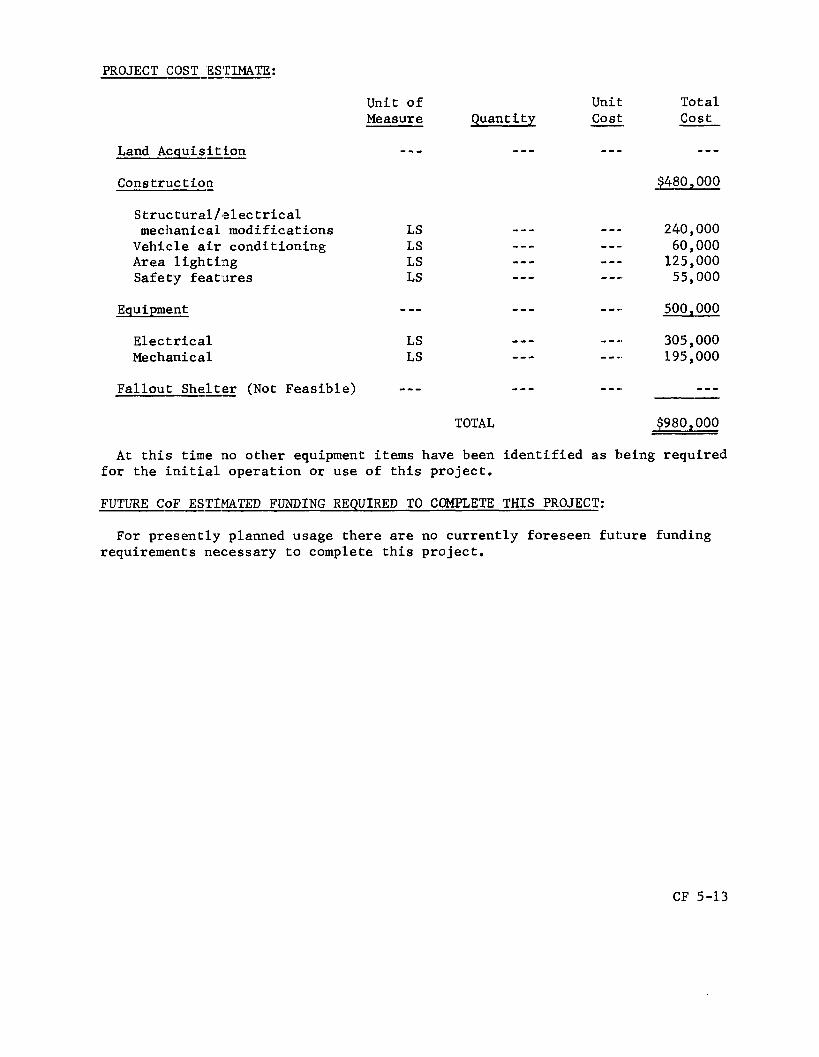
PROJECT COST ESTIMATE:
Land Acquisition
Construction
S tructural/el ec trical
Vehicle air conditioning Area lighting Safety featnes
mechanical modifications
Equipment
Electrical Mechanical
Fallout She&= (Not Feasible)
Unit of Unit cost Measure Quanti t y -.
- - - --- - - -
LS LS LS LS
LS LS
--- TOTAL
Total cost
$480,000
240,000 60 000 125,000 55,000
500,000
305 000 195,000
--- $980,000
At this time no other equipment items have been identified as being required for the initial operation or use of this project.
FUTURE CoF ESTIMATED FUNDING REQUIRED TO COMPLETE THIS PROJECT:
For presently planned usage there are no currently foreseen future funding requirements necessary to complete this project.
CF 5-13

JOHN F. KENNEDY SPACE CENTER, NASA WESTERN TEST RANGE
FISCAL YEAR 1974 ESTIMATES
LOCATION P L A N
0 PROPOSED FISCAL YEAR 1974 PROJECT
1. MODIFICATION OF SPACE LAUNCH COMPLEX 2 WEST (LC-2WI V
V A f B. CALIF.

JOHN F KENNEDY SPACE CENTER NASA FISCAL YEAR 1974 ESTIMATES
MODlFi CATION OF SPACE LAUNCH COMPLEX-2 WEST (SLC-2W)
BLOCKHOUSE
UMBILICAL TOWER
LAUNCH OPERATIONS BUILDING IOBILE SERVICI STRUCTURE
t SPACE LAUNCH
COMPLEX 2
PI
CONSTRUCTION OF FACILITIES
FISCAL YEAR 1974 ESTIMATES
~~ ~
PROJECT TITLE Modif icat ion f o r F i r e P ro tec t ion Lmprovements
LOCATION Various Spacef l igh t Tracking and Data Network S t a t i o n s
FY 1974 CoF ESTIMATE ,$1,885,000 .
COGNIZANT IIJSJALLATION: Goddard Space F l i g h t Center
LOCATION OF PECOJECT: Spacef l igh t Tracking and Data Network S t a t i o n s
COGNIZANT -- PItOGRAM OFFICE: Off ice of Tracking and Data Acquis i t ion
FY 1973 AND - PELIOR YEARS CoF FUNDING:
Planning and Design Cons txuc t::ion
$183,000 2,317,000*
Tota l $7: 1.973 and P r i o r Years $2.500.000
*This cons t ruc t ion c o s t relates only t o the modif icat ions f o r f i r e p ro tec t ion funded i n p r i o r yea r s CoF.
SUMMARY PURPOSE - AND SCOPE :
This i s the fou r th increment of t h e program t o provide f i r e p ro tec t ion f o r This program, which w a s t he t racking and d a t a a c q u i s i t i o n network s t a t i o n s .
i n s t i t u t e d :in 1970, c o r r e c t s t he more se r ious d e f i c i e n c i e s i d e n t i f i e d by a thorough sui:vc?y of each s t a t i o n conducted by f i r e p ro tec t ion engineers and consul tan ts , , realist:ical.:ly requi red by these s t a t i o n s t o reduce the most c r i t i ca l r i s k s .
It provides those measures of f i r e p ro tec t ion prudent ly and
PROJECT J US"IIrICATI0N :
A t these s t a t i o n s , genera l ly f i r e p ro tec t ion f o r f a c i l i t i e s and t echn ica l equipment has lagged t h e in t roduc t ion of newly recognized and more s t r ingent : f i r e p ro tec t ion s tandards e s p e c i a l l y f o r t h e t echn ica l ( e l e c t r o n i c ) equip- ment. For example, r ecen t rev ised f i r e p ro tec t ion s tandards f o r e l e c t r o n i c equipment have introduced the requirement f o r w a t e r s p r i n k l e r sys t ems f o r e l e c t r o n i c equipment ( inc luding computers) opera t ing area.
CF 5-16

Very few d e f i c i e n c i e s were discovered by t h e survey made by f i r e p ro tec t ion engineers and consu l t an t s t h a t would s i g n i f i c a n t l y con t r ibu te t o l o s s of l i f e by f i r e . I n add i t ion , t h e r e were no problems pecu l i a r t o t racking and d a t a a c q u i s i t i o n s t a t i o n s which could no t be cor rec ted by s tandard methods. Consideration, however, had to be given t o the f a c t t h a t due t o the i s o l a t i o n of t racking s t a t i o n s from e s t a b l i s h e d communities, s t a t i o n opera t ions personnel alone must provide an adequate level of f i r e p ro tec t ion . Therefore, t h i s program wits i n s t i t u t e d and designed t o provide the e l e c t r o n i c engineer, the e l e c t r o n i c technic ian , t he power p l an t opera tor , etc., wi th the necessary c a p a b i l i t y t o p r o t e c t t racking s t a t i o n equipment and f a c i l i t i e s .
PROJECT DESCRII?TI:ON : -- Using the f i r e p ro tec t ion survey f o r a b a s i s , t h i s program provides f o r t h e
following: i nc rease i n water supply, s to rage and d i s t r i b u t i o n systems, s p r i n k l e r systems, de t ec t ion systems, r e l o c a t i o n of day tanks e x t e r n a l t o bu i ld ings , i n - s t a l l a t i o n of remote shutdown switches f o r e l e c t r o n i c systems and u t i l i t y systems, pressure pumps, hose houses, etc. This p r o j e c t w i l l complete the s torage, d i s t r i b u t i o n , s p r i n k l e r and de tec t ion systems a t Quito, Ecuador; H a w a i i ; Orrora l , A u s t r a l i a ; Network T e s t and Training F a c i l i t y , Greenbelt , Md.; Ascension I s l and ; Guam; Honeysuckle, Aus t r a l i a ; Goldstone (JPL) , Ca l i fo rn ia ; and the MILA STDN S t a t i o n , F lor ida . Necessary resources w i l l be a l l o c a t e d a s i nd ica t ed i n the following t a b l e :
S t a t i o n -
Qui t o Orrora l NTTF H a w a i i Mila A s cen s ion Honeysuckle Guam Golds tone
TOTAL - - $235 ---
(Dol la rs i D i s t r i b u t i o n
$179 60
238
273 70
--- ---
$820
Thousands) Spr ink le r
$35 40
180 40 25 95 35 60
$5 10
Detect ion
- - - $28
42 25 7 2 35 38
---
---
$240 $80
Tota l -- $214 148 180 37 0
50 5 15 170 158 80
31.885 --
CF 5-17

PROJECT CClS'I - ESTIMATE :
Unit of Mea s u r e
Land Acquis i t ion - - - - Construction
Arch i t e c t u r a1 Mechanical Electrical
LS LS LS
Equipment LS
Fa l lou t She l t e r (Not Feas ib le ) - - - ----
Tota l c o s t --
$1,687,090
449 , 000 970,000 268 , 000
198,000
$1 .8 85.004
A t t h i s time no o the r equipment i t e m s , e i t h e r c o l l a t e r a l o r non-co l l a t e ra l , have been i d e n t i f i e d as being requi red f o r t h e i n i t i a l opera t ion or use of t h i s p ro jec t .
FUTURE CoF - ESTIMATED FUNDING REQUIRED TO COMPLETE THIS PROJEC'll:
Approximately $1,500,000 w i l l probably be requi red t o complete the F i r e P ro tec t ion Modif icat ions t o t h e Spacef l igh t Tracking and Data Network (STDN) and Deep Space Network (DSN). This requirement w i l l be considered i n f u t u r e years.
CF 5-18
NATIONAL AERONAUTICS ANI) SPACE ADMINISTRATION
CONSTRUCTION OF FACILITIES
FISCAL YEAR 1 9 7 4 ESTIMATES
SPACE SHUTTLE FACILITIES
P a g e No. - S u ~ r y . . . ....................................................... CF 6-1
Office of Manned Space F l i g h t P r o j e c t s :
S p a c e S h u t t l e F a c i l i t i e s . . . . . . . . . . . . . . . . . . . . . . . . . . . . . . . . . . . . . . CF 6-2
CF 6
491-315 0 - 7 3 - 11

NATIONAL AERONAUTICS AND SPACE ADMINISTRATION
INSTALhATION SUMMARY CONSTRUCTION OF FACILITIES
FISCAL YEAR 1 9 7 4 BUDGET ESTIMATES
(Dol lurs in thousunds) -_-
NASA INSTALL AT1 O N
--.__--- -.-- ---
1NSTALLATIC)N MISS1 3N
--- -____
PR0JE:CT L I N E ITEM
-_- -___
Space Shut t le F a c i l i t i e s OMSF
-_- -___
NASA FORM 1029 JUN 69 PREVIOUS EDITIONS ARE OBSOLETE.
F Y 1959 THRU
URRENT Y F
i6 925
FY 19- 74 E s t i m a t e d
67,200
67 20C -
FUTURE YEARS
'Estirnafed)
TOTAL 4 L L YEARS (EafimafecQ -----
Not Applicable
NASA-HQ CF 6 - 1

CONSTRUCTION OF FACILITIES
FISCAL YEAR 1974 ESTIMATES
FY 1974 CoF ESTIMATE
PROJECT TITLE Space s h u t t l e F a c i l i t i e s
- COGNIZANT INSICALLATION - : Various Locations
LOCATION OF PIX0.JECT: Locations are as i d e n t i f i e d i n t h e following documentation.
COGNIZANT PRO(ZM OFFICE: Off ice of Manned Space F l i g h t
FY 1973 AND PIZIR YEARS CoF FUNDING:
Planning and Design Cons t ruc t io i i
$9,025,000 47,900,000
Total FY 1973 and P r i o r Years $56.925.o00*
*For Space Shu t t l e f a c i l i t i e s only and exc lus ive of R&D resources ($18.7 mi l l ion) d i r ec t ed t o f a c i l i t y modif icat ions mainly a t Santa Susana, Cal i forn ia , f o r engine component tes t f a c i l i t i e s . The f a c i l i t y planning and design funds assoc ia ted with each sub- p ro jec t a r e a l s o included i n t h e d e t a i l e d following documentation. The p r i o r year cons t ruc t ion c o s t assoc ia ted with each subproject , unless otherwise noted, r e f l e c t s t h e cu r ren t "Book Value" o f - the s p e c i f i c Eac i l i t y being modified, i n so fa r as i t can be reasonably determined.
SUMMARY PURPOSE- AND SCOPE:
The purpose o f t h i s p r o j e c t i s t o r e h a b i l i t a t e , modify and add t o ex i s t ing governrnent-owned f a c i l i t i e s and cons t ruc t new f a c i l i t i e s t o m e e t requirements 3eiierated by and i n support of t h e Space Shu t t l e pragram. FY 1974, these requirements f a l l i n t o th ree main areas:
I n
1. Research and Development F a c i l i t i e s required f o r research, develop- ment, t e s t i n g , evaluat ion and q u a l i f i c a t i o n of each key element clf t h e t o t a l
CF 6-2

system, such a s developmental t e s t i n g of t he a u x i l i a r y propuls ion system and a u x i l i a r y power u n i t f o r the o r b i t e r ; v e r i f i c a t i o n of t he av ionics f l i g h t hardwa.re system and o r b i t e r thermal p ro tec t ion systems; developmental and acceptanc.e t e s t i n g of t he o r b i t e r propuls ion system; and s t r u c t u a l t e s t s of t he ex terna l tank.
2 . Manuf'ac tu r ing and Fina l Assembly F a c i l i t i e s required f o r t he manufact:ure and. assembly of c e r t a i n components of t h e o r b i t e r ; the f i n a l assembly and ch.eckout of t he o r b i t e r veh ic l e ; and the manufacture, f i n a l assembly and checkout of t h e ex terna l tank.
3. Launch and Landing F a c i l i t i e s required f o r landing the o r b i t e r v e h i c l e a f te r - t:he r e t u r n from a space mission and f o r landings inc ident t o orbit :er f e r r y f l i g h t s .
BRIEF PROJECTJUSTIFICATION :
The FII 1973 program provided the funds t o complete t h e f a c i l i t y modifi- ca t ions required f o r the main engine t e s t i n g requirements; modif icat ions and add i t ions t:o t he research and development f a c i l i t i e s a t Marshall Space F l i g h t Center, Huntsv i l le , Alabama, and Manned Spacecraf t Center, Houston, Texas; the e a r l y phase of required modif icat ions t o ex i s t ing government-owned f a c i l i t i e s f o r t he manufacturing and f i n a l subassembly of t he o r b i t e r ' s ex te rna l propel lan t tanks a t Michoud Assembly F a c i l i t y , N e w Orleans, Louisiana; and the i n i t i a l phase of the modif icat ions t o ex i s t ing government-owned f a c i l i t i e s a t NASA I n d u s t r i a l P l an t , Downey, Cal i forn ia , 501: the program management, engineering, manufacturing and subassembly of t he o r b i t e r ' s crew module, forward and a f t fuselage. This proposc:tf FY 1974 program continues and extends these s p e c i f i c i n - crement:; of izhe FY 1973 Space Shu t t l e f a c i l i t i e s program. Included i n t h i s p r o j e c t a r e t h e requirements f o r :
1. Modi:?ications t o the research, development and v e r i f i c a t i o n f a c i l i t i e s a': White Sands T e s t F a c i l i t y , White Sands, New Mexico; Manned Spacecraf t Center, Houston, Texas; Miss i ss ippi T e s t F a c i l i t y , Bay S t . Louis, 14issi:;sfippi; and Marshall Space F l i g h t Center, Huntsv i l le , Alabama.
2. A follow-on phase of the modif icat ions t o e x i s t i n g government- owned f a c i l i titss required f o r manufacturing, f i n a l assembly and checkout opera t ions oE t h e o r b i t e r v e h i c l e and external tank. These include the NASA I n d u s t r i a l P lan t , Downey, Cal i forn ia , f o r f a b r i c a t i o n and subassembly of o r b i t e r components including t h e forward and a f t fuselages and crew module, and the Michoud Assembly F a c i l i t y , N e w Orleans, Louisiana, t o accommodate the manufacturing, assembly and f i n a l checkout of t he ex terna l tank. ' h e A i r Force P lan t $142, Palmdale, Cal i forn ia , i s a l s o to be modified t o accommodate the assembly of major s ec t ions and f i n a l assembly and check- out of the Space S h u t t l e o r b i t e r vehic le . These e f f o r t s w i l l complete t h e
CF 6-:3

c u r r e n t l y foreseen programnatic needs f o r manufacturing f a c i l i t i e s wi th t h e exception of f a c i l i t y requirements a t government p l a n t s t h a t may b e generated by subcont rac tors no t y e t s e l e c t e d and by t h e p o s s i b l e f u t u r e need f o r a d d i t Lorial production capac i ty f o r ex te rna l tanks a t Michoud Assembly F a c i l Lty.
3. The inLt:Lal phase of t h e cons t ruc t ion of t he launch and landing f a c i l i t i e s a t John F. Kennedy Space Center, Merritt Is land, F lo r ida , which inc ludes t h e o r b i t e r landing f a c i l i t i e s .
PROJECT DESCRIPTKON:
This p r o j e c t p,rovides f o r necessary modi f ica t ions and a d d i t i o n s t o e x i s t i n g research and development f a c i l i t i e s , manufacturing and f i n a l assembly f a c i l i t i e s , and t h e i n i t i a l cons t ruc t ion of launch and landing f a c i l i t i e s i n support of t h e Space S h u t t l e program. of n ine subpro jec ts shown under t h e Sumnary P r o j e c t Cost Estimate.
It is comprised
SUMMARY PROJECLCOST ESTIMATE:
Research and Dleveloprnent Fac i l i t i es . . . . . . . . . . . . . . . . . . . . . . . . . . . Manufacturing and F ina l Assembly Faci l i t ies . . . . . . . . . . . . . . . . . . . Launch and Landing Fac i l i t i es .................................
Tota l
PROJECT COST EEIMATES :,
Research and Ige lopmen t F a c i l i t i e s ........................... Modif icat ions f o r Auxi l ia ry Propulsion and Power Systems Test: Facil i t ies, White Sands Test F a c i l i t y , New Mexico .................................................. Modif icat ions fo r S h u t t l e Avionics In t eg ra t ion Laboratory, Manned Spacecraf t Center, Texas.................
Modificatioris f o r Radiant Heating V e r i f i c a t i o n F a c i l i t y , Manned Spacecraft Center, Texas.............................
Modif icat ions f o r t h e Orb i t e r Propulsion System Test F a c i l i t i e s , Mis s i s s ipp i T e s t F a c i l i t y , Mississippi. . . ....... Modif icat ions f o r External Tank S t r u c t u r a l T e s t F a c i l i t i e s , Marshall Space F l i g h t Center, Alaba ma.......................
$19,490 , 000 19,510,000 28,200,000
$67.200.000
$1 9,490,000
1,290,000
1 , 240,000
1 , 260,000
11,300,000
4 , 400,000
CF 6-4

Manufacturia; and F ina l Assembly F a c i l i t i e s ................... Modification of Manufacturing and Subassembly Fac i l i t i es f o r t h e Orb i t e r , NASA I n d u s t r i a l P l a n t , Downey, Ca1iforn:ia ................................................... Mod:ifica.tion of and Addition t o F ina l Assembly and Checkout F a c i l i t i e s f o r t h e Orb i t e r , A i r Force P lan t #42, Palrndale, Ca l i fo rn ia . . . . .................................... Modification of Manufacturing and F ina l Assembly F a c i l i t i e s f o r External Tanks, Michoud Assembly F a c i l i t y , Louisiana ....
Launch and Landing F a c i l i t i e s ................................. --- Construction of Orbi te r Landing F a c i l i t i e s , John F. Kennedy Space Center, F lor ida ...............................
Total
PROJECT DOCWENTATION: -
m e r e follows, i n t h e o rde r of t h e above l i s t i n g , a d e t a i l e d desc r ip t ion (and c o s t estimate f o r each subpro jec t .
$19,510,000
2 , 650,000
7 , 3 50,000
9 , 510 , 000
$28,200,000
28,200,000
3-
j u s t i f i c a t i o n , ,
CF 6-5

CONSTRUCTION OF FACILITIES
FISCAL YEAR 1974 ESTIMATES
PROJECT TITLE !Vlodifications fo r 'Aux i l i a ry Propulsion and Power Systems 'rest F a c i l i t i e s
LOCATION White Sands T e s t F a c i l i t y
FY 1974 CoF ESTIMATE $1,290,000
COGNIZANT INSTALLATION: Manned Spacecraf t Center
LOCATION OF PROJECT: Las Cruces, Dona Ana County, N e w Mexico
COGNIZANT PROGXAJ OFFICE: Off ice of Manned Space F l i g h t
FY 1973 AND PEE2 YEARS CoF FUNDING:
Planning and Design Construction
$99,000 * Total FY 1973 and P r i o r Years $99.000
"This bas i c f a c i l i t y w a s constructed under Section l ( c ) of t he 1963 NASA Authorization A c t . The cu r ren t "Book Value" involved i s about $:L1.,8 mi l l ion .
SUMMARY PURPOSEAND SCOPE :
This p r o j e c t provides f o r t h e modif icat ion of t h ree e x i s t i n g a l t i t u d e These test s tands test s tands a t t he White Sands T e s t F a c i l i t y (WSTF).
w e r e o r i g i n a l l y h i l t t o support t h e development of the lunar module and t h e command se:rvj.ce module f o r t h e Apollo program. The proposed modifi- ca t ions are e s s e n t i a l t o t he development of t he Auxil iary Propulsion System (AX) arid the Auxil iary Power Unit (APU) f o r t h e Space Shut t le .
PROJECT JUST1F:CCATION :
'Ihe Auxiliary Propulsion System f o r t h e Space Shu t t l e o r b i t e r i s t o be made up of two primary systems, each of which w i l l r equ i r e extensive developmental and q u a l i f i c a t i o n t e s t i n g before t h e o r b i t e r can be committed t o space f l i g h t .
CF 6-6
The f i r s t such system is the Reaction Control System (RCS), cons i s t ing of some 30-34 s m a l l engines, each having a t h r u s t range of about 800-1,000 pounds. Thi:; system i s requi red by t h e o r b i t e r i n o rde r t h a t i t may be a b l e t o accorip1.ish a l t i t u d e con t ro l and make small v e l o c i t y changes whi le t h e v e h i c l e ;Is i n o r b i t or during docking and undocking maneuvers, as w e l l as during v e h i c l e descent . The second system i s t h e Orb i t a l Maneuvering System (OMS), which w i l l u se two rocket engines, each having approximately 10,000 pound:; of t h r u s t . This system i s necessary to e f f e c t m a j o r o r b i t adjustments a f t e r t h e o r b i t e r v e h i c l e has a t t a i n e d o r b i t a l v e i o c i t y , as w e l l as t o mikc! o r b i t c i r c u l a r i z a t i o n s and o r b i t t r a n s f e r s . To perform t h e requi red test program under simulated a l t i t u d e condi t ions , modif ica- t i o n s o f exi:;tj.ng Test Stands 401 f o r OMS t e s t i n g , and 403 f o r FLCS t e s t i n g are necessary.
The 0rbi te . r w i l l a l s o conta in an Auxi l ia ry Power Unit (APU) requi red as backup power f o r the v e h i c l e primary power system as w e l l as being a primary power source f o r t h e o r b i t e r hydrau l i c system. The APU must be capable of opera t ing unde:r a wide range of a l t i t u d e s and pressures . To provide f o r t h e requi red developmental t e s t i n g o f t h i s u n i t i nd iv idua l ly , as w e l l as t o provide c a p a b i l i t y f o r an in t eg ra t ed t e s t i n g of t h e primary and a u x i l i a r y power u n i t s.ys t e m s , modif icat ion to e x i s t i n g T e s t Stand 302 w i l l be necessary.
The White Sands Test F a c i l i t y w a s s e l ec t ed as the s i t e f o r t hese develop- mental t es t a c t i v i t i e s because of t h e unique c a p a b i l i t i e s e x i s t i n g a t t h i s l oca t ion . These c a p a b i l i t i e s inc lude t h e a v a i l a b i l i t y of a l t i tu .de test s tands supported by t h e hypergol ic f u e l s to rage and t r a n s f e r syz t e m s t h a t w e r e used f o r Apollo and are now requi red f o r t h e Space Shu t t l e . The se l ec t ed o r b i t e r con t r ac to r , as w e l l as s t u d i e s , has ind ica ted t h a t t h i s f a c i l i t y provides t h e optimum s i t e s f o r t h e above ou t l ined t e s t programs.
To meet Space S h u t t l e program requirements, system level "hot f i r i n g " of t h e RCS/OMS must be i n i t i a t e d by t h e end of calendar year 1975. t h i s goal , f i s c a l year 1974 resources w i l l b e necessary f o r t h i s work.
To achieve
PROJECT DESCRIPTION:
This p r o j e c t provides f o r modif icat ions t o T e s t Stands 401 and 403 for simulated a l t i t u d e t e s t i n g of the S h u t t l e ' s o r b i t e r maneuvering system and r eac t ion con t ro l system, respec t ive ly . T e s t Stand 302 w i l l a l s o b e modified f o r the a u x i l i a r y power u n i t developmental t e s t i n g .
The modif icat ion t o T e s t Stand 401 inc ludes provis ion f o r a t h r u s t mount i n s i d e t h e a l t i t u d e chamber s p e c i f i c a l l y configured f o r t h e OMS engine. Chamber plat.forms w i l l a l s o b e modified t o provide appropr i a t e access t o t h e tes t hardware.
CF 6-7

The work a t Test Stand 403, requi red f o r RCS t e s t i n g , w i l l i nc lude t h e r e l o c a t i o n and i n s t a l l a t i o n nea r t h e s t r u c t u r e of a 13,500 ga l lon e x i s t i n g s to rage tank f o r l i q u i d n i t rogen s torage , p rovis ion f o r a l i q u i d n i t rogen t r a n s f e r system t o t h e stand chamber and t h e i n s t a l l a t i o n of e x i s t i n g panels i n s i d e the chiamber. The n i t rogen cooled panels are necessary to absorb t h e h e a t energy from t h e h o t f i r i n g s . The e x i s t i n g gaseous n i t rogen system w i l l be modified and adapted f o r t h e test opera t ion . Changes t o t h e d i f f u s e r e j e c t o r system and modi f ica t ion of e x i s t i n g platforms, support s t r u c t u r e and f i r i n g system w i l l a l s o be e f fec t ed .
Test Stand 302 w i l l be s p e c i f i c a l l y modified f o r t e s t i n g t h e A:PU and t h e in t eg ra t ed pcwer system. These m d i f i c a t i o n s inc lude provis ion for t h e APU mount, adap ta t ions of e x i s t i n g p la t forms f o r proper access, and modi f ica t ion t o t h e on-stand and block house ins t rumenta t ion and c o n t r o l systems. Addition of an exhaust gas pumping system, a steam genera t ing system and a dunmy load f o r the APU w i l l a l s o be provided.
Spec i f i c starid suppor t systems w i l l be modified t o improve ope ra t iona l The modi f ica t ion s a f e t y and r e l i a b i l i t y i n support of t h e test program.
inc ludes rep1ac:ement of a deformed and embr i t t l ed steel steam plenum, re- loca t ion of :liquid oxygen pumps f u r t h e r away from t h e s to rage run tank, t he replacement of d e t e r i o r a t e d p r o p e l l a n t l i n e s and t h e i n s t a l l a t i o n of an a d d i t i o n a l l i q u i d oxygen ready s t o r a g e tank.
PROJECT COSTESTIMATE:
Land Acqui~si t ion
Cons t r u c t icE
Modif ica t ions t o :
Test S taiid 401
T e s t Stand 403
T e s t Stand 302
Support systems
Equipment
F a l l o u t She l t e r (Not Feas ib le )
Unit of Mea s u r e
--- Quantity
---
Unit c o s t - ---
Tota l c o s t
$1,290,000
TOTAL S1.290.00Q
CF 6-8 491-315 0 - 73 - 12

The pro.ject includes t h e c o s t of i n s t a l l i n g an e x i s t i n g l i q u i d oxygen run tank, l i q u i d oxygen pumps and assoc ia ted valves, a l l designated as c o l l a t e r a l equipment and valued a t approximately $275,000. ment items e i t h e r c o l l a t e r a l o r non-co l l a t e ra l have been i d e n t i f i e d as being req.di:red for the i n i t i a l operat ion of t h i s p r o j e c t .
No o t h e r equip-
FUTURE CoFESTIMATED FUNDING REQUIRED TO COMPLETE THIS PROJECT:
For p re sen t ly planned usage, t he re are no cu r ren t ly foreseen f u t u r e funding requirements necessary t o complete t h i s p ro jec t .
CF 6-9

'WHITE SANDS T E S T F A C I L I T Y Fiscal Year 1974 Estimates

WHITE S A N D S T E S T F A C I L I T Y F i s c a l Y e a r 1 9 7 4 E s t i m a t e s
MODIFICATION FOR AUXILIARY PROPULSION & POWER SYSTEMS TE.ST FACILIT IES
TEST STAND 302 oAdd P umping System 0 Add SteamGellerating System .Modify Instrunlentation and Control 0 Provide APU Mounts
2 IUIIK l P I J ri--- l - \
.Mods to Ejector/
TEST STANK); .New Chamber Thrust
Moun-
LOX REACXSTORAGE AREA LOX STORAGE 0 Reloctrte LOX Pumps *Replace Steam Plenum 0 Replace Deteriorated Lines
0 800 b = d
Scale in €'e&
PREPARATION AREA 200 -
PROJECT CONTROL AREA 100
To U. S. 70
N
1
CONSTRUCTION OF FACILITIES
FISCAL YEAR 1974 ESTIMATES
PROJECT TITLE Modifications for Shuttle Avionics
LOCATION Manned Spacecraft Center
FY 1974 CoF ESTIMATE:
COGNIZANT 1NST.JLLATION: Manned Spacecraft Center
LOCATION OF I’RCjJECT: Houston, Harris County, Texas
COGNIZANT PRCHAM OFFICE:
FY 1973 AND 1g:OR YEARS CoF FUNDING:
Office of Manned Space Flight
Planning arid Design $101,000 Construction 4,600,000
$4,701,000 Total FY 1973 and Prior Years
SUMMARY PURPOSJ AND SCOPE:
This project provides for modifications to the existing Spacecraft Research Office and Liaboratory, Building 16, to accommodate the flight guidance, navigational and control equipment; flight crew station mockup; and simulators related to the Space Shuttle program. development and verification of the flight avionics hardware and integration of this hardware with the shuttle flight software.
The modified facility will support
PROJECT JUSTEICATION:
Development, verification and integration af the orbiter avionics system will involve demanding and rigorous tasks inasmuch as this vehicle will have to function in space as well as in airborne operational modes. include the verification and integration of such systems as guidance, naviga- tion and control; communications and tracking; power distribution and control; and on-board performance monitoring equipment. In addition, a number of other related subsystems are either controlled or directly impacted by the avionics system. These include propulsion, power, environmental control and life support, and mechanical systems.
These tasks
CF 6-12

The verification and integration program for the avionics system requires that testing be conducted in a flight simulated environment. Thfis dictates that the physical and electrical relationships between the various parts of the system be maintained and that the interrelationship between the avionics and the above cited related systems be simulated as closely as possible. To provide the essential capability of integrating these flight hardware systems, facility modifications proposed in this project are necessary.
In addition to the flight hardware integration functions, there is a vital need to validate the crew time-lines using flight procedures and flight soft- ware. Subsequently, it is necessary, with a "man-in-the-loop", t o perform closed loop integration of flight hardware, flight software, crew, and crew procedures. This facility, with the proposed modifications, wi1:- be capable of performing these tasks,
The orbiter and shuttle system contractor proposed this facility at the Manned Spacecraft Center. The site was selected because it offers significant: advantages in terms of effective utilization of the capability available in this facility to support the cited functions, as well as the availability of the expert technical personnel who would be charged with the avionics integra-. tion and shuttle systems management.
Current program milestones are based on achieving a first horizontal flight test of the orbiter in the first quarter of calendar year 1977. To achieve this milestone, a host of activities including integration of the flight comunicat:ion, guidance and navigational systems must proceed no later than last: quarter of calendar year 1975. To meet these needs the facility modification must start in early calendar year 1974, thus requiring fiscal year 1974 Construction of Facilities resources.
PROJECT DESCRIPTION:
This project provides modifications t o the existing Spacecraft Research Office and Laboratory, Building 16, required for the test and int:egration of the shuttle avionics and related prototype flight hardware. The work includes: addition of a 1,200 square foot hydraulic pump room necessary to house hydraulic pumps, two of which are existing, and a control panel that is required to provide the capacity for simulating flight control system elements; extension of utility trench into the new addition; installa- tion of approximately 1,500 square feet of raised floor system; and associated special power, electrical distribution and air conditioning modifications in the high bay area. Inter-building underground cables will also be provided to connect the facility with the Central Data Office, Building 121, and Missiort Control Center, Building 30, in order to support the data reducti.on and software/hardware integration activities.
The project also includes the procurement and installation of support equipment needed for the avionics integration testing. Included are: a master control (console; subsystems computerized simulator units; hardware simulators; and communications and associated service equipment.
CF 6-13

PROJECT COST ESTIMATE:
Land Acquis i t ioq
Construction
Pump room add i t ion High bay mcdif icat ions Data cables Power supply and a i r
condi t ioning
Equipment
Hydraulic pumps and
Master con t ro l console Subsystem computerized
Hardware s imu l a t o r s Communication. and s e r v i c e
con t ro l panel
s imulator u n i t s
equipment:
F a l l o u t Shelt.er -. (Not Feas ib le )
Unit of Unit Tota l Measure Quan t i ty Cost c o s t
SF 1,200 $56.00 67,200 LS --- --- 45,800 LF 4,000 22.00 88,000
LS - e - --- 77,000
--- - e -
TOTAL & I 240,000 - Non-col la teral e x i s t i n g av ionics equipment valued a t approximate'ly $5
mil l ion w i l l be used i n t h i s f a c i l i t y . I n addi t ion , non-col la tera ' l av ionics i n t e r f a c e equipment estimated t o c o s t on t h e order of approximately $500,000 may be required a.nd would be procured from theResearch and Development appropriat ion. A m R&D funded minor cons t ruc t ion p r o j e c t , estimated a t about $83,000, was approved i n f i s c a l year 1973 t o support t he e a r l y av ionics breadboard test: a . c t i v i t i e s f o r t he S h u t t l e as a sepa ra t e f u l l y usable phase of t h i s t o t a l e f f o r t .
FUTURE CoF ESTIMATED - FUNDING REQUIRED TO COMPLETE THIS PROJECT:
For p re sen t ly planned usage, t he re are no c u r r e n t l y foreseen f u t u r e funding requirements necessary t o complete t h i s p ro jec t .
CF 6-14

k W
7 I
---- CF 6-15

MANNED SPACECRAFT CENTER FISCAL YEAR 1974 ESTIMATES
MODIFICATIONS FOR SHUTTLE AVIONICS INTEGRATION LABORATORY
w
!
3 1 1
I Y SIGNAL CABLES
j = 1974 PROGRAM
PARTIAL SITE PLAN

. _
-
-IT- I
I
!I
jl m
CF 6-l7

(038
/ 13NWd lOtllN03 3llflWtlOAH-/
AtIOlVtIO8Vl NOIlVd331NI S3INOIAV IlUnHS tIOJ SNOllV3I~IQOW

CONSTRUCTION OF FACILITIES
FISCAL YEAR 1974 ESTIMATES
PROJECT TITLE Modifications for Radiant Heating Verification
FY 1974 CoF ESTIMATE
LOCATION Manned Spacecraft Center
COGNIZANT -- INSTALLATION: Manned Spacecraft Center
LOCATION OF :.qOJECT: Houston, Harris County, Texas
COGNIZANT PROGJAM OFFICE: Office of Manned Space Flight
FY 1973 AND 'PRIOR YEARS CoF FUNDING:
Planning and Design Cons truc tim
$80 , 000 645,680
Total FY 1973 and Prior Years $725,680
SUMMARY PURPEE AND SCOPE:
This project provides for modifications to the Translation andl Docking Simulation Facility, Building 260, to provide a high temperature, low ?ressure capability for verification testing of full scale flight con- figured thermal protection system test articles. consists of installation of new and existing equipment including radiant heaters and a vacuum chamber respectively with ancillary utilities support.
The work primarily
PROJECT JUSTIFICATION:
During reentry, the orbiter will be subjected to severe temperatures The temperatures will vary from 340°F along the middle and pressures.
of the wing to approximately 3,000°F at the wing's leading edge and t h e nose of the spacecraft. ranging frm. 0.001 to 1.0 atmosphere. Such phenomena are unique to the orbiter configuration. The structure and materials proposed for use in construction of the thermal protection system (TPS) must be tested and their behaviour verified in this extreme environment prior to ccmitting them to production and subsequent manned space flight.
These temperatures are accompanied with pressures
CF 6-19

The Shuttle TPS program is to be conducted in three phases: material development; design development and evaluation; and system verification. The first two phases involve the testing of mostly small size, simple shaped test items. These phases of the test program are to be conducted. in existing and previously authorized TPS facilities.
The system verification phase involves selected testing of large:, full scale, complex, flight configured, integrated test articles. These test articles will represent particular problem areas, such as leading edges, the combination of the leading edge and primary structure, the door and hatch areas, arid the interactions of the TPS with aerodynamic control surfaces. The extensive testing under high temperature and low pressure conditions will. provide the key verification of the system's adequacy prior to first ve.rtica1 flight.
The high temperature, low pressure testing is required to allow complete simulation of t:hs temperature distribution in the full scale integrated articles t:hroughout the entry and post entry mission phases. The low pressure simulating the entry altitude environment is necessary since the thermal conductivity of the reusable surface insulation material is highly dependent on pressure. The facilities previously authorizeld for Shuttle TI'S testing, in general, address specific development technical issues and are not suitable for the combined environment verification and qualificati-on tests upon which the requirement for the proposed facility is based. This project includes the modifications necessary to provide the high temperature and low pressure needed for the thermal protection system verification testing.
Program requirements for verification of flight TPS elements necessitate that testing must: start no later than mid-calendar year 1975. To meet this schedule, facility modification must be initiated in the first quarter of cal.cmclar year 1974, thus requiring FY 1974 resources.
PROJECT DESCRII?TI:ON: -- This project consists of the modification of Building 260 to provide
the capability for simulating the combined environment of high temperature and low pressure on complex test articles representing the shuttle thermal protec-:ion system. This work includes: installation of an existing :LO foot diameter by 20 foot long altitude chamber; procurement and insta:Llaticw of three radiant heaters, 5 megawatt capacity, with associated power controllers; and installation of an associated heat exchanger and :related pumping equipment. This project also includes the installation O E a 2,100 foot primary electrical feeder line between an existing substot:ion and a new substation located adjacent to Building 260. Minor building modifications including provision for raised flooring and partition chixnges will also be accomplished.
CF 6-20

PROJECT COST - ESTIMATE:
Land Acquisition
Construction ---
Unit of Measure
Installation of vacuum chamber and associated pumpir.g system
Modi f ic it t i on o f primary power
Subs tat ion. and electrical distribution
Building niodif ica t ions
Equipment
4 foot by 4 foot radiant heater
Leading edge radiant heater
Fallout Shel-ter (Not Feasible) --3-
LS
LS
LS
LS
Each
Each
---
Uni.t Cost -- Quantity
Total cost
- - .- !j320,000
- .I - 101 , 000
- - - 56 , 000
140,000
- - - 23,000
940,000
2 $350,000 700,000
1 240,000 240,000
--- --- TOTAL $1,260,000
This project involves the use of an existing altitude chamber valued at about $300,000. facility project. at approximately $800,000 will be used in this facility and new non-collateral equipment at an estimated cost of approximately $50,000 will b e procured from the R&D appropriation.
The installation cost of this item is included in the In addition, non-collateral existing equipment valued
FUTURE CoF ESTIMATED FUNDING REQUIRED TO COMPLETE THIS PROJECT:
For presently planned usage, there are no currently foreseen future funding requirements necessary to complete this project.
CF 6-21

M A N N E D SPACECRAFT CENTER " . * <E 1.1C.I.T F ISCAL YEAR 1974 ESTIMATES
I I v SPACE SHUTTLE
F A C I L I T I E S
1 1 , ...
9
49
16
260
a AuTn. FISCALYWR I973
0 PROPOSU) FISCAL YEAR 1974
MODIFICATION FOR SHUTTLE AVIONICS INTEGRATION LABORATORY
MODIFICATIONS FOR RADIANT HEATING VERIFICATION FACILITY

CF 6-23

CONSTRUCTION OF FACILITIES
FISCAL YEAR 1974 ESTIMATES
I-- 1 PROJECT TITLE Modif icat ions f o r t h e Orb i t e r Propulsion
FY 1974 CoF ESTIMATE
F a c i l i t i e s
LOCATION Miss i s s ipp i T e s t F a c i l i t y
COGNIZANT INSTALLATION: Manned Spacecraf t Center/ Marshall Space F l i g h t Center
LOCATION OF PROJECT: Bay St. Louis, Hancock County, Miss i s s ipp i
COGNIZANT PIg;RAM OFFICE: Off ice of Manned Space F l i g h t
FY 1973 AND PIXOR YEARS CoF FUNDING:
Planning and Design Construct:ion
$747 , 000 34,300,000
Tota l P'I It973 and P r i o r Years S35.047.000
SUMMARY PURPOSE AND SCOPE:
The purpose of t h i s p r o j e c t i s t o modify t h e e x i s t i n g Saturn V F i r s t Stage (S-IC) Test Stand, Pos i t i on B-2, a t t h e Miss i s s ipp i T e s t F a c i l i t y t o provide c a p a b i l i t y f o r developmental and q u a l i f i c a t i o n t e s t i n g of t he o r b i t e r ' s main propuls ion system. This t e s t i n g has been determined t o be e s s e n t i a l i n t h e o v e r a l l development of t he Space Shu t t l e .
PROJECT JUSTIFICATION:
This p r o j e c t i s requi red f o r t h e developmental and q u a l i f i c a t i o n t e s t i n g of t he o r b i t e r propuls ion system as a whole. requirement from t h a t f o r t h e t e s t i n g of s i n g l e engines to be accomplished on the A - 1 and A-2 t e s t s tands . The system t o be t e s t e d on thf-s f a c i l i t y w i l l c o n s i s t of a "c lus te r" of t h ree of t h e planned l i q u i d hydrogen/oxygen engines, each having a vacuum t h r u s t level of about 470,000 pounds.
This i s a d i s t i n c t and separate
The
CF 6-24
491-315 0 - 73 . 14

prope l l an t s a r e t o be suppl ied to the engines through feed l i n e s from the external tank: which i s t o b e an i n t e g r a l p a r t of the planned s h u t t l e vehic le . The design arid development of t h e propulsion system w i l l , t he re fo re , have t o consider n o t only the engine "c lus t e r , " bu t t h e geometry of t h e feed l i n e system, the connections t o the tank and the performance of t he propulsion system a s i x whole. To meet program requirements t he a f t s ec t ion of t h e o r b i t e r v e h i c l e must a l s o undergo s ta t ic f i r i n g s under simulated f l i g h t condi t ions , while in t eg ra t ed w i t h t h e p rope l l an t l i n e s and the ex te rna l tank. To ?nee t t hese ob jec t ives , the proposed modif icat ions t o t h e S-IC test stand a r e necessary.
The modified f a c i l i t y w i l l b e capable of accomodat ing an e s s e n t i a l t e s t program designed t o provide system l e v e l da ta concerning t o t a l t h r u s t , acous t i c s , v ib ra t ion , p rope l l an t i n f l i g h t behaviour and o t h e r v i t a l da t a required i n t h e design and development of t he o v e r a l l propulsion system. In add i t ion , t he f a c i l i t y w i l l be used f o r q u a l i f i c a t i o n and acceptance t e s t i n g necessary t o v a l i d a t e t h e o r b i t e r propuls ion system as f l i g h t capable. Other c a p a b i l i t i e s inc lude the a b i l i t y t o eva lua te , analyze, and determine so lu t ions f o r off-nominal f l i g h t condi t ions a s we l l a s t he developmerit of f l i g h t procedures. To achieve these goa ls , t he f a c i l i t y modif icat ions proposed by t h i s p r o j e c t a r e required.
Program requirements a r e such t h a t the test program should be i n i t i a t e d i n the t h i r d qua r t e r of calendar year 1976. f a c i l i t y inodif icat ions must be i n i t i a t e d i n the f i r s t qua r t e r of calendar year 1974, thus r equ i r ing EY 1974 resources .
To meet t h i s milestone, t h e
PROJECT DESCRIPTION :
This p r o j e c t w i l l provide f o r t h e modif icat ions t o t h e e x i s t i n g S-IC Test Stand, Pos i t ion B-2, a t t he Miss i ss ippi T e s t F a c i l i t y . These modif icat ions a r e necessary f o r the developmental and q u a l i f i c a t i o n t e s t i n g of the o r b i t e r propulsion system. The work includes: add i t ion of a l i q u i d hydrogen t r a n s - f e r , d i s t r i b u t i o n and d i sposa l system; r e l a t e d extension of t he gaseous hydrogen system; provis ion f o r a l i q u i d hydrogen dock a t the test s tand; modif icat ions t o t h e s t r u c t u r a l system, such as load frame arid access platforms, , r e h a b i l i t a t i o n and modif icat ion t o the s tand mechanical and e lec . t r ica1 systems; and modif icat ions and add i t ions t o t h e instrumentatioii and control. systems i n the Test Control Center , on the s tand , and i n the Data Acquis i t ion F a c i l i t y .
PROJECT COST ESTIMATE: -
Land A l z i i s i t i o n
Unit of Unit Measure Quan t i ty c o s t
To ta 1 cos t --.
CF 6-25

Cons t ruc t io]:
ModiEication to S-IC Test
Mechanical s y s terns !: t r u c tuiral sys terns E l e c t r i c a l systems
Stand, Posit ion B-2
Construct ion of LH2 dock Construct ion of LH2 t r a n s f e r
and d i sposa l system Extension o E t he gaseous
hydroge 2 :;ys t em
Equipment
Instrumentation and con t ro l systems On -s tan d ins trumen t a t i o n
c o n t r o l system T e s t con t ro l cen te r Data a c q u i s i t i o n f a c i l i t y
Fa l lou t She l t e r (Not Feas ib le ) --
Unit of Mea s u r e
LS LS LS LS LS
LS
LS
LS
LS LS LS
---
Total c o s t
,$8,700,000
2,400,000 (1,300,000)
(800,000) (300,000) 600 , 000
3,900,000
1,800,000
2,600 , 000
2,600,000
(1,716,000) (780 , 000) (104,000)
- S11.300.000
Addi t iona l s p e c i a l non-co l l a t e ra l test equipment which i s c l o s e l y r e l a t e d and ”sensit ive.” t o the o r b i t e r v e h i c l e conf igura t ion w i l l be funded from the Research and Development appropr ia t ion . The c o s t of t h i s equipment and i t s :integ:ration and checkout w i t h i n t h e f a c i l i t y i s estimated t o be approximately $2.0 t o $3.0 mi l l i on .
FUTURE CoF ES’JTJ4ATED FUNDING TO COMPLETE THIS PROJECT:
For p re sen t ly planned use, t h e r e are no cu r ren t ly foreseen fu tu re funding requirements necessary t o complete t h i s p ro jec t . become necessary to provide f a c i l i t y c a p a b i l i t y f o r engine t h r o t t l i n g tests, a requirement w’nich has n o t now been va l ida t ed , and a d d i t i o n a l $1 to $2 m i l l i o n would be required f o r t h i s purpose.
However, should i t la ter
CF 6-26

S3111113W~ bNIlSIX3
aN3931
NVld S11VW 11s
i L..
I! *i
i 0

MISSISSIPPI TEST FACILITY
FISCAL YEAR 1974 ESTIMATES
MODIFICATIONS FOR THE ORBITER PROPULSION SYSTEM TEST FACILITIES SIMULATED FLIGHT. POSITION \
\ !! N
il
T E S T STAND !! 4
EXISTING TEST STAND
EXISTING FLAME DEFLECTOR
3\
01 i!.i EAST ELEVATION S! -C TEST POS. 8-2
i5 3G 6C
FEBT
/ SI-C TEST AREA
SITE PLAN FEET

CONSTRUCTION OF FACILITIES
FISCAL, YEAR 1974 ESTIMATES
PROJECT TITLE: Modifications f o r External Tank S t r u c t u r a l Tes t F a c i l i t i e s
LOCATION Marshall Space F l igh t Center
FY 1974 CoF ESTIMATE $4,400,000
COGNIZANT INS'L'ALLATION: - Marshall Space F l igh t Center
LOCATION OF PROJECT: Huntsv i l le , Madison County, Alabama
COGNIZANT PROGRAM - OFFICE: Off ice of Manned Space F l i g h t
FY 1973 A N D P R I O R YEARS CoF FUNDING:
Planning and Design $350 , 000 Construct ion 17,400,000
Total EY 1973 and P r i o r Years $17.750.000
SUMMARY PUFLPPOSE - AND SCOPE:
The purpose of t h i s p r o j e c t i s t o modify the e x i s t i n g S-1C tlest f a c i l i t i e s a t the Marshall Space F l i g h t Center (MSFC) t o provide c a p a b i l i t y f o r s t r u c t u r a l t e s t i n g of t h e l i q u i d hydrogen tank por t ion of the s h u t t l e ex- t e r n a l tank. The l i q u i d oxygen tank and the i n t e r t a n k components, t h a t comprise the remainder of t h e ex te rna l tank, w i l l be t e s t e d i n e x i s t i n g MSFC facil:it:.es t h a t do not r e q u i r e f a c i l i t y modif icat ions f o r t he requi red functions. design, deJelopment, and v e r i f i c a t i o n of the s t r u c t u r a l i n t e g r i t y of the ex te rna l tank.
The proposed c a p a b i l i t y i s determined e s s e n t i a l t o support the
PROJECT JUSTIFICATION : - The Space :Shuttle veh ic l e is comprised of two s o l i d rocket boos te rs and
the o r b i t e r , a l l a t tached t o the ex te rna l tank. The tank, which provides the propel lan ts t o the o r b i t e r main engines, b a s i c a l l y c o n s i s t s of t h ree major components: a l i q u i d hydrogen tank, a l i q u i d oxygen tank, and an i n t e r t a n k s t r u c t u r e between these two tanks. The purpose of t he i n t e r - tank i s t o connect the l i q u i d hydrogen and l i q u i d oxygen tanks, house t h e ex te rna l tank av ionics equipment and provide f o r t r a n s f e r r i n g the t h r u s t load from the s h u t t l e propuls ion system.
CF 6-29

The selected shuttle configuration imposes great static loading on the external tank: from the time the three shuttle elements are mated in the Vehicle Assembly Building, through the "rollout" to the pad and especially during the launch phase of each mission. These static loads are compounded by the a.erodqnamic forces and bending moments that act on the vehicle in the ascent phase of the mission until the external tank is separated from the orbiter vehicle, just after orbit is achieved.
The abilitqr of the external tank to withstand these great forces, coupled with the stringent requirement of minimum weight, dictates the need for a ground structural test program for all the critical components of the shuttle vehicle. Fiscal year 1973 resources provided for modification of the Structures and Mechanics Laboratory, Building 4619 at MSFC to accommodate the testing clf shuttle major segments. The facility, without further modi- fications, will also be used for the structural testing of the lfiquid oxygen tank and intertank structure. The liquid hydrogen tank, because of its size (approximate 26 foot diameter x 113 foot length) and the hazardous operation involved, requires a very large test facility with a location suf-table for the hazardous activities. The S-1C test facility at MSFC, which was previously used for testing a booster having approximately the same size of this tank, can, with certain modifications, provide the needed capability. This pro- ject will prcvide the required modifications for that purpose.
Present Spa.ce Shuttle program planning is currently based on achieving a first manned orbital flight by the end of calendar year 1978. this major milestone, the external tank structural test program nust start by late calendar year 1975. The modification and activation work to achieve operable facilities for those functions is estimated to require approximately two years. Correspondingly, this facility work must be initiated in late calendar year 1973 to meet program requirements. This dictates that fiscal year 1974 Construction of Facilities resources be available for that purpose.
To achieve
PROJECT DESCRIPTION: ----
This project provides for modifications to the existing S-1C Static Test Facility, Building 4670, the Test Control Center, Building 4674 and support systems required to conduct the structural test program for the liquid hydrogen part of the shuttle external tank. The work includes: relocation of the existing flame deflector, augmenting the adjacent liquid hydrogen storage capability, installation of liquid hydrogen transfer and disposal systems, modification and rehabilitation of the facility high pressure gaseous and water systems, modification to the service platforms and structural members, and modifications and extension of the electrical and mechanical utilities. A forced air pressurization system required to preclude contamination of tower service areas from hydrogen gas \.rill be installed. Procurement and installation of hydrogen instrumentation and control systems in the test control center and on the stand will also be provided.
C.F 6-30

PROJECT C E T ESTIMATE:
Land AcLu.isition
Cons t ri tc t: i on
Unit of Un:i t Measure Quant i ty Cost
S-1C te.st f a c i l i t y LS Str-uc.tura1 systems LS Mechanical systems LS E1ect:rical systems LS
trainsf er and d i sposa l systems LS
system LS
Liquid hydrogen s torage ,
T e s t s t:and p res su r i z a t ion
Equipmz;
T e s t s t:and instrumentat ion and c:ontrol systems
T e s t con t ro l cen te r in:; trumentation and con t ro l systems
Fal loui2S;hel ter (Not Feas ib le )
LS
LS
---
Tota l c o s t
$3,800 , 000
2 , 530 , 000 (1 ,920,000)
(490 , 000) (120 , 000)
1,150 , 000
120,000
600,000
470 000
130 000
$4.400.000
This pi:o:ject provides f o r a l l f a c i l i t i e s and c o l l a t e r a l equipment including the c o s t of r e l o c a t i o n and i n s t a l l a t i o n of e x i s t i n g l i q u i d hydrogen vessels valued a.1 approximately $0.8 mi l l i on . Related non-co l l a t e ra l equipment including i n t e r f a c e piping, ground support equipment, fo rce app l i ca t ion f i x t u r e s , s t r a i n gauges, sensors and r e l a t e d equipment t h a t i s s e n s i t i v e t o the test a r t ic le w i l l be funded from the Research and Development approprii2tion. The c o s t of t h i s equipment i s approximately $5-6 mi l l ion .
FUTURE CiCESTIMATED FUNDING REQUIRED TO COMPLETE THIS PROJECT:
For p re sen t ly planned usage, t he re are no c u r r e n t l y foreseen f u t u r e funding :requirements necessary t o complete t h i s p r o j e c t .
CF 6-31

\ -If ._
x'
NVld NOllV301 suwun ani ivnu lllNl3 lHOlll33VdS 11VHSUVW
--. i?J J

MARSHALL SPACE FLIGHT CENTER Fiscal Year 1974 Estimates
MODIFICATION TO THE SERVICE PLATFORMS A N D STRUCTUAL MEMBERS
RELOCATION OF EXISTING FLAME DEFLECTOR
I I
I I I I---- 1 BUILDING 4610
100 F T SOUTH ELEVATION 50 k- I -J
4674

CONSTRUCTION OF FACILITIES
FISCAL YEAR 1974 ESTIMATES
I----- 1 PROJECT TI.TLE Modification of Manufacturing and Subassembly
Fac i l i t i es f o r the Orbi te r
LOCATION NASA I n d u s t r i a l P l an t , Downey
FY 1974 CoF ESTIMATE $ 2 6 5 0 000 4 COGNIZANT INSTALLATION: Manned Spacecraf t Center
LOCATION OF PROJECT: Downey, Los Angeles County, Ca l i fo rn ia
COGNIZANT PEGRAM OFFICE: Off ice of Manned Space F l i g h t
FY 1973 ANDP.RIOR YEARS CoF FUNDING:
Planning 2nd Design Cons t ruct ioi i
$590,000 38,800,000
Tota l F Y :L973 and P r io r Years $39.390.00Q
SUMMARY PURPO!SE AND SCOPE: -- This p r o j e c t i s a cont inua t ion and extension of t h e FY 1973 increment
which provided f o r the modif icat ions and a l t e r a t i o n s t o e x i s t i n g govern- ment faci1it : ies located a t NASA I n d u s t r i a l P l an t , Downey, Ca l i fo rn ia , and i s required f o r the engineer ing, program management and production of t h e crew module: a.nd the a f t and forward fuse lage of t he o r b i t e r veh ic l e . The f a c i l i t i e s to be modified i n t h i s p r o j e c t are t h e Manufacturing Building, Chemical Prcvxssing F a c i l i t y , Space System Development Laboratory, Crew Module Testing Building and Systems I n s t a l l a t i o n and Checkout Building. This w i l l complete the f a c i l i t y modif icat ion work i n support of t he o r b i t e r a t Downey, with t h e exception of c e r t a i n r ecu r ren t normal r e h a b i l i t a t i o n and modification of f a c i l i t i e s t h a t may be included i n f u t u r e cons t ruc t ion of f a c i l i t i e s programs.
PROJECT JLTS'I'IFICATION :
The NASA I n d u s t r i a l P l an t , Downey, Ca l i fo rn ia , has been se l ec t ed because of i t s loca t ion and e x i s t i n g c a p a b i l i t i e s as t h e s i t e f o r accomrnodating
CF 6-34
the engineering, program management, manufacturing and assembly of the orbiter forward and aft fuselages and orbiter component testing functions in support of the Space Shuttle program. The orbiter components will then be transported to Palmdale, California, for final assembly and check- out of the orbiter vehicle. To perform the significant tasks that will be done at Downey, certain modifications of the existing plant will- be necessary.
Orbiter component fabrication, subassembly, system development, and test will be extensive since the orbiter will be a reusable man-rated vehicle that will operate both in the atmosphere and in the stringent environment of space. Thousands of detailed operations must be per- formed and verified before the orbiter is released for final assembly and flight. Most of the subassemblies and components, including; skin sections, ccntrol surfaces, avionics components, engine mounts, tubing and valving, will be chemically pretreated, milled, etched, fitted, and heat-treated; tested in hot, cold, vibratory, acoustic, toxic, and shock environments; and subassembled in these facilities. The speciffic configur- ations of various components, the special propellants used, as we11 as the simulated flight environments, require specially configured facilities equipped to perform all the required operations. These facilities can be economically provided by modifying the existing facilities at the Downey Plant, whicl- has been used for comparable purposes in the past. Therefore, this project is necessary to provide for these modifications.
FY 1973 resources were necessary to start modification work on those elements of the proposed work at Downey requiring long-lead construction time and those initially required to support the fabrication of the first test article. This project is a continuation and extension of the FY 1973 increment providing additional modifications to the Downey facilities necessary tci complete manufacturing and systems development and test capabilities. The facilities to be modified in this project are the Manufacturing Building, Chemical Processing Facility, Space System Development Laboratory, Crew Module Testing Building and System:; In- stallat ion and Checkout Building.
Current space shuttle planning is based upon achieving the fi-cst horizontal flight test in the first quarter of calendar year 1977. To achieve this major program milestone, manufacturing of the orbiter structural test article must start by the second quarter of calendar year 1974. Considering the construction and activation lead time this will require the start of facility modification in the first quarter of calendar year 1973 arid a completion by late calendar year 1974 to meet program requirements. Consequently, fiscal year 1973 resources were required to initiate the work and fiscal year 1974 funds are required to coiitinue and complete the necessary modifications.
PROJECT DESC:RI.PTION: --- This project. consists o f modification of existing facilities ,at the NASA
Industrial Plant, Downey, coupled with the work initiated in fiscal year
CF 6-35

1973, t o provide c a p a b i l i t y f o r performing the s h u t t l e engineering and program management, and t h e manufacturing, assembly and test func t ions i n support of t h e o r b i t e r vehic le . The work includes:
Manufacturkg Building, Building 001 - The FY 1973 p r o j e c t provided operable work s t a t i o n s e spec ia l ly t a i l o r e d t o the geometry, weight and o the r c h a r a c t e r i s t i c s required f o r t he production of the crew mcldule, forward and a f t fuselages. The s t a t i o n s included shee t m e t a l f a b r i c a t i o n , p a r t s machining, and t h e subassembly a rea . The FY 1974 increment w i l l provide f o r the tube forming and t h e s t r u c t u r a l subassembly work s t a t i o n s , and f o r replacement of obso le t e cooling and hea t ing u n i t s located i n the engineering n e a which have exceeded t h e i r u se fu l l i f e . The environmental system w i l l be connected t o t h e e x i s t i n g c e n t r a l hea t ing and cool ing p lan t .
Chemical P 1 2 : e s s i n ~ F a c i l i t y , Building 244/277 - This complex w i l l be r e h a b i l i t a t e d f o r use a s a chemical processing f a c i l i t y f o r o r b i t e r components. Major i t e m s of work inc lude procurement and i n s t a l l a t i o n of a i r handling u n i t s f o r exhaust, fume con t ro l , and make-up a i r suppl ies ; i n s t a l l a t i o n of approximately 60 new chemical tanks; i n s t a l l a t i o n of an e l e c t r i c a l power d i s t r i b u t i o n system, i n t e r n a l renovat ion and space rearrangement, and miscellaneous u. ti 1 i ty rehabi 1 i t a t ion.
Space SystcsDevelopment Laboratory, Building 288 - The development l abora to r i e s i n t h i s bu i ld ing w i l l be upgraded t o support s t r u c t u r a l , c l ima t i c , dynamic, acoc.stic and thermal vacuum t e s t i n g of t he o r b i t e r components and subsystems. a r ea , a hydraul ic pump, and a gaseous n i t rogen and l i q u i d hydrogen system. The e x i s t i n g e l e c t r i c a l power, c h i l l e d water and vacuum system w i l l a l s o be upgraded. The f i s c a l year 1973 p r o j e c t provided f o r t h e modif icat ion work r e l a t e d t o s p e c i f i c l abora to r i e s required ea r ly i n the development program. This p r o j e c t w i l l complete the modif icat ion work i n t h i s bu i ld ing , which includes providing a thermal vacuum t e s t c a p a b i l i t y and upgrading the e x i s t i n g Mechanical and Fluid Component Test Laboratory.
The modif icat ion work includes providing a da ta a c q u i s i t i o n
Crew ModuleTesting Building, Buildin? 260 - Tnis f a c i l i t y w i l l be modified t o provide the c a p a b i l i t y t o conduct pneumatic t e s t i n g on the crew module. The e x i s t i n g underground 25 f o o t deep test cell w i l l be lengthened 1 2 f e e t t o accomnodats ithe crew module. A new access s ta i rway and a i r l o c k w i l l a l s o b e provided.
Systems InsiEBlat ion and Checkout Building, Building 290 - The i n s t a l l a t i o n and checkout of electrical, e l e c t r o n i c and f l u i d systems i n the o r b i t e r crew module, a f t fuscLlage and forward fuse lage w i l l be performed i n t h i s bui lding.
CF 6-36

A new a i r and v e n t i l a t i o n system must b e i n s t a l l e d t o a s s u r e t h a t adequate oxygen conten t and proper v e n t i l a t i o n e x i s t i n t h e areas where n i t rogen gas i s being discharged from t h e purging act ivi t ies r e l a t e d t o t h e system i n s t a l l a t i o n func t ions . A i r p o l l u t i o n con t ro l equipment w i l l a l s o be i n - s t a l l e d i n t h e touch-up p a i n t area.
PROJECTCOST ESTIMATE:
Unit of Unit Tota l c o s t Measure Quan t i ty -- Cost --
--- Construct ion $2,650,000
Mod i f .ica t ion and r ehab i l i t a t ion
Modiftcation of t he chemical 1 , 135 , 000 of Manufacturing Building 001 LS --- - --
244,' 2 7 7 LS pro (3 es s ing f a c i 1 i t y , Bui 1 d ing s
Modlfication of t h e space system 900 , 000 --- ---
development labora tory , Bui lding 2138 LS
t e s t i n g bui ld ing , Bui lding 260 LS
320,000
115,000
--- --- Modif icat ion of t h e crew module
Modifi.cation of t he systems ins t : a l l a t ion and checkout buil.ding , Building 290 LS --- 180 , 000
-e- ---
---
F a l l o u t She l t e r (Not Feas ib l e ) --- --- - -- --- -- TOTAL $2.650.000
This p r o j e c t completes f a c i l i t y modi f ica t ions , inc luding r e l a t e d c o l l a t e r a l equipment, required t o provide c a p a b i l i t y for assembling t h e o r b i t e r ' s crew module, forward and a f t fuse lages . Non-col la teral equipment, estimated to c o s t approximately $3 m i l l i o n and requi red f o r i n i t i a l ope ra t ions w i l l be funded from the Research and Development appropr ia t ion . I n t h e manufacturing and assembly ope ra t ions , s p e c i a l t oo l ing t h a t i s unique to t h e development v e h i c l e and i s n o t a f f i x e d to t h e f a c i l i t y , would b e procured with t h e hardware i t s e l f and w i l l , t he re fo re , a l s o b e funded from t h e Research and Development appropr i a t ion . It i s intended, however, t o make maximum use o f t he e x i s t i n g Apollo too l ing , w i th modi f ica t ions , whenever necessary.
CF 6-37

FUTURE CoFESTIMATED RTNDING REQUIRED TO COMPLETE THIS PROJECT: - Cer ta in r e h a b i l i t a t i o n and upgrading work c u r r e n t l y estimat:ed i n the
o rde r of $1-2 m i l l i o n w i l l probably be requi red a t a la ter da.te and, consequently, may b e included i n f u t u r e CoF programs.
CF 6-38

VARIOUS LOCATIO N S FISCAL YEAR 1974 ESTIMATES
MODIF ICATION OF MANUFACTURING AND SUB-ASSEMBLY FACIL IT IES FOR THE ORBITER
NASA INDUSTRIAL PLANT, DOWNEY, CALIFORNIA
6-39 VICINITY MAP

P y' w Y( - 0
4 ". - 0,
J
'oms.* 3 ."1
MANNED SPACECRAFT CENTER FISCAL YEAR 1974 ESTIMATES
M O D I F I C A T I O N OF MANUFACTURING AND SUBASSEMBLY FACIL IT IES FOR THE ORB ITER
NASA i i i D U S T R i A L PLANT, DOWNEY, CAL. i 13
: MO DI F l CAT1 ON S FOR 1 SPACE SHUTTLE FACILITIES:
1 I 1 1 1 0 W 1 1 all0 Y l l l l O l l l l i " D - 1 [ 001 Manufacturing 1 I
288 Space System Development
c10
. ," , 1 1 1 ,. I..
*GIN0 --..... conorno .----- u 0 1 * 1 0
n U * U o
NASA - YSC

CONSTRUCTION OF FACILITIES
FISCAL YEAR 1974 ESTIMATES
PROJECT TITLE
LOCATT. ON A i r Force P lan t 1/42 - FY 1974 CoF ESTIMATE$7,350,000
- --- COGNIZANT INSTALLATION: - Manned Spacecraf t Center
LOCATION OF -- PROJECT: Palmdale, Los Angeles County, Ca l i fo rn ia
COGNIZANT PEZ:RAM OFFICE: Off ice of Manned Space F l i g h t
FY 1973 AND PR.IOR YEARS CoF FUNDING: - Planning and Design Cons tructi.on.
$526,000 Jc
Total FI' 1973 and P r io r Years $526,000
*This f a c i l i t y i s owned by the United S t a t e s A i r Force.
SUMMARY' PLJRIZE AND SCOPE:
This p ro jec t provides f o r modif icat ions and add i t ions t o the F l i g h t Production Test F a c i l i t y , Building 294, a t A i r Force P lan t #42, Palmdale, Cal i forn ia . s ec t ions and f i n a l assembly and checkout of t he Space S h u t t l e Orbi ter .
This work i s needed t o accommodate the subassembly of major
PROJECT JUS ?'IF I CAT I ON : - This p r o j e c t i s requi red t o provide t h e c a p a b i l i t y f o r f i n a l assembly
and in t eg ra t ed checkout of t h e o r b i t e r vehic le . A i r Force Plant: #42 w a s s e l ec t ed as the optimum s i t e f o r t hese func t ions because of i t s proximity t o the program management, engineer ing, and t h e component manufacturing opera t ion of t h e p r i m e con t r ac to r a t Downey, Ca l i fo rn ia ; i t s acc :ess ib i l i ty t o a 12,000 foo t runway; and i t s proximity t o Edwards A i r Force Base which i s p re sen t ly a candidate s i t e f o r t h e o r b i t e r ho r i zon ta l f l i g h t t e s t program,
Current Space S h u t t l e program development schedules r e q u i r e t h e s ta r t of t he hor izonta l f l i g h t t es t program i n t h e f i r s t qua r t e r of calendar year 1977. 'To achieve t h i s major program milestone, t h e f i n a l assembly of t h e o r b i t e r s t r u c t u r a l
CF 6-41

test article must: start in the second quarter of calendar year 1975. requires that the final assembly and checkout facilities be operationally ready by t:his tlat:e, making fiscal year 1974 resources necessary.
This
The Flight Production Test Facility, Building 294, has previously served as a flight test hangar in support of high performance jet aircraft production. It will, therefore, require major modifications and expansion to accommodate the final assembly and checkout functions for the orbiter. The 20,000 square foot by 68 foot. high bay proposed addition to this building is necessary to provide space required for one final assembly position and one find checkout position. The 68 foot height is dictated by the need to accommodate the assembly of the vertical stabilizer which is now estimated to be 56 feet high. The additional clearance is needed to permit lifting and positioning of the vertical stabilizer by the overhead bridge crane. The remaining modifications and additions are essential to support the major assembly and prefinal assemhly staging operations for the wings, elevons, and mid-fuselage; to house the automatic checkout equipment (ACE) and telemetry stations; and to provide the necessary support areas for the cited operations.
PROJECT DESCRIPTION:
This project provides for the following modifications and additions to Building 294 tcl accommodate the final assembly and checkout of the Space Shuttle orbiter vehicle.
a. High Bay Area: A 20,000 square foot, 68 foot clear height addition to the north end of the existing high bay area will be constructed, This 100 foot by 200 foot extension will be provided with a bridge crane, and with a 200 foot wide by 68 foot high motorized sliding door. This extension will be provided with the required utilities, air, vacuum, nitrogen and helium systems. utility trenches, relocating partitions, and changes to mechanical and electrical systems.
The existing high bay area will be modified by providing additional
b. Support Areas: A 50 foot by 100 foot, three story mezzanine exten- sion, containing 15,000 square feet, will be constructed at the north end of the existing mezzanine area. constructing partitions, installing elevated false flooring, painting, and extending the air conditioning system and other utilities. The tot:al modified area will support such functions as: bench console maintenance and tubing shops; x-ray room; two class 100,000 clean rooms; electrical shop; drawing storage; automatic checkout equipment control and computer rooms; telemetry ground station and administrative space for approximately 150 people.
The existing area will be modified by
This portion of the facility will be environmentally controlled.
c. Utility -- Amex: An 8,000 square foot addition to the northeast corner of Building 294 will be constructed to house hot water and steam boilers and air conditioning, vacuum, electrical and emergency power equip- men t .
CF 6-42

d. Ad¢ Site: An access roadway approximately 24 feet wide and about 1,EO feet long will be constructed to serve Building 2!)4. areas will be provided for approximately 575 vehicles. Utilities and pave- ments will also be provided to accommodate approximately 34,000 square feet of contractor furnished temporary modular facilities, to be used to house approximately 260 administrative and engineering personnel. A 6,600 square yard aircraft apron and ramp will be constructed to provide access for the orbiter from Building 294 to the runway. A gaseous storage arid transfer area{, security fencing and a guardhouse, and the necessary outside utilities are also included.
Parking
PROJECT C O S ESTIMATE:
Land Acquisition
Cons truc t ion
S itework Utilities Asphalt pavement Gaseous transfer and storage area
Guardhou:; e Modifications to existing bui l? ing
Bui ldi ng additions High biiy area Mezzanine area Utility annex
Eq u ipmen.L
Mechan:ical equipment Transformer station Standb:y generators Bridge cranes
Unit of Measure
---
LS LS SY
Ls SF
SF
CF SF SF
LS LS
Each Ls
Fallout !;helter (Not Feasible) --- --
Quantity
- --
--- ---
56,000
--- 860
70,000
1,760,000 15,000 8,000
- - - ---
2 --- ---
TOTAL
Unit COS t --
--.-
- -- ---
$10.50
-- - 18.60
16.50
1.40 34.75 34.60
--- - - -
140,000 "-- ..--
Total c o s t ---
$6,260,000 - 364,000 430,000 588,000
445,000 16,000
1,155,000 3,262,000
(2,464,000) (521,000) (277,000)
1,090,000
350,000 250,000 280,000 210,000
$7.350.000
The project: provides for facility modifications including the related col- lateral equipment required to provide capability for the final assembly and checkout of the Space Shuttle orbiter vehicle. In the assembly and check- out operati.ons, special tooling such as jigs, fixtures and workstands, will be required which are unique to the development and production of the orbiter vehic1.e. This tooling will be procured with the hardware itself and will theref-ore €)e provided from the Research and Development appropriation. It is planned to make maximum use of existing Apollo tooling and (equipment,
CF 6-43
with modifications where necessary. In this respect, the existing automatic checkout equipment which was used for Apollo and valued at approximately $11 million will be relocated and used here for the checkout of the orbiter. New non-collateral special test equipment estimated at $5-6 mil-lion will also be required for the initial operation, and will be funded from the Research and Development appropriation.
FUTURE -- CoF ESTIMATED FUNDING REQUIRED TO COMPLETE THIS PROJECT:
For presently planned usage there are no currently foreseen future funding requirements necessary to complete this project, Certain nonprogranunatic rehabilitation/modification work may follow but it is not identified at this time .
CF 6-44

VARIOUS LOCATIONS FISCAL YEAR 1974 ESTIMATES
MODIFICAT101\1 OF AND ADDITION TO FINAL ASSEMBLY AND CHECKOUT FACILIT IES
FOR THE ORB ITER A I R FORCE PLANT #42, PALMDALE, CAL.

M O D I F I C A T I O N OF AND A D D I T I O N TO F I N A L ASSEMBLY AND CHECKOUT FACIL IT IES FOR THE ORBITER
A I D ~ ~ D P ~ nl A R I T B A ~ D A i A A n A i c P A I A I I \ I U I \ ~ , L r m i v i I IVL, I nuviunLL, ~ M L .

MANNED SPACECRAFT CENTER FISCAL YEAR 1974 ESTIMATES
MODIFICATION OF AND ADDIT ION TO F I N A L ASSEMBLY AND CHECKOUT F A C i L i T i E S
FOR THE ORB!TE!? A I D rnncr ni A h I T nin r w n b c rwtw t42, PAiiviDAiE, CAL
NEW CONTRACTOR'S TEMPORARY ELDG. COMPLEX
0
PROPOSED NEW GASEOUS STORAGE & TRANSFER AREA
EXISTING RAMP I c GATE HOUSE I
TO R U N W A Y
N

5
I-
m
OL 0
w I
I-
fx 0
U
-
CF 6-48 491-315 0
- 73 - I7

CONSTRUCTION OF FACILITIES
FISCAL YEAR 1974 ESTIMATES
--- PROJECT TITLE: Modification of Manufacturing and Final Assembly
Facilities for External Tanks
LOCATI. ON Michoud Assembly Facility
FY 1974 CoF ESTIMATE 2Y510,OOO
COGNIZANT INSJIALLATION: Marshall Space Flight Center
LOCATION OF -- PF.OJECT: New Orleans, Orleans Parrish, Louisiana
COGNIZANT PIg:RAM OFFICE: Office of Manned Space Flight
FY 1973 ANDE.IOR YEARS CoF FUNDING:
Planning anc. Design Cons t:ruc t ion
$982 , 000 162,561,000*
Total FY 1.973 and Prior Years $163,543,000
*Book Val.ue of MAF and planned FY 1973 CoF funding.
SUMMARY PURI?gSE AND SCOPE:
The purpose of this project is to provide for modifications and additions to the existirig NASA-owned Michoud Assembly Facility (MAF) , New Orleans, Louisiana, :?or the manufacture, final assembly and checkout of the space shuttle liquid hydrogen/liquid oxygen external tanks. includes modifications and a high bay addition to the main manuEacturing building, modifications to the vertical assembly building, a hi,gh bay addition to the booster hangar facility and construction of a heat treatment f ac i 1 i t:y .
This work generally
PROJECT JUSTIFICATION: - The Space Shuttle planning is currently based upon achieving ,a first
manned orbital. flight by the end of calendar year 1978. Before this major milestone can be met, the first of the Space Shuttle external tanks must be developed, manufactured, assembled and tested to insure required and reliable performance.
CF 6-49

To meet this major task, a fiscal year 1973 project was authorized and appropriated to provide manufacturing space and work stations in support of the early manufacturing operations, including welding and structural subassembly ;ireas as well as modifications and rehabilitation of the plant's air conditioning and overall lighting systems. This proposed fiscal year 1974 facility work is a continuation and extension of the FY 1973 project and is required to provide for fully operable major assembly, final assembly, test and checkout facilities with a capability of producing complete external tanks at the rate of approximately 24-28 per year.
Funding for these facilities is required in the FY 1974 CoF budget to permit sufficient time for facility modifications and construction, tooling arrangement, certification, and activation before the actual starting of the hardware production. that manufacturing of the external tank "structural test article" start in mid-calendar year 1974, with final assembly and checkout of this first tank to start: by rnicl-calendar year 1975. Correspondingly, the required assembly facilities must: be operationally ready by these dates to support the program requirements now established.
Current program schedule requires
The Michouci Assembly Facility has been selected for the site of the external tank manufacturing and assembly operations because of its acknowledged capabilities for this type of work and its unique location, which includes the needed water transportation capability for these tanks to the launch and landing site, Based on detailed.engineering and economic analysis, the Michoud Assenib1.y Facility has been determined to be the optimum site for these operations.
PROJECT DESCELII'TION:
This projec:t provides for a continuation and extension of the work authorized in E'Y 1973 and is required to provide operable facilities for external tank production at the rate of 24-28 tanks per year. The work includes modj.fi.cations to the Manufacturing Building 103, a high bay addition bettree.n Building 103 and the Vertical Assembly Building 110, modification to Building 110, a high bay addition to the Booster Hangar Facility, Bui.1d.ing 303 and upgrading the existing chemical waste well. Specifically, the project provides the following:
1. Modifiication of approximately 25,000 square feet of the (existing chemical processing area, Building 103, to provide operable surface treatment facilities for the external tank skin sections.
2. Construction of a 30,000 square foot x 95 foot high bay addition between Bui1d.in.g 103 and Building 110, to provide six final assembly positions for the liquid oxygen tank and six major assembly positions for liquid hydrogen tank:.
CF 6-50

3. Modifj.ca.tion of t h e Ver t i ca l Assembly Building (VAB) t o provide one f i n a l assemlily p o s i t i o n f o r t h e l i q u i d hydrogen tank and one f i n a l assembly p o s i t i o n fo r t.he complete e x t e r n a l tank.
4. Construct ion of a 6,250 square f o o t x 135 foo t high ( c l e a r hook he ight , 120 f e e t ) arid a 4,000 square foo t x 80 foo t high add i t ion t o t h e Booster Hangar Facil.it.y, Building 303, t o provide operable s t a t i o n s f o r app l i ca t ion of spray foam i n s u l a t i o n t o the LH2 tank and a b l a t i v e i n s u l a t i o n t o t h e LOX tank, respec:ti.vely. Demolition o f , t h e e x i s t i n g l ean - to and removal of t h e ra i l spur and e x i s t i n g pavement. Addi t iona l ly , a new paved access w i l l be provided t o t h e new high bay area.
5. Consti:uc:tion of a weather s h e l t e r bu i ld ing i n f r o n t of a :new h e a t treat oven jhcluding an access pad, approximately 11,500 square f e e t , wi th an i n s t a l l e d r a i l system. The oven i s requi red t o hea t treat, s t rengthen t h e welding j o i n t s and proper ly condi t ion t h e tank material.
6 . IJpgratling t h e e x i s t i n g chemical waste w e l l by i n s t a l l i n g -new screens and grave l hecl.
PROJECT COS ‘2E:STIMATJI :
Land Acquj. si. t ion
Cons t ruc t igc
Modificati.on t o Building 103 High bay add i t ion , Buildings
Vel: t i c a l as s emb 1 y Bui I d ing
Addition t:o Building 303 Construct ion of hea t
t reatr ier i t f a c i l i t y Upgrade chemical waste w e l l U t i l i t i e s and s i t e work
1.03/ 11.0
Modi f i c i t t i on s , Bui Id ing 1 10
Equipment
Thermal i n s u l a t i o n and ab 1 a t :Iw! i n s u l a t i o n s
Heat treat:ment oven Surface treatment
---- Fa l lou t Shel.ter (Not Feas ib le )
Unit of Measure
---
SF
CF
LS CF
LS LS LS
LS Each
LS
---
Quanti t y
---
25,000
2,850,000
- - - 1,163,750
--- - - - - --
- - e
1 --- - - -
Unit Total c o s t -. c o s t --
$7,110,000
$12.20 305,000
1.13 3,135,000
--.. 915,000 1.73 1,978,000
- - - 190,000 240,000
- -- 347,000
$2,400,000
- - - 1,275,000 400,000 400,000 --- 725,000
--- - e -
TOTAL $9,510,000
CF 6-5l

The project provides for facility modifications including the related collateral equipment required to provide capability for manufacturing and assembling the external tanks at the rate indicated. Non-collateral plant equipment estimated to cost $4 to $5 million (R&D funded) w i l l be purchased. In the manufacturing and assembly operations, special tooling and other equipment, such as welding jigs, forming and handling fixtures and alignment tools, will also be required. development and production of the external tanks. This non-colla.tera1 equipment and tooling will largely be procured with the hardware itself and will therefore be provided from Research and Development appropriation. It is planned to make maximum use of existing Apollo tooling, with modi- fications as required.
These are unique to the
FUTURE CoF E S G U T E D FUNDING TO COMPLETE THIS PROJECT:
It is estimated that $3 to $4 million will be required in a future CoF program to complete this project if it becomes necessary to increase the tank productim rate indicated. provide additional final assembly and checkout positions in Building 110 and 420, respectively, capable of achieving production at a rate of about 50-60 tanks/yeai.-. modifications to the marine dock and access roadway and possibly additional storage space for the completed tanks may also be required for this added production.
These CoF resources would be used to
Additional stations for application of insulation,
CF 6-52

IXISTIWO IAClLI l I€S DO 1 I l L I 01 US€ 0.
I1 ADYIMISTIATIOM BLDO. I1 t W O l W t t I l W 0 UDO. I 1 , Y A N U f A C I U I I M O BLDO. U BA111IV CMAIOIMO L SlOIAO€ BLDO I S O A I A O t BLDO. 0 V I IT ICAL ASSIYBLV BLDO. 1 LABOIATOIY BLDO. I O S Y S T I Y S €WOIM€€IIMO #LOO D I YAIYT€WAYC€ SUPILY l l D 0 . D7 B O U I I MOUS€
21 WAZAIDOUS Y A I I I I A L S STOI. BLDO. D1 YAIWTIM C I SWOP
20 C O W I I A C I O I S S€IVIC€S BLDO. SO O I f l C t & €YOIW€€IlMO BLDO. 51 C A W l E I I A k € O U K Y € N l &LOO. 0 4 WIOM PI€SSUIE T I S 1 fAClL l l l 20 SlAO€ I t S l ?OSlllOW IAClLllV 11 WVDIAULIC ? U Y ? W U S I 80 B A l O I DOCK 01 ADM1W1S1IAl1ON BLDO. 04 W A l t I S l O I A 0 1 IAWR 01 O A I A O l WDO. 07 YAIW1IWAWCI SUO? 24 C A I 0 & TAP€ S l O I A O l BLDO.
20 V€MlCL€ C O Y ? O n € W l SUPPLI @LOO.
D 1 BOOS111 t A N 0 1 1 DLDO.
FY-72 CONSTRUCTION: N O N E
M -73 SHUTTLE PROJECT:
MODIFICATIONS O F MANUFACTURIN( A N D FINAL ASSEMBLY FACILITIES
Sub-Proiects: I. Mod., Comp’t Weld Are0 - 2. Mod., Struct’l Sub-an’y Area
3. Mod., Minor Ass’y Area -
4. Pneumatic Test Facility - N e w 5. Mod., Air Conditioning System 6. Mod., Lighting System -
Bldg. 103
- Bldg. 420
Bldg. 103
Bldgs. 101 ond 102
,’/ / ,/’ - ./
I a
0 FY 1974 SHUTTLE PROJECTS:
MODIFICATION O F MANUFACTURIN( A N D FINAL ASSEMBLY FACILITIES FOR EXTERNAL TANKS
Sub-projects: 1 . Modification to Bldg. 103 for
2. High Boy Addition Between Bldgs.
3. Modification to Vertical Assembly
Surface Treatment
103 and 110
Bldg. 110 4. Addition t o SI&. 303 for Spray
Fmm and Ablative Insulation 5. Construction of Heat Treatment
6. Upgrade Chemical Waste Well Faci l i ty
I

MICHOUO ASSEMBLY FACILITY
FISCAL YEAR 1974 ESTUTES
M001FICATKM OF MANUFACTURING AND FINAL ASSEMBLY FACILITIES FOR EXTERNAL TANKS
1. Modif icat ion to Building 103 for Surface Treatment
2. High Bay Addition, W
_-- --_ / Between Bldg. 103 & 110 - - 3.
4.
5 .
6 .
Modif icat ion to Vertical Assembly Bldg. 1 TO
Addition to Bldg. 303 for Spray Foam and Ablative Insulation
Construction of Heat Treatment Faci l i ty

CONSTRUCTION OF FACILITIES
FISCAL YEAR 1974 ESTIMATES
PROJECT TITTLE Construction of Orb i t e r Landing F a c i l i t i e s
LOCATION John F. Kennedy Space Center
FY 1974 CoF ESTIMATE
COGNIZANTSNSTALLATION: John F. Kennedy Space Center
LOCATION - OF PROJECT: Merritt I s land , Brevard County, Florida.
COGNIZANT - PROGRAM OFFICE: Off ice of Manned Space F l i g h t
FY 1974 AND - PRIOR YEARS CoF FUNDING:
Planning and Design Co ns t ruc t ion
$1,820,000 ---
Total FY 1973 and P r i o r years $1.820.000
SUMMARY PURPOSE AND SCOPE:
The purpose o f t h i s p r o j e c t i s t o provide f o r t h e cons t ruc t ion of the landing f a c i l i t i e s f o r t h e Space S h u t t l e o r b i t e r vehic le . These proposed f a c i l i t i e s include a runway, parking apron, o r b i t e r "tow-way" and r e l a t e d u t i l i t i e s . t he e x i s t i n g Vehicle Assembly Building (VAB) area where the o r b i t e r w i l l be maintained and checked out .
The "tow-way" is requi red t o connect t h e landing f a c i l i t y with
PROJECT JUSTIFICATION: -
The Space S h u t t l e v e h i c l e a t launch w i l l be made up of a manned reusable o r b i t e r a t tached t o an ex te rna l p rope l l an t tank and two s o l i d fueled rocke t boosters . The booster and o r b i t e r engines w i l l be used t o p l ace t h e o r b i t e r i n o u t e r space. A f t e r completing i t s space mission, t he o r b i t e r w i l l re- turn to t h e launch s i t e and land on an a i r f i e l d type runway i n a manner similar to EI conventional a i r c r a f t . Operations fol lowing t h i s landing w i l l r equ i r e t h a t t h e o r b i t e r be "safed and deserviced" p r i o r t o i t s movement t o a maintenance and checkout f a c i l i t y f o r processing and reuse.
This p r o j e c t provides t h e f i r s t bu t major por t ion of t h e f a r c i l i t i e s re- quired f o r landing the o r b i t e r a f t e r t h e r e t u r n from a space mission, f o r
CF 6-55
recovery of t he veh ic l e i n the event of an abor t during launch o r s h o r t l y t h e r e a f t e r , and f o r landing inc iden t t o o r b i t e r "ferry" f l i g h t s , These f a c i l i t i e s w i l l a l s o be requi red by l o g i s t i c s a r i c r a f t used f o r de l ive ry of payl.aods an.d general suppl ies , s p e c i a l l y equipped maintenanclz a i r c r a f t f o r s a f ing and se rv ic ing the o r b i t e r a t a l t e r n a t e landing s i t e s , chase a i r - c r a f t f o r observing and photographing the veh ic l e i n f l i g h t , f l i g h t s imulat ion and t r a i n i n g a i r c r a f t and o ther r e l a t e d a i r c r a f t usage.
A 15,000 foot long by 300 foo t wide runway i s provided i n t h i s proposed pro jec t p r imar i ly f o r landing t h e o r b i t e r . These dimensions s t e m from s tud ie s and ana lys i s of t he o r b i t e r technica l requirements and design c a p a b i l i t i e s , temperature and a l t i t u d e f a c t o r s , s a f e t y cons idera t ions , and the s i z e of s imi l a r f a c i l i t i e s cons t ruc ted f o r comparable a i r c r a f t type operat ions. The parking apron i s requi red f o r loading and unlo,tdiny: cargo. se rv ic ing arid maintaining support a i r c r a f t , and se rv ic ing and preparing an o r b i t e r f o r checkout and f e r r y f l i g h t s . The apron w i l l be s ized and con- f igured t o prcvide parking f o r two l a r g e l o g i s t i c a i r c r a f t a t one t i m e .
The "tow-way" connecting t h e runway t o the Vehicle Assembly Building area i s requi red t o move the o r b i t e r from t h e proposed landing E a c i l i t i e s t o the maintenance and checkout f a c i l i t i e s where the v e h i c l e wi:L1 be pro- cessed and prepared f o r reuse,
The cu r ren t Space S h u t t l e development schedule r equ i r e s t h a t t h e f i r s t manned orbi t .a l f l i g h t be flown by the end of calendar year 1978,, To meet t h i s major ndlestone, t h e o r b i t e r must be de l ivered t o the Kennedy S p a c e Center 1 2 tc i 14 months before t h i s d a t e f o r i t s i n t e g r a t i o n i n t o the complex and extendec. prelaunch a c t i v i t i e s which are necessary. These include: v e r i f i c a t i o n of ho r i zon ta l f l i g h t tests, i n s t a l l a t i o n and checkout of rocket engines, mating and i n t e g r a t i o n of t he o r b i t e r t o the ex te rna l tank and the s o l i d rclcket booster , and in t eg ra t ed checkout of the mated S h u t t l e vehic le and poss ib l e f l i g h t readiness f i r i n g of t he o r b i t e r rocket engines. Therefore, the landing f a c i l i t i e s must be ope ra t iona l ly ready by l a t e calendar year 1 9 7 7 i r . o rder t o rece ive t h e f l i g h t o r b i t e r f o r t he manned mission. achieve t h i s c r i t i c a l goal , f a c i l i t y cons t ruc t ion must begin i n e a r l y calendar year 1974. accommodate the ex tens ive s i t e work, earthwork and paving opera t ions involved. This i s a l a r g e f a c i l i t y undertaking with p o t e n t i a l impediments as w e l l as a 12-14 month per iod of a c t i v a t i o n and checkout. undertaken and completed as scheduled,
TO
This schedule makes FY 1974 programming necessary i n order t o
For these reasons, i t must be
PROJECT D E S C R I P T I O N : -- This propcmsed p ro jec t includes:
S i t e Prepara t ion
The s i t e of t he landing f a c i l i t i e s , approximately two m i l e s northwest of
NASA-HQ CF 6-56

t h e Vehic1.e Assembly Building, w i l l r e q u i r e c l e a r i n g and grubbing over approxir1at:ely 1,350 a c r e s of land, cons t ruc t ion of 4,200 f e e t of drainage s t r u c t u r e s and 1,240 f e e t of 90 inch c u l v e r t t o provide f o r t h e "tow-way" c ross ing o f t he Banana Creek waterway.
Ear thwoig
1hten:; i~re earthwork i s a l s o necessary t o prepare t h e base f o r t h e paving operation:; which w i l l fol low and are a p a r t of t h i s p r o j e c t . 1,850,000 cubic yards of excavation, 2,175,000 cubic yards of borrow and 1,088,000 square yards of grading and r o l l i n g w i l l b e required.
Approximat.ely
A runway 300 f e e t wide and 15,000 f e e t long wi th 1,000 f o o t overruns a t each end w i l l b e constructed. An accessway 75 f e e t w i d e and about 1,200 f s e t long w i l l connect t h e south end of t h e runway t o the parking apron o f approximately 30,000 square yards. A 100 f o o t wide turn-around w i l l b e loca ted a t the nor th end of t h e runway. and approximately 10,600 f e e t long w i l l connect t h e runway t o t h e exis t ing, Vehicle Assembly Building area.
A "tow-way" 50 f e e t wide
Airf i e l G i g h t i n g
A i r f i e l d l i g h t i n g w i l l be provided f o r Space S h u t t l e n i g h t opera t ions and f o r p'eriods of low v i s i b i l i t y . The system w i l l cons i s t of s tandard approach iand runway l i g h t i n g i n s t a l l e d i n accordance wi th e s t ab l i shed guide l ines .
U t i l i t i e s
Electrical power t o t h i s area w i l l be suppl ied from t h e Launch Complex 39 subs t a t ion w e s t of t h e Vehicle Assembly Building. Two n e w 13.8 KV i n d u s t r i a l feeders w i l l be i n s t a l l e d i n a concre te encased duc t bank from t h e e x i s t i n g subs t a t ion t o a new switching s t a t i o n . An electrical power d i s t r i b u t i o n system, which w i l l be included i n a f u t u r e program, w i l l l a t e r extend service from t h i s switching s t a t i o n t o t h e landing f a c i l i t i e s .
A 12 inch water l i n e w i l l b e i n s t a l l e d from t h e e x i s t i n g 24 inch main ad jacent t o t h e Kennedy Parkway a t t h e Vehicle Assembly Buflding area, to t h e v i c i n i t y of t h e parking apron. A water d i s t r i b u t i o n system, which w i l l be included i n a f u t u r e program, w i l l extend from t h e park- ing a r e a to the va r ious f a c i l i t i e s t o provide water f o r f i r e p ro tec t ion , opera t ions , and domestic use.
CF 6-57

Approximiltely 3,900 f e e t of two l ane a s p h a l t i c concrete access road
Approximately 11,300 f e e t of s i n g l e lane bituminous w i l l be co~ i s t ruc t ed from the Kennedy Parkway t o t h e parking apron a rea and the tow-way. sur face treatment road w i l l b e constructed t o provide access t o i n s t r u - mentation s i tes and f o r use by emergency vehic les .
PROJECT COST X;TIMATE :
Unit of Measure
Land Acquisi t ion --- Construction
S i t e preparat ion Clear and grub Drainage s t r u c t u r e s Banana Creek c u l v e r t Other (fencing, seeding, etc.)
Excavation and borrow Grade and. r o l l
Runway Runway overrun and shoulder
treatment Turn -around Apron with accessway Tow -way
Approach Runway edge Center1 i n e
Power system Water system Access roads
Earthwork
Paving
A i r f i e l d l i g h t i n g
U t i l i tieE
Acres LF LF
' LS
CY SY
SY
m SY SY SY
LF LF LF
LS LF SY
Equipment --- Fa l lou t She l te r (Not Feasible)
Quanti ty
---
1,350 4,200 1 , 240 ---
4,025 , 000 1 , 088,000
500 , 000
317 , 000 26,430 40 , 000 60 , 000
3 , 000 15,000 18,000
--- 7 , 600
23 , 000
Unit c o s t
---
$950.00 88.00
492.00 --- .95 .85
19.00
11.00 30.00 28.00 15.00
280.00 90.00 60.00
--- 46.00 11.00
--- ---
To ta l c o s t
$28,200,000
2,550,000 (1,282 , 000)
(370,000) (610,000) (288,000)
4,750,000 (3 , 825 , 000)
(925 , 000) 15,800,000 (9,500,000)
(3,487,000) (793,000)
(1,120,000) (900 , 000)
3,270,000 (840,000)
(1,350,000) (1,080,000) 1 , 830,000
(1,227,000) (350 , 000) (253,000)
--- TOTAL S28.200.000
For i n i t i a l opera t ions , i t i s an t i c ipa t ed t h a t approximately $112 mi l l i on of R&D resources w i l l be required t o provide non-col la te ra l equipment f o r t he instrument landing system, navigat ion and communications systems, and f o r t he a c t i v a t i o n of t hese i n t o a t o t a l landing system.
CF 6-58

F'UTURE ( S I ? ESTIMATED F'UNDING REQUIRED TO COMPLETE THIS PROJECT: -
'It i s est imated t h a t about $10.0 mi l l i on w i l l be required i n f u t u r e CoF programs t o complete t h i s p ro jec t . The funds w i l l b e used t o provide such f a c i l i t i e s as a f l i g h t opera t ions bu i ld ing and con t ro l tower, an o r b i t e r sa:Eing f a c i l i t y , emergency mechanical a r r e s t i n g gear , u t i l i t i e s and s i t e work.
CF 6-59


CF 6-61
NATIONAL AERONAUTICS AND SPACE ADMINISTRATION
CONSTRUCTION OF FACILITIES
FISCAL YEAR 1974 ESTIMATES
REHABILITATION AND MODIFICATION OF FACILITIES
Page No.-
Suilrmary ........................................................ CF 7-1
Office o f The NASA Comptroller
Rehabilitation and Modification of Facilities................ CF 7-2
CF 7

~ _ _ _ _ _ __- NASA INSTALLATION
V a r i o u s Locat ions
PROJECT L I N E I T E M
COGNIZANT PROGRAM OFFICE FOR I N S T A L L A T I O N
O f f i c e o f The NASA C o m p t r o l l e r -...---_ ~
R e h a b i l i t a t i o n and M o d i f i c a t i o n of F a c i l i t i e s N o t In Excess of $500,000
:OG N I 2 ANT OFFICE
Comp t
- ~~
TOTAL ~ _ _ _ _ _ NASA FORM 1029 JUV 69 PREVIOUS EDITIONS ARE OBSOLETE.
F Y 1959 THRU
ZURRENT YF
47 , 022
74 F Y 19- ' E s t i m a t e d
14,785
14,785
I -UTURE YEARS
(1. atrmetecl)
T O T A L & L L YEARS (Eatimatsd)
Not App l icab le
NASA-HQ CF 7-1

CONSTRUCTION OF FACILITIES
FISCAL YEAR 1974 ESTIMATES
PROJECT TITLE, Rehabilitation and Modification of Facilities Not In Excess of $500,000
-- LOCATION Various Locations
FY 1974 CoF ESTIMATE $14,78!>,000
COGNIZANT INSILLLATION: Various Locations
LOCATION OF PROJECT: Various Locations
COGNIZANT PROCWJM OFFICE: Office of The NASA Comptroller
FY 1973 AND PFLClR YEARS CoF FUNDING:
Planning and Design $4,117,000 Cons tructiort 42,905,000*
Total. FY 1.97’3 and Prior Years $47.022.000
*This amount is for this activity as previously structured and funded from CoF only andl does not reflect rehabilitation and modification type facility projects est:imated to cost not in excess of $250,000 which in FY 1972 and prior years were not funded from the CoF appropriation.
SUMMARY PURPOSE - AND SCOPE:
This prograpi. i.s intended to provide for the rehabilitation and irnodification of facilities at: NASA field installations and Government-owned industrial plants engaged in NASA activities. rehabilitation and modification facility needs for FY 1974 which can be fore- seen at the time of the submission of these estimates, and which are estimated To cost not in excess of $500,000. The purpose of this program is to protect, preserve, and enhance the capabilities and usefulness of existing NASA facilities, arid to insure the continued safe, economical, and efficient use of this physical pl.ant. While, in the past, this particular program has been specifically directed toward the general nonprogrammatic segment of NASA facilities, this year more attention has been given to facility modification type requiremcmts generated by specific programs or projects.
Included in this project are those priority
491-315 0 - 7 3 - 19
CF 7-2

PROJECT JUSTIFICATION:
A t i t s i n i t i a l c o s t , t he e x i s t i n g NASA phys ica l p l a n t t o t a l s about $5.7 b i l l i o n (June: 30, 1972). This phys ica l p l a n t inventory is composed of two major segments.
The f i r s t and o l d e s t segment c e n s i s t s of the research cen te r s and i n d u s t r i a l p l a n t s which are now, i n many cases, over 25 years old. For example, a t Langley Research Cent:er, Vi rg in ia , approximately 50% of the bui ld ings are over 20 years o ld and 15% itre over 30 years old. Langley, as i s common wi th most NASA Centers, has experienced growth and change over the years . A s a r e s u l t , some of the building, systems i n over 70 bui ld ings , of about 2,000,000 gross square f e e t area, are a composite of o ld and new. are d i f f i c u l t i f no t impossible t o obtain. I n some cases, l a r g e numbers of smaller systems r a t h e r than l a r g e r , more economical commercial systems w e r e i n s t a l l e d . Lighting and wir ing systems are o ld , de t e r io ra t ed , and i n s u f f i c i e n t f o r the task:; being performed. I n many cases , these and o ther s y s t e m s are overloaded arid i n need of modif icat ion t o keep ab reas t of cur ren t needs.
Some are obsole te and r e p a i r p a r t s
The second segment of t h i s physical p l an t inventory is composed of f a c i l i t i e s acquired mort: r ecen t ly t o support the Manned Space F l i g h t program. However, even these f a c i l i t i e s are now rap id ly approaching 10 years i n age and are beginning t o show t h e e f f e c t s of exposure t o hard and continued usage. This i s e spec ia l ly t r u e a t a center such as Kennedy Space Center which involves over 300 bui ldings, with a gross area of about 5 mi l l i on square f e e t . Most of these bui ld ings were b u i l t i n t he 1963 t o 1966 t i m e per iod. Current major problems, i n genera l , e x i s t with roof coverings, a i r condi t ioning equipment, f i r e p ro tec t ion and de tec t ion systems, e x t e r i o r bu i ld ing sur faces , and c e r t a i n general s a f e t y i t e m s . S a l t a i r corrosion r equ i r e s replacement o r p ro tec t ion of exposed m e t a l sur faces . Roadway and e l e c t r i c a l u t i l i t y work are becoming urgent feature:; of the t o t a l program a t t h i s Center.
Both segment:;, i n add i t ion t o age and usage, have experienced a h i s t o r y of changing uti1i:zation and adapta t ion which has cont r ibu ted t o the t o t a l f a c i l i t y problem which t h i s r e h a b i l i t a t i o n and modif icat ion program i s d i r ec t ed toward a t least p a r t i a l l y solving.
A continuing program of r e h a b i l i t a t i o n and modif icat ion of these f a c i l i t i e s i s required to :
a. P ro tec t the c a p i t a l va lue represented by these f a c i l i t i e s and t o overcome the ciimulative e f f e c t s of wear and de te r io ra t ion .
b. Insure the continued and r e l i a b l e a v a i l a b i l i t y of these f a c i l i t i e s as w e l l as t h e i r opera t iona l c a p a b i l i t i e s as appl icable .
CF 7-3

c. Improve the capabilities and usefulness of these facilities in terms of NASA mission accomplishment, and to overcome the aggregate effects of ob s o 1escenc:e.
d. Provide a better and safer environment for all personnel.
This project includes only facility rehabilitation and modification type- work having an estimated cost of not in excess of $500,000. in this project is of such a nature and magnitude that it cannot be accomplished by routine day to day facility maintenance and repair activities, O'K by related routine facility work efforts which are provided for in other than CoF estimates. Rehabilitation and modification work estimated to cost more than $500,000 is reflected as a separate major CoF line item project. Not included in this project are the minor construction of facilities (new and addition type) project required in FY 1974. included in the CoF estimates entitled "Minor Construction".
The work covered
This latter requirement is provided for by a separate project
PROJECT DESCRIPTION:
Items of rebabilitation and modification type work proposed to be accomplished within this program for FY 1974 are outlined under "PROJECT COST ESTIMATE" and totals $14,785,000. Of this total, $13,285,000 is represented by discrete work packages at designated NASA installations. The remaining $1,500,000 relates to that smaller rehabilitation and modification type work estimated to cost less than $50,000, the nature and purpose of which are the same as for that work specifically delineated but which, because of their individual smaller size, are not listed by item.
At this time these items, as presented, are considered to be of the highest priority. million. tion to the existing total "backlog" of this type of work, which must be provided for cver the next several years. For example, the FY 1974 estimate includes only about $5,875,000 for the Aeronautics and Space Technology in- stallations. firm at these fikld installations indicated that about $60,000,000 (1971 dollars) of rehabilitation and modification type work should be undertaken as a phased program over the next several years to place these installations on a more economical and efficient operating basis. The concept of this survey has been expanded to other NASA installations in order to provide an improved NASA-wide base for this specific program. As a consequence, it is now estimated that at least $125,000,000 (1971 dollars) of re- habilitation and modification work may be required at all installations. As indicated above, the projects in this request are considered to be of the highest priority on the basis of relative urgency and expected return on the
They have been carefully selected from lists totaling about $44 This $14,785,000 listing represents a most modest increment in rela-
A recent survey conducted for NASA by an architect-engineer
CF 7-4

investment involved. It i s recognized, however, t h a t during t h e course of :he year some rearrangement of p r i o r i t i e s may be necessary and i t is a l s o r e a l i s t i c t o assume t h a t a change i n some of t h e i t e m s t o be accomplished wi th in the a l l o c a t e d resources may be required.
For the purpose of j u s t i f y i n g t h i s es t imated f a c i l i t i e s r e h a b i l i t a t i o n and modif icat ion requirement, a t e n t a t i v e l i s t i n g of p r o j e c t s i s set f o r t h under “PROJECT COST ESTIMATE’’. This l i s t t o t a l s $13,285,000 of d i s c r e t e pieo:jects which relate t o t h e following broad ca t egor i e s of: f a c i l i t i e s :
a.
b.
C .
d.
e.
f .
g*
U t i l i t y Systems $4,440,000
F i r e Detec t ion /Pro tec t ion Systems 250,000
General Purpose Buildings 1 , 625 , 000
Technical Bui ld ings /S t ruc tures 5 , 185,000
Paveinents and Drainage 455 , 000
Building Ex te r io r s and Roofs 790,000
O t h e r Work 540,000
I n add i t ion , t h e r e are t h e “lump sum” estimates f o r smaller p r o j e c t work, thus making the t o t a l of t h i s l i s t $14,785,000.
The FY 1974 r eques t s f o r f a c i l i t y r e h a b i l i t a t i o n and modific:ation work, t he re fo re , are d i r e c t e d toward the most urgent c u r r e n t needs for work of t h i s type i n the cont inua t ion of t h i s e s s e n t i a l program a t NASA i n s t a l l a t ion s . REHABILITAaDN - AND MODIFICATION:
SUMMARY
a.
b. Off ice of Space Science
c . Off ice of Aeronautics and Space
Off ice of Manned Space F l i g h t
Technology
d.
e. S m a l l e r “Lump Sum” P r o j e c t s
Off ice of Tracking and Data Acquis i t ion
Tota l
4,100,000
1,950,000
5 , 875,000
1 , 360 , 000
1 , 500,000
$14.785.000
CF 7-5

(,34,100 , 000)
1,090,000
1. OFFICE OF %."ED SPACE FLIGHT
A . Kennedy Space Center
(1) F:eh.abilitation of Cooling Towers 150 , 000
This p r o j e c t involves r e h a b i l i t a t i o n of cool ing towers a t t h e Operations and Checkout F a c i l i t y Building M7-355, Cent ra l Instrumentat ion F a c i l i t y , Building M6-342, and t h e Vehicle Assembly Building U t i l i t y Annex, Building K6-994. The work on the coolin$; t:ower a t Building M7-355 w i l l c o n s i s t of rep lace- ment of gea r hoxes, r e p a i r of wood framing, replacement of fan s t acks and overhaul of ac id s to rage and feed systems. The work a t Building; M6-342 c o n s i s t s of r e h a b i l i t a t i o n of two 1,800 ton coo:.ing towers by r ep lac ing fan gear boxes and fan s t acks on t h e east tower, and replacement of t h r e e 2,000 gpm v e r t i c a l t u rb ine condenser water pumps and r e h a b i l i t a t i o n of the ac id feed and s to rage systems serv ing t h e two towers. Cooling tower work i n Building K6-994 c o n s i s t s of r e h a b i l i t a t i n g the ac id feed arid s to rage system serv ing the two 5,000 ton cooling towers. These cooling towers supply condenser w a t e r f o r a i r conditioning :in the above bu i ld ings which a r e considered v i t a l t o manned launch opera t ions . Sens i t i ve e l e c t r o n i c gea r cannot func t ion without t h i s air conditioning. The cooling towers have been i n constimi: s e r v i c e f o r approximately e i g h t yea r s and are no longer economically r e p a i r a b l e due t o d e t e r i o r a t i o n from the more severe c'tirnatic condi t ions of t h i s area.
(2) Rehab i l i t a t ion of High Temperature Hot Water Sy:; t e m
'L'his' f a c i l i t y work involves t h e replacement of approximately 3,400 f e e t of high temperature h o t water (HTHW) piping i n the I n d u s t r i a l Area. This piping has d e t e r i o r a t e d and i n s u l a t i o n has f a i l e d due t o submergence i n t h e ground w a t e r which i s a c i d i c i n the Kennedy Space Center area. The HTHW l i n e s invo'lved have been i n s t a l l e d s i n c e t h e 1963-1964 t i m e frame an13 have been i n continuous use s i n c e then. D e - pending on the he igh t of t h e water t a b l e a t any given time they are sometimes p a r t i a l l y o r even completely submerged. Because of thee ;acidic condi t ion of t h e ground water t h e cas ing housin,s the in su la t ed HTHW l i n e s has been d e t e r i o r a t i n g i n many p laces . This permits water t o e n t e r t he cas ing where a t times i t becomes s t e a m and gradual ly f u r t h e r impairs t h e i n s u l t a t i o n making i t less e f f e c t i v e and eventua l ly use l e s s . This chain of events has r e s u l t e d i n an increas ing amount of hea t losses to the ground which i n tu rn r e q u i r e s a d d i t i o n a l f u e l i n the Cent ra l Heating P l a n t t o compensate f o r t hese lo ses . The s i t u a t i o n m i s t now be cor rec ted .
250,000
CF 7-6

( 3 ) Rehab i l i t a t ion of Roofs a t LC 39 $400 , 000
This work provides f o r t h e replacement of approx- imately 46,000 square f e e t of roof ing on high and low bay of t he Vehicle Assembly Building (VAB), t o inc lude replacement of f l a sh ing , r e h a b i l i t a t i o n of roof j o i n t s , i n s t a l l a t i o n of roof ven t s , degraveling, ho t mopping and regrave l ing a l l areas of roo f s n o t be replaced. Complete replacement of t h e roo f , approximately 59,000 square f e e t , on the Launch Control. Center (LCC), w i l l a l s o be r equ i r ed as a p a r t of t h i s project:. These bui ld ings have been i n use s i n c e 1966 bu t r egu la r maintenance has been l imi t ed only t o spot r e p a i r s i n view of t h e very l a r g e area of t h e roofs . The r o o f s are sub jec t t o "thermal shock" during the summer thunderstorm period and t h i s has acce le ra t ed cracking of t h e roof coverings causing leaks t o develop. To determine t h e e x t e n t of r e p a i r work requi red , a consul tan t was engaged t o perform a survey of t hese rclof areas. This survey ind ica t ed t h e loca t ion and ex ten t of water pene t r a t ion and i s t h e b a s i s f o r t h i s p r o j e c t . Since these. bu i ld ings house launch assembly prepara t ion and launch cont:rol equipment f o r a l l LC 39 launches, and w i l l continue i n use f o r t he support of Apollo-Soyuz T e s t P r o j e c t and Space S h u t t l e , t h e work must be done on a timely b a s i s t o avoid damage t o t h e i n t e r i o r of t hese f a c i l i t i e s .
( ( 4 ) Rehab i l i t a t ion of Roofs a t I n d u s t r i a l Area
This work inc ludes t h e r e h a b i l i t a t i o n of roo f s on t h e Operati.on and Checkout F a c i l i t y , Cen t ra l Instrumentat ion F a c i l i t y , , Headquarters F a c i l i t y Building and t h e Communication, D i s t r i b u t i o n and Switching F a c i l i t y . It provides f o r t he re- placement: of approximately 45,000 square f e e t of ro-ofing; re- placement of f l a sh ing , r e h a b i l i t a t i o n of roof j o i n t s , i n s t a l l a t i o n of roof ven t s , degraveling, ho t mopping and regrave l ing of a l l areas not t o be replaced, These bui ld ings were completed i n t h e 1964-1965 t i m e frame and r egu la r maintenance has been l imi t ed t o spo t r e p a i r s . The roo f s are. sub jec t t o "thermal shock" during t h e summer thunderstorm periods. causing leaks t o develop. To determine t h e ex ten t of r e p a i r work requi red , a consu l t an t w a s engaged t o perform a survey of t he roof areas. This survey ind ica t ed the l o c a t i o n and ex ten t of water pene t r a t ion and i s the b a s i s f o r t h i s p ro jec t . These bu i ld ings house the personnel and equipment c r i t i c a l t o manned and unmanned launch opera t ions and w i l l continue i n use for t h e foreseeable f u t u r e i n support of unmanned a c t i v i t i e s as w e l l as Apollo-Soyuz T e s t P r o j e c t , and t h e Space S h u t t l e . For these reasons it i s e s s e n t i a l t h a t t h i s roofing work be done on a timely b a s i s t o avoid damage t o t h e i n t e r i o r t o these f a c i l i t i e s .
&is has acce le ra t ed cracking of the roof coverings,
290 , 000
CF 7-7

B. Mannedzpacecraf t Center $750,000
(1) Rehab i l i t a t ion of Chi l led Water System 70 , 000
This r e h a b i l i t a t i o n of t h e e x i s t i n g c h i l l e d water system u t i l i t y tunnel w i l l be accomplished by r ep lac ing 40 worn arid inope ra t ive va lves i n the u t i l i t y tunnel. This i s the second phase of a f i v e year planned replacement program. The f i r s t phase was included i n t h e l?Y 1973 R e h a b i l i t a t i o n and Modif icat ion Program a t $140,000. These va lves are a l l approaching an e i g h t year age and must now b e replaced t o prevent maintenance shutdowns, p r o t e c t personel and o ther systems and equipments, and prevent system f a i l u r e .
( 2 ) R e h a b i l i t a t e S team System 200 , 000
This f a c i l i t y work involves the r e h a b i l i t a t i o n of the steam system by rep lac ing inope ra t ive va lves and ex- pansion j o i n t s ; re tubing and r eb r i ck ing one b o i l e r loca ted i n the Cent ra l Heating and Cooling P l a n t , Building 24. There are approximately 175 expansion j o i n t s and 200 steam and condensate va lves loca ted i n t h e u t i l i t y tunnel. These va lves are c o n t r o l devices used t o r e g u l a t e flows. A t t he present t i m e , s e v e r a l of t h e automatic valves w i l l no t c l o s e under emergency condi t ions . This s i t u a t i o n p resen t s a p o t e n t i a l s a f e t y hazard t o personnel and could cause ex tens ive damage t o o ther systems i n t h e tunnel such as e l e c t r i c a l d i s t r i b u t i o n and sump pumps. of 24 t o 36 system f a i l u r e s p e r year i n t h e equipment t o be replaced o r r epa i r ed by t h i s p ro jec t . F a i l u r e s could cause ex tens ive recyc l ing of test programs i n va r ious bui ld ings . The second p a r t of t h e p r o j e c t i s t o r e tube and r e b r i c k one b o i l e r of t he f i v e e x i s t i n g b o i l e r s . These b o i l e r s have been i n operation s ince 1963 and are approaching a major r e h a b i l i t a t i o n program requirement. This determinat ion i s based on s t u d i e s which have been made t o determine the i n t e r n a l condi t ions of t h e b r i ck and tubes of these b o i l e r s and t h e normal l i f e expectancy of t h i s type of equipment. This b o i l e r work i s "phase one" of a planned f i v e year program t o completely r e tube and r e b r i c k each b o i l e r i n t h e Cent ra l Heating and Cooling P lan t i n order t o provide s a f e r and more r e l i a b l e steam generation.
I n r ecen t yea r s , t h e r e have been an average
100,000 (3) Rehab i l i t a t ion of Roofs
This p r o j e c t involves the r e h a b i l i t a t i o n of r o o f s on several bui ld ings including bu t n o t l imi t ed t o Buildings 13, 33, 35, 4 8 , 261, 263, 265, 420, 421, and 422. This i s t h e second phase of an o v e r a l l e f f o r t t o c o r r e c t roof d e f i c i e n c i e s . The bui ld ings se l ec t ed r ep resen t t h e next most urgent grouping.
CF 7-8

This work provides f o r t he t o t a l replacement of approximately 40,000 square f e e t of roof ing and 25,000 l i n e a r f e e t of f l a sh ing . b a s i s , have reduced the roof i n t e g r i t y on these bui ld ings . These bui ld ings w e r e b u i l t i n t h e 1964 t o 1965 t i m e frame. The d e t e r i o r a t i o n r e f l e c t e d by b l i s t e r i n g , weathering and s e a l a n t f a i l u r e s from moisture pene t r a t ing the roof seals a t g rave l s tops , d ra ins and pene t r a t ions has caused numerous leaks. Repairs t o these roo f s are needed t o preclude any f u r t h e r damage no t only t o t h e s t r u c t u r e i t s e l f , bu t a l s o t o i n t e r i o r equipment, c e i l i n g panels, w a l l s , f l o o r s , electrical panels and s e n s i t i v e e l e c t r o n i c equipment.
Modif icat ions , aging and pene t r a t ions on a ' 'spot"
(,$) R e h a b i l i t a t e Heating and Cooling Water Systems i n Various Buildings
This p r o j e c t p lans the replacement of hea t ing and c o o l i i g va lves expansion j o i n t s and a c t u a t o r va lves , expansion j o i n t s and a c t u a t o r va lves i n the following t en bu i ld ings : 5, 8 , 1 2 , 15, 2 9 , 30, 3 7 , 45, 49 and 440. This p r o j e c t i s requi red t o maintain o v e r a l l r e l i a b i l i t y and permi t inore e f f i c i e n t opera t ion of t h e u t i l i t y d i s t r i b u t i o n system wi th in each of t h e r e s p e c t i v e bui ld ings . These bui ld ings w e r e b u i l t i n t h e 1964 t o 1965 t i m e frame. This s p e c i f i c e f f o r t i s phase one of a four phase program which i s planned t o be accomplished wi th in success ive f u t u r e years and the bui ld ings s e l e c t e d r ep resen t t h e most urgent and press ing needs. All t he valves, expansion j o i n t s , p ressure reducing s t a t i o n s are approaching t h e end of a use fu l l i f e based on l i k e equipment f a i l u r e and normal l i f e expectimcy. This replacement program must be s t a r t e d now to maintain the r e l i a b i l i t y requi red of t hese systems.
( 5 ) Rehab i l i t a t ion of Water Removal System, Photographic Technical Laboratory, Building No. 8
This work involves t h e provis ion of a s m a l l u t i l i t y tunnel under Building 8 f o r chemical d ra ins , removal of t h e e x i s t i n g pumping and piping system and i n s t a l l i n g a complete new g r a v i t y chemical waste d r a i n system. This p r o j e c t i s r e - quired t o r ep lace a most inadequate i n t e g r a t e d sump and pump waste removal system t h a t requi res cont inua l and high c o s t maintenance,, The new g r a v i t y system w i l l reduce maintenance c o s t and liy v i r t u e of t he small u t i l i t y tunnel i t w i l l s impl i fy access fo:c requi red maintenance and f o r any later modif icat ion made necessary by f u t u r e equipment r e loca t ions .
$240 , 000
140 , 000
CF 7-9

C. Marshall Space F l i g h t Center -- (1) Modification t o S t r u c t u r e and Mechanics
F a c i l i t y , Bui lding 4619
This modi f ica t ion work to Building 4619 w i l l be f o r use i.n s h u t t l e payload c a r r i e r simulation and w i l l inc lude modif icat ion of a 3,500 square f o o t area f o r con t ro l cen te r purpcbses. Included i n t h i s work w i l l be e l e c t r i c a l and mechanic:al system modif ica t ions and the i n s t a l l a t i o n s of a gaseous n i t rogen and gaseous oxygen system which i s requi red t o provide an atmosphere condi t ion f o r t h e payload c a r r i e r simulator. The work i s requi red t o support t h e t e s t i n g program f o r evaluation. of var ious s h y t t l e payloads, payload systems and payload experiments. There i s a d d i t i o n a l non-co l l a t e ra l equip- ment t o be procured from the Research and Development appropr i - a t i o n f o r t h i s f a c i l i t y .
(2) R e h a b i l i t a t i o n of Guidance and Control F a c i l i t y Building 4487
T h i s f a c i l i t y work c o n s i s t s of r e h a b i l i t a t i o n of t he hea t ing , v e n t i l a t i n g and a i r condi t ioning system i n the high bay area, modi f ica t ions t o the power and f l o o r systems f o r computer f a c i l i t i e s , and acous t i c abatement t o reduce no i se levels. the Optical Mass Storage Memory Program (OMSMP). program invcilves t h e use of sensors t o d e t e c t o p t i c a l deformations,, and t h e use of a c t u a t o r s t o c o r r e c t t hese deformations. The deformations are measured and t h e compensations f o r these are fed i n t o t h e computer and s tored. These can be used t o c o r r e c t t he f l i g h t l ens under varying conditions.
This work i s r equ i r ed t o support This
(3) Modification of Guidance and Control F a c i l i t y Building 4487
The planned f a c i l i t y work c o n s i s t s of modi- f i c a t i o n s t o t:he a i r conditioning system serv ing t h e computer and rooms A-162 and A-166; i n s t a l l a t i o n of a d d i t i o n a l s i g n a l cab le t rays ; , i n s t a l l a t i o n of an emergency power disconnect ing switch f o r t h e computer; and t h e removal of p a r t i t i o n s between rooms A-162 and A-166. This work i s requi red t o support the S o r t i e Laboratory s imula t ion t o be performed on the Apo1:Lo Telescope Mount (ATM) hybrid simulator.
$1,360,000
185,000
120,000
110,000
CF 7-10 491-315 0 - 7 3 - 20

(L ) R e h a b i l i t a t e Computation Laboratory and Off ice , Bui lding 4663
This p r o j e c t work involves upgrading t h e power systems arid a i r conditioning systems i n the f i r s t and second f l o o r s of the cen te r wing of bu i ld ing 4663, an area of approximately 50,000 square f e e t . t he r ehq3b i l i t a t ion of t h e following i n t e r i o r f i n i s h e s : cei l ing, ; , f l oo r ing , doors, frames, a c o u s t i c a l treatment and pa in t ing . computer Eac i l i t y a t MSFC by reducing n o i s e l e v e l s i n computer ;areas, rep lac ing damaged a c o u s t i c a l c e i l i n g t i l e s , balancing power and a i r conditioning loads, and by r e p a i r i n g and r ep lac ing damaged doors and frames. The work w i l l enhance t h e s t r u c t u r a l appearance of t h i s bu i ld ing , reduce poss ib l e s a f e t y hazards, and improve working c snd i t ions f o r computer opera t ions personnel.
This work a l s o inc ludes
Work i s r equ i r ed now t o improve the major
(5) Rehab i l i t a t ion of Motor Pool, Bui lding 4435 and S t e a m Generating P l a n t Water Pump F a c i l i t y , Bui lding 4567
I n Building 4435 t h i s work covers r ehab i l i t a t j i on of e x t e r i o r and i n t e r i o r f i n i s h e s , replacement of substandard s a n i t a r y f a c i l i t i e s and minor r e p a i r t o t h e hea t ing , v e n t i l a t i n g and a i r condi t ion ing system. Work is requi red t o avoid a p o t e n t i a l h e a l t h problem due t o over-crowded condi t ions and t o e l i m i n a t e p o s s i b l e f u e l s to rage and handl ing hazards. In Building 4567 a s a f e t y hazard w i l l be e l imina ted by re- rou t ing t h e exposed high p res su re main l i n e from t h e area occupied by opera t ing personnel. Minor r e p a i r of WAC, roof ing , b o i l e r s t acks , diesel muff le rs , l i g h t i n g and power systems are a l s o included. This bui ld ing provides major support t o t h e hazardcus test area a t MSFC. Work i s requi red t o e l imina te potentj.al s a f e t y hazards f o r opera t ing personnel, upgrade the f a c i l i t i e s and prevent f u r t h e r d e t e r i o r a t i o n .
( 6 ) Modif icat ion of Space Science Laboratory, Building 4481
This work inc ludes major e x t e r i o r w a l l t reatment, reroof::ng, adding windows, replacement of i n t e r i o r w a l l s , door frames, hardware, c e i l i n g s , f l oo r ing , pa in t ing , replacement of heatin):, v e n t i l a t i o n , a i r condi t ion ing , l i g h t i n g systems and e1ectr: ical power systems. Since occupying the p re sen t f a c i l i t i e s , t he Spi3ctz Science Laboratory has doubled i n s t r e n g t h and has changed from a study and planning organiza t ion t o an a c t i v e s c i e n t i f i c research organiza t ion . I n accomplishing t h i s
$180,000
70,000
485,000
CF 7-1.1

t r a n s i t i o n , :it has been necessary t o adapt research l a b o r a t o r i e s i n t o areas i n i t i a l l y b u i l t f o r o the r purposes. Extensive and soph i s t i ca t ed equipment has been i n s t a l l e d i n small areas c r e a t i n g crowded condi t ions and making normal opera t ions d i f f i c u l t . Inadequate power, poor humidity c o n t r o l , low w a t e r and a i r pressure , d i r t and d u s t have al:L caused adverse impacts on t h e conduct of research tes.:. experiments i n these areas. This i s t h e second phase of modif icat ion work f o r t h i s building. The f i r s t phiase w a s included i n E'Y 1973 Rehab i l i t a t ion and Modification a t $140,000. Addi t iona l f i n a l work will a l s o be requi red i n subsequent years.
( 7 ) Electrical Modif icat ions t o Assembly F a c i l i t y , Building 4656 $100,000
This modi f ica t ion work w i l l provide f o r an inc rease i n t h e electrical s u b s t a t i o n capac i ty f o r Building 4656 and communication duc ts necessary f o r t he transmission of system s i g n a l s between Building 4656 and the Guidance and Control Off ice , Building 4487. I n t h e present conf igura t ion , Bui lding 4656 does no t have the necessary electrical subs t a t ion capac i ty and communication duct c a p a b i l i t y t o support research and development of hydraul ic ac tua to r s . w i l l permit Iiuilding 4656 t o be u t i l i z e d f o r t he develop- ment of hydrau1 . i~ a c t u a t o r s f o r Space S h u t t l e and o the r programs. Exis t ing hydraul ic f a c i l i t i e s a t MSFC are loca ted i n f i v e d i f f e r e n t areas i n Building 4487. These f a c i l i t i e s are inadequate i n t h e i r p re sen t l oca t ion . The e n t i r e hydraul ic ac tua to r development f a c i l i t y i s planned t o be c.onsolidated i n t o Building 4656, hawever, t h i s building; a t p re sen t does no t have the necessary e l e c t r i c a l capaxity and connecting communication duct. Location of t:hese f a c i l i t i e s i n Building 4656 w i l l provide a more versat : i le and e f f i c i e n t development and test area s u f f i c i e n t t c l accomnodate the l a r g e r and more complicated hardware.
These modif icat ions
(8) Rehab i l i t a t ion of Components Subassembly Acceptance F a c i l i t y , Building 4752 and Impulse Base Flow F a c i l i t y , Building 4733 110,000
This p r o j e c t involves r e h a b i l i t a t i o n i n Building 4752 which cclnsists of adding l ead sh ie ld ing p ro tec t ion t o X-ray room, rep lac ing con t ro l s on shop t u r n t a b l e , upgrading of t h e hea t ing , v e n t i l a t i n g and a i r condi t ion ing system (HVAC),
CF 7-12

e l e c t r i c a l power system, f loo r ing and c e i l i n g s . I n Building 4752 subassemblies and components are received and inspected. The bui ld ing must be kept i n good r e p a i r and t h e l a b o r a t o r i e s maintained a b r e a s t of t h e s t a t e - o f - t h e - a r t . The proposed work w i l l upgrade Building 4752 and e l imina te a p o t e n t i a l hazard from t h e X-ray room. Building 4733 w a s b u i l t i n 1953 and i s i n need of r e h a b i l i t a t i o n t o permit s a f e r use of combustible gases. The work i n t h i s bu i ld ing involves improvement of v e n t i l a t i o n and electrical wir ing as w e l l a s t h e HVAC system p lus minor s t r u c t u r a l r e h a b i l i t a t i o n .
D* - Michoud Assembly F a c i l i t y $300,000
(1) Rehab i l i t a t ion of Area Storm Drainage System 150,000
This work provides f o r t he replacement of var ious undergrclund drainage pcping and r ebu i ld ing of ca tch bas ins t o provide t h e means f o r proper drainage of var ious areas of t h e Michoud f a c i l i t y site. piping i s of corrugated metal which was i n s t a l l e d when the o r i g i n a l f a c i l i t y was cons t ruc ted i n 1943. Some of t hese underground l i n e s have d e t e r i o r a t e d and co l lapsed , causing water t o s tand i n c e r t a i n areas a f t e r a hard r a in . The ca t ch bE!sins will a l s o r e q u i r e r e l o c a t i o n f o r b e t t e r drainage of t h e si te. This r e l a t i v e l y f l a t low ly ing land i s most s e n s i t i v e t o proper drainage and t h i s work i s now requi red .
The o ld underground dra inage
(2 ) Rehab i l i t a t ion of U t i l i t i e s and Insu la t ion , Manufacturing Building, Building 103
This p r o j e c t w i l l replace d e t e r i o r a t e d piping and insula.t ion i n t h e c h i l l e d water system, t h e s t e a m and condensate system and the potab le water system supporting t h e main manufacturing bui ld ing . In conjunct ion w i t h t h i s work seve ra l condensate r e t u r n pumps w i l l be re- placed. renewals are requi red due t o normal d e t e r i o r a t i o n common to t h e s e va r ious systems which are now approxi- mately 30 years old. t h e 40 :Eoot l e v e l i n t h e bui ld ing .
The i n s u l a t i o n replacement and t h e p ip ing
Most of t h e work i s loca ted above
150,000
CF 7-13

Miss j. s s i p p i T e s t Faci 1 i t y E * -- (1) R e h a b i l i t a t e Underground Transmission Lines
This proposed work involves t h e removal and re- placement of approximately 18,000 f e e t of t h e 13.8 KV underground transmission limes and t h e i n s t a l l a t i o n of s e c t i o n a l i z i n g switch'es t o r e se rve power outages t o l imi t ed areas of t h e si te. KV underground transmission l i n e s have been i n s e r v i c e for approximately e i g h t years . During t h i s t i m e , cab le f a u l t s have f requent ly been the source of power outages and low r e l i a b i l i t y . Because of t he absence of s e c t i o n a l i z i n g switches c e r t a i n l a r g e areas are ofizen without power while t roub le shooting and r e p a i r s are being made. This p r o j e c t w i l l r ep l ace f a u l t y cab le s , provide improved spl:icj.ng c a p a b i l i t y , reduce wide area outages and i m - prove safety arid r e l i a b i l i t y .
The 13.8
F. Various Locations
(1) Rehab i l i t a t ion and Modif icat ion of I n d u s t r i a l P l an t s
This p r o j e c t provides f o r r e h a b i l i t a t i o n of t h e f a c i l i t i e s , u t i l i t i e s and support systems as r equ i r ed a t NASA i n d u s t r i a l p l a n t s i n order t o maintain t h e f a c i l i t i e s i n a se rv iceab le condition t o meet bas i c func t iona l needs. This work which i s no t d i r e c t l y program r e l a t e d involves necessary r e p a i r of w a t e r , sewage, hea t ing and power l i n e s , storm d r a i n s , parking l o t s , air conditioning and bui ld ing equipment assoc ia ted with the NASA i n d u s t r i a l p l a n t s . There i s s i g n i f i c a n t i n v e s t - ment i n the f a c i l i t i e s a t t he i n d u s t r i a l p l a n t s which must be pro tec ted by a comprehensive program of r e p a i r s and replacement. The major i ty of these f a c i l i t i e s w e r e cons t ruc ted 20 t o 30 years ago and many a r e now i n need of r e h a b i l i t a t i o n . This p r o j e c t i s t o provide f o r t h e p r i o r i t y f e a t u r e s of work of t h i s na tu re which w i l l arise but can not be s p e c i f i c a l l y i d e n t i f i e d a t t h i s t i m e aad w i l l inc lude t h e type of work requi red t o p r o t e c t t he Government investment, prevent d e t e r i o r a t i o n and maintain t h e faci l i t ies i n a se rv iceab le condition.
2 . OFFICE OF SPACE SCIENCE -
$200,000
200 , 000
400,000
400 , 000
(1 , 950,000)
A - -- Goddard Space F l i g h t Center 640,000
(1) Rehab i l i t a t ion and Modif icat ion of Power and Communication D i s t r i b u t i o n s Systems :230,000
This work provides f o r t h e upgrading and moderniza- t i o n of t he i n t r a c e n t e r e l e c t r i c power and communication d i s t r i b u t i o n cables and duct system se rv ic ing the primary t echn ica l
CF 7-14

f a c i l i t i e s . These f a c i l i t i e s include: t h e Mission Control Centers, Buildings 14 and 23; t h e NASCOM terminus, Building 3; and the spacec ra f t environmental test and eva lua t ion f a c i l i t i e s , Buildfngs 7 , 10 and 15. This p r o j e c t inc ludes the r e h a b i l i t a t i o n of e x i s t i n g e l e c t r i c a l power d i s t r i b u t i o n by replacement of d e t e r i o r a t e d electrical d i s t r i b u t i o n com- ponents of the main subs t a t ion and i n the underground cab le system. Building load and motor c o n t r o l c e n t e r s w i l l be rep laced and modified; and synchronizing equipment and high speed " f a s t response" vo l t age r e g u l a t o r s w i l l be i n s t a l l e d on t h e e x i s t i n g genera tors l oca t ed i n the Data I n t e r p r e t a t i o n Laboratory, Building 23, and a connection of t h i s p l a n t t o t h e master remote d i e s e l s t a r t console w i l l be made. An a d d i t i o n a l 4 inch communication duct , electrical power d i s t r i b u t i o n feeders , and switching u n i t a t t h e main subs t a t ion w i l l a l s o be i n s t a l l e d . The work i s requi red t o ensure the continued r e l i a b i l i t y , responsiveness and e f f ec t iveness of f l i g h t mission a c t i v i t i e s .
(2) Rehab i l i t a t ion of Cent ra l P l a n t Cooling Towers $60 , 000
This p r o j e c t provides f o r r e h a b i l i t a t i o n of two cooling towers including the replacement of decking and some s t r w t u r a l members and p ip ing , and replacement of four s t acks , w a l l panels and s iding. These towers are over seven and ten years o l d r e spec t ive ly and r e q u i r e major r e h a b i l i t a t i o n . This work. i s requi red t o prevent f u r t h e r d e t e r i o r a t i o n and poss ib l e f a i l u r e of t h e c e n t r a l cooling system which serves t h e e n t i r e cen te r .
(3) Modif icat ion t o Bo i l e r s and San i t a ry Waste System 75 , 000
This work provides f o r t he conversion of t h e c e n t r a l hea.ting p l a n t o i l burning c a p a b i l i t y from Number 6 o i l t o t he low s u l f u r content Number 2 o i l f u e l . Fuel o i l w i l l be: used t o back up the primary n a t u r a l gas supply. The pr0pose.d work i s needed t o improve t h e c o n t r o l of poss ib l e a i r polluti .on which might be generated by the hea t ing p l a n t . Also inch i l ed i s t h e r e rou t ing of s a n i t a r y waste c o l l e c t i o n l i n e s and t:he i n s t a l l a t i o n of a new l i f t s t a t i o n t o supplement the e x i s t i n g l i f t s t a t i o n which i s of inadequate s i z e as a r e s u l t of converting Warehouse Buildings 4, 18, 19 and 20 t o office/labcrratory use.
CF 7-15

( 4 ) Nod.ification t o Primary Mission Support Areas $55 , 000
This p r o j e c t provides f o r t he rearrangement of the mission cont ro l cen ter and adjoining mission support areas by reconf igura t ion of e x i s t i n g space i n the Mission Control Center and Data I n t e r p r e t a t i o n Laboratory, Buildings 14 and 2 3 , respec t ive ly . and a i r condit:ioning renovations t o adapt these f a c i l i t i e s t o changes i n mission cont ro l and support area requirements f o r such f u t u r e p o t e n t i a l missions as Earth Resources Tech- nology S a t e l l i t e (ERTS-B), and the Atmosphere Explorers -Cy -D, and -E.
?he work includes p a r t i t i o n i n g and e l e c t r i c a l
(5) I[od.ifications t o Buildings
This p r o j e c t provides general s a f e t y r e l a t e d modif icat ions t o o f f i ce / l abora to ry Buildings 4 , 5, 6 , 16, 18, 21 and 26 and includes i n s t a l l a t i o n of emergency and ex i t l i g h t s , maintenance platforms and gua rd ra i l s f o r access t o mechanical bu i ld ing equipment, and roof vents . This work i s requi red tcl improve general f a c i l i t i e s s a f e t y i n these bui ld ings and represents the most urgent work of t h a t type remaining t o kle done.
(6) Modification of Underground Pipe Lines
This work provides fo r i n s t a l l a t i o n of cathodic p ro tec t ion devices on e x i s t i n g underground u t i l i t y pipe l i n e s including 17,500 l i n e a r f e e t of c h i l l e d water supply l i n e s and 14,250 l i n e a r f e e t of steam and condensate l i n e s . This work i s required t o minimize poss ib l e f u t u r e need f o r premature and c o s t l y replacement and consequent extended d i s rup t ion of v i t a l s e rv i ces t o f a c i l i t i e s supporting o r d i r e c t l y r e l a t e d t o var ious cen te r programs.
(7) R.ehabi l i ta t ion of Laboratory, Building 2 and M.ultipurpose Building 16
This p ro jec t proposes the r e h a b i l i t a t i o n of hea t ing , v e n t i l a t i n g and a i r condi t ioning systems i n the two bui ldings. This work includes the expansion of zone con t ro l s , an increase i n cooling c a p a b i l i t y by the addi t ion of c h i l l e r s and the reduct ion of the e f f e c t of s o l a r hea t loads by the app l i ca t ion of a h e a t r e f l e c t i v e mater ia l t o the windows. Building 2 houses research pro- j e c t l abo ra to r i e s f o r high energy physics , as t rophys ics , s o l a r physics, and e x t r a t e r r e s t r i a l physics. Since the
60,000
65,000
9.5 , 000
CF 7-16

b a s i c usage of t h i s bu i ld ing has changed s i g n i f i c a n t l y during the per iod from i t s o r i g i n a l occupancy t o t h e present t ime , i t i s e s s e n t i a l t h a t a con t ro l l ed environ- ment be provided t o s a t i s f y e x i s t i n g s e n s i t i v e requirements d i c t a t e d by the p re sen t func t ions performed i n these l abora to r i e s . Building 16 houses personnel engaged i n admin i s t r a t ive and management support func t ions . Pro- blems encountered i n t h e maintenance and opera t ion of t he present a i r conditioning system have r e s u l t e d i n a re- quirement t o s u b s t a n t i a l l y modify and update the equipment i n order t:o provide a balanced v e n t i l a t i o n output t o the building; more i n keeping with r e a l i s t i c needs f o r a f a c i l i t y of t h i s type.
B. &:t Propuls ion Laboratory $595,000
(1.) R e h a b i l i t a t i o n of Spacecraf t Assembly F a c i l i t y , Building 179 205,000
This p r o j e c t provides f o r genera l overhaul and upgrading of hea t ing and a i r conditioning (HVAC) systems, necessary t o raise t h e level of f i l t e r e d a i r from 2.0 t o 25 f e e t above t h e high bay f l o o r i n order t o accommodate assembly and t e s t i n g on l a r g e r f u t u r e spacecraf t . The p resen t 125 ton c h i l l e r w i l l be re furb ished and a second u n i t added t o provide f o r p a r t i a l redundance which would then be a v a i l a b l e t o meet a f a i l u r e s i t u a t i o n during c r i t i c a l opera t ions . Rearrangement of t he a i r handl ing u n i t and f i l t r a t i o n wi1.1 be accomplished i n the mechanical room and h i g h bay area. The crane c o n t r o l w i l l be remoted and a hydroset: ve rn ie r con t ro l added t o enhance the p re sen t spacecraf t handling c a p a b i l i t y i n the high bay area.
( 2 ) Modif icat ion of F i r e P ro tec t ion Systems
This p r o j e c t provides f o r t h e i n s t a l l a t i o n of a f i r e alarm and automatic s p r i n k l e r system i n t h e Environmental T e s t Laboratory, Building 144, f i r e a l a r m and smok:e de t ec t ion equipment i n t h e computer pro- gramming clffices, Building 156, and f i r e alarm systems i n seven a.dditiona1 bui ld ings (150, 158, 161, 202, 241, 244, and 250). A l l alarm and d e t e c t i o n systems w i l l be connected t o t h e c e n t r a l r epor t ing system. Guardra i l s and walkways i n e i g h t bu i ld ings (111, 125, 170, 183, 186, 197, 238, and 264) w i l l be modified t o meet regu- l a t o r y e s s e n t i a l s a f e t y requirements. The s p r i n k l e r
100,000
CF 7-17

system w i l l provide p ro tec t ion f o r high value computer equipment, software and s p a c e c r a f t components. A l a r m and d e t e c t i o n systems w i l l provide personnel warning and evacuation c a p a b i l i t y i n add i t ion t o f i r e depa r t - ment n o t i f i c a t i o n , Improvement i n f i r e p ro tec t ion i s a continuing program a t JPL, and t h i s p r o j e c t r ep resen t s t he most urgent work of t h a t remaining t o be done.
(3) MoClif i c a t i o n of Laboratory Buildings
This p r o j e c t w i l l provide a s t r u c t u r a l " s t i f f en ing" of t h e n ine s t o r y Cent ra l Engineering Building, BuilLding 180, and t h e seven s t o r y Telecom- munications Laboratory, Building 238, i n accordance wi th r ev i sed 1)ui.lding codes and w i l l thus minimize the p o s s i b i l i t y of l o s s of l i f e and proper ty damage p o t e n t i a l l y due t o earthquakes i n the proximity of the San Andreas Faul t . The assessment of damage t o these bui ld ings sus ta ined during the 1971 earthquake i d e n t i f i e d speci.f ic s t r u c t u r a l design d e f i c i e n c i e s which w i l l be remedied by upgrading of b a s i c s t r u c t u r a l f e a t u r e s i n Building 180 and add i t ion of new supports and core area shear w a l l s i n Building 238.
C. Kenneck Space Center
(1) Ilod.ification t o Launch Complex 17
This p r o j e c t provides f o r t h e add i t ion of t he c a p a b i l i t y to l i f t t he second s t a g e of t he " s t r a i g h t e ight" Delta c:onfiguration on Pad A; and s a f e t y modi- f i c a t i o n s t o t:he e l e c t r i c a l terminal room and cable tunnels a t Pads A and B. The e i g h t foo t diameter upper s t a g e conf igura t ion w a s approved subsequent t o t h e development of t he FY 1972 p r o j e c t (CoF) which a l s o modif ies Pad A. This work was t he re fo re n o t a p a r t of t h a t modificat.ian and i s now s e p a r a t e l y required. modif icat ion w i l l en la rge the e x i s t i n g guide system on the mobile s e r v i c e s t r u c t u r e of Pad A, including the i n s t a l l a t i o n of a two-ton a u x i l i a r y h o i s t , lengthening and widening the v e r t i c a l ra i l s , adding a new catwalk and providing wind c u r t a i n s . The second por t ion of t h i s p r o j e c t Frovides a d d i t i o n a l a i r conditioning i n the terminal room and cable tunnels a t each pad t o maintain a p o s i t i v e p re s su re and thereby minimize the p o s s i b i l i t y of explosion o r f i r e r e s u l t i n g from inadver ten t hypergol ic p rope l l an t s p i l l s . ment is a result of s t u d i e s performed a f t e r t h e r e c e n t f i r e on Pad B and i s designed t o reduce f i r e hazards.
This
This r equ i r e -
$290,000
265,000
205 , 000
CF 7-18

(2) Rehabilitation of Centaur Launch Complexes
This project provides for the replacement of existing translucent fiberglass panels and insulation weather protection panels on Complexes 36A and 36B, with materials ha.ving more acceptable fire retardant properties. The combustibility of the presently installed material was tested as a result of studies performed following the fire at Complex 17B where similar material was used in the clean room area. These studies indicated that the existing fiberglass panels were flammable and should be replaced to avoid undue hazards to spacecraft and launch activities.
D. Wallops Station
(1) Rehabilitation of Photographic Laboratory Building, Building E-2
This project provides for rehabilitation of the photographic laboratory located in Building E-2 and is necessary to ensure the environmental conditions and control essential to the production of precision photographic data being processed for scientists and engineers engaged in pro- grams ranging from the remote sensing of the earth's resources to the evaluation of rocket borne experiments and aeronautical research projects. trol is necessary for proper operation of the existing photographic equipment. This building also houses the station cafeteria. The work proposed includes major roofing repairs, gutter and downspout replacement, renovation cf heating, ventilating and air conditioning systems and controls, a filtration system on water supply to the photographic laboratory, the installation of an automatic fire detection system, the bricking-up of un- used door ar.d window openings in the Photographic Laboratory 2nd the replacement of portions of ceiling tile damagec! by roof leaks. This rehabilitation, as it applies to various sections of the building, is also necessary to prevent further deterioration of the f acili t.y .
Improved voltage con-
(2) Kodification of Central Heating Plant
$60,000
450,000
.360,000
90,000
This project provides capability to store and utilize low sulfur fuel oil by providing insulation for exi.sting t.anks and installing steam heaters in the tanks and on the fuel lines. This work is required
C:F 7-19

i n order t o a s su re g r e a t e r compliance wi th the more s t r i n g e n t c lean a i r s tandards and t o ensure t h a t low s u l f u r f u e l can be kept a t a s u f f i c i e n t l y high temperature so t h a t f u e l w i l l flow t o the th ree main b o i l e r s a t a l l times. Natural low s u l f u r f u e l must be kept a t considerably higher temperatures than h igh s u l f u r f u e l t o ensure t h a t t he p a r a f f i n i n the low s u l f u r f u e l w i l l no t "set up" i n the tanks o r f u e l l i n e s t o the b o i l e r house.
3. OFFICE CFAERONAUTICS AND SPACE TECHNOLOGY
A . -- Ames Research Center
(1) Modif icat ion of t h e Aerodynamic F a c i l i t y , Building No. 234
Th i s p r o j e c t provides a modi f ica t ion t o add a high pressure water cooling system f o r t he 10 foo t and the 15 foo t diameter vacuum pipes a t t he Aerodynamic F a c i l i t y , Building 234. A 30 f o o t long water j acke t w i l l be added e x t e r n a l l y t o the 10 foo t and 15 foo t diameter vacuum pipes. Turning vanes t o be i n s t a l l e d i n the 10 and 15 foo t header p ipes w i l l be cons t ruc ted of s t a i n l e s s steel and w i l l be water cooled. The necessary piping, va lves , c o n t r o l s and i n t e r l o c k s w i l l be i n t e g r a t e d ,with the e x i s t i n g w a t e r systems. The present a r c hea te r s a t the Aerodynamic F a c i l i t y are capable of opera t ing a t 4 megawatts f o r 30 minutes, o r a t 20 megawatts f o r 5 minutes. This add i t ion w i l l permi t the t e s t i n g of a b l a t i o n and h e a t s h i e l d materials and o ther high temperature processes a t 20 megawatts f o r 45 minutes which i s requi red t o test these materials and panels f o r t h e Space 'Shu t t l e . A complete header cooling system is requi red t o keep the temperature of t he vacuum header wi th in allowable limits necessary f o r s t r u c t u r a l i n t e g r i t y .
(2) Rehab i l i t a t ion and Modif icat ion of Ballistics Range Building N-223
This p r o j e c t envis ions the r e h a b i l i t a t i o n of t h e cu r ren t Hypervelocity B a l l i s t i c Range Building, No. N-223 t o convert about 18,000 square f e e t t o o f f i c e s and l a b o r a t o r i e s f o r polymer and chemical research . The work includes the removal of e x i s t i n g b a l l i s t i c equipment, foundations, and c o n t r o l rooms p lus i n s t a l - l a t i o n of new p a r t i t i o n s , plumbing, a c o u s t i c a l c e i l i n g s ,
($5,875,000)
1,580,000
150 , 000
450,000
CF 7-20

l i g h t i n g , r e s i l i e n t f l oo r ing , a i r condi t ioning, fume hoods and labora tory equipment. a l s o modify and s t rengthen the roof s t r u c t u r e t o support a i r condi t ioning equipment, fume scrubbers , and exhaust fimr;. This f a c i l i t y work w i l l provide labora tory spixct: t o increase the e f f i c i ency and s a f e t y of these research operat ions. This i s the f i r s t phase of ti two phase program t o provide f o r t h i s research.rc:quirement but completes a l l of the work now envisioned i n Building N-223. The second phase of t h i s type of work i n Building N-224, w i l l be accomplished a t a l a t e r t i m e .
This p r o j e c t w i l l
(3) Rehab i l i t a t ion and Modification of A i r c r a f t Taxiway
This p r o j e c t w i l l provide f o r the r e h a b i l i t a t i o n of the a i r c r a f t apron east of the Airplane Hangar and Shop, Building N-211, by rep lac ing 16,700 l i n e a r f e e t of j o i n t f i l l e r and accomplishing o ther "spot" r e h a b i l i t a t i o n . Port land cement con- c r e t e widening of the t a x i s t r i p w i l l involve about 1,800 square yards on the no r th s i d e and 9,000 square yards cln the south s ide . A i rca f t t r a f f i c volume including l a r g e j e t t r anspor t s (CV-990 and C-141A) r equ i r e l a r g e r areas f o r tax i ing , parking ramps, and work s tands ar.d the re fo re the e x i s t i n g t a x i apron complex mus t ke modified t o accommodate the requirement. This increased a i r c r a f t t r a f f i c i s generated by the a i r c r a f t support necessary f o r t he a i rbo rne sc iences and e a r t h rescrurces programs.
(4) E:eh.abilitation and Modification of Aviation Fuel System
The: e x i s t i n g underground f u e l tanks ad jacent t o the hangar are of marginal capac i ty , de t e r io ra t ed , and r equ i r e replacement and r e loca t ion . This w i l l be done with l a rge r tanks and when completed w i l l release c r i t i c a l ramp spac.e about the hangar f o r o ther uses and improve f i r e s a f e t y ccmditions. This p r o j e c t w i l l provide f o r the in s t a l l a t i . on of a 50,000 ga l lon and a 8,000 ga l lon above ground f'uel s to rage tanks. Included i s the i n - s t a l l a t i o n of approximately 2,000 l i n e a r f e e t of 8 inch f u e l l i n e , 400 l i n e a r f e e t of 12 inch f u e l l i n e , e i g h t f u e l hydrants and two f u e l pumps.
$455 , 000
200 , 000
CF 7-21

(5) Rehabilitation and Modification of Bioscience La'boratory, Building N-236
This project provides for the modification of about 1,000 square feet of office and laboratory areas of Building N-236. also be made in 16 rooms of the animal holding facilities. Acoustical ceilings and roof areas will be replaced or repaired. equipment to include the installation of an additional low pressure boiler. new roof will be provided for the especially fitted animal holding trailers which are adjacent to and are used in conjunction wit'h Building N-236. For the purposes of the proposed project, the auxiliary trailers are considered as a part of the N-236 complex. The air conditioning system is required to reduce the maintenance and heat load problems.
Rehabilitation and minor modification will
Modifications will be made to the existing boiler
A central air conditioning system and a
(6) Modification of Equipment Areas
This project will provide for the modification of mechanical and electrical equipment as well as unique storage containers in ( 5 5 ) buildings and (5) substations throughout the center. This work will include installation of required anchors, bracing, flexible connections and other devices that are necessary to minimize damage to critical mechanical , and electrical equipment, and struc- tures, as well as to gas and chemical containers in the event of an earthquake. This seismic protection will pro- vide lateral restraint for the boilers, chillers, cooling towers, compressors, transformers and other electrical items, toxic gas and chemical storage containers and certain high value laboratory equipment. selected for seismic protection are considered critical from a safety standpoint, and essential to continued research operations and center' support. This proposed work is the result of analysis of the impact of the February 1971 earthquake. Experience has shown that the movement, under earthquake conditions, of heavy equipment not only can do severe damage to the equip- ment itself but also to the surrounding building areas and adjacent furnishings and equipment.
The items
$190,000
135,000
CF 7-22

B. F l i g h t Research Center
(1) Modif icat ion of Storm Sewer System and Open Storage Area
This p r o j e c t provides f o r t h e modif icat ion of t he storm s e w e r system by the provis ion of 1,150 l i n e a r f e e t of 36 i i c h concrete storm sewers by extending i t no r th - ward along a i e x i s t i n g drainage d i t c h east of Warehouse No. 4 . This work :is requi red t o prevent e ros ion which has become an in- reas ingly d i f f i c u l t problem wi th regard t o t h e ad jacent s to rage area. The storm sewer w i l l be covered and surfaced w i t ' i approximately 4,000 square yards of a s p h a l t i c concrete paving t o provide a d d i t i o n a l requi red s to rage area.
C. Lanpley Research Center
(1) Rehab i l i t a t ion of Cooling Towers
$140,000
1.40 , 000
2 , 200 , 000
350 , 000
This proposed f a c i l i t y work w i l l r ep l ace an e x i s t i n g o ld "€our cell" cool ing tower serv ing the 8 f o o t Transonic Pressure Tunnel, Building 640, and the 8 f o o t Tunnel Off ice 13uilding 641, w i th a s i n g l e new cool ing tower. This p r o j e c t includes the foundation, bas in , d i s t r i b u t i o n l i n e s and a dry p ipe s p r i n k l e r system. The p resen t tower i s about 30 years o ld and has now d e t e r i o r a t e d t o t h e ex ten t t h a t i t r e q u i r e s excess ive r e p a i r . The foundation i s cracked and the r e s e r v o i r leaks. Rehab i l i t a t ion by complete replacement i s now necessary.
(2) Rehab i l i t a t ion of t he Drive System f o r t he 7 f o o t by 10 foo t Tunnel F a c i l i t y , Building 1212 :305 , 000
This p r o j e c t w i l l provide f o r the r e h a b i l i t a t i o n of t h e d r i v e system and the main d r i v e fan blades of t h e 7 foo t by 10 f o o t Tunnel F a c i l i t y , Building 1212. The 18 fan blades have begun t o f a i l due t o f a t i g u e and age and need t o be replaced. The h e a t exchanger on the l i q u i d r h e o s t a t f o r the main d r i v e system has d e t e r i o r a t e d and needs r e h a b i l i t a t i o n . The armature 011 the cons tan t speed motor r equ i r e s rewinding. The maintenance on the h e a t exchanger and cons tan t speed motor w i l l be reduced by t h i s r e h a b i l i t a t i o n and t h e o v e r a l l tunnel opera t ion improved.
CF 7-23
( 3 ) Rehab i l i t a t ion of Electrical Power D i s t r ibu t ion , S t r a t t o n Road, E a s t Area $310,000
This p r o j e c t w i l l remove o ld e x i s t i n g e l e c t r i c cables from the S t r a t t o n Road subs t a t ion t o the Yorktown Road subs ta t ion and i n s t a l l t h ree new replacement cables i n the e x i s t i n g duct bank. The e x i s t i n g cables w e r e i n s t a l l e d i n 1949 and w a t e r i s now pene t r a t ing the de t e r io ra t ed j acke t s increasing the p robab i l i t y of cable f a i l u r e . This work i n - c ludes the rep lac ing of the paral le l busses on the secondary s i d e of the transformer i n the Yorktown Road subs ta t ion . Water has de te r ior , s ted these o ld busses t o the ex ten t t h a t rep lace- m e n t i s a l s o required. Also, included i s the replacement of t h ree o ld wood l i n e poles between the S t r a t t o n Subs ta t ion and the 4 foot by 4 foo t tunnel , Building 1290. Cooling fans w i l l be i n s t a l l e d on transformer "DD" a t the Moffet t Road Sub- s t a t i o n t o increase transformer capac i ty t o handle new loads. This o v e r a l l r e h a b i l i t a t i o n p r o j e c t i s needed due t o the importance oE t h i s d i s t r i b u t i o n system t o the research a c t i v i t i e s cmducted i n t h i s area.
( 4 ) Rehab i l i t a t ion of E l e c t r i c a l Power Di s t r ibu t ion , Thorne 11 Avenue 450 , 000
This p r o j e c t w i l l r ep l ace th ree s i n g l e phase transformers i n the Thornel l Avenue subs t a t ion wi th a s i n g l e new th ree phase transformer. The th ree o r i g i n a l transformers were i n s t a l l e d i n 1930, a r e very hard t o maintain, have given poor t e s t readings, and must be replaced. The work a l s o includes replacement of seven o i l c i r c u i t breakers with out - door metal-c:latl switch gear and air c i r c u i t breakers . The o i l c i r c u i t lxeakers are o ld and obsole te , and replacement parts are not ava i lab le . be provided along with the primary switch, and secondary switchgear a t t:he Gas Dynamics Laboratory Complex, Building 1247 area. %is new transformer and switchgear i s requi red t o adequately handle present and f u t u r e loads. S t a r t i n g equipment f o r t:he 580 H.P. synchronous motor genera tor sp in tunnel d r ive of the Engineering Technology Laboratory, Building 646 w i l l be replaced as w i l l the s t a r t i n g equipment f o r the 350 I1.E'. synchronous motor-generator f r e e f l i g h t tunnel d r ive i n the 20 foo t V e r t i c a l Spin Tunnel, Building 645. The s tar t : ing equipment i n Building 646 w a s i n s t a l l e d i n 1934, and the s t a r t i n g equipment i n Building 645 was i n s t a l l e d i n 1941. The s t a r t i n g equipment i n each case i s obsole te a n d r e p a i r p a r t s are no longer a v a i l a b l e fo r maintaining them.
A new 300 KVA transformer w i l l a l s o
CF 7-24

(5) Re'habilitation of Sanitary Sewer System
This work involves the rehabilitation of the sanitary sewer along Ames Road from Freeman Road to Gregg Road and northeast to the High Intensity Noise Facility, Building 1221 by removing the existing 2,000 linear feet of 10 inch line and replacing it with 18 inch vitrified clay pipe (VCP) line and connecting all existing laterals to this new line. The 10 inch sanitary sewer was con- structed in 1952 solely to service the Unitary Plan Wind Tunnel, Building 1251. Later construction of additional facilities in the area and deterioration of the existing 10 inch line now requires that it be replaced by a new and larger line. The work also includes the rehabilitation of the sanitary sewer from the northwest corner of Building 1221 to Lift Station No. 4 by removing the 610 feet of existing 10 and 15 inch lines and replacing them with 24 inch VCP line, and connecting all existing laterals to the new line. This part of the sanitary sewer is the terminal end of the west area collection system and was installed in 1943. The 10 and 15 inch mains can no longer provide the capacity needed for the six million gallon per month average flow and must be replaced with a larger line. The capacity of the sanitary sewer Lift Station No. 3 will also be increased by removing the existing station and re- placing it with a new "package" having two 300 GPM pumps. The present lift station is operating at capacity, and the new lift station is required to handle planned new facilities in the area as well as any future facilities which may later be built in this area. A replacement 8 inch VCP sanitary sewer 495 feet long and parallel to Ames Road and running northeast to an existing manhold at the northeast corner of Durand and Ames roads will be done. This existing sewer now serving Buildings 1310 and 1312 does not provide the proper flow and frequent stoppages now occur.
( 6 ) Rehabilitation of the Helium and Hypersonic Laboratory, Building 1247B
This project provides for the rehabilitation of the exterior walls and windows that have been damaged by vibration and expansion. New heating, air conditioning and ventilating equipment will also be installed. The flooring, lightidg, and ceilings will be rehabilitated in some areas and the roof will be repaired. This facility was originally construe-ted in 1947 and many areas originally built as shops or laboratories are now and will continue
$155,000
2'75,000
C:F 7-25

t o be u t i l i z e d f o r o f f i c e space. Rehab i l i t a t ion of the a i r condi t ioning equipment i s a l s o requi red and included i n t h i s p r o j e c t s ince the e x i s t i n g equipment i s d e f i c i e n t due t o age and capaci ty .
(7) Rehab i l i t a t ion of Mach 6 and 8 Laborator ies arid Wind Tunnel F a c i l i t y , Building 1247-D $3855 , 000
This p r o j e c t provides f o r major r e h a b i l i t a t i o n of heat ing, v e n t i l a t i n g and a i r condi t ioning systems i n 45,000 square f e e t of area. A replacement pump f o r t he 41 foo t sphere and high pressure a i r cont ro l valves w i l l a l s o be provided. by the insta:Lliition of new f i x t u r e s . Repairs w i l l a l s o be made t o the windows and the roof . This f a c i l i t y was o r i g i n a l l y constructed i n 1947 and many areas o r i g i n a l l y b u i l t as shops o r l abora to r i e s are now being and w i l l continue t o lie u t i l i z e d as o f f i c e space. A complete r e h a b i l i t a t i o n of t he a i r condi t ioning system i s requi red due t o age and lack of capaci ty .
T o i l e t f a c i l i t i e s w i l l be improved
C. Lewis Research Center -- (1) Rehab i l i t a t ion of Engine Research Building,
Building 5
'Illis p r o j e c t provides f o r the r e h a b i l i t a t i o n of about 9,500 square f e e t of Building 5 f o r improved use as a photogrdphic laboratory. Included i n t h i s work w i l l be the provis ion of new p a r t i t i o n s ; and the e l e c t r i c a l system, and chemical piping and plumbing systems w i l l be r e h a b i l i t a t e d and modified. and a i r condi t ioning systems w i l l be replaced. modern photographic processing c o l l a t e r a l equipment w i l l a l s o be provided. The present photographic labora tory which occupies t h i s space i s obsole te and inadequate due t o the changes i n processes and techniques. I t s i n i t i a l insta1: la t ion w a s made on a minimal bas i s . Subsequent growth and ad j u s tments have compounded the problem of fimdamental use, c i r c u l a t i o n , materials s to rage , and sa fe ty . Photography and assoc ia ted graphic arts a r e e s s e n t i a l support services t o the Center ' s research a c t i v i t i e s , and complete r e h a b i l i t a t i o n of t h i s area is required.
The hea t ing , v e n t i l a t i n g New
u 5 5 , o o o
Cl50,OOO
CF 7-26 491-315 0 - 7 3 - 22

( 2 ) Etehabi l i ta t ion of Technical Serv ices Bui lding, Building 14 $350,000
The p r o j e c t provides f o r the r e h a b i l i t a t i o n of about 11,000 square f e e t w i th a mezzanine i n Building 14 and includes a minor add i t ion of about 2,000 square feet wi th t h e t o t a l area. t o be used by the L e w i s f i r e f i g h t i n g force . The e x i s t i n g :.rea w i l l be c l ea red and rearranged and coupled with the minor add i t ion t o provide space f o r seven p ieces of e x i s t i n g motorized f i r e and s a f e t y r e l a t e d apparatus. A l s o provided w i l l be a shop area f o r the r e p a i r of f i r e equipment and p ro tec t ive s i g n a l l i n g devices . New walls, f l o o r s , c e i l i n g s , windows, doors, hea t ing , v e n t i l a t i o n , a i r condi t ioning, u t i l i t y extensions, arid t o i l e t f a c i l i t i e s w i l l be included. A l l mechanical, el.ec.trica1, and communications systems w i l l be up- graded as requi red . The p resen t P l an t P ro tec t ion F a c i l i t y i s loca ted i n a temporary wood s t r u c t u r e (Building No. 29) b u i l t i n 1944 as an engine test s tand and later converted t o i t s present use. w i l l be demo1:lshed under t h i s p ro jec t .
Rehab i l i t a t ion i s n o t p r a c t i c a l and t h e bui ld ing
(3) Rehab i l i t a t ion of Water Systems
‘Chis p r o j e c t w i l l provide cathodic p ro tec t ion f o r 3,450 l i n e a r f e e t of 24 inch steel water main (from meter house t o Emergency Water Reservoirs , Building 31) as w e l l as two 112 inch l i n e s on Westover Road running between Walcott and Durand Roads. It w i l l a l s o inc lude r e h a b i l i t a t i o n of s i x 100 H.P. pumps requi red f o r Cooling Tower No. 1 a i d two 350 H.P. pumps f o r Cooling Tower No. 4 . These e x i s t i n g pumps have been i n continuous service f o r up t o 25 years imd recen t ly have requi red frequent emergency r e p a i r s . The work a l s o w i l l remove and r ep lace some 1,300 l i n e a r f e e t of cool ing water d i s t r i b u t i o n l i n e s between Engine Research Building, Bui lding No. 5 and Ref r ige ra t ion Building No. 9, and between Tower No. 2 and the 8 f o o t by 6 foo t SWT Drivie Equipment Building 53. These w a t e r l i n e s are nea r ly 30 years o ld , have requi red frequent emergency r e p a i r s , and have d e t e r i o r a t e d t o an ex ten t t h a t f u r t h e r r e p a i r s are n o t economical. Cathodic p ro tec t ion a l s o w i l l be provided f o r approximately 10,000 l i n e a r f e e t of bare s tee l cool ing water l i n e s varying from 6 t o 84 inches i n diameter. Involved a l s o i s the r e h a b i l i t a t i o n of some 1,600 l i n e a r f e e t of 6 inch c h i l l e d water l i n e from Refr igera t ion Building 9 t o Adminis t ra t ion Building 3 , including replacement of a po r t ion of t h i s l i n e . This piping has been i n u s e f o r some 28 yea r s and i s beyond the po in t of economic r e p a i r .
185,000
CF 7-27

( 4 ) Rehab i l i t a t ion of A i r D i s t r i b u t i o n System
T h i s p r o j e c t provides f o r t h e genera l r e h a b i l i t a t i o n of t h e c e n t e r ' s a i r d i s t r i b u t i o n system, some of which has been i n s e r v i c e f o r over 20 years . It w i l l remove and :replace the thermal i n s u l a t i o n from t h e overhead combustion a i r and steam pip ing assoc ia ted wi th t h e Propuls ion System Laboratory combustion a i r h e a t e r s , Building 76, and Propuls ion System Laboratory Access Building, Building 66. Deter iora ted i n s u l a t i o n on one des iccant dryer (also w i l l be rep laced . i n s u l a t i o n on the combustion a i r p ip ing connecting the a i r h e a t e r s t o the main h e a t e r has d e t e r i o r a t e d a f t e r 20 years of service t o the e x t e n t t h a t i t i s now imprac t ica l t o continue patching. The p r o j e c t w i l l a l s o r ep lace 2,500 linear f e e t of 7 inch service a i r piping between Propulsion System Laboratory Equipment Building, Building 64 and 'High Energy Fuels Laboratory, Building 51 and 2,100 l i n e a r f e e t of 4 inch service a i r piping between High Energy Fuels Laboratory, Building 51 and "South 40 Areal'. The pipe t o be rep laced i s ba re s t e e l pipe t h a t ' h a s been i n s e r v i c e over 20 years wi th inc reas ing ly frequent r e p a i r s necessary due t o leaks. Cathodic p ro tec t ion w i l l be provided on 175 l i n e a r f e e t of 12 inch underground combustion a i r piping between Engine Research Building 5 and I c ing Research Tunnel, Building 11, and 1,650 l i n e a r f e e t of 4 inch a i r s e r v i c e l i n e s between Buildings 5 and Aero T e s t Building 112. Five exhauster i n t e r c o o l e r "tube n e s t s " , f i v e i n t e r c o o l e r tanks, and t en expansion j o i n t s on the a l t i t u d e exhaust system i n the Propuls ion System Laboratory Equipment Building 6 4 , w i l l be r e h a b i l i t a t e d . New i n s u l a t i o n w i l l be i n s t a l l e d on 50 l i n e a r f e e t of 48 inch and 80 l i n e a r f e e t of 24 inch overhead com- bus t ion air l i n e s from the PSLhea te r s i n Propuls ion System Laboratory A i r Heaters, Building 76 t o t h e test chamber i n Propulsion System Laboratory A l t i t u d e Chamber , Buildin,$ 65.
The exposed
(5) Rehab i l i t a t ion and Modif icat ion of Gas Fuel S y s tern
This p r o j e c t provides f o r t he i n s t a l l a t i o n of ca thodic protfect ion on 4,360 l i n e a r f e e t of 12 inch n a t u r a l gas l i n e along Walcott Road including s tubs connecting var ious bu i ld ings t o t h e mains. The n a t u r a l gas loop main along Taylor Road and t h e s tubs connecting the bui ld ings th 'ereto w i l l a l s o be included i n t h i s work. These unprotected underground n a t u r a l gas l i n e s
$495 , 000
140 , 000
CF 7-28

a r e 8 t o 25 y e a r s o ld and have developed leaks due t o galvanic corrosion. e x i s t i n g 10 inch n a t u r a l gas l i n e running from Walcott Road t o Techr.ica1 Services Building 14 w i l l be replaced including the, i n s t a l l a t i o n of two new n a t u r a l gas va lves and the provis ion of cathodic pro tec t ion . This e x i s t i n g bare steel l i n e was constructed 20 years ago and has developed ser*ious leaks with increas ing frequency. It i s now consiC.ered t o be hazardous and uneconomical t o maintain. i n E e rv ice .
Some 1,225 l i n e a r f e e t of the
( 6 ) Rehab i l i t a t ion and Modification of Steam Sy s t e m
This p r o j e c t provides f o r the r e h a b i l i t a t i o n and modificat.ion of the c e n t e r ' s steam system. It involves i n s t a l l a t i o n of 200 l i n e a r f e e t of 6 inch in su la t ed pipe i n conduit tcl in te rconnec t the steam b o i l e r s i n the E l e c t r i c Propulsion Laboratory, Building 301, and the Energy Conversion Laboratory, Building 302. This w i l l permit one b o i l e r t o provide the requirements of both bui ld ings during per iods of l i g h t loading f o r more e f f i c i e n t operat ions. The p r o j e c t a l s o w i l l r ep l ace 1,575 l i n e a r f e e t of 1 t o 3 inch condensate r e t u r n and high pressure d r i p l i n e s . The condensate r e t u r n l i n e s have de te r io ra t ed t o the po in t t h a t f u r t h e r r e p a i r s are uneconomical. The coa l f i r e d No. 2 b o i l e r i n the Steam P lan t , Buildi.ng 12, w i l l be converted t o gas (primary) and o i l (seccmdary) burning. The b o i l e r feed w a t e r hea t e r w i l l he replaced with a new u n i t . The e x i s t i n g standby b o i l e r w i l l a l s o be converted t o gas and o i l burning t o e l inddate the need f o r renovation and a c t i v a t i o n of' the inopera t ive standby coa l handling equipment .
(7) Rehab i l i t a t ion and Modification of Data Ca.ble Sys t e m
T h i s p r o j e c t provides f o r the r e h a b i l i t a t i o n of the c e n t e r ' s da t a cable system. Some 330 l i n e a r f e e t of new duct hank and cable w i l l be provided from Westover Road t o the I ' rcpuls ion Systems Laboratory, Building 66; the Propulsicm Systems Laboratory Equipment Building, Building 6 4 ; and from manhole 21 t o the E l e c t r i c Pro- puls ion Research Laboratory, Building 16. A new man- hole w i l l be constructed a t Walcott and Moffet Roads and new duct and cable i n s t a l l e d t o the Chemistry
$260 , 000
175,000
CF 7-29

Laboratory Building No. 6 , and t o the Engine Components Research Laboratory, Building 102. These r e sea rch f a c i l i t i e s have u t i l i z e d nea r ly a l l a v a i l a b l e d a t a capac i ty f o r da t a transmission between each f a c i l i t y and the c e n t r a l da t a processing equipment loca t ed i n the Computer Center , Building 86. S u f f i c i e n t duc t capac i ty is proposed t o accommodate f u t u r e as w e l l as c u r r e n t requirements. Some 1,460 l i n e a r f e e t of new 4 inch concre te duct wi th 600 p a i r cab le w i l l be i n - s t a l l e d from the telephone switchboard s t a t i o n t o the Materials and Stresses Laboratory, Building 49; con- nec t ions a l s o w i l l be made t o t h e Spec ia l P r o j e c t s Laboratory, Building 24 and t h e Materials Processing Laboratory, Building 105. Some 40 l i n e a r f e e t of 4 inch concre te duct a l s o from the telephone switch- board t o a new manhole near manhole 19 w i l l be i n - s t a l l e d t o p e r m i t r e rou t ing of cab le p re sen t ly routed through hazardous areas i n the p a i n t and computer shops. Essential cen te r systems such as t h e s a f e t y p ro tec t ion and the d a t a processing systems are now i n need of a d d i t i o n a l duc t and cable capac i ty which t h i s p r o j e c t w i l l provide.
4. OFFICE OF' - TRACKING AND DATA ACQUISITION
A. Various Locations
(1) Relocation of Deep Space S t a t i o n , Woomera/ Honeysuckle, A u s t r a l i a
The c l o s e dawn of t h e e x i s t i n g Woomera S t a t i o n (DSS 41 A u s t r a l i a ) and the r e l o c a t i o n / i n s t a l l a t i o n of i t s e x i s t i n g equipment t o Honeysuckle S t a t i o n , Canberra, A u s t r a l i a , r equ i r e s c e r t a i n modi f ica t ion and r e h a b i l i t a t i o n of e x i s t i n g f ' ac i l i t i es a t the Honeysuckle si te. includes charges t o electrical , w a t e r , a i r conditioning systems, bu i ld ing modi f ica t ions , and ex tens ion and modif icat ion t o f i r e d e t e c t i o n and p ro tec t ion system. It i s planned t h a t t h i s p r o j e c t w i l l be completed t o support Deep Space Network activit ies and i t s implementation must be phased so as t o be i n i t i a t e d immediately a f t e r t h e completion of' Skylab coverage, e a r l y i n 1974.
The work
(2) Modif icat ion t o S i t e Power Di s t r ibu t ion Sys tems a t Various Locations (DSN)
#( $1,360,000)
1,360,000
200,000
1n.creased r e l i a b i l i t y of t he e l e c t r i c a l power d i s t r i b u t i o n s y s t e m s a t the Deep Space Network (DSN) s t a t i o n s
CP 7-30

i s required. 1:ncluded w i l l be the i n s t a l l a t i o n of electrical d i s t r i b u t i o n panels i n var ious bui ld ings and new d i s t r i b u t i o n c i r c u i t s from t:he. generator bui lding. The s i te power d i s t r i b u t i o n syst:ems a t these s t a t i o n s are inadequately r a t e d due t o the continuing growth of s t a t i o n loads and t h e up- grading of power generat ing equipment. the d i s t r i b u t i o n system are being over-loaded, no t adequately pro tec ted , obsolete , and are reaching t h e i r normal l i f e expectancy f o r r e l i a b l e operat ion. plements r e s u l t s of c i r c u i t breaker coordinat ion s t u d i e s t o provide se1cxt:ive t r i pp ing of c i r c u i t s f o r i s o l a t i o n of f au l t ed areas and equipment. t o the following loca t ions :
Major components of
This p r o j e c t a l s o i m -
The above work i s app l i cab le
a. Goldstone, Ca l i fo rn ia $315 , 000
b. Ti.dbinbil.la, A u s t r a l i a 160 , 000
Each of the abcive i t e m s w i l l be managed as a sepa ra t e f a c i l i t i e s pro:jec:t because of the d i f f e r e n t l oca t ions involved .
( 3 ) Modification of Magnetic Tape F a c i l i t y
“tiis work provides f o r a l t e r a t i o n s and re- furbishment of the o f f - s i t e Glen Dale Building No. 3 , GSFC, t o j.nclude p a r t i t i o n i n g , a i r condi t ioning, e l e c t r i c power and f i r e de tec t ion /pro tec t ion . t o provide adequate f a c i l i t i e s f o r the expanding magnetic tape r e h a b i l i t a t i o n program c a r r i e d out i n t h i s bu i ld ing . This f a c i l i t y a l s o provides a random sampling, test and check of all new tape purchased f o r network operat ions. This qua l i t y cont:rol i s necessary so t h a t v i t a l da t a received a t the t:racking s t a t i o n i s no t recorded on poor qua l i t y tape.
This work i s requi red
( 4 ) Modifications t o S i t e Power Di s t r ibu t ion Systems a t Various Locations (STDN)
Increased r e l i a b i l i t y of the e l e c t r i c a l power d i s t r i b u t i o n system a t f i v e Spacef l igh t Tracking and Data Network (STDN) f a c i l i t i e s i s required. This w i l l be accomplished by providing r a d i a l loop systems t o in su re continued operat ion i f a feeder f a i l u r e occurs. Included w i l l be the i n s t a l l a t i o n of e l e c t r i c a l power feeders , c!lecti:ical load banks and power transformers. The var ious neiswork f a c i l i t i e s a r e a minimum of f i v e
190 , 000
CF 7-31

years o ld and a maximum of s i x t e e n yea r s old. a t these s t a t i o n s are now dependent on one set of power feeders. e l e c t r i c a l systems and the i n s t a l l a t i o n of a more r e l i a b l e maintenance f r e e system. Critical opera t ions a t these s t a t i o n s are dependent on t h e t o t a l e l e c t r i c a l power systems and these p r o j e c t s are most important t o f u t u r e r e l i a b i l i t y and e f f e c t i v e opera t ions . work i s app l i cab le t o the following loca t ions :
Operations
This p r o j e c t w i l l p e r m i t improvement of t h e
This
a. Santiago, Chile
b. Golds tme, C a l i f o r n i a
c. MILA, Flo r ida
d. Bermuda
e. Ascension. I s l and
Each of t h e above items w i l l be managed as a sepa ra t e f a c i l i t i e s projec:t because of t h e d i f f e r e n t l oca t ions involved.
5. HISCELLANEIZS PROJECTS LESS THAN $50,000 EACH
TOTAL
FUTURE COP E S T : x b E D FUNDING REQUIRED TO COMPLETE THIS PROJECT:
$95,000
60,000
65,000
145,000
130,000
(1,500,000)
a 4 . 7 8 5 . 0 0 0 -
It i s estimated t h a t between $15 and $20 m i l l i o n per year w i l l be requi red for t he cont inua t ion of t h i s f a c i l i t y r e h a b i l i t a t i o n and modi f i c a t ion pi: ogram.
CF 7-32

XATIONAL AERONAUTICS AND SPACE ADMINISTRATION
CONSTRUCT ION OF FACILITIES
FISCAL YEAR 1974 ESTIMATES
MINOR CONSTRUCTION
- Page No.
8-1 S u ~ r y ........................................................... Office of The NASA Comptroller Project:
Minor const:ru,ction... . . . . . . . . . . . . . . . . . . . . . . . . . . . . . . . . . . . . . . . , . . . 8-2
CF 8

NATIONAL AERONAUTICS AND SPACE ADMINISTRATION
INSTALbATION SUMMARY CONSTRUCTION OF FACILITIES
FISCAL YEAR 1 9 2 BUDGET ESTIMATES
Office of The NASA Comptro1lf:r --.
(Dollars in thousands) ~ ~-
NASA INSTALLATION I COGNIZANT PROGRAM O F F I C E FOR INSTALLPTION
I I - - - I _-- -- L- --- --- --
INSTALLATION MlSSlOV
-- _____
PR0JEC:T L I N E ITEM
-_ Minor Construction of New Fac i l i t i es
and Additions t o Existing F a c i l i t i e s Not In Excess oE $250,000
ZOGNIZANT O F F I C E
Compt
--- -- TOTAl --
NASA FORM 1029 JUN 69 PREVIOUS EDITIONS ARE OBSOLETC
491-315 0 - 7 3 - :'3
F Y 1959 THRU
URRENT YF
2,082
F Y 19- Estimated
i,600
4,600
FUTURE YEARS
(t:atimatecO
T O T A L ALL YEARS (EattmatecQ
lot Applicable
NASA-HQ
CF 8-1

CONSTRUCTION OF FACILITIES
FISCAL YEAR 1974 ESTIMATES
PROJECT TITLIS Minor Construction of New Facilities and Additions to I_
Existing Facilities Not In Excess Of $250,000 -- LOCATION Various Locations --
FY 1974 CoF ESTIMATE $4,600,000
COGNIZANT INS'CA1,LATION : Various Locations
LOCATION OF PROJECT: Various Locations
COGNIZANT P R W M OFFICE:
FY 1973 AND PIZIR YEARS CoF FUNDING:
Office of the NASA Comptroller
P1 arming and Design $362,000 Construction 1,720, OOW
Total FY L973 and Prior Years $7.,082,000
*Prior to FJ! 1973 this activity was not included in the CoF Appropriation.
SUMMARY PURPOSE AND SCOPE:
This program :is intended to provide for minor facility construction at NASA field installations and at Government-owned industrial plants engaged in NASA activities. 'This includes minor facility projects involving the const:ruction of minor new facilities or minor additions to existing facilities. each project of which is estimated to cost not in excess of $250,000. Such minor construction is necessary in FY 1974 to improve the usefulness of NASA's physical plant by making it possible to accomplish needed adjustmenst in the utilizati.on. and for minor augmentations of its capabilities.
PROJECT JUST1 FICATION :
The existiq NASA physical plant is necessarily impacted by changing utili- zation and adaptations required by changing technology and mission needs, as well as by new facility requirements generated by research, development,
CF 8-2

test , and l ik 'e ac t iv i t ies . Items included i n t h i s p r o j e c t r e f l e c t those f a c i l i t y proj ,ects of t h i s type which must be accomplished i n FY 1974 t:o m e e t general NASA i n s t a l l a t i o n requirements o r genera l t echn ica l f a c i l i t y needs which are n o t s o l e l y o r p r imar i ly requi red t o support s p e c i f i c research or development programs o r p r o j e c t s . Also included are those items which are requi red i n FY 1974 t o m e e t t he pecu l i a r or s p e c i a l needs of one or more s p e c i f i c research o r development programs o r p r o j e c t s , and which could be adequately i d e n t i f i e d a t t h e t i m e of submission of t h i s budget estimate.
I t e m s of work proposed t o be accomplished wi th in t h i s program f o r FY 1974 have been c a r e f d l y se l ec t ed from a l i s t t o t a l l i n g about $13 mi l l ion . This s e l e c t i o n has been made on the b a s i s of t he re la t ive urgency of each I - t e m and the expected r e t u r n f o r i t s accomplishment i n r e l a t i o n t o the investment involved. It i s recognized, however, t h a t during the course of t h e year some rearrangement of p r i o r i t i e s may be necessary and t h a t changes may be requi red i n some of the i t e m s t o be accomplished wi th in the resources a l loca t ed .
PROJECT DES CRIP r ION :
Tenta t ive candidate subpro jec ts of work t o be considered f o r accomp:tishment under t h i s estimate are ou t l ined under "PROJECT COST ESTIMATE" arid toi-a1 $4,600,000. Of t h i s amount, about $4,200,000 r ep resen t s s p e c i f i c , d i s c r e t e i t e m s of proposed work, and $400,000 i s ind ica t ed as a "lump sum" amount t o provide f o r f a c i l i t i e s work of these types (new cons t ruc t ion and add i t ions ) es t imated t o c o s t less than $25,000 each.
!j4.600.000 --- PROJECT COST - ESTIMATE :
1. OFFICE OF'MANNED - SPACE FLIGHT i = E i L 420 000
A. Kenne9 Space Center
(1) Addition t o Launch Equipment Shop, Building K6-1247, LC-39
This p r o j e c t provides f o r t h e cons t ruc t ion of a 8,700 square foo t add i t ion t o t h e east end of the e x i s t i n g Launch Equipment Shop (LES). e lec t r ica l r ecep tac l e s , shop a i r connections, dcmestic water hose bibbs, overhead f luo rescen t l i g h t i n g and a f l o o r su r face s u i t a b l e f o r heavy equipment t r a f f i c . This add i t ion i s requi red tc provide a covered work area t o be used f o r t h e f a b r i c a t i o n , modi f ica t ion , and r e fu rb i sh - ment of platforms, test f i x t u r e s , environmental ch.ambers, tanks, and var ious l a r g e assemblies
The add i t ion w i l l be equipped with
235,000
CF 8-3

which will be required for future programs. The facility will be adequate to accomnodate most of the large work now envisioned for future programs.
B. Marshall Space Flight Center
(1) Addition Of Communications Facility, Building 4207
This project provides for the construction of a one story 4,000 square foot addition to Building 4207. The addition will contain a small lavatory, tile floor, industrial type sink, 16 foot cargo door, shop area lighting, and temperature and humidity control. Some area paving and extension of utilities will also be required. The addition will provide a suitable enclosed area for the assembly and checkout of telecommunications systems. These systems include video, audio, acoustic measuring, public address, operational intercoms, video camera chains, and control consoles. Expensive checkout and test equipment now temporarily located in Warehouse Building 7205 will be relocated to Building 4207 and combined with bench stock now located in part of the signal switching area. This addition to Building 4207 is essential to permit rearrangement and expansion of the signal distri- bution center.
C. MississipDi Test Facility
(1) Addition to Warehouse Facility, Building 2204
This work involves the construction of a 4,000 square foot addition to Building 2204. in this addition will be lighting, heating, air conditioning, toilet facilities, telephone and Flower outlets and movable partitions. When Euilding 2204 was built it included only minimum office area. Cataloging of government property records has been housed in trailers and various xattered locations. Provision of this additional office space adjacent to the present office will permit all work related to purchasing, c.ataloging, and warehousing to be located together fior improved operating efficiency.
Included
$75 !, 000
75 000
-L 110 000
110,000
CF 8-4

2 . OFFICE OF !:PACE - SCIENCE
A. Ames RtEsearch Center
(:L) Addition t o A i r c r a f t Service Dock
This p r o j e c t provides f o r t he cons t ruc t ion of aooiit 6,000 square foo t of bu i ld ing add i t ion t o t i e C-141 se rv ice dock now being i n s t a l l e d . This requirement i s add i t iona l t o t h a t f o r which the bas i c dock i s being provided and w i l l include a reas f o r shops, l abora tory and equipment sup- p o r t f o r te lescope and a i r c r a f t tests, checkout and maintenance. The add i t ion w i l l be a s i n g l e s t o r y s t r u c t u r e , with u t i l i t i e s , t o i l e t , and environmentally con t ro l l ed areas f o r equipment t e s t and checkout. It w i l l house l a b o r a t o r i e s , shops and s to rage areas f o r t h e te lescope s imulator and provide areas f o r i n s t a l l a t i o n o f e x i s t i n g test and checkout equipment requi red i n a i r c r a f t maintenance support .
B. Goddard - Space F l i g h t Center
$670.000
240 , 000
240 , 000
--
- 130 ,ooO
(1) A-ddition t o Truck Dock, Building 11 130,000
This pro jec t provides f o r t he cons t ruc t ion of a ;!,lo0 square foot a i r lock add i t ion on the nor th s i d l e of t h e high bay of t h e Spacecraf t Assembly l3ui.1dingy Building 11, f o r loading and unloading t rucks t r anspor t ing assigned s e n s i t i v e spacecraf t m c l l i k e type loads. This add i t ion w i l l conta in u t i . l i t i e s , heat ing, l i gh t ing , s p r i n k l e r system and a 5-ton h o i s t monorail system. This p ro jec t i s required t o minimize contamination of t he Class lO, ,OOO c lean room satel l i te assembly, checkout and t:est area. The e f f ec t iveness of the a i r lock clock w i l l be augmented by a prel iminary cleaning c:apability ou t s ide the t ruck dock, and thus working together prevent d i r e c t e n t r y o f ou t s ide contamination i n t o the c lean room. With pro- g re s s ive ly l a r g e r spacec ra f t involved, the need f o r t h i s add i t ion i s brought about by the increased frequency and importance of t h i s phase of the t o t a l operat ion.
CF 8-5

c. Jet Propulsion Laboratory
D.
(1) Construct ion of Radio Astronomy Building
This p r o j e c t provides f o r t h e cons t ruc t ion of a new labora tory- type bui ld ing a t the remote Table Mountain, C a l i f o r n i a , s i te of about 2,500 square f e e t t o house con t ro l consoles, d a t a ga ther ing equipment and ins t rumenta t ion a s soc ia t ed wi th the e x i s t i n g 18 f o o t diameter rad io- te lescope antenna and t h e planned second antenna i n s t a l l a t i o n f o r in te r fe rometry work. The bui ld ing w i l l be heated and a i r condi t ioned and w i l l u t i l i z e computer-type f l o o r s i n about two-thirds of i t s area. This w i l l permit demoli t ion of a 45 year o ld f a c i l i t y ("-5) which c u r r e n t l y houses t h i s equipment. The ex.ist ing an t iqua ted wood frame "cot tage type" s t r u c t u r e housing t h i s equipment w a s b u i l t i n th.e 1920 's . size, a i r condi t ion ing , f l o o r s t r e n g t h and s a f e t y f a r t h e equipment housed. are high due t o damage caused by win ter storms. Equipment f a i l u r e s i n summer are f requent due t o inadequate cooling and v e n t i l a t i o n , and test opera t ions are s e r i o u s l y impacted by the substandard bui ld ing f ea tu res .
It i s e n t i r e l y inadequate regarding
Annual maintenance c o s t s
$150,000
150,000
Kennt* Space Center - 80,000
(1) Construct ion of Ready Storage Buildings 80,000
This p r o j e c t provides f o r t h e cons t ruc t ion of two 600 square foot bu i ld ings (14 f e e t c e i l i n g he igh t ) a t the Explosive Safe Area (ESA) a t t h e Eastern T e s t Range, F lo r ida , f o r i s o l a t e d s to rage of f u l l y loaded p r o p e l l a n t modules. two prope l l an t modules r equ i r ed f o r Viking launches, and a t h i r d backup module which w i l l be loaded p r i o r t o launch, must be kept i n explosive s a f e areas, separa ted from each o the r t o prevent loss of o the r space hardware i n the event of an explosion. Each of t he f i r s t two modules w i l l be moved t o one of t he proposed bu i ld ings a f t e r p rope l l an t loading. T h e t h i r d module w i l l remain i n t h e P rope l l an t Laboratory, a l s o i n t h e ESA area, u n t i l r equ i r ed a t t h e launch pad. Each bui ld ing w i l l inc lude
The
CF 8-6

personnel doors, u t i l i t i e s , l i g h t i n g , a i r condi t ioning, grounding and water t o m e e t necessary environmental and s a f e t y condi t ions of t h e loaded modules. No e x i s t i n g f a c i l i t i e s are a v a i l a b l e t o m e e t t h i s unique s to rage re- quirement, which involves s to rage i n t h e v e r t i c a l p o s i t i o n and thus n e c e s s i t a t e s t he 14 foot c e i l i n g he ight . A l l f a c i l i t i e s t h a t poss ib ly could have been adapted f o r t h i s requirement have been examined and i t was determined t h a t t he proposed p r o j e c t provides t h e most economical and ope ra t iona l ly e f f e c t i v e s o l u t i o n t o t h i s re- quiremen t.
E. Wal h p s S t a t ion g 0 , o o o
7’0,000 (1) Addition t o A i r c r a f t F i r e Crash Building, B-129
This p r o j e c t involves t h e cons t ruc t ion of a 2,500 square foo t add i t ion t o t h e p re sen t A i r c r a f t F i r e and Crash Building t o provide a heated garage f o r the s t a t i o n ’ s foam f i r e t ruck a t a loca t ion near t’2e a i r f i e l d . b J i l t - u p roo f , motorized r o l l - u p doors, with hea t ing and u t i l i t i e s . This work i s requi red t o provide a heated s to rage area f o r t he foam truck and add i t iona l f i r e and f i r e p ro tec t ion r e l a t e d equipment ad jacent t o t h e a i r f i e l d . a l s o i s the enlargement of t he e x i s t i n g food se rv ice area u t i l i z e d by the f i r e f i g h t e r force . Current ly , i n t h e win ter , t he f i r e t ruck must be parked a cons iderable d i s t ance from t h e c rash bui ld ing because of t h e l ack of an adequately heated nearby s to rage f a c i l i t y . When an emergency occurs on t h e a i r f i e l d , cons iderable t i m e i s l o s t due t o i n a b i l i t y t o br ing the t ruck quickly t o the scene. The proposed add i t ion w i l l l o c a t e the t ruck with o ther f i r e f i g h t i n g equipment, where t h e c rash crew i s on duty and thus g r e a t l y enhances t h e r e - sponsiveness of t h i s operat ion.
The add i t ion w i l l be masonry block,
Included
3 . OFFICE CEAERONAUTICS AND SPACE TECHNOLOGY -- 1.2.30.000
A. -- Ames Research Center - 2;30 , 000
(1) Addition t o Vertical Takeoff and Landing Area 220,000
CF 8-7

Tnis work involves cons t ruc t ion of a "hard su r - faced" pad approximately 200 f e e t by 200 f e e t t o be loca ted ad jacent and as an add i t ion t o the present Vertical Takeoff and Landing (VTOL) Test F a c i l i t y . The added test area w i l l be l a r g e enough f o r hover eva lua t ion maneuvers r e l a t e d t o such vehic les as t h e X14B, XV-5B, V/STOL and V/STOLAND. The e x i s t i n g taxiways and runways, when subjected t o the severe condi t ions of je t b l a s t and hea t , are suscep t ib l e t o e ros ion and chipping which c r e a t e s a high p o t e n t i a l r i s k of "foreign objec t damage". The concentrat ion of other work spaces and a c t i v i t i e s ad jacent t o the a i r c r a f t ramp f u r t h e r precludes use of the e x i s t i n g concrete ramp areas f o r t hese purposes.
( 2 ) Addition t o L i f e Sciences High Bay, Building N-239A
This p r o j e c t provides f o r t h e cons t ruc t ion of a 2,400 square foo t (two s to ry ) s t r u c t u r e wi th in the L i f e Sciences High Bay, Building N-239A. The f a c i l i t y work includes w a l l framing and covering, new vinyl f l o o r covering, l i gh t ing , e l e c t r i c a l power and a i r condi t ioning systems. Laboratory equipment and cab ine t s w i l l be included i n the p r o j e c t as c o l l a t e r a l equipment. This work i s required t o permit t he r e loca t ion of t he Teleoperator and the Pressure S u i t Laboratory from t h e basement of the L i f e Sciences Research Laboratory Building N-239 t o t h e high bay area of Building N-239A. The e x i s t i n g a rea used f o r these a c t i v i t i e s w a s so used as a "temporary accommodation'' and i s too s m a l l and func t iona l ly inadequate. This r e l o c a t i o n i s a l s o required t o permit t he p re sen t ly used space t o be a l l o c a t e d t o o ther l i f e sc iences a c t i v i t i e s . A Teleoperator Laboratory complete with con t ro l room and t h e c a p a b i l i t y of accommodating roving vehic les i s requi red t o ca r ry out the t e l eope ra to r Frogram. The t e l eope ra to r development and the Fressure s u i t development work w i l l support planned app l i ca t ions f o r f u t u r e programs such as the Space Shu t t l e .
$60 :, 000
CF 8-8

B. - Flj&tt Research Center
(1:1 Construct ion of an A i r c r a f t Servicing Dock
- $245 , 000
245 , 000
This p r o j e c t provides f o r t h e cons t ruc t ion of a new A i r c r a f t Servicing Dock of about 10,500 square f e e t t o be loca ted between the e x i s t i n g A i r c r a f t Construction and Modif icat ion Hangar, Building 4801 and the High Temperature Loads Ca l ib ra t ion F a c i l i t y , Building 4820. The proposed bui ld ing w i l l be of pre-engineered steel framing, sidewall:;, and roof ing about 140 f e e t wide and with a 40 foo t eave he ight . l a r g e s l i d i n g doors, a r e in fo rced concre te f l o o r , i n su la t ed , heated, e lec t r ica l power and l i g h t i n g . Also provided w i l l be an apron of about 140 f e e t wide and 100 f e e t between t h i s dock and the e x i s t i n g taxiway. This p r o j e c t w i l l provide the requi red add i t iona l hangar space t o support cu r ren t and near cu r ren t f l i g h t research programs, and t o l e s sen p o t e n t i a l hazards due t o overcrowding of a i r c r a f t i n the present f a c i l i t i e s . The cen te r a i s le ( f i r e l ane ) i n t h e e x i s t i n g hangar i s f requent ly blocked o r impassable due t o congestion. Four of t he s i x F-104 a i r c r a f t now a t the Center w i l l i n i t i a l l y be maintained i n t h i s a i r c r a f t s e rv i c ing dock. It w i l l b e used f o r a i r c r a f t f l i g h t maintenance a c t i v i t i e s , instrumentat ion and av ionics systems in - s t a l l a t i o n , checkout, ana lys i s , and c a l i b r a t i o n i n prepara t ion f o r f l i g h t operat ions. Comparable f u t u r e a i r c r a f t w i l l a l s o be assigned t h i s f a c i l i t y .
The bui ld ing w i l l be provided wi th
C. - LanQey Research Center 645,000
(1) Addition t o Data Reduction Center, Building 1268 245,000
This p r o j e c t w i l - 1 provide f o r a two-story add i t ion t o t h e Data Reduction Center, Building 1268. This addi t ion of 9,000 square f e e t w i l l be cons t ruc ted on wood p i l i n g s and w i l l have b r i c k veneer masonry e x t e r i o r w a l l s , aluminum windows, and an aluminum wall facade a r c h i t e c t u r a l l y s i m i l a r t o t h e e x i s t i n g f a c i l i t y . Electrical , hea t ing , a i r condi t ioning and plumbing systems w i l l be included i n t h e .addition. This add i t ion w i l l provide space t o lnouse t h e new I n s t i t u t e f o r Computer Applicat ions in Science and Engineering (ICASE) and the F l i g h t
CF 8-9

Dynamics and Control Divis ion (FDCD) personnel. The ICASE w a s e s t ab l i shed a t Langley i n J u l y 1972 t o provide a foca l po in t f o r t he conduct of research i n the d i s c i p l i n e s of appl ied mathematics and com- p u t e r science. It i s necessary t h a t the o f f i c e s f o r approximately 35-50 ICASE and FDCD personnel be loca ted i n t h e same bui ld ing as the computer complex. This addi t ion i s the only p r a c t i c a l means fo r providing the required o f f i c e space.
(2) Construction of a Laser and O p t i c s Iiistrumentation Laboratory
Tliis p r o j e c t w i l l provide f o r t h e cons t ruc t ion of a new one s t o r y s t r u c t u r e of approximately 8,000 square f e e t between the present Fabrica- tfion Shop, Building 1232A and Marvin Road. The bui lding wi l l be constructed of l ightweight concrete masonry u n i t s compatible with the e x i s t i n g shop complex construct ion. Necessary pl.umbing, hea t ing , electrical work, exhaust v e n t i l a t i o n and a i r condi t ioning systems w i l l be provided. The proposed f a c i l i t y w i l l be used t o house the F a c i l i t i e s Elec t ronics Laboratory and the Laboratory Glass and Opt ica l Instrumentat ion F a c i l i t y . The Fac i l i t i es Elec t ronics Laboratory w i l l provide a common c e n t r a l work a rea f o r f a c i l i t y instrumentat ion f a b r i c a t i o n , audio /v isua l support and adminis- t r a t i v e area f o r the management of the e l e c t r o n i c wiring support a c t i v i t i e s . A t present these a c t i v i t i e s are housed i n th ree s c a t t e r e d areas t h a t are inadequate. and Opt ica l Instrumentat ion Unit is present ly conducting l imi t ed operat ions i n the Fabr ica t ion Shop, Building 1232A. The bui ld ing i s s m a l l , inadequate, and r e s t r i c t s the needed c a p a b i l i t i e s of t h e u n i t . i s p o t e n t i a l l y hazardous because of t he use of hydrogen, oxygen, and propane i n such a confined area. The proposed f a c i l i t y i s needed t o b e t t e r support expanding laser research p r o j e c t s , and i s necessary f o r t he g l a s s labora tory t o expand i t s ? re sen t f a c i l i t i e s and p e r m i t i n s t a l l a t i o n of e x i s t i n g equipment such as a glass-blowing l a t h e , o p t i c a l coat ing equipment t o coat lasers, .mirrors
The Laboratory Glass
The present Glass Laboratory area
$235,000
CF 8-10
D.
arid an o p t i c a l bench. t h i s o p t i c a l equipment i s e s s e n t i a l t o car ry ing out of the many unusual o p t i c a l p r o j e c t s re- quired by the research programs.
The i n s t a l l a t i o n of
(3) Addition t o V/STOL Wind Tunnel, Building 1212C $165 , 000
This p r o j e c t provides f o r t h e cons t ruc t ion of a 1 ,600 square foo t add i t ion t o the e x i s t i n g second f l o o r level of t h e model prepara t ion area of t he V/STOL Wind Tunnel, Building 1212C. This bu i ld ing extension of the second f l o o r w i l l be the width of the present bu i ld ing , and at: t he level of t he test chamber f l o o r of t he V/STOL tunnel. The add i t iona l area w i l l be adjacent t o the no r th w a l l of the e x i s t i n g test chamber and access ib l e t h e r e t o through a new pressure door. The cons t ruc t ion work inc ludes a s t r u c t u r a l s t ee l and concrete f l o o r s l a b system, concrete masonry w a l l s , wi th t h e r e l a t e d mechanical and e lec t r ica l systems. AFproximately 1,200 square f e e t of t he e x i s t i n g f i r s t f l o o r will r equ i r e modif icat ion and a l t e r a t i o n t o provide f o r t he foundation f o r t h e proposed new second f l o o r . The cons t ruc t ion of a computer con t ro l area of 500 square f e e t with a r a i s e d f l o o r system i s a l s o included i n t h e proposed work. The purpose of t h i s proposed p r o j e c t i s t o improve the methods of preparing, handling and s t o r i n g research models f o r t he V/STOL tunnel by providing, a t t h e second f l o o r l e v e l , a d d i t i o n a l f l o o r space f o r model pre- pa ra t ion and d a t a a c q u i s i t i o n ac t iv i t ies . Assembly, checkout, and disassembly of models being t e s t e d i n the V/STOL tunnel are p resen t ly performed i n the test chamber area irmnediately ad jacent t o t h e tunnel test sec t ion , i n an area t h a t i s crowded and a l s o used f o r l i f t i n g models and equipment from the ground f l o o r level t o the tes t s ec t ion.
L e w i s Research Center ~- (1) Addition t o Vehicle Repair Building No. 104
- 80,000
80 , 000
This p r o j e c t w i l l provide f o r t he cons t ruc t ion of an add i t ion of 2,640 square f e e t with a mezzanine f l o o r of 850 square f e e t t o the Vehicle Repair Building No. 104. The add i t ion
CI’ 8 -1 1

:is t o be of c l e a r span m e t a l frame and s id ing approximately 16 f e e t high a t t h e eaves and w i l l be on a concre te f l o o r s l a b wi th a metal. roo f , r o l l - u p door, windows, and p i t s f o r equipment. T o i l e t f a c i l i t i e s , a shop o f f i c e , hea t ing , v e n t i l a t i o n , and shop type l i g h t i n g and e l e c t r i c a l power service w i l l be provided. This add i t ion w i l l provide a work area f o r heavy equipment maintenance, s to rage areas f o r tires and spare p a r t s , and inc lude t o i l e t and locker f a c i l i t i e s f o r t he mechanics. The present s t r u c t u r e now being used f o r automotive r e p a i r work has approximately 3,000 square f e e t of f l o o r area, i s too small and congested, causing hazardous working condi t ions , and i s without t o i l e t f a c i l i t i e s . I:n t h i s minimum area over 300 p ieces of motorized equipment must now be serv iced , r equ i r ing t h a t some work be performed ou t s ide i n adverse weather. The planned add i t ion w i l l make a v a i l a b l e a t o t a l of about 6,500 square f e e t f o r t h i s a c t i v i t y and improve the o v e r a l l e f f ec t iveness of t h i s operation.
4. OFFICE OF - TRACKING AND DATA ACQUISITION
A. Various Locations -- (1) Network Consolidations
A number of r e l o c a t i o n s of e x i s t i n g antenna systems are proposed t o begin the consolida- t i o n of t he Manned Space F l i g h t Network (‘MSFN) and the Space Tracking and Data Acquis i t ion Network (STADAN) i n t o a s i n g l e network, t h e Spacef l igh t Tracking and Data Network (STDN). The f a c i l i t i e s t o be re- loca ted inc lude Range and Range Rate System, Unified S-Band, Satel l i te Automatic Tracking Axtenna Network (SATAN) and Sa te l l i t e Command Antenna Medium Power (SCAMP) antenna systems and UHF/VHF c a p a b i l i t i e s . The r e l o c a t i o n s w i l l r e q u i r e cons t ruc t ion of new antenna foundations, bores ight tower foundations and guy anchors, t r a n s m i t t e r bu i ld ing , power arid s i g n a l trenches, bu i ld ing modif icat ions and necessary roads and parking areas. de t ec t ion and p ro tec t ion , electrical systems
F i r e
$1.860.000
1 , 8 B O , 000
--
CF 8-12

and grounding systems will be modified as necessary. These relocations will initiate the merging of the capabilities of the two networks into a single integrated network of fewer stations with a more flexible capability t o support the total workload of all earth orbital missions.
The proposed relocations are listed below:
a ,
1).
c: .
Cl .
E! .
f .
e;
Antenna Relocation and Addition to Operations Building, Madrid, Spain
Antenna Relocation and Addition to Operations Building, Bermuda
Antenna Relocation and Addition to Operations Building, Hawaii
Addition of Unified S-Band Antenna, Orroral, Australia
Addition of Range and Rate System, Quito, Ecuador
Addition of Unified S-Band Antenna and Addition to Telemetry Building, Madagascar
Antenna Relocation and Addition to Operations Building, Canary Islands
E:ach of the above items will be managed as a s,eparate project because of the different locations involved.
( 2 ) Construction of Mobile Laser Facilities
Construction of three precise laser tracking @,round stations is required for calibration of the Geodetic Earth Orbiting Satellite (GEOS-C) mounted radar altimeter. The con- struction will consist of site grading, trailer hardstands, boresight tower, wind holddowns, connections to comnercial power, grounding, and sanitary facilities. The three ground stations will be located at:
$245 , 000
235 , 000
240 , 000
185 , 000
175,000
235 , 000
205 , 000
CP 8-13
a . Merrit t I s l a n d , F lo r ida b. Antigua, West Ind ie s c . Bermuda
Each of t h e above items w i l l be managed as a sepa ra t e p r o j e c t because of t he d i f f e r e n t l oca t ions involved.
(3 ) Addition t o Water Supply, Madrid, Spain
This p r o j e c t provides f o r t he i n s t a l l a t i o n of approximately 10,000 f e e t of wa te r l ine from an e x i s t i n g o f f - s i t e w e l l t o t he t racking s t a t i o n . Much of t h e trenching f o r t he pro- posed wa te r l ine w i l l be through d i f f i c u l t t e r r a i n . During the dry season the e x i s t i n g o n - s i t e w e l l can not supply s u f f i c i e n t water. This p r o j e c t w i l l e l imina te the need f o r d r i l l i n g an a d d i t i o n a l w e l l on the s t a t i o n and the unce r t a in ty of f ind ing art adequate flow i n the new w e l l .
( 4 ) Construct ion of Maintenance Building, Madagascar
This p r o j e c t provides f o r cons t ruc t ion of a 2,600 square f o o t concre te and masonry s t r u c - t u r e t o provide work areas f o r t h e following func t ions : p a i n t shop, machine shop, welding area, p a r t s and t o o l s , s a n i t a r y f a c i l i t i e s and two bays f o r v e h i c l e maintenance and r e p a i r . Exis t ing f a c i l i t i e s cons t ruc ted as a tempor- a ry s t r u c t u r e were improvised f o r use t o s e r v i c e the s t a t i o n veh ic l e s . This bui ld ing has d e t e r i o r a t e d t o t h e p o i n t where i t has been condemned and a replacement i s now requi red .
5. MISCELLAR'EOUS PROJECTS LESS THAN $25,000 EACH
TOTAL
FUTURE CoF ESTIMATED c FUNDING REQUIRED TO COMPLETE THIS PROJECT:
$60,000 70,000 60,000
50,000
100,000
400,000
- $4.rjOO.000
-
It i s e s t i n a t e d t h a t between $4 and $6 mil l ion per year w i l l be requi red f o r t h e cont inua t ion of t h i s e s s e n t i a l minor cons t ruc t ion work a t NASA f i e l d i n - s t a l l a t i o n s and Government-owned i n d u s t r i a l p l a n t s engaged i n NASA a c t i v i t i e s .
CF 8-14

NATIONAL AERONAUTICS AND SPACE ADMINISTRATION
CONSTRUCTION OF FACILITIES
FISCAL YEAR 1974 ESTIMATES
FACILITY PLANNING AND DESIGN
P a g l e No.
Summary ........................................................ CF 9-1
Office of The NASA Comptroller:
Facility Planning and Design ................................. CF 9-2
CF 9

NATIONAL AERONAUTICS AND SPACE ADMINISTRATION
INfTAL4ATION SUMMARY CONSTRUCTION OF FACILITIES
FISCAL YEAR 1 9 2 BUDGET ESTIMATES
(Dollars in thousands) -- ---
NASA INST ALL AT ION COGNIZANT PROGRAM O F F I C E FOR lNSTAL.LATlON
I Office of The NASA ~ o m p t r o ~ t e r - - ~ A1 1 LOCATION OF INST iii ATION COUNTY NEAREST CI r y
e-- --- 1 ,I_ ----- --- --
INSTALLATION MIS:IOFI
PROJILCT L I N E ITEM
Fac i l i ty Planning and Design
TOTAL
COG N I Z ANT OFFICE
Compt
NASA FORM 1029 JUN 6 9 PREVIOUS EDITIONS ARE OBSOLETE.
F Y 1959 THRU
3URRENT Y I
78,374
F Y 19- 74 ( E s t i m a t e 4
13,600
13,600
--- FUTURE YEAR!;
(Es t imel ed)
--- -..-
TOTAL ALL YEARS (Est imate4
Not App 1 i c ab 1 e
c . . . . . . .
Y
NASA-HQ CF 9-1

CONSTRUCTION OF FACILITIES
FISCAL YEAR 1974 ESTIMATES
--
FY 1974 CoF ESTIMATE $13,600,000
PROJECT TITLE F a c i l i t y PlanninP and Design r The funds requested i n t h i s estimate a r e required t o provide f o r t he
following advance planning and design act ivi t ies r e l a t e d t o f a c i l i t i e s a c t i v i t i e s arid p r o j e c t s :
a. The acc.omplishment of necessary development and master planning f o r f i e l d i n s t a l l a t i o n s and, where no t o therwise provided f o r , t he updating of “as-bui l t” drawings and t h e provis ion of engineering se rv ices .
b. The prepara t ion of prel iminary engineering r e p o r t s , c o s t estimates, and design and cons t ruc t ion schedules.
c. The prepara t ion of f i n a l cons t ruc t ion c o n t r a c t plans, speciifica t ions, and a s soc ia t ed c o s t es t imates and schedules t h a t a r e requi red t o imp3.emeni: con- s t r u c t i o n p r o j e c t s .
d. The accomplishment of f a c i l i t i e s s i t i n g and o t h e r i n v e s t i g a t i o n s , as w e l l as t h e accomplishment of s p e c i a l f a c i l i t i e s s t u d i e s and r epor t s .
The $13.6 m i l l i o n requested f o r f a c i l i t y planning and design fcr FY 1974 i s composed of t?wo major segments:
a. Regular requirements - $4,300,000
b. Other rizqiiirements - $9,300,000
These regu la r requirements encompass t h e b a s i c purposes ou t l ined above. The “other requirements”, whi le a l s o i n support of t hese purposes, cover those s p e c i a l needs which are r e l a t e d t o l a rge , complex p r o j e c t s o r s p e c i f i c pro- grams which a r e considered t o r ep resen t h igh p o t e n t i a l f u t u r e cons t ruc t ion requirements. For these l a r g e r p r o j e c t s s i g n i f i c a n t l y more planning work than i s nonna:!ly involved must be accomplished p r i o r t o t h e i r i nc lus ion i n a budget reques t and normally t h i s planning lead t i m e i s except iona l ly long.
CF 9-2 491-315 0 - 1 3 - 25

1. REGULAR REQUIREMENTS
a. Master Planning and F a c i l i t y S tudies
This segment of t h e requirement inc ludes the nec- e s sa ry updating of development and master p lans f o r f i e l d i n s t a l l a t i o n s and requi red f a c i l i t i e s s t u d i e s , i nves t iga - t i o n s , and r e p o r t s which w i l l de f ine f a c i l i t y parameters w i th in which subsequent prel iminary engineering e f f o r t s w i l l be based t o inc lude those requirements f o r updat ing of f a c i l - i t y "as -bui l t " drawings and t h e provis ion of engineering ser- v i c e s i n those cases where such e f f o r t s are no t otherwise provided for . 'Master p lans a r e rev ised on an average of once every t h r e e years f o r each i n s t a l l a t i o n , with about one- th i rd of t h e i n s t a l l a t i o n s being involved i n any one f i s c a l year.
F a c i l i t y s t u d i e s and s p e c i f i c engineering support have taken on added importance i n r ecen t years. The major following requirements f o r FY 1974 i l l u s t r a t e t h i s po in t :
-Value Engineering and Analysis -Design Spec i f i ca t ions Update and Support -Building Research and Advisory Board Support -Wgineer in!: Handbook (Revision) -Rehabi l i ta t ion and Modif icat ion Study (Revision) -Fac i l i t i es Operations and Maintenance Study
"As-biii:Lt" drawings are normally updated along wi th each major f a c i l i t y p r o j e c t impacting a given f a c i l i t y . How- ever, t h e added importance t o such drawings generated by t h e Occupational :Safety and Heal th A c t of 1971 makes i t necessary t h a t any accumulation of t h i s type of work, no t s p e c i f i c a l l y and otherwise provided f o r , b e accomplished wi th in t h i s estimate.
Subto ta l f o r Master Planning and F a c i l i t y S tudies ($1 , 250,000)
b. Prelirninary Engineering Reports
Preparat:ion of prel iminary engineer ing r e p o r t s (PER'S) , investigation:: and p r o j e c t s t u d i e s r e l a t e d t o proposed f a c i l - i t i e s project:; t:o be included i n t h e subsequent FY 1976 Con- s t r u c t i o n of 1pac:ilities program are provided f o r by t h i s es t i -
CF 9-3

mate. timely development of t h e b e s t p r o j e c t requi red t o m e e t t h e s t a t e d func t iona l need and t o provide t h e r e l a t e d b a s i c d a t a , c o s t es t imates and schedules r e l a t e d t o any such f u t u r e budget- a r y proposals. This r eques t w i l l provide f o r PERwork asso- c i a t e d wi th proposed subsequent non-space s h u t t l e cons t ruc t ion involving an estimated c o s t of $25 m i l l i o n t o $30 m i l l i o n of cons t ruc t ion f o r which updated PER's w i l l be needed and wi th new p r o j e c t s estimated t o c o s t $35 mi l l i on t o $40 m i l l i o n f o r which complete new PER's w i l l b e required.
These r e p o r t s are requi red t o permit t h e e a r l y and
Subto ta l f o r Prel iminary Engineering Reports (1100,000)
c. Final Design
The anount requested w i l l provide f o r t h e prepara t ion of designs, plans, drawings and s p e c i f i c a t i o n s necessary f o r t h e accomplishment of non-space s h u t t l e f a c i l i t y p r o j e c t s i n t h e subsequent FY 1975 Construct ion of F a c i l i t i e s program. This reques t w i l l provide f o r f i n a l des ign work a s soc ia t ed wi th proposed subsequent cons t ruc t ion of t h i s n a t u r e estimated t o c o s t $35 m i l l i o n t o $40 mil l ion .
Subto ta l , F ina l Design ( 2,250,0001
Subto ta l , Regular Requirements $4,300,000
2. OTHER RMEREMENTS
These o t h e r f a c i l i t i e s planning and design requirements are generated by pot:ential f u t u r e p r o j e c t s , l a r g e i n s i z e and of a complex na ture . These are a s soc ia t ed with f u t u r e ae ronau t i ca l and space programs which r e q u i r e a long planning cyc le , Early and progress ive design work i s e s s e n t i a l t o i n s u r e t h e u l t i m a t e b e s t design, c o s t estimates and schedules. These p r o j e c t s then r e q u i r e added planning e f f o r t and a s soc ia t ed design lead t i m e w e l l beyond ttta t normally a s soc ia t ed wi th prel iminary engineer - i ng r e p o r t s arid genera l type f a c i l i t i e s p r o j e c t s . For t h i s reason, t hese requirements must be provided f o r over and above the r egu la r and t h e more r e c u r r e n t f a c i l i t y planning and design needs covered above.
CF 9-4

a. Space - S h u t t l e Fac i l i t i es
(1) This por t ion of t h e t o t a l requirement asso- c i a t e d with space s h u t t l e f a c i l i t i e s i s i n p a r t assoc ia ted with the prepara t ion of prel iminary engineering r epor t s (PER'S), t he conduct of f a c i l i t i e s type inves t iga t ions and t h e execution of f a c i l i t i e s s t u d i e s r e l a t e d t o proposed space s h u t t l e f a c i l i t i e s p r o j e c t s t o be included i n t h e subsequent F Y I976 Construction of F a c i l i t i e s program. This prel iminary work i s assoc ia ted wi th proposed subse- quent cons t ruc t ion estimated t o c o s t $75 mi l l i on t o $85 mi l l i on and i s t o be c a r r i e d ou t i n r e l a t i o n t o such f u t u r e space s h u t t l e r e l a t e d p r o j e c t s as:
(a ) Launch and Landing Fac i l i t i es . Studies and prel iminary engineering r e p o r t s which w i l l be conducted towards providing new f a c i l i t i e s o r modifying e x i s t i n g c a p a b i l i t i e s to meet requirements f o r disassembly and serv ic ing of t h e s o l i d rocket boos te r , s e rv i c ing and s to rage of t he hypergo3.i~ pods, recovery and refurbishment of para- chutes fo r t h e s o l i d rocke t booster .
(b) Sol id Rocket Booster F a c i l i t i e s . S tudies and prel iminary engineering r e p o r t s w i l l be d i r ec t ed towards modifying exj.st:ing f a c i l i t i e s f o r manufacturing and, pro- puls ion, s t ruc t :ua l , and hydro-proof t e s t i n g of the s o l i d rocket boosters (SRB). This prel iminary e f f o r t i s necessary t o permit t h e ea r ly development of t he t e s t i n g and pro- duct ion f a c i l i t i e s f o r t he SRB.
The cost. of t h e prepara t ion of these prel iminary en- gineer ing r e p o r t s (PER'S) f o r FY 1976 i s estimated a t $1,250,000. In add i t ion , f o r r e l a t e d s t u d i e s and engineer- ing support i t i s estimated t h a t $550,000 w i l l be required.
(2) This por t ion of t he t o t a l requirement involved with space s h u t t l e f a c i l i t i e s i s assoc ia ted wi th the pre- para t ion of f i n a l design, drawings and s p e c i f i c a t i o n s neces- s a ry f o r t he accomplishment of subsequent space s h u t t l e f a c i l - i t i e s t o be included i n a FY 1975 Construction of F a c i l i t i e s request. This f i n a l design work i s assoc ia ted with t h i s i n - crement of proposed subsequent cons t ruc t ion estimated t o c o s t $120 mi l l i on t o $130 mi l l ion and i s c a r r i e d out i n r e l a t i o n t o f u t u r e space s h u t t l e r e l a t e d p ro jec t s . The c o s t of t he pre- pa ra t ion of t h e s e f i n a l designs f o r FY 1974 i s est imated a t
C F 9-5

$7,100,000. This w i l l e s s e n t i a l l y complete design on f a c i l i t i e s f o r t h e ground test program, systems i n t e - g r a t i o n and crew t r a i n i n g f a c i l i t i e s , and w i l l provide f o r such f u t u r e f a c i l i t i e s as those r e l a t e d t o s o l i d rocke t boos te rs and to o the r d i r e c t support f a c i l i t i e s a t Kennedy Space Center, F lor ida r e l a t e d t o launch, landing, s e rv i c ing and maintenance. Included are:
(a) Ground Tes t Program/System I n t e - g r a t i o n and Crew Training Facil i t ies, F ina l design w i l l b e d i r e c t e d toward modifying e x i s t i n g capabi l - i t i e s t o the ex ten t poss ib l e o r providing new f a c i l - i t i e s f o r dynamic t e s t i n g of t h e s h u t t l e o r b i t e r , boos te r , ex t e rna l tank, and a mated conf igura t ion ; f o r thermal vacuum and materials t e s t i n g ; and f o r crew t r a i n i n g f a c i l i t i e s .
((b) Sol id Rocket Boosters. F ina l de- s ign w i l l be a s soc ia t ed with modi f ica t ion of e x i s t i n g f a c i l i t i e s o:e provis ion of new f a c i l i t i e s f o r t h e i n i - t i a l increment of f a c i l i t i e s r e l a t e d t o s o l i d rocke t boos te r t e s t i n g and production.
(c) Launch and Landing S i t e F a c i l i t i e s . This po r t ion of t h e requirement i s d i r e c t e d towards prepara t ion of f i n a l design, drawings and s p e c i f i c a - t i o n s f o r launc:h, launch support and landing f a c i l i t i e s f o r t h e space s h u t t l e v e h i c l e a t Kennedy Space Center.
(1) Modification of t h e launch pad
(2) Modification of t h e mobile launcher
(3) Modification of t h e Vehicle Assembly Building f o r maintenance, check- ou t , mating and i n t e g r a t i o n .
( 4 ) Modif icat ion of t he launch con- t r o l cen te r
(5) Provision of a f a c i l i t y t o rece ive , assemble and s t o r e t h e s o l i d rocke t boos te rs
CF 9-6

( 6 ) 39 f i r e system
Modification of t he Launch Complex
(7) f i r i n g system
Provision of the f l i g h t readiness
(8) Provision of a mermal Pro tec t ion System refurbishment f a c i l i t y
(9) Modification of maintenance shop f o r component refurbishment
(10) Provision of s a f ing f a c i l i t i e s , opera t ions bui ld ing , and mechanical gear a t t he o r b i t e r landing si te.
Subtotal , Space S h u t t l e F a c i l i t i e s
b. Other F a c i l i t i e s
This planning requirement s p e c i f i c a l l y relates t o the development of prel iminary engineering r e l a t e d t o t h e cons t ruc t ion of a high reynolds number t ransonic wind tunnel capabi l i ty . This c a p a b i l i t y would be a t e i t h e r Ames Research Center o r Langley Research Center dependent on the subsequent a n a l y s i s of engineering da ta and o t h e r f ac to r s . f a c i l i t y involves many complex engineering problems t h e so lu t ion of which may heavi ly impact t h e t echn ica l c a p a b i l i t y o f t h e tun- n e l as w e l l a s i t s u l t ima te cos t . i s t o perform aerodynamic tests a t RN up t o 50 mi l l i on and Mach Number 0.2 to 1.4. cont inuat ion of e s s e n t i a l f a c i l i t i e s engineering i n t o the pre- l iminary deslgn phase and the establ ishment of more s p e c i f i c engineering and c o s t da t a which i s e s s e n t i a l t o adequate f u t u r e progranmxlng.
This proposed
The purpose of t h i s f a c i l i t y
The amount requested w i l l permit t he
Sub t o t a l , Other F a c i l i t i e s
($8,900,000)
(400,000)
Tota l , Other Requirements $9,300,000
Tota l , FY 1974 Request -$13.600. --- OOQ
CF 9-7
u, S. GOVERNMENT PRINTING OFFICt : 15173 0 . 491-315