laboratory-experiments on microcomputer technology
TRANSCRIPT

LABORATORY EXPERIMENTS ON MICROCOMPUTER TECHNOLOGY Date:2005-11-07
Benny Thörnberg, Mid Sweden University 2005 Page: 1
LABORATORY-EXPERIMENTS ON
MICROCOMPUTER TECHNOLOGY
LABORATORY EXPERIMENTS ON MICROCOMPUTER TECHNOLOGY Date:2005-11-07
Benny Thörnberg, Mid Sweden University 2005 Page: 2
Introduction The laboratory experiment on microcomputer technology consists of seven different tasks, each one of them preparing you for the examination. Laboratory report: • One report per each group, no more than two students in each group. • Every task must be reported separately with a main front page containing information
about task, date, names and class ( use this document ). • You must demonstrate each task to your teacher and get a signature. • One flowchart or pseudo code for each program. • The source code must be well documented with lots of comment lines explaining the
algorithm rather than individual instructions. The more complicated tasks must be separated into different subroutines, each one having its own header containing information about function, affected registers, input- and output-parameters. Use the supplied code template template.s68 for all your main programs.
• Mail reception of the report is not available. Send all documents written on paper. • Send a separate report for each experiment 1-7 as soon as you've done it. Don't wait until
the last minutes before the exam sending all seven reports at the same time !!! Hints: • Try to use pre-processor commands to increase your source code readability. • The PC host program has a detailed help function giving you for example a good
guideline on pre-processor commands, processor instructions and monitor program commands.
Equipment needed: • MC68 processor board with a serial cable • ML4 IO-board • Oscilloscope • Personal computer with an installed host program
LABORATORY EXPERIMENTS ON MICROCOMPUTER TECHNOLOGY Date:2005-11-07
Benny Thörnberg, Mid Sweden University 2005 Page: 3
Programming methods. Attacking the task Read the whole problem description carefully so that you really understand what to do. Next step is to transform the problem into an algorithm describing how the program will solve the task. This algorithm can be described by a flowchart or pseudo code. Never start directly to write assembler code! Code documentation The code template written for you has headers for the whole source code file as well as for each subroutine. Fill in these headers with information about function, input and output parameters and so on. Try to comment specific code lines with information about the algorithm, that way increasing the code readability. Parameter passing Some of the tasks specify exactly how the parameter passing to and from subroutines is to be done. Don't change these specifications, even if it seems more practical writing the subroutine different. The program doesn't work! Your best "toolbox" to use for finding the cause of program failure is the monitor program. A combination of tracing the code step by step, defining breakpoints at certain positions and exploring memory and registers, is the best method for finding out why the program doesn't work as specified. Separating a big task into subroutines, each one performing a minor part of the program, will help you in finding out the cause of failure. You will probably start by isolating the cause of failure into a certain subroutine and then locating the cause within that specific subroutine. Typing code It's a good advice not to write code as a letter from start to end. If your algorithm involves an iteration, performing some instructions inside, complete the loop first before typing the instructions to be done inside the loop.
LABORATORY EXPERIMENTS ON MICROCOMPUTER TECHNOLOGY Date:2005-11-07
Benny Thörnberg, Mid Sweden University 2005 Page: 4
Get started Follow these step-by-step instructions and you will get an introduction on how to start and operate the development environment.
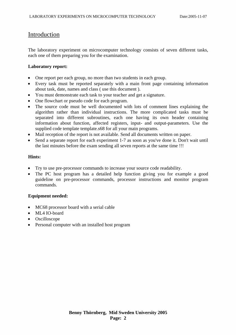
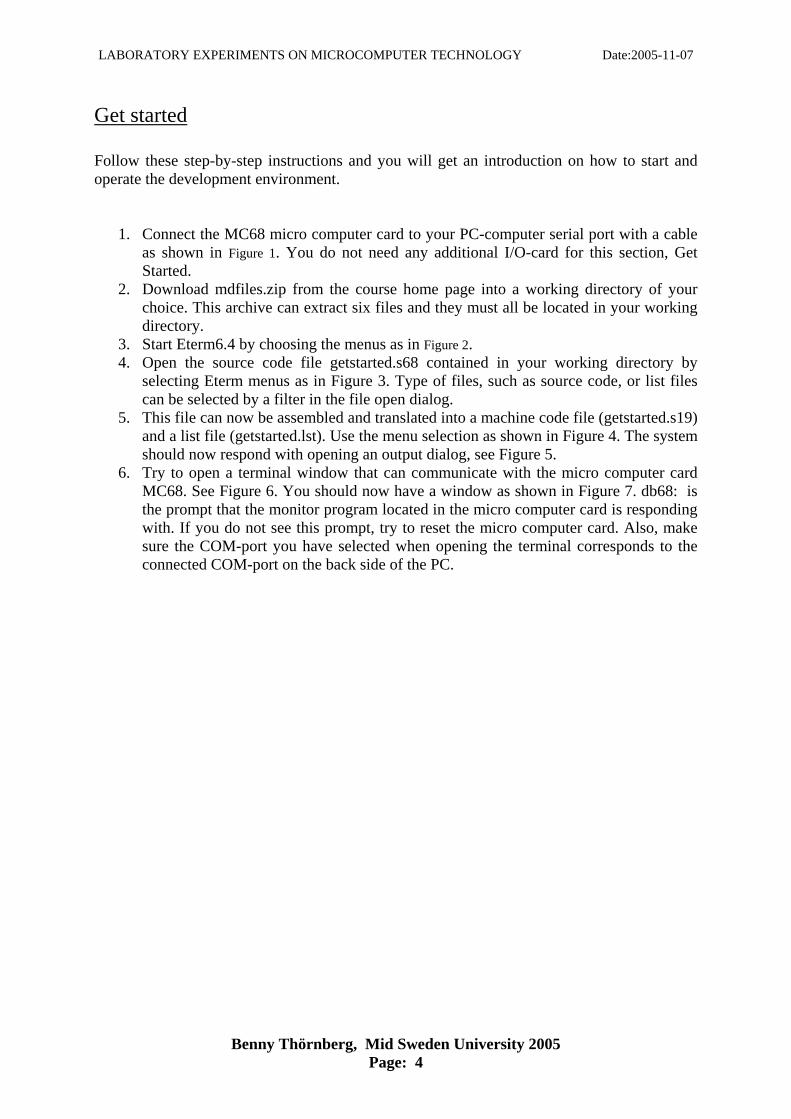
1. Connect the MC68 micro computer card to your PC-computer serial port with a cable
as shown in Figure 1. You do not need any additional I/O-card for this section, Get Started.
2. Download mdfiles.zip from the course home page into a working directory of your choice. This archive can extract six files and they must all be located in your working directory.
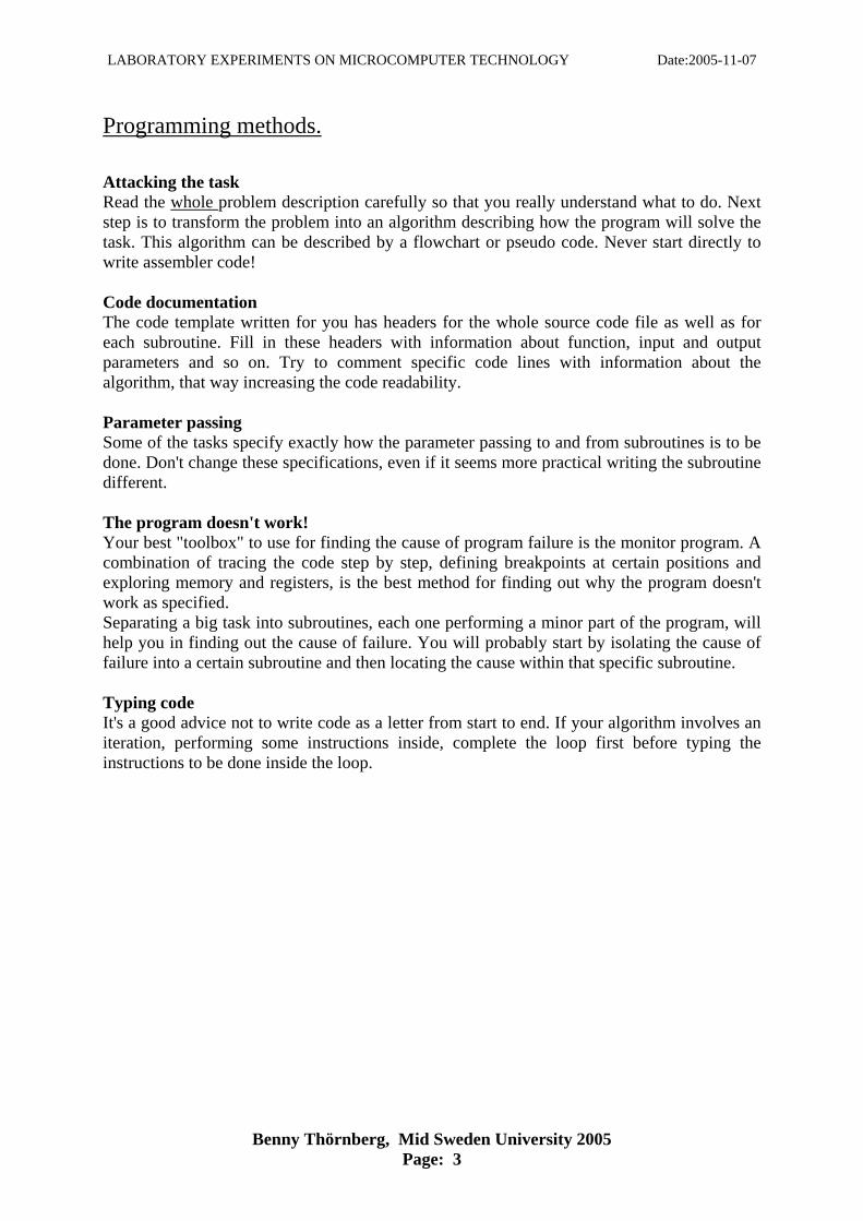
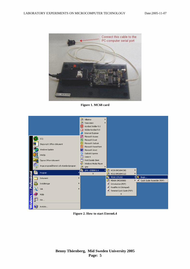
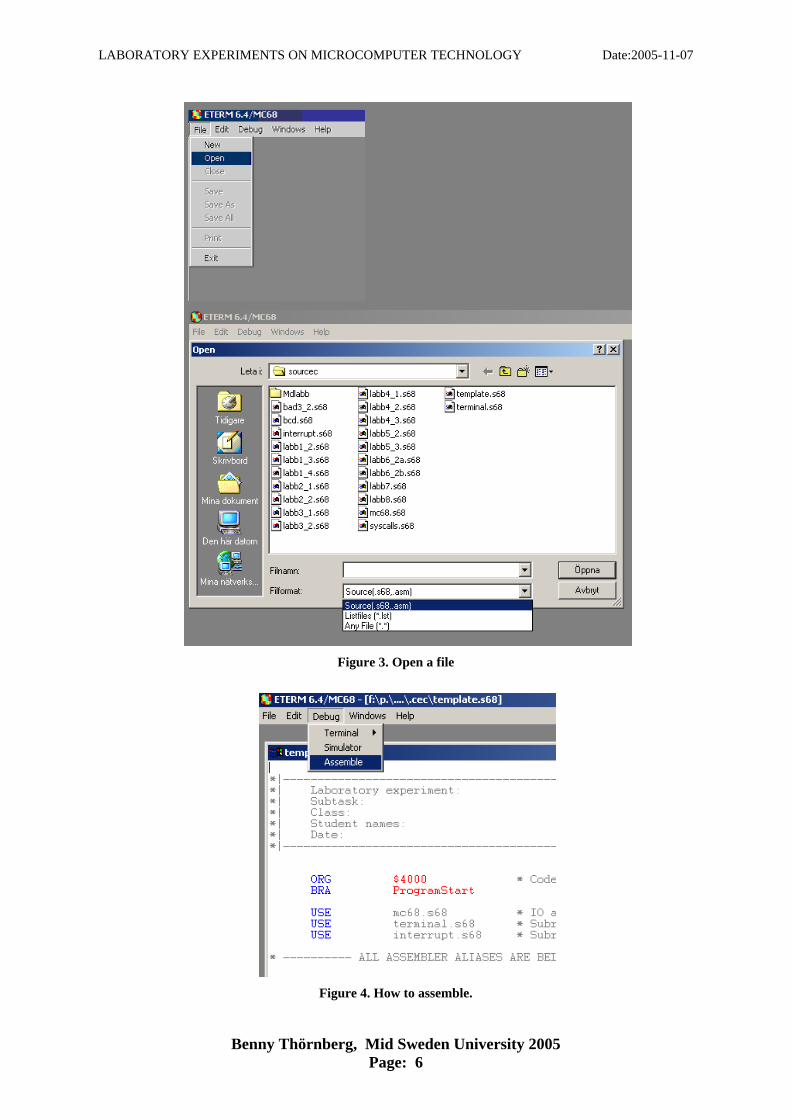
3. Start Eterm6.4 by choosing the menus as in Figure 2. 4. Open the source code file getstarted.s68 contained in your working directory by
selecting Eterm menus as in Figure 3. Type of files, such as source code, or list files can be selected by a filter in the file open dialog.
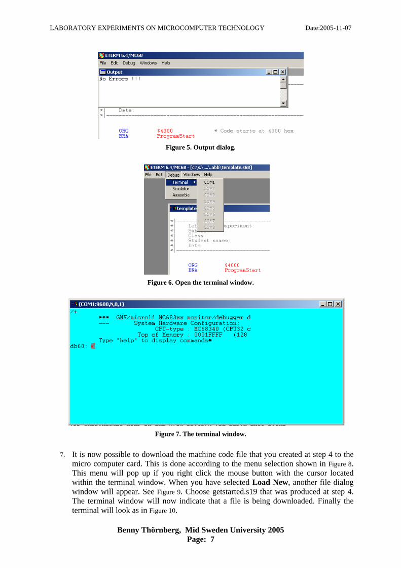
5. This file can now be assembled and translated into a machine code file (getstarted.s19) and a list file (getstarted.lst). Use the menu selection as shown in Figure 4. The system should now respond with opening an output dialog, see Figure 5.
6. Try to open a terminal window that can communicate with the micro computer card MC68. See Figure 6. You should now have a window as shown in Figure 7. db68: is the prompt that the monitor program located in the micro computer card is responding with. If you do not see this prompt, try to reset the micro computer card. Also, make sure the COM-port you have selected when opening the terminal corresponds to the connected COM-port on the back side of the PC.
LABORATORY EXPERIMENTS ON MICROCOMPUTER TECHNOLOGY Date:2005-11-07
Benny Thörnberg, Mid Sweden University 2005 Page: 5
Figure 1. MC68 card
Figure 2. How to start Eterm6.4
LABORATORY EXPERIMENTS ON MICROCOMPUTER TECHNOLOGY Date:2005-11-07
Benny Thörnberg, Mid Sweden University 2005 Page: 6
Figure 3. Open a file
Figure 4. How to assemble.
LABORATORY EXPERIMENTS ON MICROCOMPUTER TECHNOLOGY Date:2005-11-07
Benny Thörnberg, Mid Sweden University 2005 Page: 7
Figure 5. Output dialog.
Figure 6. Open the terminal window.
Figure 7. The terminal window.
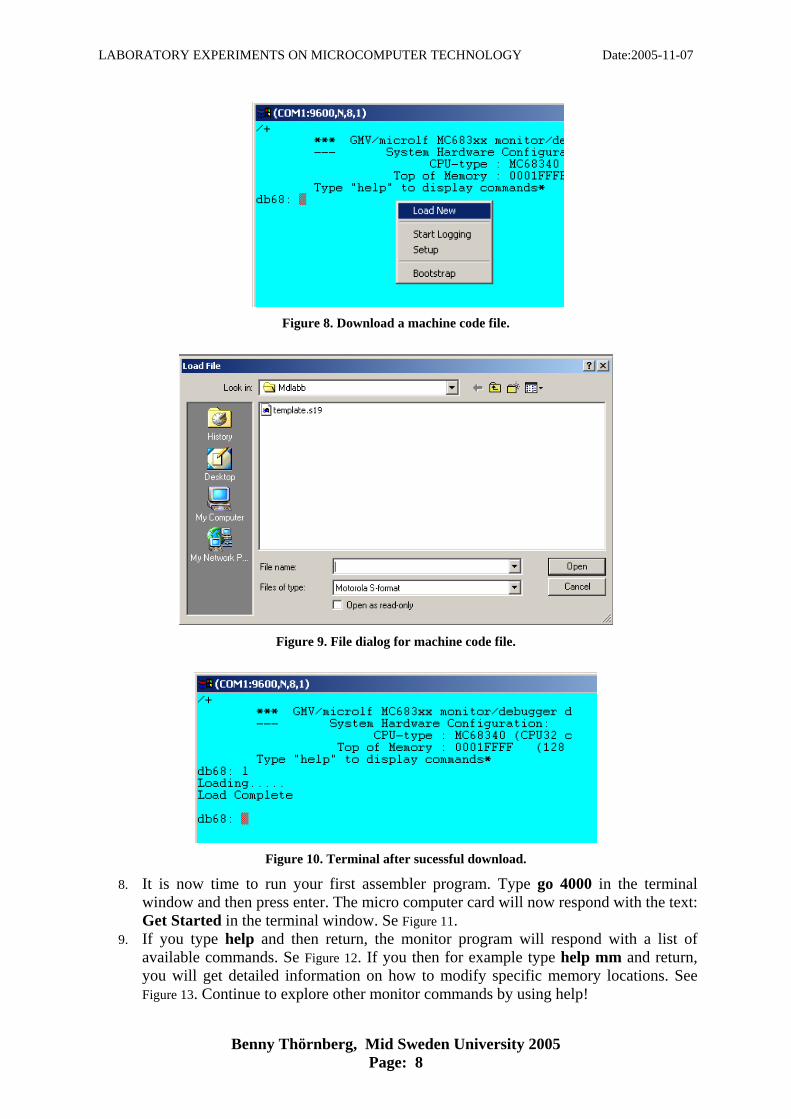
7. It is now possible to download the machine code file that you created at step 4 to the
micro computer card. This is done according to the menu selection shown in Figure 8. This menu will pop up if you right click the mouse button with the cursor located within the terminal window. When you have selected Load New, another file dialog window will appear. See Figure 9. Choose getstarted.s19 that was produced at step 4. The terminal window will now indicate that a file is being downloaded. Finally the terminal will look as in Figure 10.
LABORATORY EXPERIMENTS ON MICROCOMPUTER TECHNOLOGY Date:2005-11-07
Benny Thörnberg, Mid Sweden University 2005 Page: 8
Figure 8. Download a machine code file.
Figure 9. File dialog for machine code file.
Figure 10. Terminal after sucessful download.
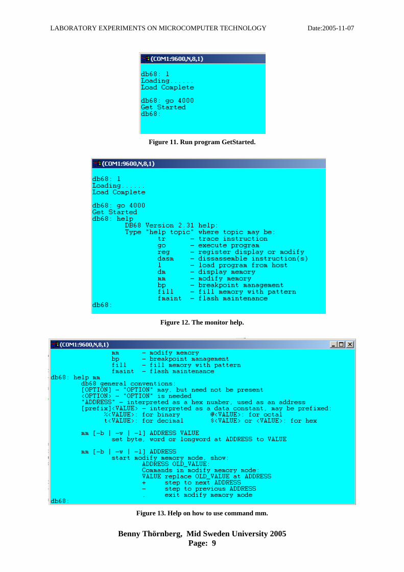
8. It is now time to run your first assembler program. Type go 4000 in the terminal window and then press enter. The micro computer card will now respond with the text: Get Started in the terminal window. Se Figure 11.
9. If you type help and then return, the monitor program will respond with a list of available commands. Se Figure 12. If you then for example type help mm and return, you will get detailed information on how to modify specific memory locations. See Figure 13. Continue to explore other monitor commands by using help!
LABORATORY EXPERIMENTS ON MICROCOMPUTER TECHNOLOGY Date:2005-11-07
Benny Thörnberg, Mid Sweden University 2005 Page: 9
Figure 11. Run program GetStarted.
Figure 12. The monitor help.
Figure 13. Help on how to use command mm.
LABORATORY EXPERIMENTS ON MICROCOMPUTER TECHNOLOGY Date:2005-11-07
Benny Thörnberg, Mid Sweden University 2005 Page: 10
Laboratory experiment 1. The very first experience Objective This task is your first taste of the assembly language, giving you some experience in two out of fourteen addressing modes, numerical representation and calculations. Task The previous section, Get started, will give you a quick overview of the development system. Follow the instructions in Get started before doing this first experiment. In this task, input- and output-parameters must be loaded and observed by using the monitor program. This means that you have to follow a certain workflow.
1. Write the assembly program and assemble it. 2. Open the list-file that was generated by the assembly process. Find out the exact
address of your input and output variables. 3. Download the executable machine code to the micro computer card. 4. Assign values to the memory locations reserved for your input variables using the
monitor program. 5. Run your application program 6. Explore the values of the output variables using the monitor program
Only the MC68 processor board is to be used for Laboratory experiment 1.
LABORATORY EXPERIMENTS ON MICROCOMPUTER TECHNOLOGY Date:2005-11-07
Benny Thörnberg, Mid Sweden University 2005 Page: 11
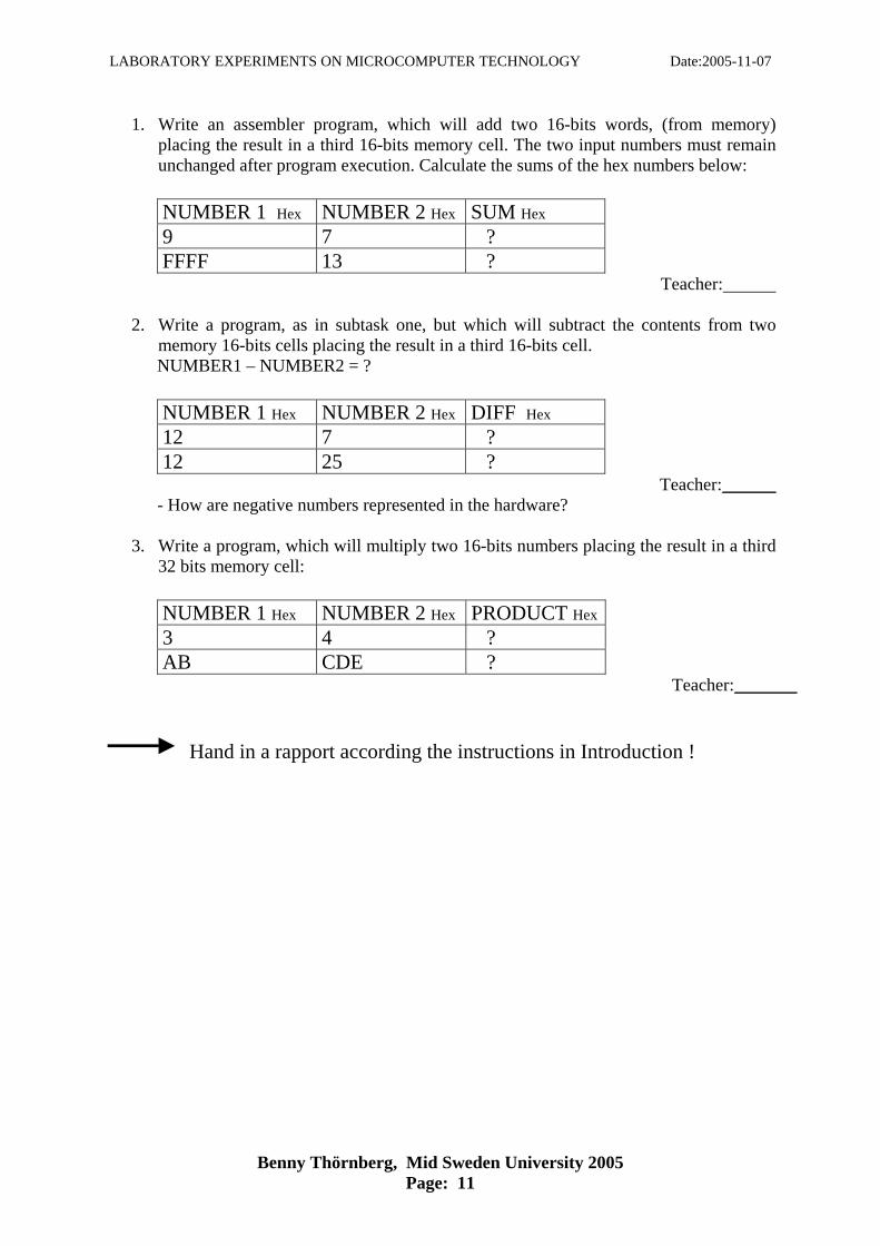
1. Write an assembler program, which will add two 16-bits words, (from memory) placing the result in a third 16-bits memory cell. The two input numbers must remain unchanged after program execution. Calculate the sums of the hex numbers below:
NUMBER 1 Hex NUMBER 2 Hex SUM Hex
9 7 ? FFFF 13 ?
Teacher:
2. Write a program, as in subtask one, but which will subtract the contents from two memory 16-bits cells placing the result in a third 16-bits cell.
NUMBER1 – NUMBER2 = ?
NUMBER 1 Hex NUMBER 2 Hex DIFF Hex
12 7 ? 12 25 ?
Teacher: ______ - How are negative numbers represented in the hardware?
3. Write a program, which will multiply two 16-bits numbers placing the result in a third 32 bits memory cell:
NUMBER 1 Hex NUMBER 2 Hex PRODUCT Hex
3 4 ? AB CDE ?
Teacher: _______ Hand in a rapport according the instructions in Introduction !
LABORATORY EXPERIMENTS ON MICROCOMPUTER TECHNOLOGY Date:2005-11-07
Benny Thörnberg, Mid Sweden University 2005 Page: 12
Laboratory experiment 2. Iterations Objective
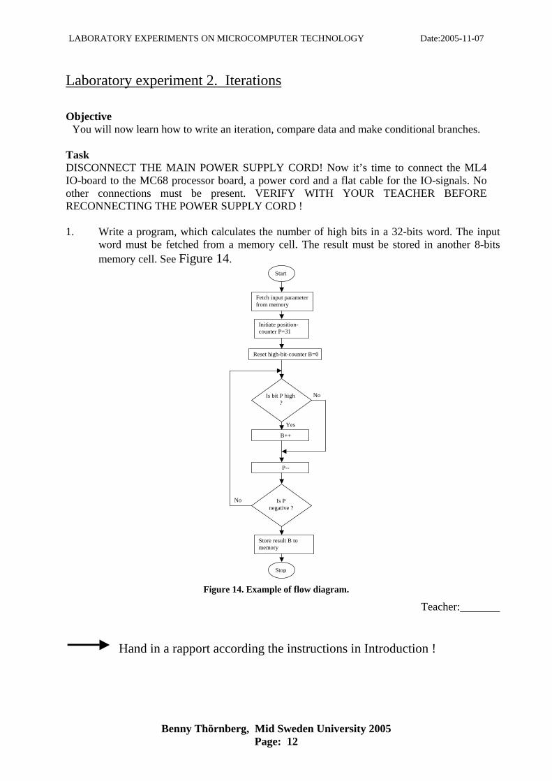
You will now learn how to write an iteration, compare data and make conditional branches. Task DISCONNECT THE MAIN POWER SUPPLY CORD! Now it’s time to connect the ML4 IO-board to the MC68 processor board, a power cord and a flat cable for the IO-signals. No other connections must be present. VERIFY WITH YOUR TEACHER BEFORE RECONNECTING THE POWER SUPPLY CORD ! 1. Write a program, which calculates the number of high bits in a 32-bits word. The input
word must be fetched from a memory cell. The result must be stored in another 8-bits memory cell. See Figure 14.
Start
Fetch input parameter from memory
Initiate position- counter P=31
Reset high-bit-counter B=0
Is bit P high?
B++
P--
No
Is P negative ?
No
Store result B to memory
Stop
Yes
Figure 14. Example of flow diagram.
Teacher: Hand in a rapport according the instructions in Introduction !
LABORATORY EXPERIMENTS ON MICROCOMPUTER TECHNOLOGY Date:2005-11-07
Benny Thörnberg, Mid Sweden University 2005 Page: 13
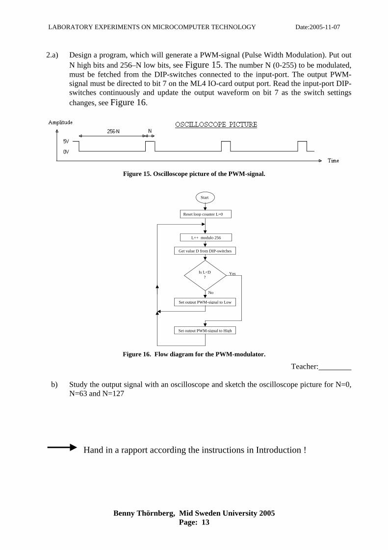
2.a) Design a program, which will generate a PWM-signal (Pulse Width Modulation). Put out N high bits and 256–N low bits, see Figure 15. The number N (0-255) to be modulated, must be fetched from the DIP-switches connected to the input-port. The output PWM-signal must be directed to bit 7 on the ML4 IO-card output port. Read the input-port DIP-switches continuously and update the output waveform on bit 7 as the switch settings changes, see Figure 16.
Figure 15. Oscilloscope picture of the PWM-signal.
Start
Reset loop counter L=0
L++ modulo 256
Is L<D ?
Get value D from DIP-switches
Set output PWM-signal to Low
Set output PWM-signal to High
Yes
No
Figure 16. Flow diagram for the PWM-modulator.
Teacher:
b) Study the output signal with an oscilloscope and sketch the oscilloscope picture for N=0, N=63 and N=127
Hand in a rapport according the instructions in Introduction !

LABORATORY EXPERIMENTS ON MICROCOMPUTER TECHNOLOGY Date:2005-11-07
Benny Thörnberg, Mid Sweden University 2005 Page: 14
Laboratory experiment 3. Subroutines Objective This will be your first acquaintance with subprograms and one mechanism to pass parameters between the calling program and the subprogram. Task DISCONNECT THE MAIN POWER SUPPLY CORD! Connect the ML4 IO-board to the MC68 processor board with a flat cable and a power cord. Connect a flat cable from the DIP-switch module to the input port B. 1. Write a subroutine, which gives a delay in milliseconds corresponding to the number
read from D3, ( parameter must be passed through D3 by value ) using a counter. Write a main program, which alternates the status of bit 7 on the IO-board output port. The delay between each alternation must be fetched continuously from the in-port DIP-switches and passed on to the subroutine as an input-parameter through D3. Use an oscilloscope to find the right counter value that will correspond to the selected delay. Guess the counter value and then adjust it according to the actual delay value observed on the oscilloscope. No registers (except CCR) must be affected after a call to your subroutine.
Teacher:
2. Write a program, which counts modulo 16, the number of switch alternations on a switch connected to input port, bit 0. Debouncing, means suppressing the narrow spikes as in the figure below but keeping the main pulses. Make use of the delay subroutine in subtask 1 to debounce the switch. You are not allowed to change the delay subroutine in any way! The counter must be sensitive only to bit 0! Counting must be done on high-to-low transition. The counter value must continuously be written to output port A and to be observed on the LED-bars.
Teacher:
Hand in a rapport according the instructions in Introduction !
LABORATORY EXPERIMENTS ON MICROCOMPUTER TECHNOLOGY Date:2005-11-07
Benny Thörnberg, Mid Sweden University 2005 Page: 15
Laboratory experiment 4. BCD - numbers. Objective This task will give you an understanding how a complex algorithm can be divided into separate subroutines that way increasing the source code readability. Subprograms can be seen upon as components made for possible reuse. Task Only the MC68 main board, connected to the PC, is to be used in this experiment. The monitor program must be used to pass input- and output-data to and from the programs. 1. Write a subroutine, which will convert a binary coded 16 bits word read from
register D0, into a Binary Coded Decimal number stored as 32 bits in register D1. Only register D1 (except CCR) must be affected after a call to your subroutine. Write a main program, which will call your subroutine once converting a number stored in one memory location to another. The main program must pass input and output parameters to and from the subroutine as described above. Hint:
65 535/10 000 = 6 , 5535 5 535/ 1000 = 5 , 535 535/100 = 5 , 35 35/10 = 3 , 5
Teacher:
2. Write a subroutine, which will type eight decimal digits, 0-9, read from register D0 (in BCD format) to the PC-screen. No registers (except CCR) must be affected after a call to your subroutine. Make use of the supplied subroutine WriteTTY contained in file terminal.s68. You will find information on how to use WriteTTY in its header. The characters will then appear in the Eterm terminal window. Write a main program, which will read eight BCD digits from a memory location and type them to the PC-screen. Zero must be typed as 0, (not 00000000) and eight must be typed as 8, (not 00000008). Parameter passing according to the specification above must be used! Hint: You’ll need to convert every digit into an ASCII character!
Teacher:
3. Write a subroutine, which will type a binary coded number to the PC screen displayed decimal and at the beginning of a new line. The number is the only parameter and must be read from the stack, passed by value. Use the subroutines you’ve just written in subtask 1 and 2, you are not allowed to change them in any way. No registers (except CCR) must be affected after a call to your subroutine! Write a main program, which will read a 16 bits binary coded number from a memory location and type it to the PC-screen. Hint: Use the subroutine NewLineTTY supplied by the terminal.s68 file.
Teacher:
Hand in a rapport according the instructions in Introduction !
LABORATORY EXPERIMENTS ON MICROCOMPUTER TECHNOLOGY Date:2005-11-07
Benny Thörnberg, Mid Sweden University 2005 Page: 16
Laboratory experiment 5. Stepping motor Objective This task will give you an example on how a small microcomputer system can be assigned a certain task as in this case, running a stepping motor and at the same time watching the keyboard for commands. This kind of application is typical for a so called embedded system. Task Read chapter 8 in– The students manual for ML4 lab card. (STUDIEHANDBOK FÖR LABORATIONER MED ML4) and learn how the stepping motor works and can be run. DISCONNECT THE MAIN POWER SUPPLY CORD! Connect the motor phases according to the table below:
Phases Output port A Red Bit 7 Blue Bit 6 Yellow Bit 5 White Bit 4
Reconnect the main power supply cord.
1.a) Define the four states that need to be written out to the output port A to run the stepping motor.
b) Run the stepping motor step by step using the monitor program, that way verifying your definitions in subtask a.
2. Write a program, which will run the stepping motor clockwise. A time delay
subroutine of approximately 15 ms must be called between each motor state. (Experiment 3, subtask 1, don't change the subroutine) You must be able to exit the program by pressing the ESC-key. Hint: Use subroutine ReadTTY contained in file terminal.s68.
Teacher:
3. Connect the photo-switch output to the input port B, bit 0. (The DIP-switches need to be connected as well, set switch 0 to ON, Your teacher can explain why! ) Add a counter to the program in subtask 2, which will count modulo 256, the number of motor rotations and type the result on the PC-screen at every rotation, using your subroutine written in experiment 4-3 ( don't change the subroutine from 4-3!) The counting and typing of the counter must be separated into a subroutine. The photo-switch rotation detection must be done using a polling method, detecting the flank, not level sensitive. Polling = repetitive status checking.
Teacher: Hand in a rapport according the instructions in Introduction !

LABORATORY EXPERIMENTS ON MICROCOMPUTER TECHNOLOGY Date:2005-11-07
Benny Thörnberg, Mid Sweden University 2005 Page: 17
Laboratory experiment 6. Interrupt. Objective A programming technique where an external event forces the processor into executing a corresponding service routine is often used in microcomputer systems. Watching for the occurrence of such an event can of course be done by a polling method where the software frequently checks if a specific event has occurred. A more efficient implementation is when a physical signal asynchronously, through some hardware interfacing logic, has the possibility to abort current program execution and start the execution of a service routine. In this task you will learn how to implement such an interrupt service routine. Task Connect your hardware as in experiment 5 with the only difference: The photo-switch output must be connected to the timer2 input labelled TGATE2 on the board. Restudy experiment 5, subtask 3. The photo-switch detection was done using a polling method. Now you must do the same experiment again but rather use an interrupt method for detecting and counting the motor rotations. A subroutine for enabling the timer 2 gate interrupt is supplied for you in file interrupt.s68. This file is invoked by the template with the directive USE. The input parameter of the subroutine EnableTimerInt is the pointer to the interrupt service routine you are just about to write - read more in the subroutine header. Another subroutine for clearing the timer interrupt flags is also supplied for you. 1. Write an interrupt service routine performing the desired motor rotation counting
modulo 256. Include this interrupt handling in the source code of experiment 5, exchanging the photo-switch polling. Do not use CPU-registers for parameter passing to your interrupt service routine!
Teacher:
2. What is the major difference between an interrupt service routine and a subroutine
call, as it comes to program flow? 3. How does this difference indeed impact the way you must write an interrupt service
routine as it comes to entering and exiting?
Hand in a rapport according the instructions in Introduction !
LABORATORY EXPERIMENTS ON MICROCOMPUTER TECHNOLOGY Date:2005-11-07
Benny Thörnberg, Mid Sweden University 2005 Page: 18
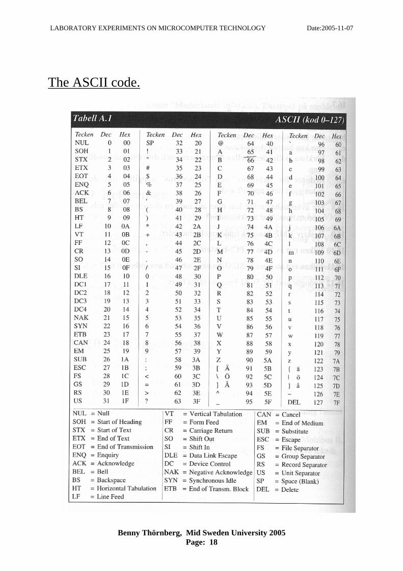
The ASCII code.