lab will start tomorrow
TRANSCRIPT
Lab will start tomorrow Everyone needs to check out 1 Raspberry Pi kit
Device connections in lab room
Lab 1 will be announced today One week turn-around time
1
Recap from last class I/O programming Memory-mapped I/O vs. special-purpose I/O instructions Busy-wait is simplest but very inefficient
• Devices are usually slower than CPU
Interrupts Using buffer to allow input/output at different rates Priorities and vectors allow to handle multiple interrupts
2
ECE 1175 Embedded Systems Design
Practical I/O Interfaces
Wei Gao
3
Timers and Counters Very similar: a timer is incremented by a periodic signal; a counter is incremented by an asynchronous, occasional
signal.
Timeout or rollover causes interrupt.
4
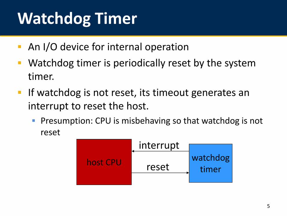
Watchdog Timer An I/O device for internal operation Watchdog timer is periodically reset by the system
timer. If watchdog is not reset, its timeout generates an
interrupt to reset the host. Presumption: CPU is misbehaving so that watchdog is not
reset
5
host CPU watchdogtimer
interrupt
reset
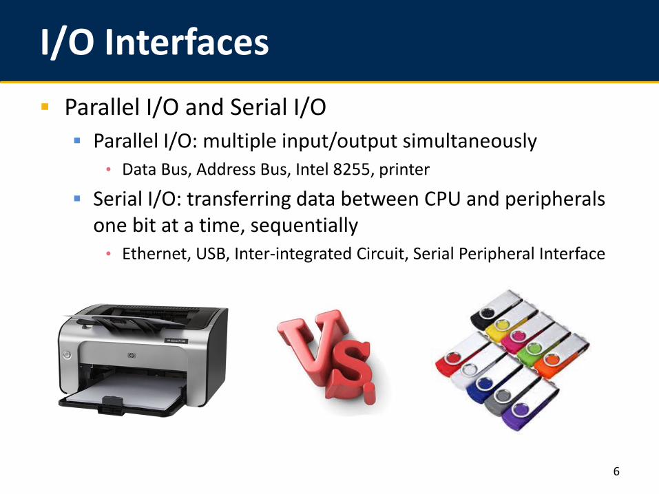
I/O Interfaces Parallel I/O and Serial I/O Parallel I/O: multiple input/output simultaneously
• Data Bus, Address Bus, Intel 8255, printer
Serial I/O: transferring data between CPU and peripherals one bit at a time, sequentially
• Ethernet, USB, Inter-integrated Circuit, Serial Peripheral Interface
6
I/O Interfaces Parallel v.s. Serial Parallel
• Wider bandwidth• More wires indicate more overhead• Simple I/O operation
Serial• 1-bit transfer per time unit• Less wires indicate less overhead• Complex I/O protocol
7
I/O Interfaces Serial over Parallel Parallel interfaces have less reliability
• Interference and noise corrupt data • Capacitance and mutual inductance affects bandwidth
Serial• Less mutual interference between wires • Higher clock frequency increases transmission rate
8
Inter-integrated Circuit (I2C) Inter-integrated Circuit (I2C or I2C) Two-wire interface Simple master/slave relationships No strict baud requirement and a
master generates a bus clock Each device is software-addressable
by a unique address
Philips semiconductors (now NXP)
9
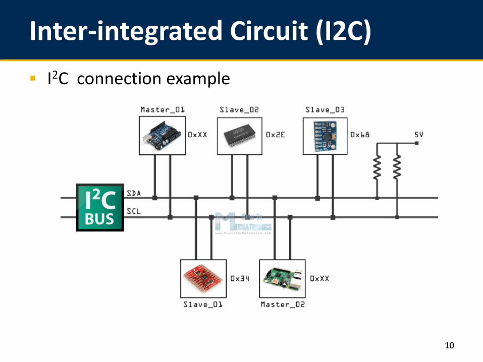
Inter-integrated Circuit (I2C) I2C connection example
10
Inter-integrated Circuit (I2C) I2C Terminology Master: sends out signals (clock signal and communication
signal) to slaves Slave: listens to the bus and waits to be addressed by
master Multi-master: I2C allows connections of multiple masters
Arbitration: decides which master to use wire
11
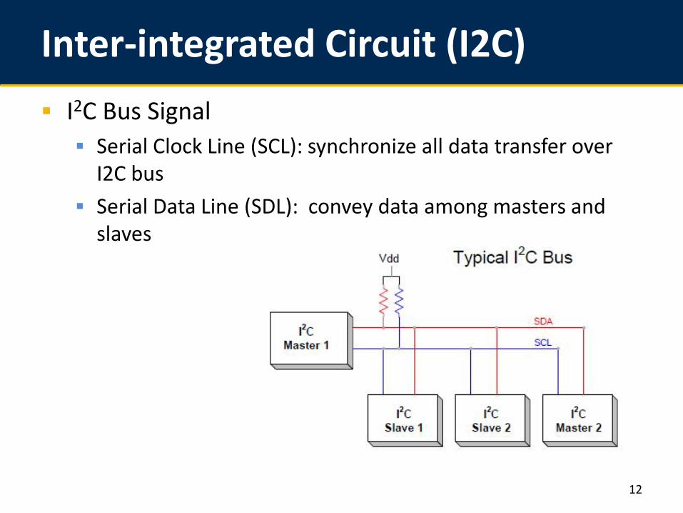
Inter-integrated Circuit (I2C) I2C Bus Signal Serial Clock Line (SCL): synchronize all data transfer over
I2C bus Serial Data Line (SDL): convey data among masters and
slaves
12
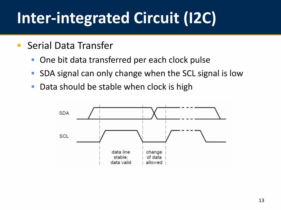
Inter-integrated Circuit (I2C) Serial Data Transfer One bit data transferred per each clock pulse SDA signal can only change when the SCL signal is low Data should be stable when clock is high
13
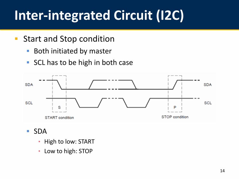
Inter-integrated Circuit (I2C) Start and Stop condition Both initiated by master SCL has to be high in both case
SDA• High to low: START • Low to high: STOP
14
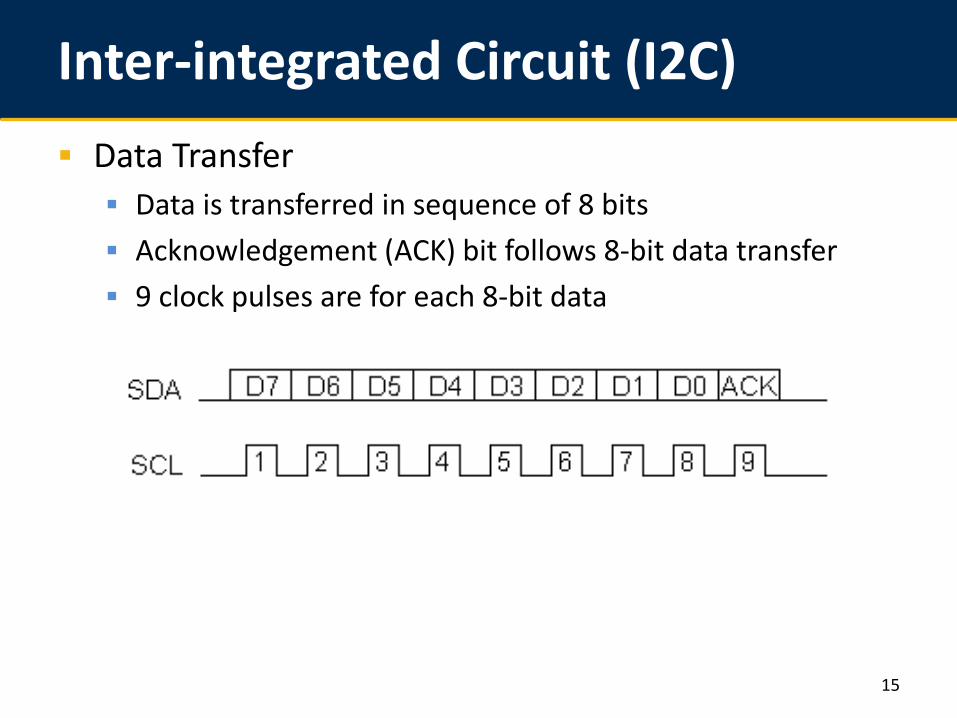
Inter-integrated Circuit (I2C) Data Transfer Data is transferred in sequence of 8 bits Acknowledgement (ACK) bit follows 8-bit data transfer 9 clock pulses are for each 8-bit data
15
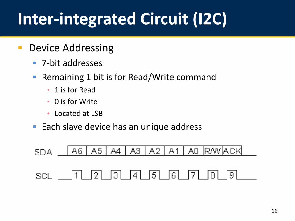
Inter-integrated Circuit (I2C) Device Addressing 7-bit addresses Remaining 1 bit is for Read/Write command
• 1 is for Read• 0 is for Write• Located at LSB
Each slave device has an unique address
16

Inter-integrated Circuit (I2C) Communication with 7-bit I2C Address
Initiating communication Addressing slave device Transferring data Ending communication
17
Inter-integrated Circuit (I2C) Smart phone Automotive Instrument Robotics Aerospace …
18
Serial Peripheral Interface (SPI) Serial Peripheral Interface (SPI) Serial protocol Peripheral connections in embedded system
• Microcontroller• EEPROMs• …
Quick communication over short distance Motorola
19
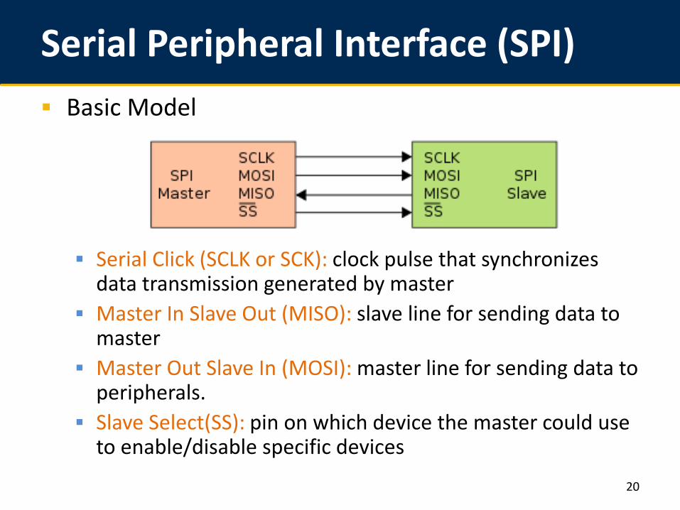
Serial Peripheral Interface (SPI) Basic Model
Serial Click (SCLK or SCK): clock pulse that synchronizes data transmission generated by master
Master In Slave Out (MISO): slave line for sending data to master
Master Out Slave In (MOSI): master line for sending data to peripherals.
Slave Select(SS): pin on which device the master could use to enable/disable specific devices
20
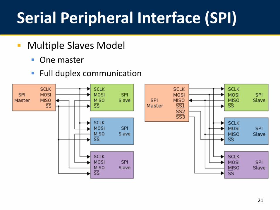
Serial Peripheral Interface (SPI) Multiple Slaves Model One master Full duplex communication
21
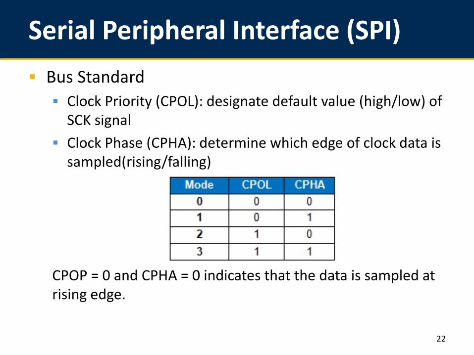
Serial Peripheral Interface (SPI) Bus Standard Clock Priority (CPOL): designate default value (high/low) of
SCK signal Clock Phase (CPHA): determine which edge of clock data is
sampled(rising/falling)
CPOP = 0 and CPHA = 0 indicates that the data is sampled at rising edge.
22
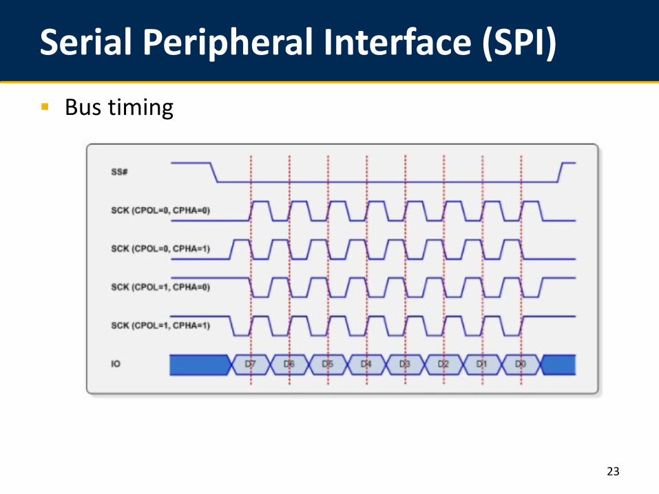
Serial Peripheral Interface (SPI) Bus timing
23
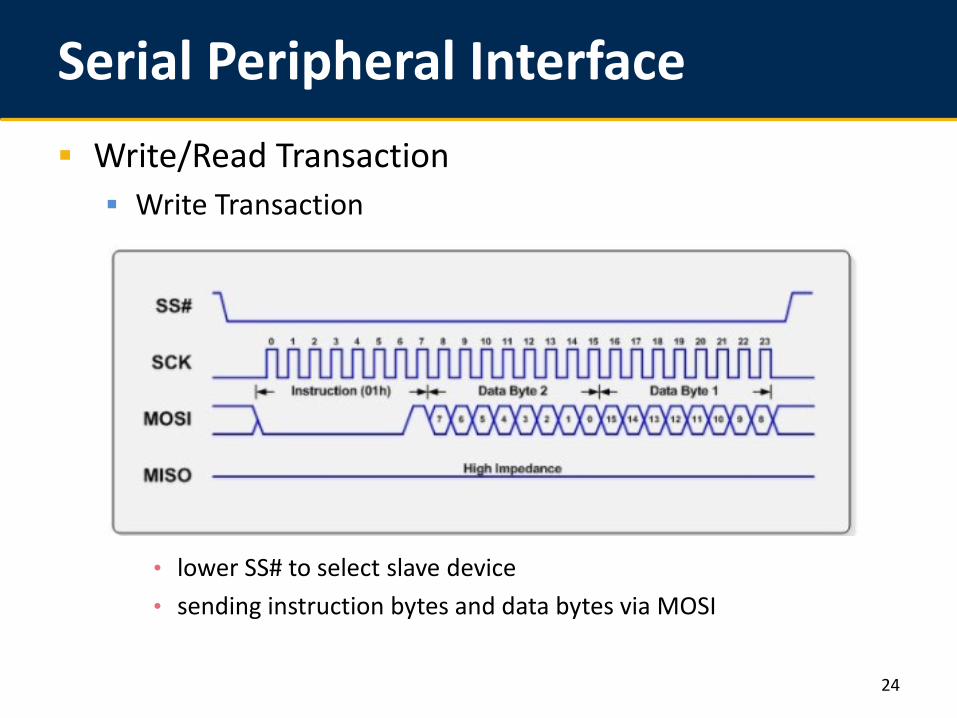
Serial Peripheral Interface Write/Read Transaction Write Transaction
• lower SS# to select slave device• sending instruction bytes and data bytes via MOSI
24
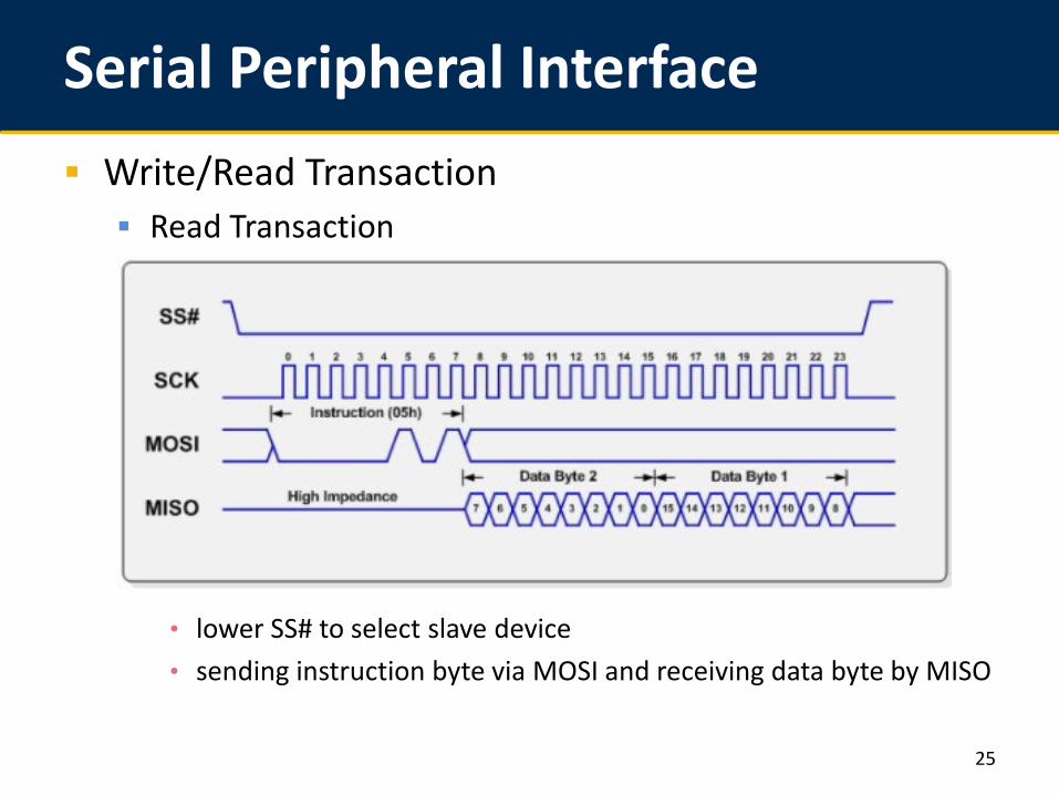
Serial Peripheral Interface Write/Read Transaction Read Transaction
• lower SS# to select slave device• sending instruction byte via MOSI and receiving data byte by MISO
25
SPI v.s. I2C Which one? I2C require two wires while SPI may need more SPI support full-duplex communication while I2C is slower I2C is more power-consuming than SPI I2C has ACK to verify data transfer while SPI is not I2C may have multiple master but SPI only has one master
26
SPI v.s. I2C SPI high speed and low consumption application faster
I2C large number of peripheral requirement and multiple
masters flexible
But both are robust protocols for embedded applications
27
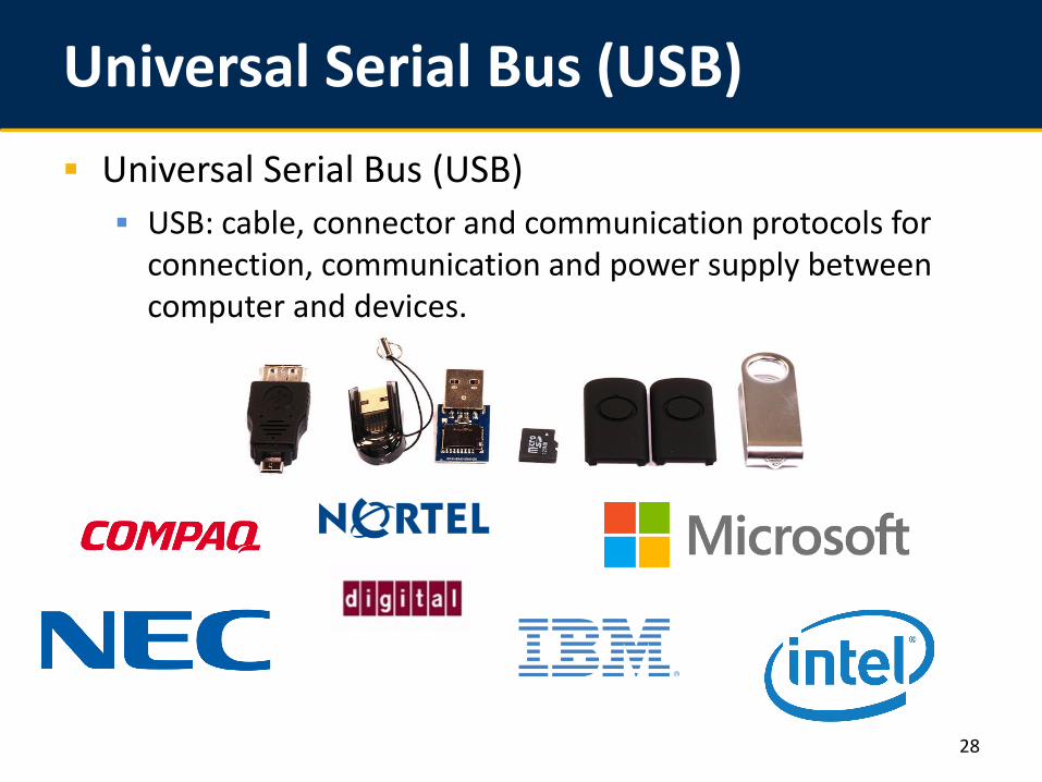
Universal Serial Bus (USB) Universal Serial Bus (USB) USB: cable, connector and communication protocols for
connection, communication and power supply between computer and devices.
28
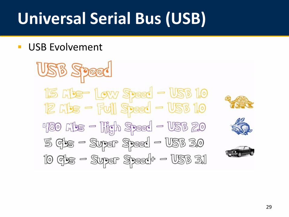
Universal Serial Bus (USB) USB Evolvement
29
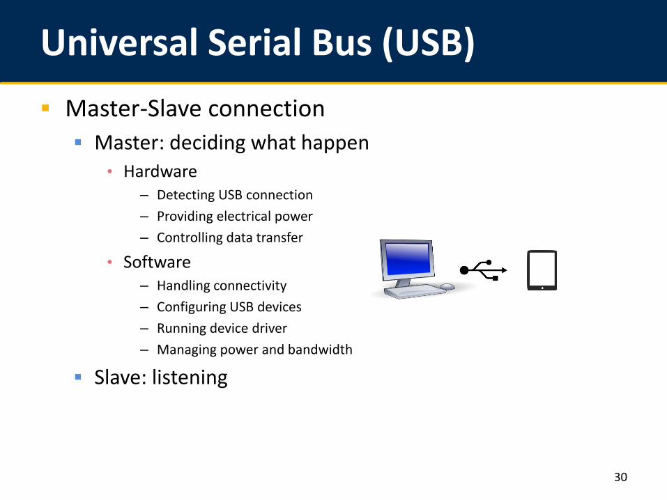
Universal Serial Bus (USB) Master-Slave connection Master: deciding what happen
• Hardware– Detecting USB connection– Providing electrical power– Controlling data transfer
• Software– Handling connectivity– Configuring USB devices– Running device driver– Managing power and bandwidth
Slave: listening
30
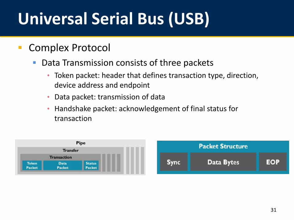
Universal Serial Bus (USB) Complex Protocol Data Transmission consists of three packets
• Token packet: header that defines transaction type, direction, device address and endpoint
• Data packet: transmission of data• Handshake packet: acknowledgement of final status for
transaction
31
Universal Serial Bus (USB) 4 Data Transfer Type Control transfer: exchange configuration, command
information between device and host Isochronous transfer: used by time-sensitive application
such as speaker, video camera Bulk transfer: used by scanners and printers that receive
data in one big packet and time is not crucial Interrupt transfer: used by peripherals which need
immediate attention from host
32
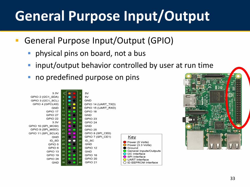
General Purpose Input/Output General Purpose Input/Output (GPIO) physical pins on board, not a bus input/output behavior controlled by user at run time no predefined purpose on pins
33
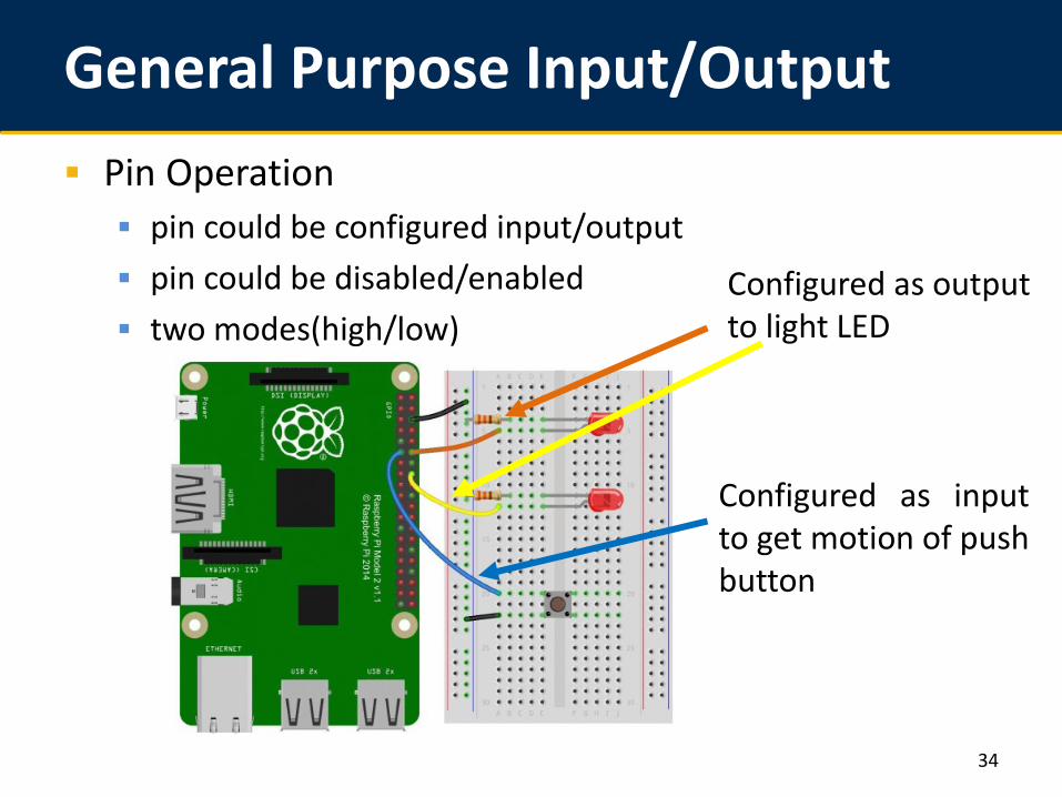
General Purpose Input/Output Pin Operation pin could be configured input/output pin could be disabled/enabled two modes(high/low)
34
Configured as output to light LED
Configured as inputto get motion of pushbutton
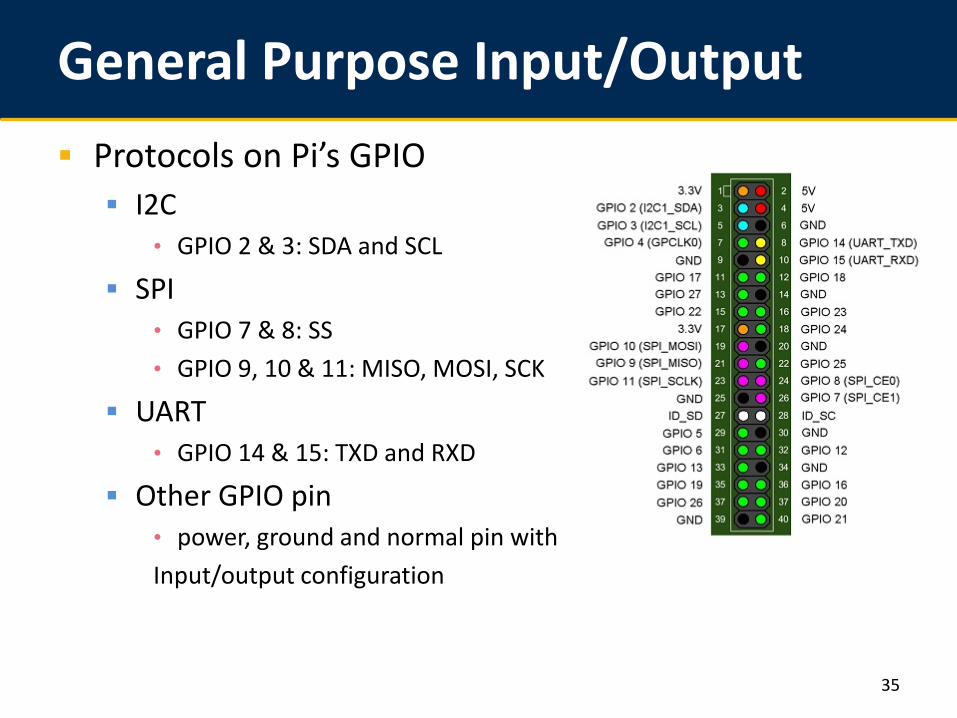
General Purpose Input/Output Protocols on Pi’s GPIO I2C
• GPIO 2 & 3: SDA and SCL
SPI• GPIO 7 & 8: SS• GPIO 9, 10 & 11: MISO, MOSI, SCK
UART• GPIO 14 & 15: TXD and RXD
Other GPIO pin• power, ground and normal pin withInput/output configuration
35
Lab 1
36
Lab 1 is due on 9/24 Everyone checks out one Raspberry Pi from the TA 6% in final grade Need to let the TA check you off
Warm-up with Raspberry Pi Basic Linux operations over the Pi Getting familiar and utilizing the pre-installed packages
• Graphics, sounds, etc…
http://www.pitt.edu/~weigao/ece1175/fall2021/lab1.htm