lab 6: lift and bernoulli - university of...
TRANSCRIPT

Lab 6: Lift and Bernoulli
Bio427 — Biomechanics
In this lab, we explore the flows and fluid dynamic forces on wingsand other structures. We deploy force measurement techniques, windmeters, and a variety of wind tunnels to measure these forces for arange of structures.
Figure 1: ’what quality of air surroundbirds in flight? The air surroundingthe bird is above thinner than the usualthinness of the other air, as below it isthicker than the same... in proportionto the velocity of the bird in its motionforward ...’ Sul volo degli Uccelli (On theflight of birds) Leonardo da Vinci 1500
Goals
• Construct a physical model of, or simulate, a prairie dog burrowand use this model to observe induced flow due to the Bernoulliprinciple.
• Understand and measure lift forces
• Explore shape, aspect ratio and camber for wings
• Examine how lift varies with the angle of attack of wings
Some useful constants for air at 20 C
• Density r = 1.2 kg m�3
• Dynamic viscosity µ = 1.9 ⇥ 10�5 Pa s
• Kinematic viscosity n = 1.5 ⇥ 10�5 m2s�1
Some useful constants for water at 20 C
• Density r = 1000 kg m�3
• Kinematic viscosity n = 1.0 ⇥ 10�6 m2s�1
Conceptual Basis
In this lab we will be examining two consequences of Bernoulli’sprinciple. One is the idea that pressure differences introduced byconservation of mass can induce flow in animal structures (e.g. gills,burrows) saving energy by using environmental flows. Similarly,pressure differences can lead to lift forces, allowing animals to propelthemselves in fluids.

lab 6: lift and bernoulli 2
Induced flow
In lecture, we introduced Bernoulli’s Principle as a fluid flow ver-sion of the law of energy conservation. Within some flow, the energyof a fluid particle with mass m moving along some streamline withvelocity u will be the sum of its kinetic energy (mu
2/2), gravitationalpotential energy (mgh), and the less familiar flow energy, which isequal to the work done by the fluid as it moves and equal to the fluidpressure on the particle multiplied by its volume (PV) or, equiva-lently, the fluid pressure multiplied by the particle mass and dividedby the fluid density (Pm/r). Bernoulli’s equation states that energymust be conserved for a fluid particle moving within a flow, and sothe sum of these three energies for that fluid particle must remainconstant:
mu
2
2+
Pm
r+ mgh = const. (1)
Typically in the analysis of fluid flows, however, we are often lessinterested in what happens to an individual particle within the fluidand more interested in characterizing the flow field. To this end, it istypically useful to rewrite Eqn. 1 by dividing both sides by V = m/r:
ru
2
2+ P + rgh = const. (2)
One critical assumption in Bernoulli’s principle is that the vis-cous forces acting on a fluid particle moving along a streamline canbe ignored, and so Eqn. 2 is only valid for fast moving flows whereviscous forces are minimal. A classic example from biology whereBernoulli’s principle applies is the construction of prairie dog bur-rows.
U↑P↓
U↓P↑
Induced Flow
Wind
Figure 2: Induced flow in prairie dogburrows.
The underground tunnels in which these animals live are con-stantly supplied with fresh air via induced air flow, which relies on apressure difference between the ends of the burrow to drive air flowthrough the tunnels. This pressure difference is achieved, as we willsee in this lab, by the physical structure of the burrow and how thisphysical structure affects the nature of the air flow moving across theentrances to the burrow.
Lift forces
Drag and lift forces arise when there is fluid motion relative to a sur-face. As we noted in class, drag follows from two types of stresses:viscous (shear) stresses and pressure (inertial) stresses. Togetherthose stresses constitute the total downstream force faced by an ob-ject moving relative to a fluid. Lift forces arise from an asymmetric

lab 6: lift and bernoulli 3
pressure distribution about an object and is, for our purposes here,defined as a force perpendicular to the direction of fluid motion. Ac-cording to the principal of continuity (conservation of mass), wesuggested that the flow over the top of a wing is faster than that be-neath the wing. And, according to Bernoulli’s principle that fasterflow is associated with a lower pressure above the wing than beneaththe wing. That pressure difference is one way to understand how liftis generated by an asymmetric objet in flow.
Predicting lift and drag forces on objects with complex shapesimmersed in fluids in which both density (r) and viscosity (µ) arecritical determinants of the flow is challenging and, in fact, thereare no analytic solutions to those forces. We turn instead to directmeasurements of lift (L) and drag (D) and their coefficients C
L
andC
D
respectively:
C
D
=2D
rSU
2 (3)
C
L
=2L
rSU
2 (4)
where U is the velocity of the fluid and S is the surface area of theobject. For objects like spheres, that surface area is the projected areaof the sphere (pr
2). For wings S is the planform area, which is thearea of the wing as you look down on it. In this lab, we will explorehow the lift force and its coefficient vary with the shape of a wing,it’s angle of attack and the wind speed.
Both lift and drag coefficients depend upon the Reynolds number(Re) of an object, the shape of the object (including its orientation inthe flow), and even its surface texture. Recall that the Reynolds num-ber measures the relative importance of inertial to viscous stresses:
Re =rUL
µ=
UL
n(5)
Figure 3: the span, chord length, angleof attack and camber of wings areshown for the most relevant studycreature of all: the hawkmoth Manduca
sexta
where n is the kinematic viscosity of the fluid and L is the charac-teristic length of an object. For spheres L is their diameter, for wingsit is their chord length.
Figure 4: Aspect ratios for a varietyof bird species adapted from OttoLilienthals study of brids as inspirationfor aircraft design
As mentioned above, the lift and drag coefficients depend upona host of parameters (e.g. Re and shape). For wings in particular,the aspect ratio, camber, and angle of attack a all strongly affect themagnitude of the lift coefficient. The angle of attack is defined as theangle of the wing with respect to the oncoming air. As you will seein this lab, increasing the aspect ratio increases the lift and, sadly, thedrag. For soaring and gliding animals it is helpful to hold the wingsat an angle of attack that maximizes the lift for a given drag.
Thus a vulture operating its wing at an angle of attack that has thegreatest lift for a given amount of drag, descends at the shallowest

lab 6: lift and bernoulli 4
angle possible. Importantly, very steep angles of attack can lead tothe formation of a significant wake behind the wing with massivedrag forces and, sadly, stall: the complete loss of lift. In this lab, youwill measure the relationship between lift and angle of attack for realwings. The aspect ratio (AR) of wings measures how long and thinthey are. For a rectangular wing, that aspect ratio is simply the spanof the wing (b) divided by the chord length (c). For wings with moreirregular shape we commonly define the aspect ratio as:
AR =b
2
S
(6)
where S is the surface (planform) area of the wing. You can verifythat for rectangular wings the aspect ratio is merely the span dividedby the chord.
Figure 5: Each curved line above iscalled a wing polar where increasingthe angle of attack increases the lift anddrag coefficients in a swift wing. Thelift and drag coefficients of swift wingsdepends on both the sweep angle ofthe wings (from 5 to 5 degrees) and theangle of attack (from -6 to 30 degrees).Lentink et al. Nature 446, 1082-1085(26April 2007)
Burrowing into the measurements
In this section of the lab, you will have two options: (1) you can builda physical model of a prairie dog burrow and (2) a computationalmodel using a simulator on an iPad.
For option 1 you will be constructing models of prairie dog bur-rows using cardboard, plastic tubing, and clay. Construct a burrowas shown in Figure 2 above. In the tunnel you have made, add somewater leaving the meniscus visible. We will be using the compressedair taps to provide a flow over the entrances to the burrow, and wewill restrict the orientations of the entrances to being perpendicularto the direction of the flow.
Place your burrow 2 inches from the exit of the air nozzle andslowly open the valve to the compressed air. When air passes overthe entrances to the model burrow, you will hopefully see the watercolumn in the tubing shift position. How does the change in watercolumn position relate to the pressure difference between the two en-trances? How does the pressure difference depend on burrow shape,relative height of the entrances, and relative size of the entranceholes?
For option 2, you will launch WindTunnel Pro on the iPads pro-vided. Use the following steps to create a simulation of the flow:
• Set the Parameters to default
• In the Interaction menu select Draw Wall
• Draw the geometry of interest
• In the interaciton menu select "draw smoke"
lab 6: lift and bernoulli 5
• In the Visualization menu select under the Physics sub-menueither Pressure or Speed
• Describe your results in the worksheet attached.
Measuring Lift
In this section of the lab, you will explore how both wing shape andangle of attack influences the lift generated by real wings. You will beequipped with a wing holder and materials for creating wings. Thewing holder mounts to a fixture that supports the wing and attachesto a very sensitive pan balance. The pan balance, in return, providesa direct measure of the change in vertical force. Note that the balancereports grams (which is not force – but a mass) so you will have toconvert to Newtons.
The wing mounting fixture has holes spaced every 15 degrees,from horizontal (0 degrees) to vertical (90 degrees). You can simplyrotate your wing for each angle and record the value on the panbalance. What angles of attack were most effective in generating lift?
If time permits, you can also draw a wing using the Wind Tunnelapp on the iPads. There you can actually estimate the lift generatedby sections of interest. This, however, is just a two dimensional simu-lation.
Exploring wings
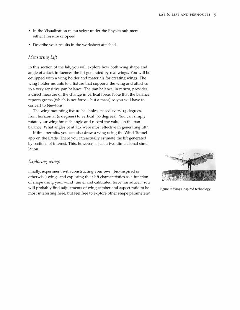
Figure 6: Wings inspired technology
Finally, experiment with constructing your own (bio-inspired orotherwise) wings and exploring their lift characteristics as a functionof shape using your wind tunnel and calibrated force transducer. Youwill probably find adjustments of wing camber and aspect ratio to bemost interesting here, but feel free to explore other shape parameters!

Lab 6: Lift and Bernoulli
Note: Hand in one worksheet per lab groupLab Section:Name 1: Name 2:
Some useful constants for air at 20 C
• Density ⇢ = 1.2 kgm�3
• Dynamic viscosity µ = 1.9⇥ 10�5 Pa s
• Kinematic viscosity ⌫ = 1.5⇥ 10�5 m2s�1
Some useful constants for water at 20 C
• Density ⇢ = 1000 kgm�3
• Kinematic viscosity ⌫ = 1.0⇥ 10�6 m2s�1
Prairie dog burrow
Draw a diagram of your model below.
What was the maximum pressure di↵erence between the entrances of the burrow that you were able toachieve? (The pressure di↵erence is
Given that pressure di↵erence, what is your predicted velocity di↵erence? (you will want to use Bernoulli’sHow did the shape of the entrance mounds a↵ect your pressure di↵erence?
How about the size of the burrow entrances?
How would you expect these parameters to a↵ect the pressure di↵erential, based on Bernoulli’s equation?

Lift on a wing
Angle of attack (�)
Lift(N
)
What angle of attack provided the highest lift from the wing?
Making wings
How did the performance of your constructed wing vary with aspect ratio and camber?
Choose one additional shape parameter and test how varying this shape parameter a↵ects the lift gener-ated by your wing. Describe your results below.
2