l' l-i£ y / 9' 6 f' ili,t 2 kt ' , . chapter 4
TRANSCRIPT

uo ",aves II warm plasma Chap. j
-,enhai/"'Cd for a relativistic plasma (Beard, 1959), Imre (1962) has con-, si 'ered 'the problem of electromagnetic wave propagation in relativisticplasmas in detaiL. As an example, he obtains for propagation along the
field, to first order in kT/mc2,
1- Wp 2 (1- 5w kTJ~ 2 "" w( W l Wb) 2( W l wb) mc2 (3 6 1)ILI,T"" 2 kT ' , .
1 + WWp _(w l Wb)3 mc2
which is to be compared with (3.4,13), Johnston (1962) has developed
weakly relativistic expansions, obtaining, for example, for electromagneticwaves in a plasma with no magnetic field
1- w/ (1-~ kT)¡i2 ~ w2 2 mc2 ~ i _ Wp 2 (1 + (~_ w/) kT),W 2 kT w2 2 w2 mc2
i +-L -w2 mc2
(3,6.2)
which is to be compared with (3.4,22),
2- -- l:= 7
i:'.-;.
J..............!i\'..i
"F/¡;...' i
.';
FIÛ l- Htí,4l-1t ~ L-N~T7..ø £,,4 __ '" l)( A-A/Osn ¿ 5 '-( L- aA L)(J('..A!;f'
"" l' l-i£ Y / 9' 6 f'
CHAPTER 4
Wave propagation through
bounded plasmas
4.1 Introduction
The preceding chapters have been concerned with the propagation ofelectromagnetic waves in an infinite plasma, We now consider the effectof plasma boundaries on the propagation, To study high-density dis-charges of arbitrary size and geometry, one is generally forced to usemicrowave beams directed through the plasma by means of suitableantenna systems. The alternative situation in which the plasma is locatedwithin a cavity or waveguide, or is itself a waveguide, is considered inChapter 5, The "free-space" beam technique is favorable where thedimensions of the plasma are larger than the wavelength of an electro-magnetic wave at the plasma frequency, Both classes of measurements
are essentially limited to frequencies w~wp, the plasma frequency (exceptfor special techniques exploiting a static magnetic field or a detailed
independent knowledge of the density profile). Thus, the beam techniqueis most readily analyzed when
2 J Wp 2 ,W))1.C/D)2, (4,1.)where D is the dimension of the plasma. The first of these two inde-pendent conditions permits convenient simplifications in the analysis byavoiding the plasma resonance; the second is essentially a diffractioncondition which permits reducing the problem of propagation of a finitebeam of electromagnetic waves through a finite plasma to a one-dimensional, plane-wave problem, as a first approximation.
The propagation constant of a microwave beam in a plasma has been117

.. ,w" p' "p..,...""" ."r""1!11 o""iiueu piusmas l.nap. 'I
,shown,H1Chapter 1, to depend upon the magnetic field, electron density,arid collision frequency, and indirectly upon the temperature, Thefollowing basic arrangements, sketched schematically in Fig, 4,1, are
useful in the case of high-temperature, highly ionized plasmas (that is,V((wp),
(1) Simple transmission or reflection, For electron densities n -: nc theplasma is transparent, while for n;: nc it is opaque and totally reflecting,where nc=(£omje2)w2 is the critical density.! The transition between
1 In the presence of a magnetic field, the effective critical deiisity may be altered.
However, the situation is qualitatively unchanged.
I Source i ~
Sou rce
,,'\W ~ I Detector I
l(a), Transmission
A\~l(b). Reflection
ll'W2, Phase shift
FIG. 4,1 Elementary microwave observation schemes.
i
";c"11'-";'"
òi.'-
4.1 Introduction 119
these conditions is sharp, Thus, in principle, this elementary technique
indicates whether the plasma density is above or below the critical value,Measurement at a given frequency is capRble of determining only one valueof density, The sharpness of the transition implied by the sudden change
in the attenuation coeffcient is not realized in practice because of the
following factors,
(a) For densities below but approaching critical, the dielectric constantdiscontinuity at a sharp boundary produces an increasingly strong surfacereflection (and corresponding reduction in transmission).
(b) If the plasma is only a few wavelengths thick, interference effectsoccur between the surface reflections,
(c) Inhomogeneous density distributions are not averaged in a simplemanner.
(d) Refraction and scattering by the plasma occur because of inade-
quacies in the one-dimensional, plane-wave approximation.
If the plasma density is far above critical, an impinging signal is stronglyreflected at the boundary, Therefore, motions of the effective boundaryproduce doppler shifts in the frequency of the reflected signaL.
(2) Phase shift (microwave bridge or interferometer), If the signal from
an auxiliary transmission path, with adjustable amplitude and phaseelements, is balanced against the primary transmission signal to give a nullin the absence of plasma, the output signal of the waveguide (hybrid) junc-tion is a measure of the attenuation and phase shift in the primary path dueto the plasma, In the fully transparent region of electron density, where
n((nc, a detected signal represents only phase shift which, in turn, isessentially a function of electron density only, Since the shift in phasecan be calibrated, one has a continuous measurement of density betweenthe upper limit of serious amplitude effects in the transmission path, andthe lower limit of detector sensitivity. This technique is ideally suited to theobservation of density as a function of time.
The propagation of the microwave beam through the bounded plasmais most readily analyzed in two limiting cases: first, the gradual boundary,with density varying slowly over a wavelength, to which an adiabaticanalysis may be applied; and, second, the sharp boundary which can beattacked as a boundary-value problem, A formally similar situationoccurs in quantum mechanics, in which the first case is known as theWKB approximation (Bohm, 1951). The usual geometrical optics limitpartakes of both the above limits. It neglects reflections at the "sharp"boundaries which separate -regions of different propagation characteristicsand, thus, can be self-consistent only for plasmas large compared to awavelength. The models of plasma geometry that are most useful for
124 Waiie propagation through bounded plasmas Chap. 44.2 Simple a.diabatic analysis of a plasma slab 125
Therefore_ 3 p2 f 2 . I 5 p3 f 3. .
¡JCPi - 2 ¡JCP2 - 32 cw3 n (x) dx + 256 cws n (.,) d.' + ' . . (4,2,13)
and we obtain for the first two averages of the distribution
!w f n dX=4n¡JCP2-~ (¡Jcpi-2¡JCP:i)) + 1~8 :~s f n3 dx+, ., rp2 f 32 f 15 p3 f Lcw3 n2 dx=-r L (¡JCPi-2¡JCP2)-256 cws n3 dx-". r
The usefulness of this approach is limited by the accuracy of the differential
measurement ¡JCPi - 2 ¡JCP2' When this quantity can be successfully
measured, (4,2,14) provides a refined evaluation of the average densityand (4,2.1 5) an estimate of the mean-square density,
Procedures for obtaining profile information have been developed byMotley and Heald (1959) and by Wharton and Slager (1960). Whartonand Slager use only the magnetic-field-independent parallel-polarizationcase. Their data-reduction procedure is to calibrate the peak electrondensity by means of the cutoff of a "low-frequency" wave, and obtaininformation from the simultaneously observed phase shift of a "high-frequency" wave, Motley and Heald, using different polarizations,calibrate the average density with the high-frequency wave, infer profiefrom the low-frequency wave. Because of the greater phase-shift non-linearity of the perpendicularly polarized wave near cyclotron resonance,the multiple polarization technique, when applicable, is somewhat moresensitive, The Wharton and Slager technique provides profile informa-tion only at the instants of time for which cutoff occurs; the Motley andHeald technique is limited to situations where the cyclotron frequency iscomparable to the plasma frequency and is accurately known, Bothmethods benefit from additional phase-shift data channels at otherfrequencies and/or polarizations, at the expense of instrumentation anddata-reduction complexity, Neither method is able to distinguish a hollowdischarge from a peaked one, Experimental applications of theseprinciples are discussed in Sections 6,4 and 6.5.
4.2.3 Reflections from cutoffs and resonances. Cutoffs, at which the
index of refraction ¡i -+ 0, and resonances, at which ¡i -+ 00, occur forcertain combinations of frequency, density, and magnetic field, When awave propagating in an inhomogeneous plasma impinges upon regionshaving these special characteristics, reflection and absorption must beconsidered even in the adiabatic approximation, Near the cutoff, thewavelength grows large, while near the resonance the wavelength becomessmall. In both cases, the group velocity goes to zero, The analysis of
this situation is formally identical to that resulting in the so-called turning-point connection formulas of the quantum-mechanical WKB approxima-tion (Schiff, 1955), It can be shown that in the case of a cutoff the wave is
(4,2,14)
however, we do not restrict our consideration to this first-order case, butstil retain the adiabatic approximation, we can (1) expand the ¡JcP integrand
to higher orders, in which case the integrals obtained are higher-order
averages of the distribution function (for example, f n2(x) dx); or (2)integrate ¡JcP directly using an appropriate distribution function,
In either case, a meaningful average electron density is not obtainedwithout an independent knowledge of the distribution function, since thephase shift is not linear with density, and the method becomes less usefulfor the quantitative measurement of even average densities. If, forexample, we assume a constant electron density (that is, a rectangularprofile which, incidentally, is somewhat contradictory to the adiabaticassumption), the integration is trivial, and we obtain a parabolic de-pendence of density on phase shift
~=2(~ ¡Jcp) _ (~¡Jcp)2. (4.2.10)no L 21T L 21T
Figure 4.3 is a universal graph of this relation,Since the phase shift introduced by the plasma sample is, in general, a
nonlinear function of electron density, we obtain information on thedistribution of density (profile) by making simultaneous measurements atdifferent frequencies and/or with different polarizations with respect to amagnetic field.
We can expand the integrand in (4.2,2) (assuming no magnetic field),
(4.2,15)
rL f ( (w )2)Y.'\ 21T¡JCP=Jo '\1- 1-: fTdx
rL (1 pn(x) 1 p2n2(X) 1 p3n3(X) 5 p4n4(X) ) w=Jo ï~+g~+16~+128~+'" ëdx,(4.2,11)
where p=e2/"om, Note that the series does not converge rapidly, As anexample, consider two measurement frequencies
Wi=W
w2=2w,for which1 f 12f i 3f¡JCPi =ï!w n(x) dX+g :w3 n2(x) dx+ 16 !WS n3(x) dx+. ..,1 f 12f 1 f¡JCP2=4 :w n(x) dx+ 64 :w3 n2(x) dx+ 512 c~s n3(x) dx+ . . ..
(4,2,12)
126 Wave propagation through bounded plasmas Chap. 4
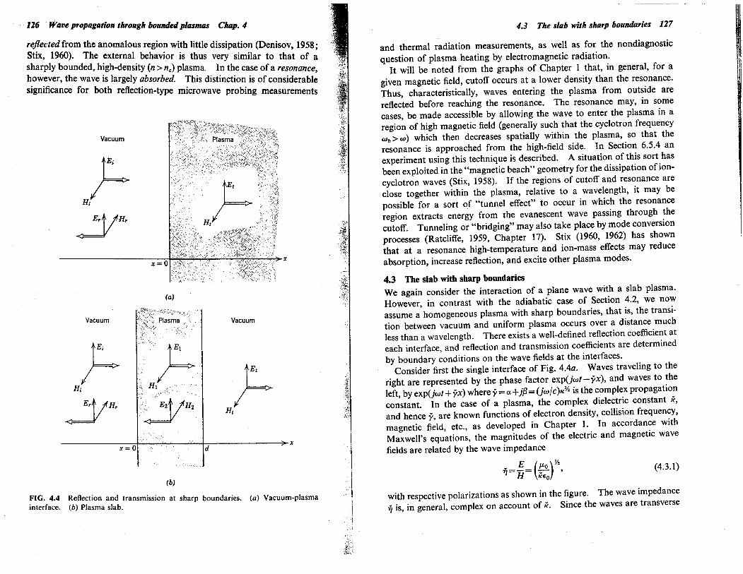
rejlectedfrom the anomalous region with little dissipation (Denisov, 1958;Stix, 1960), The external behavior is thus very similar to that of a
sharply bounded, high-density (n :; nc) plasma. In the case of a resonance,however, the wave is largely absorbed, This distinction is of considerablesignificance for both reflection-type microwave probing measurements
Vacuum
x
tEi .
H¡IYHr
(a)
Vacuum Vacuum
r;h E,HiErt lHr .'.:.'~:;:tIH' r~ ~ Hix
d
(b)
FIG, 4,4 Reflection and transmission at sharp boundaries. (a) Vacuum-plasma
interface. (h) Plasma slab.
43 The slab with sharp boundaries 127
and thermal radiation measurements, as well as for the nondiagnostic
question of plasma heating by electromagnetic radiation.It wil be noted from the graphs of Chapter i that, in general, for a
given magnetic field, cutoff occurs at a lower density than the resonance,Thus, characteristically, waves entering the plasma from outside arereflected before reaching the resonance. The resonance may, in somecases, be made accessible by allowing the wave to enter the plasma in a
region of high magnetic field (generally such that the cyclotron frequencyWb:; w) which then decreases spatially within the plasma, so that the
resonance is approached from the high-field side, In Section 6.5.4 anexperiment using this technique is described, A situation of this sort hasbeen exploited in the "magnetic beach" geometry for the dissipation of ion-cyclotron waves (Stix, 1958), If the regions of cutoff and resonance areclose together within the plasma, relative to a wavelength, it may bepossible for a sort of "tunnel effect" to occur in which the resonanceregion extracts energy from the evanescent wave passing through thecutoff, Tunneling or "bridging" may also take place by mode conversion
processes (Ratcliffe, 1959, Chapter 17), Stix (1960, 1962) has shownthat at a resonance high-temperature and ion-mass effects may reduce
absorption, increase reflection, and excite other plasma modes,
4.3 The slab with sharp boundaries
We again consider the interaction of a plane wave with a slab plasma,However, in contrast with the adiabatic case of Section 4.2, we nowassume a homogeneous plasma with sharp boundaries, that is, the transi-tion between vacuum and uniform plasma occurs over a distance muchless than a wavelength. There exists a well-defined reflection coeffcient ateach interface, and reflection and transmission coeffcients are determinedby boundary conditions on the wave fields at the interfaces,
Consider first the single interface of Fig, 4.4a, Waves traveling to theright are represented by the phase factor exp(jwt-yx), and waves to theleft, by exp(jwt + yx) where y = a + jß = (jWlC)K'I is the complex propagationconstant. In the case of a plasma, the complex dielectric constant re,and hence y, are known functions of electron density, collision frequency,magnetic field, etc., as developed in Chapter 1, In accordance withMaxwell's equations, the magnitudes of the electric and magnetic wavefields are related by the wave impedance
E ( )Y:ií = ii = :eoo ' (4.3.1)
with respective polarizations as shown in the figure. The wave impedanceií is, in general, complex on account of re, Since the waves are transverse

128 Wave propagation through bounded plasmas Clup. 4
and there are no surface currents at the interface, the boundary conditionsrequire that E and H are continuous across the interface. Therefore thewave amplitudes, in the notation of Fig, 4.4a, are related by
E¡+Er=Ei
E¡-Er=j(YoEi, (4,3.2)
It follows that the (complex) amplitude reflection and transmission
coeffcients are, respectively,
~ Er 1-j(Yo rí-'Iop-------'- EI-1 +j(Yo - rí+'Io
_ Ei 2 2rí'r=-=--=_; (4.3,3)E¡ 1 + KYo 'I + '10
where '10 = 377 ohms.is the wave impedance of free space, Note thesignificance of the wave impedance that there is no reflection when theimpedances of the two media are equa1.2
The single-interface power reflection and transmission coeffcients are,respectively,
_ (1-¡i)2+X2r= Ip12= (1 + ¡i)2+X2'
1 I ~12 4¡it= -r=¡i T =(1 )2. 2+¡i +X
where ¡i-jx=j(Yo= -fycfw, and the voltage standing-wave ratio is3
(4,3.4)
VSWR= 1 + Ipl_1 +r%l-Ipl-l-r%' (4,3.5)
2 In a more general (nonplasma) case with the relative permeabilty Km different from
unity and perhaps also complex, then r¡ = (KmP.o/K£o)~~' Reflection at the interfacebetween two media is suppressed so long as the ratio Km/K is the same for both media,even though K and Km themselves change by large factors. This effect is exploited inthe design of microwave-absorbing wan coatings in which both K and Km have
imaginary (lossy) components (see Chapter 10).3 When the imaginary component of K is negligible, the VSWR=I/St=I/p.=r¡/r¡o.The positive sense of polarization of the reflected wave has been chosen arbitrarilyfor the case K.c 1. If K:; I, the sense of E, is reversed and VSWR = K~~ = P. = r¡o/r¡.
We note, in passing, a convenient procedure for calculating the maximum trans-mission loss due to reflection, From standard transmission-line theory the maximumVSWR from two discontinuities is the product of the respective VSWR's (and theminimum, the quotient). Thus, the maximum transmission loss due to reflectionfrom a slab can be obtained from standard charts assuming a single discontinuitywith
~1/P.2 p..c1VSWR= p.2 p.:;1.
This procedure applies only if there is no dissipative loss between discontinuities.
- .~I
-~_1
"rr
"
,~$
,Cii
4.3 The slab with sharp boundaries .129
The situation of practical interest is that of the slab of Fig, 4.4b, Bysetting up boundary conditions similar to (4.3,2) at the two interfaces(or, alternatively, summing the infinite series of
internally reflected waves),
one finds (Stratton, 1941) the amplitude reflection and transmission
coeffcients
1':
r=Er =p(1-exp( -2yd)),E¡ 1 - p2 exp( - 2yd)
T=Ei (1-p2)exp(-(y-jwfc)d),E¡ 1 - p2 exp( - 2yd)
(4,3.6)
(4,3.7)
and the power reflection, transmission, and absorption coeffcients are
rUI -exp( -2ad)F+4 exp( -2ad) sin2(ßd))(l-r exp( -2ad))2+4r exp( -2ad) sin2(ßd-if)'
R (4,3,8)
T= ((I-r)2+4r
siii2if) exp(-2ad) ,
(1-r exp( -2ad))2+4r exp( -2ad) sin2(ßd-if)
A=1-R-T,
where if is the phase angle of p= Ipi exp(jif) and
2x-,(1 + ¡i)2+ x2
(4.3,9)
(4.3,10)
rYo sinif
1-¡i2_X2(1 + ¡i)2 + x2'
It is to be noted that the coeffcients (4.3,8) to (4.3.10) are oscilatory
functions of slab thickness d (or of frequency w) as a result of interferenceof internally reflected waves. Likewise, the phase of the transmittedwave, which may be calculated from (4.3,7), is perturbed by interference,As a simplification, we may assume that the reflected waves are incoherent,thereby suppressing interference effects, and obtain 4
rYo cosif(4,3,11)
4 Interference is suppressed by considering only power relations. The fraction r ofthe incident wave is reflected at the first surface of the slab, the fraction a(l- r)(where a=exp(-2ad) is the one-way power loss through the slab) is transmitted tothe second surface. Of this latter the fraction a(l- r)2 escapes while the fractionar(l- r) is reflected back toward the first surface. Iteration of this analysis yields
the series
R=r+a2,(1-,)2(1 +a2,2+a4,4+.. ,)T=a(l-,)2(1 +a2,2+a4,4+.. ,).
Summation of these infinite series leads to (4.3.12) and (4,3.13).

130 Wave propagation through bounded plasmas Chap. 4
R ,(1 +(1-2,) exp( -4ad)l,1-,2 exp( -4ad)
T (1-,)2 exp( -2ad)1-,2 exp( -4ad) ,
A (l-,)(1-exp( -2ad)l,1-, exp( -2ad)
(4,3,12)
(4.3,13)
(4,3,14)
These latter relations are often useful for estimating average effects andbecome more realistic as d)) À, One may also be concerned with the caseof oblique incidence, in which case the wave polarization becomes
important (Graf and Bachynski, 1961).
Numerical calculations of (4,3,8) to (4.3,10) may readily be made as afunction of plasma properties (French, Cloutier, and Bachynski, 1961),
Figure 4.5 ilustrates the case for a plasma four wavelengths thick, Figure4,6 shows, for the same case, the phase error of the transmitted waverelative to the geometrical optics phase.
This sharp-boundary, homogeneous-plasma analysis can be extended tocylindrical geometry by expanding the incident and diffracted waves interms of the normal-mode waves of the dielectric cylinder (Ds.wson andOberman, 1959; llatzman and Ozaki, 1960), For electric-vector polariza-tion perpendicular to a small plasma column, scattering resonancesrelated to the plasma properties and geometry are found (Crawford et aL.,1963), The finite size also modifies the frequency of longitudinal plasmaoscilations (Branch and Mihan, 1955). Unless simplifying approxima-
tions can be made, numerical calculations for given experimental situationsare usually diffcult to carry out, even with electronic computers, since
extensive summations over Bessel functions must be performed for eachpoint, Calculation is especially diffcult when the plasma diameter isnot much larger than the wavelength, and when the receiving antenna is ata finite distance and subtends a nonzero angle at the plasma axis. Theinteraction of nearby antennas with sharp plasma boundaries, withresulting modification of reflection and transmission characteristics, hasbeen studied in connection with precision interferometry (Kerns andDayhoff, 1961) and with antenna matching (Redheffer, 1949),
4.4 Inhomogeneous plasmas
If the propagation properties of a plasma vary suffciently slowly over a
wavelength, the adiabatic analysis of Section 4.2 is applicable, However,this analysis explicitly excludes reflections and interference effects. Atthe other extreme, the case of a sharply bounded, homogeneous plasmamay be solved by boundary-value methods, as outlined in Section 4,3.The treatment of the intermediate case between these two limits, especially
.,,~
CO'
"~~'
4.4 Inhomogeneous plasmas 131
ni
1.0
R
..c:'"
~'"8 0,5c:
~u'";:'"c:
0
1.0
tT
..c:'"
~'"0u§ 0,5
ïiiVl
'ËVlc:'"l=
0
.. c-c:'"¥ 0,5
4;0uc:0E.ê5Vl.Jci
00 0,5
Electron density (wp/w)2 = nIne
(c)
FIG. 4,5 Power reflection, transmission, and absorption coeffcients, from (4,3,8)to (4.3.10), for a homogeneous slab plasma four wavelengths thick (v/w=O.OO3),The dashed curves assume incoherent internal reflections, from (4.3,12) to (4.3.14).

132 Wave propagation through bounded plasmas Chap. 4
+30
..II'"'"ìi'":g~..~ -30
'"'"II'".cCl
0,5Electron density (wp /w)2 = nIne
FIG. 4,6 Phase error of the transmitted wave, relative to the geometrical opticsphase, for the same case as Fig. 4.5.
o
in the presence of a static magnetic field, is much more complicated sincepropagation in an inhomogeneous medium must be considered explicitlyin terms of Maxwell's equations, Tn general, a-c spacecharge exists inregions of electron density gradients (Buchsbaum and Brown, 1957).For cold plasmas and for wavelengths long compared to interparticledistances and gyration radii, the local electromagnetic properties of theplasma medium may usually be represented by a space-dependent, complexdielectric constant K(r), which is a tensor quantity on account of theanisotropy introduced by a static magnetic field (Drummond, Gerwin,and Springer, 1961). Hence, for fields varying as expjwt, Maxwell'sequations become VxE= -jw¡'oH (4.4,1)
VxH=jWtoK.E (4.4,2)V'(K.E)=O (4.4,3)V.H=O, (4.4.4)
Taking the curl of (4.4,1) and using (4.4.2), we obtain the wave equationfor E in the form
w2VxVxE='2 K'E.c
(4.4.5)
The vector identity \ x \ x E = \ (\ . E) - V2E allows us to rewrite theequation for E as
w2PE+- K.E=V(V.E)c2 ' (4.4,6)
,;..:1£
,,.,
'.?
~
4.4 Inhomogeneous plasmas 133
wherein general the term on the right-hand side cross-couples the threecomponents of E. Similarly, multiplying (4.4.2) by K -1, then taking itscurl and using (4.4,1), we obtain the corresponding wave equation for Hin the form
w2VX(K-1.(VxH))-'2 H=O,
c(4.4,7)
Thus, either anisotropy or inhomogeneity causes the wave equations for
E and H to be different and to contain terms which cross-couple thescalar field components, In the nonhomogeneous case, the differencearises physically from the fact that the wave impedance (that is, the ratioof E to H) changes even when the Poynting vector (the product of E and H)is approximately constant,
From (4.4,6) and (4.4,7) one can deduce the nature of initially planewaves for various assumed forms of dielectric constant, directions ofinhomogeneity, and directions and polarizations of the waves (Bachynski,1960), The results are summarized in Table 4,1. For instance, even inthe absence of a magnetic field, a wave propagating perpendicular to thedensity gradient is no longer transverse electromagnetic (TEM).
4.4.1 Isotropic inhomogeneous plasmas. In the special case with no
magnetostatic field and consequently an isotropic, scalar dielectric constantK, (4.4.6) becomes
4
V2E+ ;22 KE+ V ((VKtE)
=0,
If, furthermore, we assume that the wave is initially plane and transverseand K changes only in the direction of propagation, then (vK).E=O andthe wave equation reduces to
d2E w2d 2 +'2 K(X) E=O,x c
Indeed, the adiabatic approximation of Section 4,2 is simply a first-ordersolution of (4.4,9), For the same special case, (4.4.7) reduces to
d2H w2 _ 1 dK dH-d 2 +'2K(x)H=_( )-d-d 'x c KX X x
the magnitudes of E and H being related by (4.4.1) asj dEH=--'
W¡'o dx
If an effective propagation constant jíx) is defined such that (Osterberg,1958)
(4.4,8)
(4.4.9)
(4.4,10)
(4.4.11)
I dEjí(x) = --E dx'
(4.4.12)

TEM TEM TEMTM TM TMTE TE TE
TEM TM TEMNT TM NTTE NT NT
Jil _I ,-
1 11
0,5 1.0
L/~
134 Wave propagation through bounded plasmas Chap. 4
then (4.4.9) requires that ji satisfy the Riccati differential equation5
dji w2- dx +ji2+ c2 K(X)=O.
(4.4.13)
& In a homogeneous medium (4.4.13) gives the familar result y= :ljl(i;wlc, Thecondition for the validity of the adiabatic approximation is then seen to be
Idyl w 1 dl( w2dx ~ 2c i(y' dx ""'e 1(,or
! dl( ",,2w I(i; ~ 4".I( dx c Àwhere ,\ is the local wavelength in the medium, That is, the relative change in I(over a wavelength must be small compared to 4".. The same condition is obtainedfrom (4.4.17),
TABLE 4.1 EFFECT OF INHOMOGENEITY AND ANISOTROPY ON
PROPAGATION OF PLANE ELECTROMAGNETIC WAVES (Bachynski, 1960)
Type of medium
Uniform isotropicK-1=e
Uniform anisotropic
( ej. ex 0)
K-1= -ex ej. 0o 0 eii
Inhomogeneous isotropic
K-1=e(r)
Along initialyAlong initial EAlong initial H
Inhomogeneous anisotropic Along initialyAlong initial EAlong initial H
( ej.(r) ex(r) 0 )K-1= -ex(r) e.L(r) 0
o 0 ei¡(r)
. O=ordinary, X=extraordinary (propagation across field); L, R=left/right-hand(propagation along field); TE M = transverse electromagnetic; TE = transverse
electric; TM = transverse magnetic; NT = nontransverse; the propagation coeffcienty is in direction of wave normaL.
4.4 Inhomogeneous plasmas 135
If (4.4.13) can be solved for y(x), the wave propagation is given by
E(x)= E(O) exp( - I' y(x) dX)-
In general, (4.4.13) yields two solutions for y, corresponding physically towaves traveling in both directions. In fact, where K is pure real, one
solution is the complex conjugate of the other, Reflection and trans-mission coeffcients are obtained by matching boundary conditions in amanner analogous to the uniform slab problem of Section 4.3. For the
simple model of a linear variation in electron density, for instance, (4.4.9)
(4.4.14)
T i
If-K (x 2! L) = 0,25 -
! 0.64-
) 1.44-
I4,0
.-
¡
1.6
1.4
11'11.2
1.0
0,8
0,o 0.5
L/~1.0
FIG. 4.7 Amplitude reflection and transmission coeffcients for a linear-rampvariation of electron density n, as a function of ramp length L for real dielectricconstants of the form 1(= 1-"I"e; ,\ is free-space wavelength. (Reproduced fromAlbini and Jahn, 1961, by courtesy of the Jol/rnal of Applied Physics.)

136 Wave propagation through bounded plasmas Chap. 4
may be solved directly in terms of Airy functions and computations madefor linear ramp or trapesoidal profiles (Albini and Jahn, 1961; Wort, 1962),Figure 4.7 ilustrates the dependence of reflection coeffcient on ramplength and dielectric constant. Numerical calculations for other simpleprofiles have been made by Taylor (1961), Klein et a1. (1961), and Hainand Tutter (1962), Interference effects, arising between reflections fromthe two sides of an inhomogeneous slab appear to be much more pro-nounced in the amplitude and phase of the reflected wave than for thetransmitted wave, A somewhat similar problem has been considered inconnection with tapered waveguides (Johnson, 1959).
4.4.2 Anisotropic inhomogeneous plasmas. In more general cases it isusually easier to deal with the magnetic vector, since it is always solenoidaL.Once H is found from (4,4.7), E may be obtained from (4.4,2). Consideras a somewhat more general special case an inverse dielectric tensor in theform
( K~1 K;;1 0 J
K"-1- _ -1 -1 0- Kx Kj, ,o 0 Kii 1
which is appropriate to a cold plasma in a magnetic field directed in thez direction. Further assume that the elements of K -1 are functions of x
only and that propagation is in the x direction with H-polarization
alternatively in the y or z direction (ordinary or extraordinary waves,respectively), Expansion of (4.4.7) indicates that the magnetic fieldremains transverse for both cases, whereas (4.4,6) indicates that the electricfield is transverse only for the ordinary wave. Assumption of a space-dependent, effective propagation constant analogous to (4.4.12)
(4.4.15)
jíx)= _2- dH,H dx
leads to the differential equation for jí(x) analogous to (4.4.13)d w2__ (¡(-ljí)+¡(-ljí2+_=Odx . c2'
(4.4.16)
(4.4,17)
where ¡(-I=KIl-1(X) or Kl. -l(x) for the ordinary and extraordinary wave,respectively, Numerical calculations for this anisotropic case have beenmade by Hain and Tutter (1962),
The problem of an inhomogeneous cylindrical plasma is again morecomplex, since the wave equation must be dealt with in cylindrical co-ordinates, With a plane wave incident upon a cylindrical plasma, it ispossible in principle to calculate the phase and amplitude of the scattered
":.
:t"
4.5 The geometrical optics of a uniform cylindrical plasma column 137
wave as a function of scattering angle (King and Wu, 1959). Since thesequantities are readily measurable as a function of angle, the inverse
problem of deducing the profile from scattering data provides an interest-ing technique for measuring plasma profiles (Shmoys, 1961; Kerker andMatijevic, 1961),
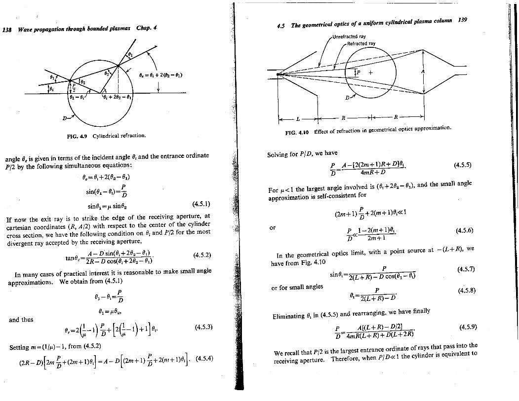
4.5 The' geometrical optics of a uniform cylidrical plasma column
A very approximate but useful model of common laboratory plasmasassumes a homogeneous cylindrical plasma several free-space wavelengths(of the probing microwave) in diameter, and yet neglects reflections at theboundary-the geometrical optics limit, The basic parameters of thisgeometry are defined in Fig, 4,8. The problem is assumed two-dimen-sional, the elements being of infinite extent normal to the paper, If theplasma is distant by at least a wavelength from the antenna, inductioneffects can be neglected and the situation treated as a radiation problem,If
Alb~1
Dlb~l,
geometrical optics is a valid approximation, and we can talk in terms ofrays which, except for refraction, travel in straight lines.
4.5.1 Transmission loss by refraction. We now consider the effect ofrefraction (Heald, i 959a; Wort, 1963). Since the index of refraction ofthe plasma (no magnetic field, or parallel polarization) is
¡. = (1- nlnc)'h .. 1
the plasma column constitutes a divergent cylindrical lens, With thehelp of Fig. 4,9 we compute the refraction of rays in the geometrical-optics limit for a homogeneous plasma with sharp boundaries, The exit
Transmittingantenna
Cylindricalplasma
Receivingantenna
~ 8 ~~--R I' R-l~FIG,4.8 Microwave beam geometry for a cylindrical plasma.
138' Wave propagation through bounded plasmas Chap. 4
FIG. 4.9 Cylindrical refraction.
angle 8e is given in terms of the incident angle 81 and the entrance ordinate
P 12 by the following simultaneous equations:
8e=8¡+2(82-81)
sin(81- 81)= PD
sin81 =¡. sin82 (4.5.1)
If now the exit ray is to strike the edge of the receiving aperture, at
cartesian coordinates (R, A12) with respect to the center of the cylinder
cross section, we have the following condition on 81 and PI2 for the mostdivergent ray accepted by the receiving aperture,
A - Dsin(81+282- 81)tan8"=2R_ D cos(81+282- 81f (4,5,2)
In many cases of practical interest it is reasonable to make small angleapproximations. We obtain from (4,5.1)
P81-81=-D81 = ¡.82,
and thus
8e=2(~- i) ~ + (2(~- i) + 1) 81, (4.5.3)
Setting m=(I/¡.)- I, from (4.5.2)
(2R-D)(2m ~ +(2m+ 1)81) =A- D((2m+ I) ~ + 2(ni + 1)81). (4,5.4)
),,¡-
4.5 The geometrical optics of a uniform cylindrical plasma column 139
i
I¡Unrefracted ray". Refracted ray
~ __ / L_----."' -----
L-lR ~FIG. 4.10 Effect of refraction in geometrical optics approximation.
Solving for PID, we have
P A-(2(2m+l)R+D)81D= 4mR+D .
For ¡.~1 the largest angle involved is (81+282-81), and the small angleapproximation is self-consistent for
(4.5.5)
or
P(2m + 1) D+2(m+l)81~d
P 1-2(m+ 1)81D~-( 2m+ 1 .
(4,5,6)
In the geometrical optics limit, with a point source at -(L+R), wehave from Fig. 4.10
sin81P
2(L+ R) - D cos(81 - 81)
P81 2(L+R)-D' (4.5,8)
(4.5,7)
or for small angles
Eliminating 8¡ in (4,5,5) and rearranging, we have finally
P _ A((L+R)- D12) .D- 4mR(L+R)+D(L+2R)
We recall that PI2 is the largest entrance ordinate of rays that pass into thereceiving aperture, Therefore, when pi D~-( 1 the cylinder is equivalent to
(4.5.9)

140 Wave propagation through bounded plasmas Chap. 4
a slab of thickness D. With the above evaluation of 81 the small angle
approximations wil be self-consistent if from (4,5.6)
P 2(L+R)-DD.c~2(2m+ l)(L+R)+ D
A 4mR(L + R) + D(L + 2R).c.c (2m + l)(L+ R) + Dj2 .
(4.5.10)
or using (4.5.9)
(4.5.11)
Neglecting dissipation in the plasma, we obtain a reduction in amplitudeat the receiving aperture because of the loss of highly refracted rays,This (power) transmission ratio is
T= P D(L+2R)P(¡.= I) 4mR(L+R)+ D(L+2R) (4,5.12)
15
'V-a.c'~
:8IIII.3
1.0
--- Refraction- Dissipation- - - - Reflection (max.)
10
--
I
I
,I
,,,IIIIII
II
III/,/,/,/,/../---
5
0,5Electron density (nIne)
FIG. 4.11 Loss of transmitted amplitude from refraction 4R(L + R)/ D(L + 2R) = 3.6,dissipation vD/wÀ=O.l, and reflection.
4.6 The antenll problem 141
ii
!I
Li
,I
~
where we recall that1m=--l¡.
l-_i",l n(l-nlnc)Yz "'2 ne + ' . ,
Figure 4.11 shows this transmission loss as a function of electron densityfor the particular case of
4R(L+R~ =3.6.
4.5.2 Other sources of loss. For comparison, we compute the dissipative
loss in the plasma due to collsions. From (1.3.30), for n": ne and lowdissipation (that is, v2.c.cwp2..w2), this transmission loss is given in decibelsby njne vD
T(dB) = -8.686 aD= -1T(8.686) 'l-nlneì'h 21TC' (4.5.13)
for rays passing near the center of the plasma. Figure 4,11 shows thisrelation for the numerical case
vD v D21TC =~ À =0.1.
For the numerical cases chosen, the refraction loss dominates except veryclose to the critical density.
Finally, we consider the question of interference effects due to reflections
at the sharp 'plasma-vacuum interfaces, In the usual case of PjD.cdthe only rays received are those which pass near the center of the plasma,and we can regard the plasma as a slab of thickness D, For the case of
lossless slabs, the transmission ratio (4,3.9) becomes
T 11 + C ~:2) 2 sin2e1T~D)
(4,5.14)
which varies between
( 2¡. )21 + ¡.2 .. T.. 1
as the relative phasing of the reflections changes, This maximumtransmission loss is also shown in Fig, 4,1 1 .
4.6 The antenna problem
The observed interaction of an electromagnetic wave with a plasma offinite size necessarily implies a "beamed" wave of finite extent and thusdepends upon the antenna system used to radiate and receive the wave(Beard et aL., i 962). The plane-wave model, which has been tacitly

142 Waiie propagation, through bounded plasmas Chap. 4
SourceS
I i
Ii
Iprnrn-ll
-I -
I
1-APerture¡
A Observati~, i plane I
IR ) IL ~ I (
I
(a)
I
-1--I-1--
iA
IlI
I(b)
~
Waveguide
ec....-~--
FIG, 4.12 Geometry of the physical optics of (a) an aperture, and (b) a microwavehorn antenna.
assumed in the preceding discussion, is a mathematical idealization whichoversimplifies the practical situation, especially when the wavelength isnot much smaller than the plasma sample, Therefore, it is useful toreview some of the basic principles of diffraction,
4.6.1 Fresnel zones. Consider a circular aperture, of diameter A, in anopaque screen iluminated with waves from a point S at a distance L tothe left, as in Fig, 4,I2a, We wish to investigate the nature of the radia-tion field in the vicinity of an observation point P on the axis a distance Rto the right. In accordance with elementary Huygens-Kirchhoff-Fresnel
diffraction theory, we may divide up the wave front in the aperture intoFresnel halfperiod zones, such that the radiation passing from S to Ptravels an additional half wavelength for each zone (Andrews, 1960),Specifically, the nth zone is a circular strip, the radius r n of the outer edgeof which is defined such that
,\(U+rn2)y. +(R2 +rn2)Y. =L+ R+n i' (4.6.1)
4.6 The antenna problem 143
Setting rn=Al2 and assuming Ac(c(L and R, (4,6,1) may be expandedbinomially to obtain
n= A2 (.!+.!).4,\ L R (4.6.2)
If the aperture is uniformly iluminated, the contributions of adjacentzones are out of phase and of approximately equal amplitude and,
thus, tend to canceL. Insight into the intensity distribution at variousobservation points (not necessarily on the axis) may be obtained byinvestigating the number of zones and the fractional area of each zoneexposed by the aperture, For instance (Fig, 4.13), the intensity at Pon the axis is a maximum for an aperture exposing i, 3, 5, . ,. zones,and a minimum for 2, 4, 6" . . zones. The intensity at a point off theaxis is small if roughly equal areas of odd and even numbered zones areexposed,
To a first approximation the radiation pattern of a horn antenna, ofdiameter A as in Fig, 4,12b, may be described by this analysis (Silver,1949), We are here interested in only a qualitative description and,therefore, wil not be concerned with the modifications req\lired by arectangular rather than circular aperture, by the polarization of an electro-magnetic (transverse) wave, and by nonuniformity of ilumination of thehorn aperture. However, in passing, it may be noted that for therectangular aperture with waveguide feed the diffraction field dependsupon two factors each of which depends, in turn, on only one of theaperture dimensions-that is, the two dimensions are uncoupled (Schel-
kunoffand Friis, 1952, Chapter 16), We take A to represent the dimension
controllng the radiation pattern of interest (for example, in the planeperpendicular to the axis of a cylindrical plasma as in Fig. 4,10), and
'I
:¡
:;,
(a) (b) (c)
FIG.4.13 Fresnel zones in a circular aperture; (0) on axis, (b) slightly off
axis, and
(c) far off axis (enlarged scale). (See also Fig. 9.26,)

1'4 Wave propagation through bounded plasmas Chal!..4,','.~,.';~.~
ignore the other dimension, Furthermore, we shall assume L~~ R so that
L drops out of the analysis and (4,6,2) becomes 6
n=A2/4ÀR. (4.6.3)
Typ.es of antennas other than horns may also be described in similarterms by suitably choosing an effective aperture dimension A,
If A, R, and À are such that the number n of exposed Fresnel zones is inthe range of one to ten, then strong interference fluctuations are to bea,Conversely, it may be noted that the criterion for "optimum" horn design-that is,
the choice of A to maximize the gain for a fixed length L-is effectively n ~ 1 forR~~L (Schelkunoff and Friis, 1952).
o
FIG. 4.14 H-plane intensity pattern in the field of a circular aperture, three wave-lengths in diameter. (Reproduced from Andrews, 1947, by courtesy of The PhysicalReview.)
'-ý;.:;.,,~:i,,:~:~:i
l~.
í
,':~
§~
'".cÕÍi:l!
1);...~
,.::
ii!i1.'
II
nr¡I
'"oJ1ic:
N Q)ãj'"'"~
o .E'"::o.g
N -. '"o "'~ eE
"f ßllEo
~ .:Q)oc:'"
co~. 0
4.6 The antenna problem 145
,-on .vi .~.. .,"'~5 ~- "".. c:
~~:2 S~ ~.5,§. iil! t:'" i:~ d0.ë~.. .... ..~ 0o ;.(. 00\l,- .... ..'- ::'0 0i: (... ;._ .0;. ..-: 00'" oni: 0\\l ..e_...:~i: i:~ ;00 ..
§ e(. 0
~~'- '0.. \lo (.00 ::.. '0:: 0o .... 0.i: l!o c:u '-
..II B.. l!~ e..d :.Ii ,5
\1
I
~'i¡:
,"
'"
Q
expected in the spatial vicinity of the point p, For low-order Fresnelinterference, amplitude variations are very large, the field pattern is"choppy" as indicated in Fig. 4. i 4, and phase anomalies occur (Andrews,1947, 1950; Linfoot and Wolf, 1956), A further example is shown inFig. 4,15 (Farnell, 1958),

146 Wave propagation through bounded plasmas Chap. 4
If n is very large, exclusion of induction fields requires R ~ À and
therefore A ~ 2nY. b). À, and the intensity distribution near P is essentially
that of geometrical optics; that is, uniform intensity fallng sharply to zeroin the geometrical shadow of the aperture. If a lens of focal
length R is
inserted at the aperture, a Fraunhofer diffraction pattern is obtained in theplane containing P, as in the familar problem of the astronomical
telescope,If, on the other hand, n is much less than unity, a Fraunhofer diffraction
pattern is obtained at P even without a lens. This is the familar far-fieldcase of conventional microwave antenna theory, To the extent that
n ~A2/4ÀRo(d,we have
R).). A2 /4À,
This is equivalent to the well-known rule for the far (Fraunhofer) field ofan antenna, which is usually written 7R~A2/À (4.6.4)and signifies that the maximum phase differential between "rays" is lessthan Àj8, or that the aperture is less than one-fourth of the first Fresnelhalf-period zone (Montgomery, 1947), The total angular width of thecentral maximum of the Fraunhofer diffraction pattern is 2À/A. There-fore, the spatial width of the central maximum fallng on a plane in thefar field is
(2À/A)R~2A.
Thus, if A).).À the intensity distribution in the vicinity of P is quite smoothover distances of the order of a wavelength, as in the high n case but in
contrast to the 1 ~ n ~ 10 case. The behavior of the field can be expectedto be qualitatively like the far field, up to a range corresponding to thefirst Fresnel half-period zone R=A2/4À (Hu, 1961),
4.6.2 Collimation. It is an interesting property of microwave optics thatone can satisfy the Fraunhofer diffraction criterion R~A2/À without theuse of collmating lenses as normally required in the optical region. Thatis, the "far field" of a radiation aperture, or an obstacle, is a much closerdistance, in wavelengths, than for similar apertures in the optical case.Therefore, in many situations, far-field theory can be used to describe themicrowave field, Meanwhile, the use of lenses becomes less powerfulsince the focal length F of the lens must beF~A2/À (4.6.5)7 Some antenna engineers use the criterion R?:2A2/)., corresponding to ),/16 orone-eighth zone. Amplitude errors due to interference are then about 2% asopposed to 5% for the criterion given above.
4.6 The antenna problem 147
if the focusing effect of the lens is to influence the diffraction pattern
appreciably. The so-called f number of the lens is then
f=F/A~A/À, (4.6.6)
When the geometrical optics condition A/b).l no longer holds, lensdesigns of smallfnumber are called for; these show strong aberration andare otherwise impracticaL. Stated differently, the width of the (Fraun-hofer) diffraction pattern at the focus of a lens is
(2ÀjA)F=2fÀ (4,6.7)with f~ 1 for practical lenses,
The far-field region can be effectively extended somewhat closer to theantenna aperture by using a lens to partially overcome the diffractionspreading (Sherman, 1962). The angular half-width of the centralmaximum of the Fraunhofer diffraction pattern is À/A. In geometricaloptics a ray leaving the edge of an aperture of width A at this angleappears to originate at a point located a distance A2/2À on the source sideof the aperture, and therefore the insertion of a lens of focal length
F=A2/2À wil render this extreme ray parallel to the axis, Thefnumberof such a lens is
f=A/U, (4,6,8)
agreeing closely with the upper limit of (4,6,6),Table 4,2 summarizes the characteristics of the radiation field' for
various regimes of the parameters, The best collmation ( .. À) is obtained
TABLE 4,2 FIELD PATTRNS AND COLLIMATION OF ANTENNAS
Number of zonesin aperture
! i. I
Small apertureA/Ìi~ 1
Large apertureA/b~ 1
n~~ 10
1..11;:10
n.. 1
Inductionfield region
Normal geometrical ray optics(collmation ~ A withoutlens; ~ À with lens)
Fresnel interference, "choppy"intensity distribution(collimation ~ A)
Fraunhofer diffraction radiation pattern (collmation2ÀRjA?: A)
in the A/ì\-I, n..l case (antenna far field) and the A/b;;l, n;;;;l0
case with lens (geometrical optics). The latter, however, is a strongly

148 Wave propagation through bounded plasmas Chap. 4
converging wave passing through a focus, It appears best to design
the experiment so as to avoid the low-order region (i ;Sn;S 10). If thenumber of Fresnel zones is either very large or small throughout thespace occupied by plasma and receiving antenna, then the iluminationwil be fairly uniform and the phase fronts well-behaved,
4.6.3 Optimization of antennas. Let us assume that we are given the
diameter D of a cylindrical plasma column and the wavelength ,\ withwhich we are to probe it, We further assume that '\, determined by theelectron density range to be measured and perhaps the availability ofshort-wavelength instrumentation, is small compared to D but by nomeans negligible. Since we wish to obtain a reasonable average of theelectron density independent of refraction (and diffraction) by the plasma,we wish to achieve maximum collmation of the microwave beam so thatit effectively passes along a diameter, We have seen from a geometricaloptics point of view that when ¡i": 1 the divergent lens action improves theeffective collmation by refracting nondiametric rays out of the receivingaperture, However, because of the danger of reflection from suchextraneous obstacles as the vacuum system walls, and because of the desireto conserve feeble milimeter-wave power, we wish to maximize the powerin received diametric rays and minimize it in nonreceived and/or non-diametric rays, That is, we wish to minimize the insertion loss between
antennas while ensuring that most of the radiation passes close to the axisof the plasma (Heald, 1959a).
The most clear-cut situation is when D~~A~~'\, which conforms closelyto infinite-slab, geometrical-optics conditions. However, our interest isin the case where perhaps I;S DI,\;S 10, If A:; D, appreciable energypasses around the plasma, reducing sensitivity and severely complicatinginterpretation, With D ~ A ~'\, in order to avoid induction field effectsand Fresnel-zone interference effects, we must have the plasma located inthe far (Fraunhofer) field of the antennas, R~A2/,\,
It is a well-known rule of antenna engineering that for a pair of antennasto be located in the far-field region, by the usual A2/,\ criterion, theminimum insertion loss is of the order of 16dB (Montgomery, 1947),Since only about two per cent of the radiated power is received, theprobability of interference from spurious reflected signals is high, Weare, therefore, interested in pushing as close to the near field (Fresnel zonenum ber n '" i) as possible without encountering severe amplitude and phasedisturbances from interference, This leads to the alternative of small(nondirective) antennas relatively close to the plasma or large (directive)antennas farther back.
4.6 The antenna problem 149
The concentration of rf energy produced in the field of a horn antennadepends upon two factors: the width of the wavepacket launched, and theangle of spread of the wave, Empirical plots of intensity contours in thefield of milimeter horn antennas indicate that one half of the energy isconfined within a beam width
W= ((a;) 2 + (b~R) 2) % (4,6,9)where a and b are correction factors depending on geometry and apertureilumination and departing only slightly from unity, For a given ,\ andR, this is minimized when
:1'
(2b )%A = -'\Ra
(4,6,10)
givinga A2R=--2b ,\
Wm1n=(ab'\R)%. (4,6.11)This condition corresponds to an aperture of about one half a Fresnel
half-period zone at R, The insertion loss between two such antennas
spaced 2R apart is about 8dB, depending upon the other dimension of the
antenna aperture, Sometimes mechanical constraints of the apparatuswil prescribe R, in which case A is determined by (4,6.10), If both Aand R are at the experimenter's disposal, it is necessary to consider therole of the diameter D of the plasma column, The relative beam sizeWI D varies as Rl' I D, whereas the relative spreading of the field over theplasma
D (8 W)W 8R Wmln
varies as DIR, Since we wish W~~D~~R, we arbitrarily takeD=(WminR)'I=(abì.R3)'/4, (4,6,12)
Recapitulating, given D and ì. and assuming a=b= i, we choose
(D)Y:R= - D
,\
A=(2ìR)'2=ÝI (~r D, (4,6.13)This heuristic argument is founded on the vague assumption that there issome virtue in minimizing the beam width at the plasma by choice of Aand then compromising in the choice of R such that
D RWmin - D'
The effect is to prescribe a situation in which the plasma is located slightly

150 Wave propagation through bounded plasmas Chap.-1
inside the conventional far-field boundary, We have seen, however, thatunder these conditions diffraction anomalies should not be very severe,Note that when Dlb~ 1, R-c-cD2lÀ and, therefore, the plasma approximatesan infinite slab as far as diffraction is concerned, By reciprocity andsymmetry arguments, we conclude that transmitting and receivingantennas should be identicaL.
The preceding discussion has been based on the assumption of simple
horn antennas without lenses, It has also assumed a "long" horn(L~A2lÀ) and L~2R, which may be impracticaL. Thus, two uses forlenses emerge: (1) to permit a less-than-long horn, in accord with con-ventional practice; and (2) to focus the beam or at least over~collmate tocompensate partially for diffraction, If a horn is "long," its far-field(R)-A2lÀ) pattern cannot be appreciably narrowed by addition of a lens.However, in the previous section we have discussed the use of a lens tofocus the energy at a distance R;SA2lÀ. The suggestion has been made touse converging lenses focused at the plasma axis (Boyd, 1959), This is
chiefly based upon the geometrical-optics argument that all rays passdiametrically through the plasma, thereby removing the refraction andsampling diffculties of the "plane-wave" approach, If Alb~ 1 so that agood focus can be obtained, and if this focus ( ~ À) is small relative to theplasma, Dlb~ I-that is, a good geometrical optics situation-thisprocedure has merits (Papoular and Wegrowe, 1961). However, in thiscase, the relative rf field strength becomes very high in the vicinity of thefocus, so that nonlinearities in the rf properties of the plasma may betroublesome, If, on the other hand, DlÀ~ 1, the so-called Gouy phase
anomalies in the vicinity of the focus (Fig, 4,15) could severely complicatethe interpretation (Linfoot and Wolf, 1956; Bekefi, 1957; and Farnell,1958), In this case, it appears that if lenses are to be used they should befocused at the opposite antenna or beyond (Christian and 'Goubau, 1961).Further discussion of the practice of using lenses can be found in Sections6.4 and 9,3.
Because of the perturbation that thick dielectric windows (glass, mica,quartz, etc,) make on the field of a milimeter-wave antenna (Redheffer,1949), it is often useful to locate the vacuum seal at a convenient pointback in the waveguide so that the antennas are wholly within the vacuumsystem, Such window design follows standard practice as used inmicrowave tube output windows and waveguide pressurizing windows;examples are given in Section 9,6. Alternatively, care must be taken to
provide matching structures at the vacuum walls (Jahn, 1962),
4.6.4 Validity of the geometrical-optics, slab model. Since the geo-metrical-optics, plane-slab model
is particularly convenient to analyze,
'.~.ç\~;
4.6 The antenna problem 151
-270
20ãí~c:
10,g'":ic:
£lo ci
'i -180Q)~QOQ)E-so(;l:EVIQ)VI'".cc.
+90
o 2 3Diameter D/-l (in paraffin)
FIG, 4,16 Phase shift and attenuation as a function of cylinder diameter in paraffnanalog experiment (Rosen, 1949), Wave E-field parallel to cylinder axis. Dimensionsnormalized to wavelength in the medium of the antennas: H-plane aperture of horn3.1; E-planeaperture 2.6; axial length of horn (to apex) 6.8; horn separation 13.4.Measurement frequency 35 Gc,
it is of interest to investigate the validity of this model for the morepractical case of a cylindrical plasma, In addition, since the nearness ofthe antennas, as well as of extraneous objects such as vacuum system walls,severely complicates theoretical analysis, it is often most effective to
perform an analog experiment (Warder, Brodwin, and Cambel, 1962;
lams, 1950; and Lashinsky, 1963),
A plasma, with dielectric constant less than unity, can be simulated bycutting holes in a large block of low-loss dielectric, in which a scaled
antenna system is imbedded. In one such experiment the phase shift andinsertion loss were measured for various size cylindrical holes cut in
w~ -- ,./ ", /..' "" - . ; -b~è. I'
~-LR ,I' R--FIG, 4,17 Propagation through a dielectric cylinder, small compared to effectivemicrowave beam.
152 Wave propagation through bounded plasmas Chap."
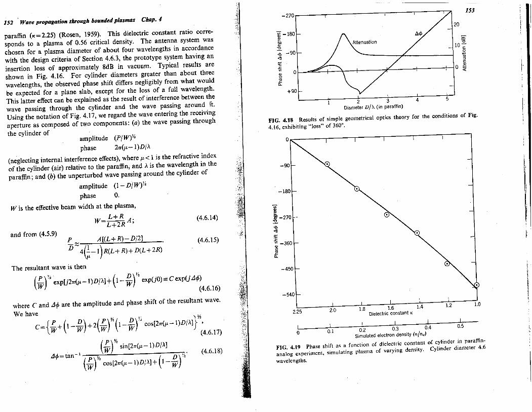
paraffn (K=2,25) (Rosen, 1959), This dielectric constant ratio corre-sponds to a plasma of 0,56 critical density, The antenna system waschosen for a plasma diameter of about four wavelengths in accordance
with the design criteria of Section 4,6,3, the prototype system having aninsertion loss of approximately 8dB in vacuum, Typical results areshown in Fig, 4,16, For cylinder diameters greater than about threewavelengths, the observed phase shift differs negligibly from what wouldbe expected for a plane slab, except for the loss of a full wavelength,
This latter effect can be explained as the result of interference between thewave passing through the cylinder and the wave passing around 1t,Using the notation of Fig, 4,17, we regard the wave entering the receivingaperture as composed of two components: (0) the wave passing throughthe cylinder of
amplitude (PlW)Yi
phase 27T(¡-1)DlA
(neglecting internal interference effects), where fL' 1 is the refractive indexof the cylinder (air) relative to the paraffn, and A is the wavelength in theparaffn; and (b) the unperturbed wave passing around the cylinder of
amplitude (1 - DlW)%phase O.
W is the effective beam width at the plasma,L+R
W=L+2RA;
and from (4,5,9)P A((L+R)-Dl2)D'; 4(~-1)R(L+R)+D(L+2R)'
The resultant wave is then
(4,6,14)
(4,6,15)
(P)" ( D"W ,2 eXPU27T(¡-1)DlA)+ 1- W r exp(jO)= C exp(j LJif)(4.6.16)
where C and LJif are the amplitude and phase shift of the resultant wave,We have
f P ( D) (P)~~( D)% ì.YzC=ì.W+ 1- W +2 W 1- w cos(27T(fL-1)DlA)J'(4,6,17)
( P)Yi-1 W sin(27T(fL-l)DlA)LJif=tan P Yi D ~2'(w) cos(27T(fL-l)DlA) + (1 - w)
(4,6,18)
2 3Diameter vjÀ (in paraffn)
FIG, 4.18 Results of simple geometrical optics theory for the conditions of Fig.4.16, exhibiting "loss" of 360°.
-270
~ -180Q)boQ)'0
-e - 90~--.rV1Q) 0V1'".ra.
+90
-90
ViQ)Q)
~ -270~-e~~~ -360Q)V1'".ra.
-450
-540
153
20 I
\
ãi'0
10 -;
.g'"OJi:Q)
o ~
4 5
2.25 ¿u i,u 1.6Dielectric constant"i I I I i I_ , 0,2 0,3 0.4 0,5Simulated electron density (nIne)
FIG, 4.19 Phase shift as a function of dielectric constant of cylinder in paraffn-analog experiment, simulating plasma of varying density. Cylinder diameter 4.6
wavelengths.
154 Wave propagation through bounded plasmas Clup.-I
The theoretical C and ¿tn, are plotted in Fig. 4.18 for parameters corre-sponding to the experimental conditions of Fig, 4,16, In order to obtain
these relations for C and ¿tn" several small-angle approximations have beenmade, diffraction was completely neglected, and interference effectsinside the cylinder were disregarded, In spite of the crudity of the
geometrical optics analysis, the numerical agreement is reasonably good,This "lost-wavelength" effect could cause misleading results in a plasma
experiment in the uncommon situation in which the plasma is createdwith a small diameter ( .. 2'\) which subsequently grows larger.8 Morecommonly, the plasma is created with a relatively large diameter ()o 3'\)and then grows denser (due to increased ionization) or smaller (due tosome form of magnetic compression). In these cases, the transition fromthe vacuum (no plasma) phase-shift condition, as the plasma develops,appears to be unambiguous, By inserting rods of various knowndielectric constants in a fixed diameter hole in the paraffn environment,the data of Fig. 4,19 was obtained, simulating varying plasma densities
(Rosen, 1959), On the basis of this study, we conclude that the,slabanalysis is satisfactory for a cylindrical plasma diameter of at leas( threewavelengths, provided the antenna system is chosen judiciously,8 The expanding-diameter situation could occur during a plasma decompressionevent or an expanding cylindrical shock.
...:......¡"".1.
. ~'.
,;' 'l
r
CHAPTER 5
Guided wave propagation
5.0 Introduction
The effects of finite plasma dimensions on wave propagation werediscussed in Chapter 4, The boundaries were found to cause reflectionsand refraction of transmitted waves and, in some cases, to affect theradiation patterns of antennas, In most cases, the boundaries led toproblems, rather than being beneficial to the propagation experiments:
In the present chapter, we discuss another class of bounded plasmas; in
this case, boundaries are essential to the wave propagation, Resonantcavities and waveguides have metallic walls that carry currents and, thus,set up propagation modes, The electromagnetic fields penetrate theenclosed plasma, whose conductivity, in turn, affects the mode cut-offfrequency. Measurements of wave phase shift or resonant frequency andloaded Q then can be related to the plasma properties.
Plasmas having vacuum or dielectric boundaries can support space-charge-wave modes and, thus, can act as waveguides, Certain space-charge-wave modes propagate along the plasma surface (surface waves),while others are carried within the plasma (body waves), When amagnetic field is present, the waves tend to be a combination of both types,
Electromagnetic waves and spacecharge waves may propagate simul-taneously along the same bounded plasma. Under certain conditions, thedifferent wave types may couple to one another but, in general, thecoupling coeffcients are rather smalL.
5.1 Measurements on plasmas contained in resonant cavitiesThe resonance properties of a cavity containing a lossy dielectric can bestated in terms of Q
155