l 4 assembly language and computer architecture...language (with the aid of an architecture manual)....
TRANSCRIPT

© 2008–2018 by the MIT 6.172 Lecturers 1
6.172 Performance Engineering of Software Systems
!"##$ %&'&(
"#)*+)$#)*+,*-./01 !
LECTURE 4 Assembly Language and Computer Architecture Charles E. Leiserson

Source Code to Execution
Source code fib.c Machine code fib
© 2008–2018 by the MIT 6.172 Lecturers 2
Execution PreprocessingCompiling Assembling Linking
Hardware interpretation
four stages
! "#$%&'()*+" ,-'()* ! +.()*
Compilation
)%/012/ ()*3)%/012/ %4 5 )( 3% 6 74 89/:8% %; 89/:8% 3()*3%<=4 > ()*3%<744;
?
@=@=@=@='@=@@=@@@'=@@@=@@= ===@@=@='@=@=@@=='@=@@=@@@ =@@@@@=='===@==@@'@@@@=@@@ =@@@=@@='@=====@='====@=@@ =@@@@@=='@=====@='====@=@@ @@@@@@@='@======='@@@@=@@@ =@@@=@=='@=@@@=@='====@=@@ =@@@=@@='@=@@@=@='====@@@@ ===@=@=='@@@===@='=@@@=@== @=@@@=@='====@=@@'=@@@==@= @====@@@'========'===@=@@@ ==@==@=='========'======== ========'=@@@=@@='==@@@@== =@@@=@=='@=@@@=@='====@=@@ =@@@==@='@====@@@'=======@ ===@=@@@'==@@===@'======== ========'========'@@@@@@@= ==@@@@=='=@@@=@@='@=@===@= ====@@@@'=@@@=@=='@=@@@=@= ====@@@@'@=@@=@@@'=@@@@@== ==@@@=@@'@@@@=@@@'@=@==@== ==@@=@@='==@@@@==

The Four Stages of Compilation
© 2008–2018 by the MIT 6.172 Lecturers 3
Binary executable
Assembly
Preprocessed source
Source
! "#$%&'()
! "#$%&'(*
! "#$%&'("
! #+
Preprocess
Compile
Assemble
Link
Preprocess
Compile
Assemble
Object file
Manual invocation ,-.$//$01"
,-.$//$01-
,-.$//$012
,-.$//$013
4$-%1"
4$-%1-
4$-%12
4$-%13
565/0,-.
#-,/$/-52

Source Code to Assembly Code
Assembly code !"#$%
Assembly language provides a convenient symbolic representation of machine code.
See http://sourceware.org/binutils/docs/as/index.html.
Source code !"#$&
' &()*+,-./,!"#$& -0
"*12341 !"#5"*12341 *6 7"! 5* 8 96 :;1<:* *= :;1<:* 5!"#5*>?6 @ !"#5*>966=
A
$+(B#( 4!"# $C9)("+* 3D EFGE
4!"#H II,J!"# C<%KL M:#C NBOL M:%CD M:#C C<%KL M:?3 C<%KL M:#F NBOL M:P"D M:#F &NCL '9D M:#F Q+; RSSE4? NBOL M:#FD M:)F QNC RSSE4/
RSSE4?H (;)L >?5M:#F6D M:P" &)((L 4!"# NBOL M:)FD M:?3 )PPL '>9D M:#F NBOL M:#FD M:P" &)((L 4!"# )PPL M:?3D M:)F
RSSE4/H CBCL M:#F CBCL M:?3 CBCL M:#C :;1L
© 2008–2018 by the MIT 6.172 Lecturers 4

Assembly Code to Executable
Assembly code !"#$% Machine code
You can edit !"#$% and assemble with &'()*.
+ &'()*,!"#$% -.,!"#$.
Assembling
$01('"*) 23 4564 /!"#7 88,9!"#
0:%;< =>#0 ?.@< =>%03 =>#0 0:%;< =>A2 0:%;< =>#5 ?.@< =>B"3 =>#5 &?0< +13 =>#5C*D EFF4/A?.@< =>#53 =>(5C?0 EFF4/G
EFF4/A7 'D(< HAI=>#5J3 =>B" &(''< /!"# ?.@< =>(53 =>A2 (BB< +H13 =>#5?.@< =>#53 =>B"&(''< /!"#(BB< =>A23 =>(5
EFF4/G7 0.0< =>#5 0.0< =>A2 0.0< =>#0 >DK<
&'()*
4A4A4A4A,4A44A444, A444A44A,AAA44A4A, 4A4A44AA,4A44A444 A44444AA,AAA4AA44, 4444A444,A444A44A, 4AAAAA4A,AAAA4A44 A44444AA,4AAAAA4A, AAAA4A44,4444444A, 4AAAAAAA,4444A444 A444A4AA,4A444A4A, AAAA4A44,A444A44A, 4A444A4A,AAAA4444 AAA4A4AA,444AAA4A, A444A4AA,4A444A4A, AAAA4A44,A444AA4A 4AAAA444,AAAAAAAA, AAA4A444,AA4AA4AA, AAAAAAAA,AAAAAAAA AAAAAAAA,A444A44A, AA4444AA,A444A4AA, 4A444A4A,AAAA4A44 L
© 2008–2018 by the MIT 6.172 Lecturers 5
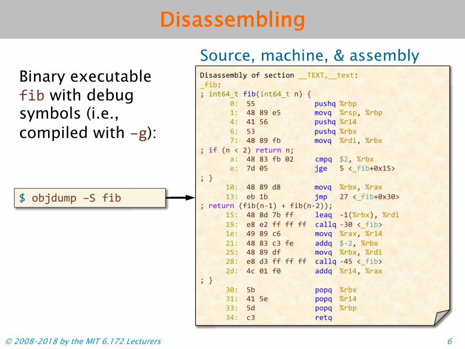
Disassembling
Source, machine, & assembly
© 2008–2018 by the MIT 6.172 Lecturers 6
Binary executable !"# with debugsymbols (i.e., compiled with $%):
& '#()*+, $-.!"#
/"01002+#34.'!.0256"'7.889:;9<8862=6> 8!"#> ? "76@A86 !"#B"76@A86 7C D
E> FF. ,*0GH IJ#, K> AL.LM.2F. +'NH IJ0,< IJ#, A> AK.F@. ,*0GH IJKA @> FO. ,*0GH IJ#= P> AL.LM.!# +'NH IJ)"< IJ#=
? "! B7 Q RC J26*J7 7? 1> AL.LO.!#.ER. 5+,H &R< IJ#= 2> P).EF. (%2 F Q8!"#SE=KFT
? U KE> AL.LM.)L. +'NH IJ#=< IJ1= KO> 2# K#. (+, RP Q8!"#SE=OET
? J26*J7 B!"#B7VKC S !"#B7VRCC? KF> AL.L).P#.!! 321H VKBIJ#=C< IJ)" KM> 2L.2R.!! !! !! 5133H VOE Q8!"#T K2> AM.LM.5@ +'NH IJ1=< IJKA RK> AL.LO.5O.!2 1))H &VR< IJ#= RF> AL.LM.)! +'NH IJ#=< IJ)" RL> 2L.)O.!! !! !! 5133H VAF Q8!"#T R)> A5.EK.!E 1))H IJKA< IJ1=
? U OE> F# ,',H IJ#= OK> AK.F2 ,',H IJKA OO> F). ,',H IJ#, OA> 5O. J26H

Why Assembly?
Why bother looking at the assembly of your program? ∙ The assembly reveals what the compiler did and did
not do.∙ Bugs can arise at a low level. For example, a bug in
the code might only have an effect when compilingat –O3. Furthermore, sometimes the compiler is thesource of the bug!
∙ You can modify the assembly by hand, when all elsefails.
∙ Reverse engineering: You can decipher what aprogram does when you only have access to itsbinary.
© 2008–2018 by the MIT 6.172 Lecturers 7
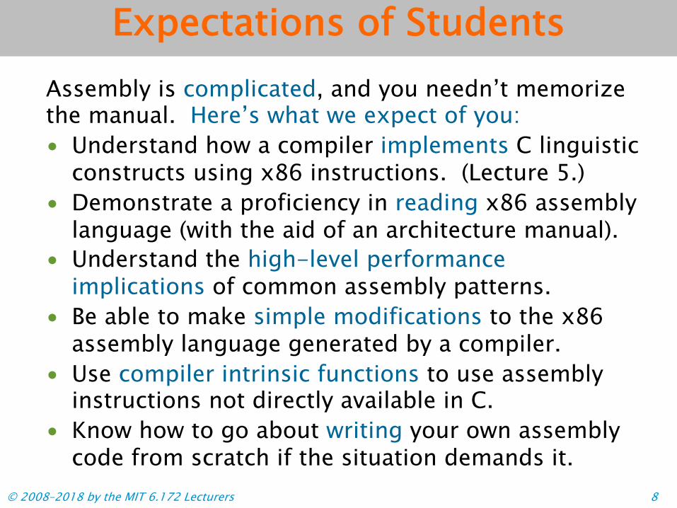
Expectations of Students Assembly is complicated, and you needn’t memorize the manual. Here’s what we expect of you: • Understand how a compiler implements C linguistic
constructs using x86 instructions. (Lecture 5.)• Demonstrate a proficiency in reading x86 assembly
language (with the aid of an architecture manual).• Understand the high-level performance
implications of common assembly patterns.• Be able to make simple modifications to the x86
assembly language generated by a compiler.• Use compiler intrinsic functions to use assembly
instructions not directly available in C.• Know how to go about writing your own assembly
code from scratch if the situation demands it.© 2008–2018 by the MIT 6.172 Lecturers 8

Outline
• X86-64 ISA PRIMER• FLOATING-POINT AND VECTOR HARDWARE• OVERVIEW OF COMPUTER ARCHITECTURE
© 2008–2018 by the MIT 6.172 Lecturers 9

!"##$ %&'&(
"#)*+)$#)*+,*-./01 !
© 2008–2018 by the MIT 6.172 Lecturers 10
X86-64 ISA PRIMER

The Instruction Set Architecture
The instruction set Example architecture (ISA) specifies the syntax and semantics of assembly. ! Registers! Instructions! Data types! Memory addressing
modes
!"#$ %&'() %&*+ ,!-$ ./) %&*+ 012 344567 !"#$ %&*+) %&8+ 0!- 344569
344567: ;28$ <7=%&*+>) %&'( ,8;;$ 6?(* !"#$ %&8+) %&7@ 8''$ .</) %&*+ !"#$ %&*+) %&'( ,8;;$ 6?(* 8''$ %&7@) %&8+
Instruction
Register
Indirect memory address
,!-$ ./)) %&*+
<7=<7=%&*+>);28$
Immediate value
344567344567%&*+%&*+)!"#$
0!-
.</.</8''$
© 2008–2018 by the MIT 6.172 Lecturers 11

x86-64 Registers
© 2008–2018 by the MIT 6.172 Lecturers 12 © 2008–2018 by the MIT 6.172 Lecturers 12© 2008 2018 by the MIT 6.172 Lecturers 12
Number Width (bits)
Name(s) Purpose
16 64 (many) General-purpose registers 6 16 !""#!$%&'(" Segment registers 1 64 RFLAGS Flags register 1 64 !)*+ Instruction pointer register 7 64 !%)$,&-#.(#/!0%), Control registers 8 64 !11$,&2( MMX registers 1 32 mxcsr SSE2 control register
16 128 !011$,&34( XMM registers (for SSE) 256 !511$,&34( YMM registers (for AVX)
8 80 !"67$,&2(8 x87 FPU data registers 1 16 x87 CW x87 FPU control register 1 16 x87 SW x87 FPU status register 1 48 x87 FPU instruction pointer register 1 48 x87 FPU data operand pointer
register 1 16 x87 FPU tag register 1 11 x87 FPU opcode register

Common x86-64 Registers
© 2008–2018 by the MIT 6.172 Lecturers 13 © 2008–2018 by the MIT 6.172 Lecturers 13© 2008 2018 by the MIT 6.172 Lecturers 13
Number Width (bits)
Name(s) Purpose
16 64 (many) General-purpose registers 6 16 !""#!$%&'(" Segment registers 1 64 RFLAGS Flags register 1 64 !)*+ Instruction pointer register 7 64 !%)$,&-#.(#/!0%), Control registers 8 64 !11$,&2( MMX registers 1 32 mxcsr SSE2 control register
16 128 !011$,&34( XMM registers (for SSE) 256 !511$,&34( YMM registers (for AVX)
8 80 !"67$,&2(8 x87 FPU data registers 1 16 x87 CW x87 FPU control register 1 16 x87 SW x87 FPU status register 1 48 x87 FPU instruction pointer register 1 48 x87 FPU data operand pointer
register 1 16 x87 FPU tag register 1 11 x87 FPU opcode register

x86-64 Register Aliasing
The x86-64 general-purpose registers are aliased: each has multiple names, which refer to overlapping bytes in the register. General-purpose register layout
!"#$%&'(#$)'*+$,%+"$*#-'+%./0"%)$12$*134$,'0$/.+$5.6/3$%/$ +"#$5%-#7
!"#$
!%#$
!#$
!#& !#'
Byte 7 Byte 6 Byte 5 Byte 4 Byte 3 Byte 2 Byte 1 Byte 0
Only !"#$, !"($, !")$, and !"*$ have a separate
register name for this byte.
© 2008–2018 by the MIT 6.172 Lecturers 14

x86-64 General-Purpose Registers
© 2008–2018 by the MIT 6.172 Lecturers 15
64-bit name 32-bit name 16-bit name 8-bit name(s)
!"*$ !%*$ !*$ !*&' !*) !"+$ !",$ !%,$ !,$ !,&' !,) !"-. !",. !%,. !,. !,.) !"*/ !"-/ !%-/ !-/ !-/) !"0 !"2 !"2, !"21 !"2* !"34 !"33 !"33, !"331 !"33* !"35 !"36 !"36, !"361 !"36* !"37 !"38 !"38, !"381 !"38*
!"37, !"371 !"37*
!"35, !"351 !"35*
!"34, !"341 !"34*
!"0, !"01 !"0*
!%*/ !*/ !*/)
!%-. !-. !-.)
!%+$ !+$ !+&' !+)
!"#$ !%#$ !#$ !#&'(!#)

x86-64 Instruction Format
Format: !opcode" !operand_list" ! !opcode" is a short mnemonic identifying
the type of instruction. ! !operand_list" is 0, 1, 2, or (rarely) 3
operands, separated by commas. ! Typically, all operands are sources, and
one operand might also be the destination.
!""# $%"&'($%)* Example:
Opcode
!""#
Operand list Destination operand
%"&'($%)*© 2008–2018 by the MIT 6.172 Lecturers 16

2018 by the MIT 6.172 Lecturers
AT&T versus Intel Syntax
What does “<op> A, B” mean?
AT&T Syntax B ! B <op> A
Intel Syntax A ! A <op> B
!"#$ %&'()*+, !"# *+,'(&
+--$ .)*/,')*0,'1,23'()*+, +--(*+,'(4*/,5*0,6278
9:/; 1,21.)</,3' )<+, 9:/(<+,'(4</,52178
Generated or used by 0$+=>, "/?-:!@, @*<A,
6.172 lectures.
Used by Intel documentation.
© 2008–2018 by the MIT 6.172 Lecturers 17

Common x86-64 Opcodes Type of operation Examples
Data movement Move !"# Conditional move $!"#
Sign or zero extension !"#%, !"#&Stack '(%), '"'
Arithmetic and logic
Integer arithmetic *++, %(,, !(-, .!(-, +.#, .+.#, -/*, %*-, %*0, %)-, %)0, 0"-,
0"0, .1$, +/$, 1/2Binary logic *1+, "0, 3"0, 1"4
Control transfer Unconditional jump 5!'
Subroutines $*--, 0/4
Boolean logic 4/%4, $!'
Conditional jumps 5<condition>
Note: The subtraction operation “%(,6 70*38970,3” computes 70,3 = 70,3 - 70*3.
© 2008–2018 by the MIT 6.172 Lecturers 18

Opcode Suffixes Opcodes might be augmented with a suffix that describes the data type of the operation or a condition code. ! An opcode for data movement, arithmetic, or
logic uses a single-character suffix toindicate the data type.
! If the suffix is!"#$ %&'()*+,-./)*01
Moving a 64-bit integer.
!"#$
Example missing, it canusually be inferredfrom the sizes of theoperand registers.
© 2008–2018 by the MIT 6.172 Lecturers 19

x86-64 Data Types
C declaration C constant
x86-64 size
(bytes)
Assembly suffix
x86-64 data type
char 'c' 1 b Byte
short 172 2 w Word
int 172 4 l or d Double word
unsigned int 172U 4 l or d Double word
long 172L 8 q Quad word
unsigned long 172UL 8 q Quad word
char * "6.172" 8 q Quad word
float 6.172F 4 s Single precision
double 6.172 8 Double precision
long double 6.172L 16(10) t Extended precision
d
© 2008–2018 by the MIT 6.172 Lecturers 20

Opcode Suffixes for Extension Sign-extension or zero-extension opcodes use two data-type suffixes. Examples:
!"#$%& '(&)*'+,-
Move an 8-bit integer into a 32-bit integer
register.
!"#$%&
Extend with zeros.
!"#$%& !"#.&/ '+(-, '0,-
Move a 32-bit integer into a 64-bit integer
register.
!"#.&/
Preserve the sign.
!"#.&/
Careful! Results of 32-bit operations are implicitly zero-extended to 64-bit values, unlike the results of 8- and 16-bit operations.
© 2008–2018 by the MIT 6.172 Lecturers 21

Conditional Operations
Conditional jumps and conditional moves use a one- or two-character suffix to indicate the condition code.
!"#$ %&'()*+,-.& /01 2344.5.
The jump should only be taken if the arguments of the previous
comparison are not equal.
01
Example
© 2008–2018 by the MIT 6.172 Lecturers 22

RFLAGS Register
© 2008–2018 by the MIT 6.172 Lecturers
Bit(s) Abbreviation Description 0 CF Carry 1 Reserved 2 PF Parity 3 Reserved 4 AF Adjust 5 Reserved 6 ZF Zero 7 SF Sign 8 TF Trap 9 IF Interrupt enable 10 DF Direction
Overflow System flags or reserved
OF 12-6311
Arithmetic and logic operations update status flags in the RFLAGS register.
23
!"#$ %&'( )*" +,--./0
Example:
Decrement %&'(, and set ZF if the result is 0.
!"#$ %&'(%&'(
2323
Jump to label +,--./0if ZF is not set.
)*" +,--./0+,--./0

RFLAGS Register
© 2008–2018 by the MIT 6.172 Lecturers 24
Bit(s) Abbreviation Description 0 CF Carry 1 Reserved 2 PF Parity 3 Reserved 4 AF Adjust 5 Reserved 6 ZF Zero
8 TF Trap 9 IF Interrupt enable 10 DF Direction 11 OF Overflow 12-63 System flags or
reserved
The last ALU operationgenerated a carry or borrow out of the most-significant bit.
The result of the last ALU operation was 0.
The last ALU operationproduced a value whose sign bit was set.
The last ALU operationresulted in arithmetic overflow.
Sign SF 7

Condition Codes
© 2008–2018 by the MIT 6.172 Lecturers 25
TranslationCondition code RFLAGS status flags checked
a if above CF = 0 and ZF = 0 ae if above or equal CF = 0 c on carry CF = 1 e if equal ZF = 1 ge if greater or equal SF = OF ne if not equal ZF = 0 o on overflow OF = 1 z if zero ZF = 1
© 2008 2018 by the MIT 6.172 Lecturers
Question: Why do the condition codes ! and "! check the
zero flag?
Answer: Hardware typically compares
integer operands using subtraction.

ExamplesExamples
x86-64 Direct Addressing Modes
The operands of an instruction specify values using a variety of addressing modes. ! At most one operand may specify a memory
address.
Direct addressing modes Examples ! Immediate: Use the
specified value.! Register: Use the value in
the specified register.! Direct memory: Use the
value at the specifiedmemory address.
!"#$ %&'()*+,-.
!"#$ +,/0)*+,-.
!"#$ 10&'()*+,-.
© 2008–2018 by the MIT 6.172 Lecturers 26

x86-64 Indirect Addressing Modes The x86-64 ISA also supports indirect addressing: specifying a memory address bysome computation. ! Register indirect: The Examples Examples
%&'( )!"*+,-.!"/#
%&'( 012)!"*+,-.!"/#
address is stored in thespecified register.
! Register indexed: Theaddress is a constantoffset of the value in thespecified register.
! Instruction-pointerrelative: The address isindexed relative to !"#$.
%&'( 012)!"#$,-.!"/#
© 2008–2018 by the MIT 6.172 Lecturers 27

Base Indexed Scale Displacement
The most general form of indirect addressing supported by x86-64 is the base indexed scale displacement mode.
!"#$ %&'()*+,-.)*+/-.01-.)*2/Example
Base: a GPR
%&'()*+,
Index: a GPR
-.)*+/*+/-.01-.)
Displacement: an 8-bit, 16-bit, or 32-bit value.
%&'()
Scale: either 1, 2, 4, or 8.
-.01-.)
This mode refers to the address Base + Index*Scale + Displacement. If unspecified, Index and Displacement default to 0, and Scale defaults to 1.
© 2008–2018 by the MIT 6.172 Lecturers 28

Jump Instructions
The x86-64 jump instructions, !=> and !!condition", take a label as their operand, which identifies a location in the code.
! Labels can besymbols, exactaddresses, orrelative addresses.
! An indirect jumpExample from A)!:B=> '() takes as its operand
!"# ;<<+&-/
;<<+&-0 1#23 4-567),89 67:(
Example from '()?@
/;<<+&-0
© 2008–2018 by the MIT 6.172 Lecturers 29 © 2008 2018 by the MIT 6.172 Lecturers
!"# $ %&'()*+,-$. /
-$0 1#23 4-567),89 67:(
an indirect address. /
-$0 Example: !=> C6#2,

Assembly Idiom 1
The XOR opcode, “!"# $% &,” computes the bitwise XOR of $ and &.
Question: What does the following assembly do?
!"# '#(!%)'#(!
Answer: Zeros the register.
© 2008–2018 by the MIT 6.172 Lecturers 30
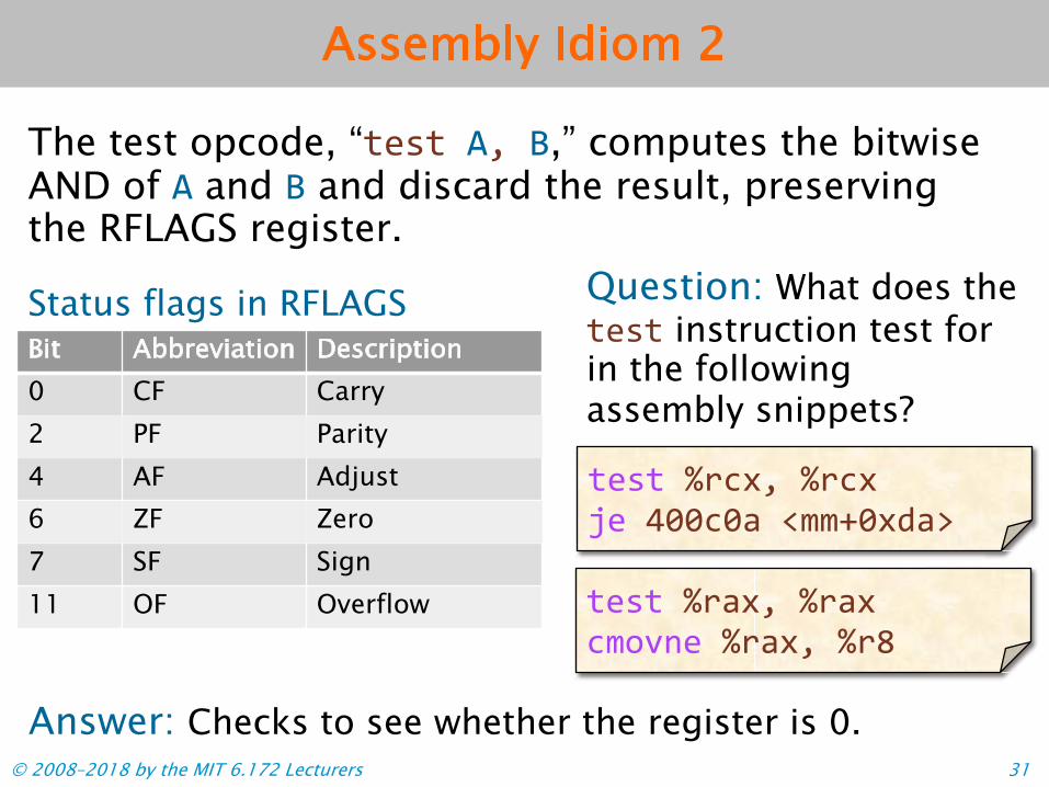
Assembly Idiom 2
The test opcode, “!"#! 7( 8,” computes the bitwise AND of 7 and 8 and discard the result, preserving the RFLAGS register.
Question: What does the Status flags in RFLAGS Bit Abbreviation Description
!"#! instruction test for 0 CF Carry 2 PF Parity 4 AF Adjust 6 ZF Zero 7 SF Sign 11 OF Overflow
!"#! $%&'()$%&' *" +,,&,-).//0,'1-2
!"#! $%-'()$%-' &/345" $%-'()$%6
in the followingassembly snippets?
Answer: Checks to see whether the register is 0. © 2008–2018 by the MIT 6.172 Lecturers 31

Assembly Idiom 3
The x86-64 ISA includes several no-op (nooperation) instructions, including “!"#,” “!"# $,” (no-op with an argument), and “%&'&().”
Question: What does this line of assembly do?
%&'&() %&'&() %&'&() !"#* +,-./0/1+2&03+2&03(4
Answer: Nothing!
Answer: Mainly, to optimize instruction memory (e.g., code
size, alignment).
Question: Why would the compiler generate assembly with these
idioms?
© 2008–2018 by the MIT 6.172 Lecturers 32
!"##$ %&'&(
"#)*+)$#)*+,*-./01 !
© 2008–2018 by the MIT 6.172 Lecturers 33
FLOATING-POINT AND VECTOR HARDWARE

Floating-Point Instruction Sets
Modern x86-64 architectures support scalar (i.e., non-vector) floating-point arithmetic via a couple of different instruction sets. • The SSE and AVX instructions support single-
precision and double-precision scalar floating-pointarithmetic, i.e., “float” and “double.”
• The x87 instructions support single-, double-, andextended-precision scalar floating-point arithmetic,i.e., “float,” “double,” and “long double.”
The SSE and AVX instruction sets also include vector instructions.
© 2008–2018 by the MIT 6.172 Lecturers 34

!"#$% !"#$% '()*
+'($,
&'()*!12$%
'(4*'(4*4%%$%
SSE for Scalar Floating-Point
Compilers prefer to use the SSE instructions over the x87 instructions because SSE instructions are simpler to compile for and to optimize. ! SSE opcodes on
floating-point values are similar to x86_64
Example
opcodes. '*!!3'*!!3!12$% '*!!3! SSE operands use
XMM registers andfloating-point types.
& +'($,+-.+/'*!!0 +/'*!!0
& +-.+/'*!!0 !"#$% '*!!0+/&'(4*+'($,+-.
Data type is a double-precision floating-point
value (i.e., a %"1526).
+'($,+/&++/&+/&
4%%$% &'(4*'(4*'*!!0+/&!"#$% '*!!0'*!!0
© 2008–2018 by the MIT 6.172 Lecturers 35

2018 by the MIT 6.172 Lecturers
SSE Opcode Suffixes
SSE instructions use two-letter suffixes to encode the data type.
Assembly suffix Data type
ss One single-precision floating-point value (!"#$%) sd One double-precision floating-point value (&#'(")) ps Vector of single-precision floating-point values pd Vector of double-precision floating-point values
Mnemonic ! The first letter distinguishes
single or packed (i.e., vector).! The second letter distinguishes
single-precision or double-precision.© 2008–2018 by the MIT 6.172 Lecturers 36

Vector Hardware Modern microprocessors often incorporate vector hardware to process data in a single-instruction stream, multiple-data stream (SIMD) fashion.
Lane 0 Lane 1 Lane 2 Lane 3
Word 0 Word 1 Word 2 Word 3
Vector Load/Store Unit
ALU
Vector Registers
Memory and caches
ALU ALU ALU
Inst
ruct
ion
deco
dean
d se
quen
cing
© 2008–2018 by the MIT 6.172 Lecturers 37
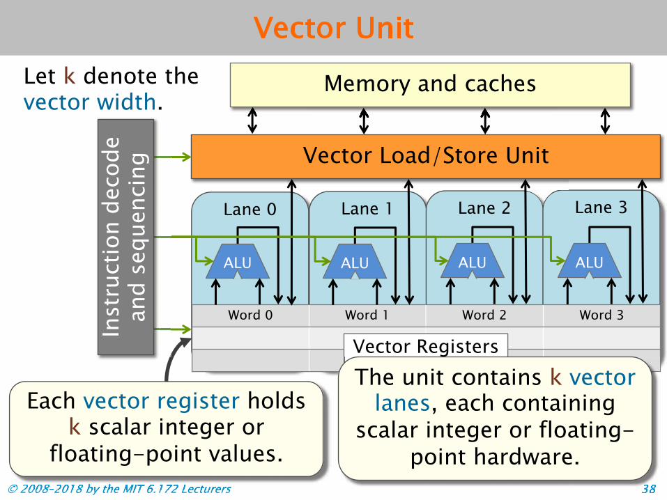
Vector Unit
© 2008–2018 by the MIT 6.172 Lecturers 38 © 2008© 2008–2018 by the MIT 6.172 Lecturers© 2008 2018 by the MIT 6.172 Lecturers
Each vector register holds k scalar integer or
floating-point values.
Let k denote the vector width.
Lane 0 Lane 1 Lane 2 Lane 3
Word 0 Word 1 Word 2 Word 3
Vector Load/Store Unit
ALU
Vector Registers
Memory and caches
ALU ALU ALU
Inst
ruct
ion
dec
ode
and s
eque
ncin
g
3838
The unit contains k vector lanes, each containing
scalar integer or floating-point hardware.

Vector Unit
Let k denote the vector width.
Lane 0 Lane 1 Lane 2 Lane 3
Word 0 Word 1 Word 2 Word 3
Vector Load/Store Unit
ALU
Vector Registers
Memory and caches
ALU ALU ALU
Inst
ruct
ion
dec
ode
and s
eque
ncin
g
All vector lanes operate in lock-step and use the same
instruction and control signals.
© 2008–2018 by the MIT 6.172 Lecturers 39

Vector Instructions
Vector instructions generally operate in an elementwise fashion: • The ith element of one vector register can only
take part in operations with the ith element ofother vector registers.
• All lanes perform exactly the same operation ontheir respective elements of the vector.
• Depending on the architecture, vector memoryoperands might need to be aligned, meaning theiraddress must be a multiple of the vector width.
• Some architectures support cross-lane operations,such as inserting or extracting subsets of vectorelements, permuting (a.k.a., shuffling) the vector,scatter, or gather.
© 2008–2018 by the MIT 6.172 Lecturers 40

Vector-Instruction Sets
Modern x86-64 architectures support multiple vector-instruction sets. • Modern SSE instruction sets support vector
operations on integer, single-precision, and double-precision floating-point values.
• The AVX instructions support vector operations on single-precision, and double-precision floating-point values.
• The AVX2 instructions add integer-vector operations to the AVX instruction set.
• The AVX-512 (AVX3) instructions increase the register length to 512 bits and provide new vector operations, including popcount. (Not available on Haswell.)
© 2008–2018 by the MIT 6.172 Lecturers 41
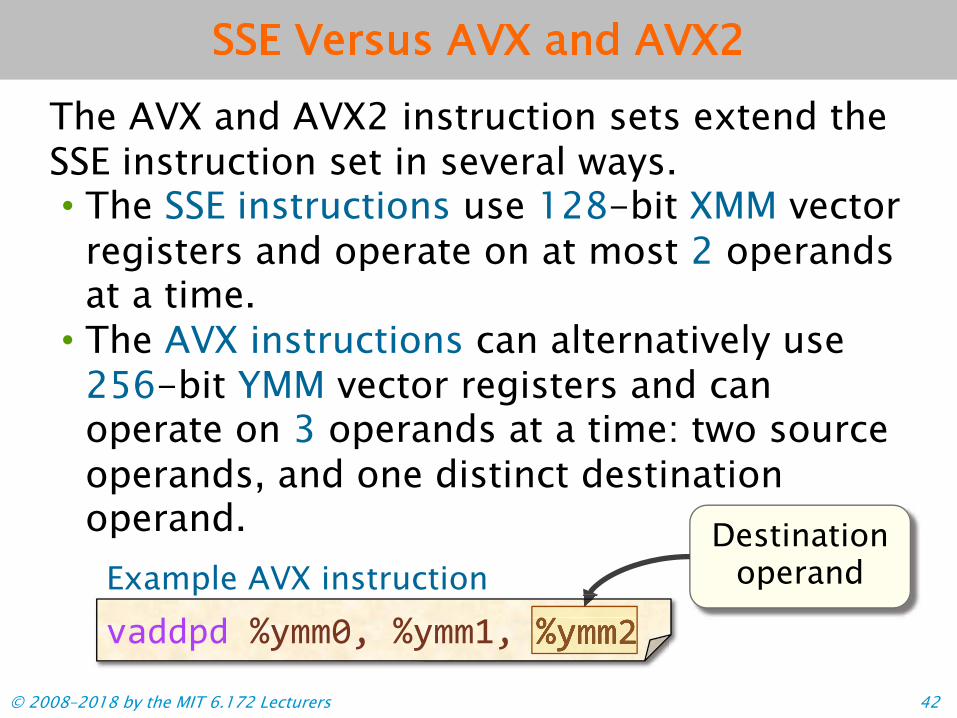
SSE Versus AVX and AVX2
The AVX and AVX2 instruction sets extend the SSE instruction set in several ways. ! The SSE instructions use 128-bit XMM vector
registers and operate on at most 2 operandsat a time.! The AVX instructions can alternatively use
256-bit YMM vector registers and canoperate on 3 operands at a time: two sourceoperands, and one distinct destination
!"##$# %&''()*%&''+)*%&'',
operand.
Example AVX instruction Destination
operand
%&''()*%&''+)*%&'',%&''()*%&''+)*%&'',
© 2008–2018 by the MIT 6.172 Lecturers 42

SSE and AVX Vector Opcodes
Many of the SSE and AVX opcodes are similar to traditional x86-64 opcodes, with minor differences.
Example: Opcodes to add 64-bit values
© 2008–2018 by the MIT 6.172 Lecturers
SSE AVX/AVX2 Floating-point !""#" $!""#"
Integer #!""% $#!""%
The “$” prefixdistinguishes the
AVX/AVX2 instruction.
2018 by the MIT 6.172 Lecturers
The “#” prefixdistinguishes an integer vector instruction.
$#!""%$!""#"$!""#"$#!""%$#!""%#!""%
43

Vector-Register Aliasing
Like the general-purpose registers, the XMM and YMM vector registers are aliased.
XMM/YMM vector-register layout !"##$
!%##$
High 128 bits Low 128 bits
© 2008–2018 by the MIT 6.172 Lecturers 44

!"##$ %&'&(
"#)*+)$#)*+,*-./01 !
© 2008–2018 by the MIT 6.172 Lecturers 45
OVERVIEW OF COMPUTER ARCHITECTURE

A Simple 5-Stage Processor
Instr. memory
Ad
d
PC
GPRs
IR
Data memory
Instruction Fetch (IF)
Instruction Decode (ID)
Execute (EX)
Memory (MA)
Write back (WB)
Instr. size
Bypasses
Bypasses
ALU
© 2008–2018 by the MIT 6.172 Lecturers 46

Block Diagram of 5-Stage Processor IF ID EX MA WB
Fetch unit Decode ALU Data
mem. GPRs WB
Each instruction is executed through 5 stages: 1. Instruction fetch (IF): Read instruction from memory. 2. Instruction decode (ID): Determine which units to use
to execute the instruction, and extract the register arguments.
3. Execute (EX): Perform ALU operations. 4. Memory (MA): Read/write data memory. 5. Write back (WB): Store result into registers.
© 2008–2018 by the MIT 6.172 Lecturers 47
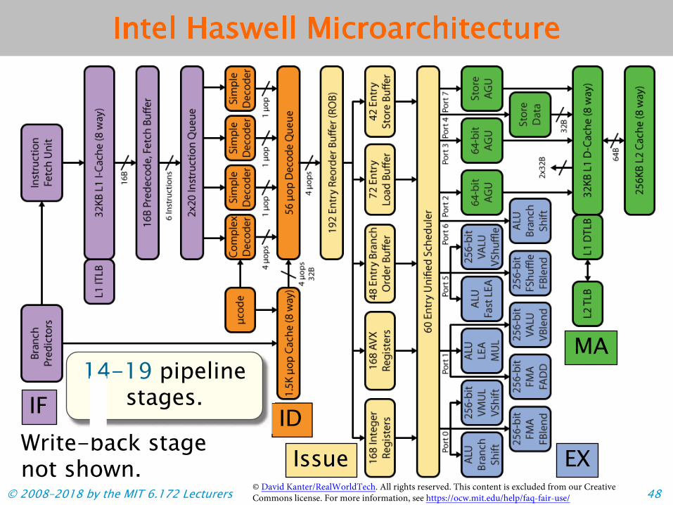
Intel Haswell Microarchitecture
IF ID
Issue EX
MA
Write-back stage not shown.
back stage back stage
14-19 pipelinestages.
© David Kanter/RealWorldTech. All rights reserved. This content is excluded from our Creative © 2008–2018 by the MIT 6.172 Lecturers Commons license. For more information, see https://ocw.mit.edu/help/faq-fair-use/ 48

Bridging the Gap
This lecture bridges the gap between the simple 5-stage processor and a modern processor core by examining several design features: • Vector hardware• Superscalar processing• Out-of-order execution• Branch prediction
© 2008–2018 by the MIT 6.172 Lecturers 49

Architectural Improvements
Historically, computer architects have aimed to improve processor performance by two means: ! Exploit parallelism by executing multiple
instructions simultaneously.! Examples: instruction-level parallelism
(ILP), vectorization, multicore.! Exploit locality to minimize data movement.! Example: caching.
This lecture: ILP and vectorization
© 2008–2018 by the MIT 6.172 Lecturers 50

Pipelined Instruction Execution
Processor hardware exploits instruction-level parallelism by finding opportunities to execute multiple instructions simultaneously
Instr. # Cycle
1 2 3 4 5
i IF EX MA
Ideal pipelined timing Ins cclle e
.
tr. # Cy
1 2 3 4 5
i IF EX MA
EX MA WB
MA WB
EX MA WB
in different pipeline stages
MA
in different pipeline stages.
Pipelining improves processor throughput. © 2008–2018 by the MIT 6.172 Lecturers 51
e
in different pipeline stages.
66 77 88 99
in different pipeline stages. Each pipeline stage
is executing a d
ifferen
t inst
ructi
on.
IDID WB WBWB
ii+1+1 IF ID
ii+2+2 IF ID
ii+3+3 IF
ii+4+4 ID EX MA WB
EXEX
IDID
IFIF

Pipelined Execution in Practice
In practice, various issues can prevent an instruction from executing during itsdesignated cycle, causing the processor pipeline to stall.
Instr. # Cycle
1 2 3 4 5 6
EX MA
ID EX MA
i+2 ID EX MA WB
IF
ID
Pipeline stalls
© 2008–2018 by the MIT 6.172 Lecturers 52
7 8 9
i IF ID WB
i+1 IF ID WB
i+3
IDID
IFIF IFIF
IFIF IFIF IFIF
IF
ID IDID IDID ID
IFIF IFIF IF IFIF IFIF IF
IFIF IF IFIF IFIFIF IF IFIFIF IF IFIF IFIFIF IF IFIF IF IFIF IFIFIF IF
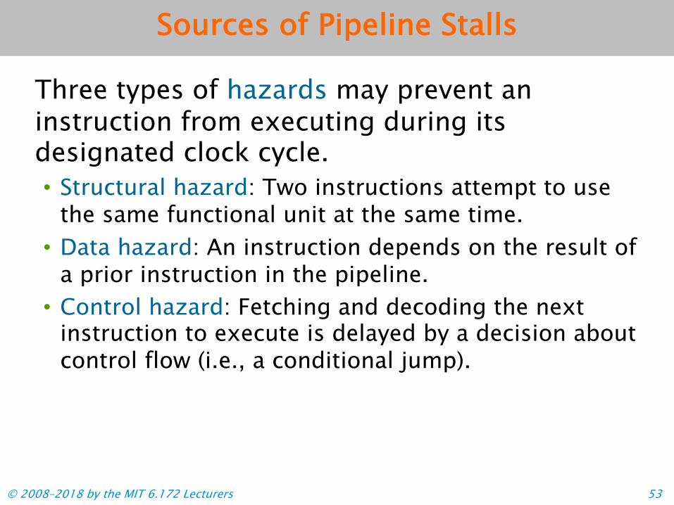
Sources of Pipeline Stalls
Three types of hazards may prevent an instruction from executing during its designated clock cycle. • Structural hazard: Two instructions attempt to use
the same functional unit at the same time.• Data hazard: An instruction depends on the result of
a prior instruction in the pipeline.• Control hazard: Fetching and decoding the next
instruction to execute is delayed by a decision aboutcontrol flow (i.e., a conditional jump).
© 2008–2018 by the MIT 6.172 Lecturers 53

%&'()$%!'
Sources of Data Hazards An instruction i can create a data hazard with a later instruction j due to a dependence between i and j. ! True dependence (RAW):
Instruction i writes a location that instruction j reads.
! Anti-dependence (WAR): Instruction i reads a location that instruction j writes.
! Output-dependence (WAW): Both instructions i and j write to the same location.
!""# $%&'()$%!' *+&# $%!'()$%,'
!""# $%&'()$%!' *+&# $%,'()$%&'
-./# 0'0()$%!' -./# 0'1()$%!'
%&'()$%!'%&'()$%!'%&'()$%!'$%!'()$%,'$%!'()$%,'
$%&'()$%!'%&'()$%!'$%,'()$%&'
0'0()$%!'0'1()$%!'
%&'()$%!'
$%!'()$%,'
© 2008–2018 by the MIT 6.172 Lecturers 54

Complex Operations Some arithmetic operations are complex to implement in hardware and have long latencies.
Operations Example x86-64 opcodes
Latency (cycles)
Most integer arithmetic, logic, shift
!""#$%&'# !("#$)*#$ +)*#$%!*#$%!,#$,-!.
1
Integer multiply /&,#$0/&, 3 Integer division "01#$0"01 variable
Floating-point add !""%%#$!""%" 3 Floating-point multiply /&,%%#$/&,%" 5 Floating-point divide "01%%#$"01%" variable Floating-point fma 12/!%%#$12/!%" 5
How can hardware accommodate these complex operations?
© 2008–2018 by the MIT 6.172 Lecturers 55

Complex Pipelining Idea: Use separate functional units for complex operations, such as floating-point arithmetic.
© 2008–2018 by the MIT 6.172 Lecturers 56
Fetch unit
Data mem. GPRs Decode
FAdd
WB
WBALU
Separate registers, e.g., XMM.
© 2008–2018 by the MIT 6.172 Lecturers
Functional units might be pipelined fully, partially, or
not at all.
FPRs
FDiv
FMul
56
Unpipelined division

Intel Haswell Functional Units
Haswell uses a suite of integer, vector, and floating-point functional units, distributed among 8 different ports.
© 2008–2018 by the MIT 6.172 Lecturers 57
Issue
EX
MA
© David Kanter/RealWorldTech. All rights reserved. This content is excluded from our Creative Commons license. For more information, see https://ocw.mit.edu/help/faq-fair-use/

From Complex to Superscalar Given these additional functional units, how can the processor further exploit ILP?
Fetch unit
Data mem. GPRs Decode
FAdd
WB
WBALU
FPRs
FDiv
FMul
IDEA: Fetch and issue multiple
instructions per cycle to keep
the units busy.
© 2008–2018 by the MIT 6.172 Lecturers 58

Intel Haswell Fetch and Decode
Haswell break up x86-64 instructions into simpler operations, called micro-ops.
!"# $#%!&'$#%!
! The fetch and decodestages can emit 4micro-ops per cycle tothe rest of the pipeline.
! The fetch and decodestages implementoptimizations onmicro-op processing,including special casesfor common patterns,e.g.,
IF
ID
© David Kanter/RealWorldTech. All rights reserved. This content is excluded from our Creative © 2008–2018 by the MIT 6.172 Lecturers Commons license. For more information, see https://ocw.mit.edu/help/faq-fair-use/ 59

Bridging the Gap
• Vector hardware• Superscalar processing• Out-of-order execution• Branch prediction
© 2008–2018 by the MIT 6.172 Lecturers 60

Block Diagram of a Superscalar Pipeline
The issue stage in the pipeline manages the functional units and handles scheduling of instructions.
IF ID WB
ALU Issue Data Mem
What does the issue stage do to exploit ILP?
FAdd
FMul
FDiv
© 2008–2018 by the MIT 6.172 Lecturers 61

Bypassing allows an instruction to read its Example arguments before they’ve been stored in a GPR.
Without bypassing
!""# $%&'()$%!' *+&# $%!'()$%,'
()$%!'()$$%!'()$%,'$%!'()$%,'
1
2
EX
WB
Instr. # Cycle
1 2 3 4 5 6
1 IF ID EX MA WB
2 IF ID ID ID EX MA WB
*+&# $%!'()$%,'$%!'()$%,'$%!'()$%,'$%!'()$%,'*+&# $%!'()$%,'
With bypassing Instr. # Cycle
1 2 3 4 5 6 7 8 9
1 IF ID EX MA WB
2 IF ID EX MA WB WBWB
Stall eliminated.EX
EX
MA WB
© 2008–2018 by the MIT 6.172 Lecturers 62
Bypassing
Stall waiting for %rax to be writtenback to a register.

Data Dependencies: Example
What else can the hardware do to exploit ILP? Let’s consider a larger code example with more data dependencies. Example instruction stream # Instruction Latency
1 !"#$% &'()*+,-'*!!. 2
2 !"#$% &'(/*+,-'*!!0 5
3 !12$% '*!!., '*!!0 3
4 )%%$% '*!!., '*!!3 1
5 )%%$% '*!!3,-'*!!3 1
6 !12$% '*!!3,-'*!!. 3
Latencies chosen to simplify example.
'*!!0'*!!0
&'(/*+,-'*!!0
&'()*+,-'*!!.&'()*+,-'*!!.!"#$%
&'()*+,-'*!!.
!12$%
Simplifyingassumptions ! The issue stage issues
1 operation per cycle. ! The processor has
plenty of functionalunits for alloperations.
! We’ll ignore the non-execute stages of thepipeline.
&'()*+,-'*!!.&'()*+,-'*!!.!"#$%
!12$%)%%$%
&'()*+,-'*!!.!"#$%
'*!!0
'*!!3,-'*!!3'*!!3,-'*!!3'*!!3
'*!!3,-'*!!.'*!!3,-'*!!3'*!!3,-'*!!3'*!!3,-'*!!3)%%$%
!12$%
&'()*+,-'*!!.&'()*+,-'*!!.&'()*+,-'*!!.&'()*+,-'*!!.&'()*+,-'*!!.&'()*+,-'*!!.
'*!!3,-'*!!.
)%%$%
)%%$%)%%$%'*!!3,-'*!!.'*!!3,-'*!!.'*!!3,-'*!!.
!12$%
)%%$%)%%$%)%%$%)%%$%)%%$%
'*!!3,-'*!!.'*!!3,-'*!!.'*!!3,-'*!!.'*!!3,-'*!!.'*!!3,-'*!!.'*!!3,-'*!!.'*!!3,-'*!!.'*!!3,-'*!!.'*!!3,-'*!!.'*!!3,-'*!!.'*!!3,-'*!!.'*!!3,-'*!!.'*!!3,-'*!!3'*!!3,-'*!!.'*!!3,-'*!!.
'*!!.,'*!!.,'*!!.,'*!!.,
assumptionsThe issue stage issues
operation per cycle.
n
5
assumptionsThe issue stage issues1 operation per cycle.
RAW dependence
plenty of functionalunits for alloperations.operations.
plenty of functionalunits for alloperations.
WAR dependence
'*!!3,-'*!!.'*!!3,-'*!!3
'*!!3,-'*!!.'*!!3,-'*!!.'*!!3,-'*!!.'*!!3,-'*!!.
2
© 2008–2018 by the MIT 6.172 Lecturers 63

Example: In-Order Issue
Instruction stream
If the hardware must issue all instructions in order, how long does execution take?
# Instruction Latency
© 2008–2018 by the MIT 6.172 Lecturers 64
Instr.# 1 3
456
Instr. # 1 3
X X
X X 4 5 X 6
Instruction timing for
use of functional
units
6
X
X
3
XX
Data dependence.
1 !"#$% &'()*+,-'*!!. 2 2 !"#$% &'(/*+,-'*!!0 5 3 !12$% '*!!., '*!!0 3 4 )%%$% '*!!., '*!!3 1 5 )%%$% '*!!3,-'*!!3 1 6 !12$% '*!!3,-'*!!. 3
11 22 33
Can the hardware do better?
22 1010 1111 1212 Dependence from in-order issue.
X X X X X X
X
X X X

Data-Flow Graphs
We can model the data dependencies between instructions as a data-flow graph.
# Instruction Latency
1 !"#$% &'()*+,-'*!!. 2
2 !"#$% &'(/*+,-'*!!0 5
3 !12$% '*!!., '*!!0 3
4 )%%$% '*!!., '*!!3 1
5 )%%$% '*!!3,-'*!!3 1
6 !12$% '*!!3,-'*!!. 3
Example instruction stream
1 2
3
5 6
4
RAW dependence
c
m
WAR dependence
'*!!3,-'*!!3
+,-'*!!.
'*!!0'*!!.,'*!!.,
'*!!3,-'*!!.'*!!3,-'*!!.
'*!!3
!12$%
)%%$%)%%$%
'*!!3,-'*!!.'*!!3,-'*!!.'*!!3,-'*!!.'*!!3,-'*!!.
)%%$%
)%%$%)%%$%)%%$%'*!!3,-'*!!.'*!!3,-'*!!.'*!!3,-'*!!.'*!!3,-'*!!.'*!!3,-'*!!.'*!!3,-'*!!.'*!!3,-'*!!.'*!!3,-'*!!.'*!!3,-'*!!.'*!!3,-'*!!.'*!!3,-'*!!.
Instruction
© 2008–2018 by the MIT 6.172 Lecturers 65

In-Order Issue, Revisited
© 2008–2018 by the MIT 6.172 Lecturers 66
Instruction stream
Instr. #
Cycle 1 2 3 4 5 6 7 8 9 10 11 12
1 X X2 X X X X X 3 X X X 4 X 5 X 6 X X X
Instruction timing for
use of functional
units
# Instruction Latency 1 !"#$% &'()*+,-'*!!. 2 2 !"#$% &'(/*+,-'*!!0 5 3 !12$% '*!!., '*!!0 3 4 )%%$% '*!!., '*!!3 1 5 )%%$% '*!!3,-'*!!3 1 6 !12$% '*!!3,-'*!!. 3
X
X
+,-'*!!0'*!!.,'*!!.,'*!!3,-'*!!3'*!!3,-'*!!.6 !12$% '*!!3,-'*!!.
(/*+,-'*!!0'*!!.,'*!!.,'*!!3,-'*!!3
6 !12$% '*!!3,-'*!!.
False dependence!Instruction 4
doesn’t depend on instructions 2 or 3!
I 1
XX
c l e
X
'*!!3
3
X
1 2
3
5 6
4
Cy
'*!!3
3
'*!!3
Data-flow graph

6 6
units
Example: Out-of-Order Execution Instruction
Idea: Let the stream hardware issue an instruction as soon as its data dependencies are satisfied.
# Instruction Latency
© 2008–2018 by the MIT 6.172 Lecturers 67
Instruction timing for
use of functional
units
Instr. #
Cycle 1 2 3 4 5 6 7 8 9 10 11 12
1 X X 2 X X X X X 34 5
X X
units
6
Can the hardware do better?
X X
Instructions 4 and 5 execute much earlier.
1 !"#$% &'()*+,-'*!!. 2 2 !"#$% &'(/*+,-'*!!0 5 3 !12$% '*!!., '*!!0 3 4 )%%$% '*!!., '*!!3 1 5 )%%$% '*!!3,-'*!!3 1 6 !12$% '*!!3,-'*!!. 3
X X X X
X X X X

Eliminating Name Dependencies
© 2008–2018 by the MIT 6.172 Lecturers 68
# Instruction Latency
1 !"#$% &'()*+,-'*!!. 2
2 !"#$% &'(/*+,-'*!!0 5
3 !12$% '*!!., '*!!0 3
4 )%%$% '*!!., '*!!3 1
5 )%%$% '*!!3,-'*!!3 1
6 !12$% '*!!3,-'*!!. 3
Instruction stream
1 2
3
5 6
4
Idea: If the name of the destination register could be changed, then the
WAR dependencies could be eliminated.
Data-flow graph
'*!!.,'*!!.,
'*!!3,-'*!!.
)%%$%)%%$%)%%$%)%%$%
'*!!3,-'*!!.'*!!3,-'*!!.'*!!3,-'*!!.'*!!3,-'*!!.
!12$%!12$%)%%$%)%%$%)%%$%)%%$%
'*!!3,-'*!!.'*!!3,-'*!!.)%%$%
'*!!3,-'*!!.'*!!3,-'*!!.'*!!3,-'*!!.'*!!3,-'*!!.
1 2
3
5 6
4
New data-flow graph
Instruction 6 no longerdepends on long
latency operations!

Instr.#
Cycle
4 7 12
Instr. #
Cycle
4 7 12
order execution,
© 2008–2018 by the MIT 6.172 Lecturers 69
Instruction timing for
use of functional
units
1 X X
2 X X X X X
3 X X X
4 X
5 X
6 X X X
1 X X
2 X X X X X
3 X X X
4 X
5 X
6 X X X
X
X X X XX X
Combined with out-of-
can all execute earlier.
X
Effect of Eliminating Name Deps.
New data-flow graph
Idea: Let the hardware change destinationregister names on the fly.
1 2
3
5 6
4
11 22 33 instructions 4, 5, and 6

Removing Data Dependencies
The processor mitigates the performance loss of data hazards using two techniques. • Register renaming removes WAR and WAW
dependencies.• Out-of-order execution reduces the
performance lost due to RAW dependencies.
© 2008–2018 by the MIT 6.172 Lecturers 70

On-the-Fly Register Renaming How does hardware overcome WAR and WAW dependencies?Idea: Architecture implements many more physical registers than registers specified by the ISA. Renaming table List of free physical registers ISA Reg. Data
© 2008–2018 by the MIT 6.172 Lecturers 71
xmm0 Preg7
xmm1 Preg4
xmm2 Preg2
xmm3
Preg3 Preg8 Preg1 Preg0 …
Maintains a mapping from ISA registers to physical registers.

Dynamic Instruction Reordering The issue stage tracks the data dependencies between instructions dynamically using a circular buffer, called a reorder buffer (ROB).
Sketch of a Reorder buffer Tag Instr. # OP Source 1 Source 2 Dest.
t1 1 movsd Preg7 t2 2 movsd Preg2 t3 3 mulsd t1 t2 t4 t5 t6 t7
Actual ROB hardware is more complex. © 2008–2018 by the MIT 6.172 Lecturers 72

Dynamic Reordering and Renaming: Example
Instruction 2 Initial state: stream 5 Instructions 2 3 and 3 are %rip
# Instruction Latency 1 movsd (%rax), %xmm0 2 movsd (%rbx), %xmm2 3 mulsd %xmm0, %xmm2 4 addsd %xmm0, %xmm1 5 addsd %xmm1, %xmm1 6 mulsd %xmm1, %xmm0
executing. 1
Reorder buffer
Renaming table ISA Reg. Data
xmm0
xmm1 Preg4
xmm2
Tag Instr. # OP Source 1 Source 2 Dest.
© 2008–2018 by the MIT 6.172 Lecturers 73
t1 1 movsd Preg7 t2 2 movsd Preg2
t1 t3 t4 t5t2 t6
xmm3 t7
1
3

Instruction stream
# Instruction Latency
Step: Decode instruction 3.!"#$
Reorder buffer
Dynamic Reordering and Renaming: Example
1 %&'() *!"+,-./!,%%0 2 2 %&'() *!"1,-./!,%%2 5 3 %34() !,%%0. !,%%2!,%%0. 3 4 +))() !,%%0. !,%%5 1 5 +))() !,%%5./!,%%5 1 6 %34() !,%%5./!,%%0 3
!,%%2
Renaming table Tag Instr. # OP Source 1 Source 2 Dest.
ISA Reg.
xmm0 t1x
Data
xmm1 Preg4
mm0 t1
xmm3
t1 1 movsd Preg7 t2 2 movsd Preg2 t3 3 mulsd t1 t2t4 t5 t6 t7
t1 t2
© 2008–2018 by the MIT 6.172 Lecturers 74
xxmmmm2 2 t2 t2xxxmmmm2 mm2 mm2 2m2 t2 t2 t2t2

© 2008–2018 by the MIT 6.172 Lecturers 75
ISA Reg. Data
xmm1 Preg4
xmm2 t2
xmm3
Dynamic Reordering and Renaming: Example
ISA Reg. Data
xmm1 Preg4
xmm2 t3
xmm3
Renaming table
Reorder buffer
!"#$
# Instruction
!,%%2!,%%2
Latency 1 %&'() *!"+,-./!,%%0 2
3 %34() !,%%0. 3 4 +))() !,%%0. !,%%5 1
6 %34() !,%%5./!,%%0
Tag Instr. # OP Source 1 Source 2 Dest. t1 1 movsd t2 2 movsd
Instruction stream
Step: Decode instruction 3.
ORenaming table Tag #Instr. ORenaming table
Update mapping inrenaming table.
4
t3
2 %&'() *!"1,-./!,%%2 5
5 +))() !,%%5./!,%%5 1 3
xxmmmm00 t1t1
Preg7 Preg2
t3 3 mulsd t1 t2 t4 t5 t6 t7
t2 t3t2 t3t2 t3

Instruction stream
# Instruction Latency
Step: Decode instruction 4.
!"#$
Reorder buffer
Dynamic Reordering and Renaming: Example
1 %&'() *!"+,-./!,%%0 2 2 %&'() *!"1,-./!,%%2 5 3 %34() !,%%0. !,%%2 3 4 +))() !,%%0. !,%%5!,%%0. 1 5 +))() !,%%5./!,%%5 1 6 %34() !,%%5./!,%%0 3
!,%%5
ISA Reg.
xm 0 t1
xmm1 Preg4
x
Data
mmm0 t1
xmm1 Preg4
Renaming table Tag Instr. # OP Source 1 Source 2 Dest. t1 1 movsd Preg7
t3
xmm3
xmm2
t3 3 mulsd t1 t2 t4 4 addsd t1 Preg4t5
t1 Preg4
t6 t7
© 2008–2018 by the MIT 6.172 Lecturers 76
t2 2 movsd Preg2

Dynamic Reordering and Renaming: Example
!,%%5
© 2008–2018 by the MIT 6.172 Lecturers 77
ISA Reg. Data
xmm0 t1
xmm1 Preg4
xmm2 t3
ISA Reg. Data
xmm0 t1
xmm1 Preg4
xmm2 t3
ISA Reg. Data
xmm0 t1
xmm1 t4
xmm2 t3
Renaming table
Reorder buffer
!"#$
# Instruction Latency 1 %&'() *!"+,-./!,%%0 2
6 %34() !,%%5./!,%%0
Tag Instr. # OP Source 1 Source 2 Dest. t1 1 movsd Preg7 t2 2 movsd t3 3 mulsd t1 t2
t6
Instruction stream
Step: Decode instruction 4.
ORenaming table Tag #Instr. ORenaming table
Update mapping inrenaming table.
t4
!,%%5
3 %34() !,%%0. !,%%2 3 4 +))() !,%%0. 1
2 %&'() *!"1,-./!,%%2
5 +))() !,%%5./!,%%5
5
1 3
xxxmmmmmm333
Preg2
t4 4 addsd t1 Preg4 t5
t7
a
Dynamic Reordering and Renaming: Example
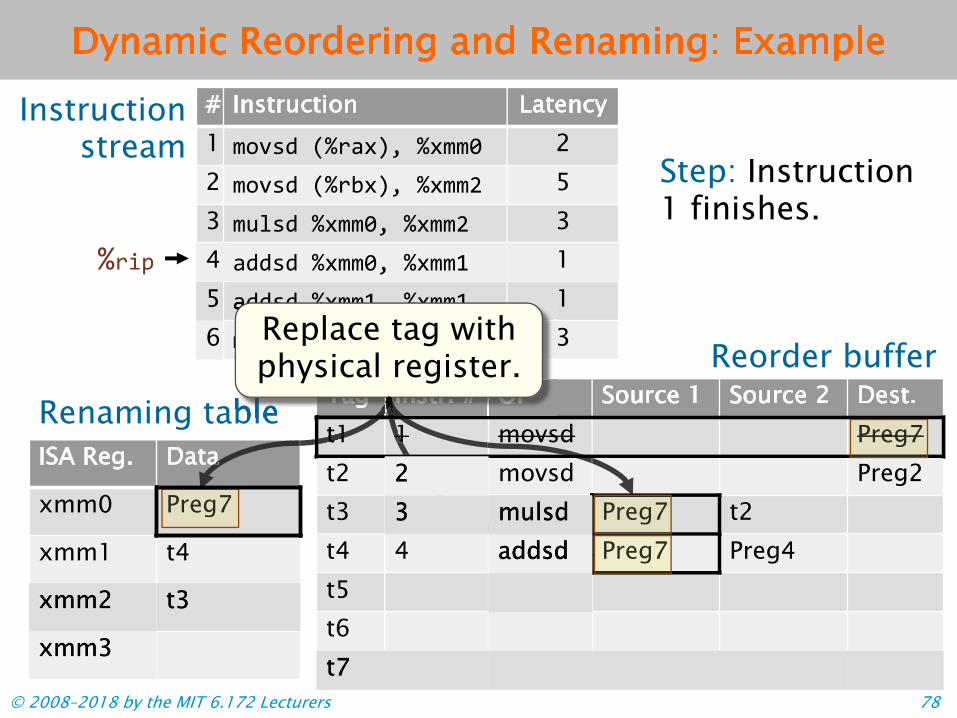
© 2008–2018 by the MIT 6.172 Lecturers 78
ISA Reg. Data
xmm0 t1
xmm1 t4
Tag Instr. # OP Source 1 Source 2 Dest.t1 1 movsd Preg7t2 movsd Preg2t3 t1 t2t4 4 t1 Preg4t5t6
ISA Reg. Data
xmm0 Preg7
xmm1 t4
Renaming table
Reorder buffer
!"#$
# Instruction Latency 1 %&'() *!"+,-./!,%%0 2 2 %&'() *!"1,-./!,%%2 5 3 %34() !,%%0. !,%%2 3
+))() !,%%5./!,%%5 1
%34() !,%%5./!,%%0 3
Tag Instr. # OP Source 1 Source 2 Dest. t1 1 movsd Preg7t2 movsd Preg2 t3 Preg7 t2 t4 4 Preg7 Preg4 t5 t6
Instruction stream
Step: Instruction 1 finishes.
Preg7 Preg7 Preg7
+))()
Renaming tableRenaming table Instr. # OP
+))()
Renaming table Tag
Replace tag withphysical register.
a t1 1 Preg7
4 +))() !,%%0. !,%%5 1 5 6
xxmmmm22 t3t3
xxmmmm33
22 33 mumullsdsd
aaddddddsssd dd
t7t7

Dynamic Reordering and Renaming: Example
© 2008–2018 by the MIT 6.172 Lecturers 79
Tag Instr. # OP Source 1 Source 2 Dest.t1 1 movsd
movsd Preg2t3 3 mulsd Preg7 t2t4 4 addsd Preg4t5t6
ISA Reg. Data
xmm0 Preg7
xmm1 t4
Renaming table
Reorder buffer
!"#$
# Instruction Latency 1 %&'() *!"+,-./!,%%0 2 2 %&'() *!"1,-./!,%%2 5 3 4 1 5 +))() !,%%5./!,%%5 1 6 %34() !,%%5./!,%%0 3
Tag Instr. #
PrP
OP Source 1 Source 2 Dest. t1 1 movsd
movsd eg2 t3 3 mulsd Preg7 t2 t4 4 addsd Preg4 Preg3t5 t6
Instruction stream
Step: Instruction 1 finishes.
addsd Preg4
5 +))() !,%%5./!,%%5
ORenaming table Tag Instr. # ORenaming table
Instruction 4 is ready to execute out of order.
t3 Preg3
urce 2 Dest
113
Source 1 So 2Reorder buffer
S S
Get the next available physical register from
the free list. o u
r
o
%34() !,%%0. !,%%2 3
+))() !,%%0. !,%%5
PPrregeg77 t2 t2t2 22
PPPrrregegeg7 77
t7t7
xmm2 t3
xmm3

Dynamic Reordering and Renaming: Example
Instruction stream
# Instruction Latency 1 %&'() *!"+,-./!,%%0 2
3 %34() !,%%0. !,%%2 3
5 +))() !,%%5./!,%%5 1 6 %34() !,%%5./!,%%0 3
!,%%5./!,%%5!,%%5./!,%%5
1 +))() !,%%0.
5 *!"1,-./!,%%2 2
Step: Decode instruction 5.
%&'()
4 !,%%5
!"#$
Reorder buffer
Renaming table Tag Instr. # OP Source 1 Source 2 Dest.
ISA Reg. Data
xmm0 Preg7
xmm1 t4
xmm2 t3
xmm3
xmm1 t4
t1 1 movsd Preg7 t2 2 movsd Preg2 t3 3 mulsd Preg7 t2 t4 4 addsd Preg7 Preg4 Preg3 t5 5 addsd t4 t4t6 t7
t4 t4
© 2008–2018 by the MIT 6.172 Lecturers 80

Dynamic Reordering and Renaming: Example
© 2008–2018 by the MIT 6.172 Lecturers 81
ISA Reg. Data
xmm0 Preg7
xmm1 t4
xmm2 t3
xmm3
ISA Reg. Data
xmm0 Preg7
xmm1 t5
xmm2 t3
xmm3
Renaming table
Reorder buffer
!"#$
# Instruction Latency 1 %&'() *!"+,-./!,%%0 2 2 %&'() *!"1,-./!,%%2 5 3 %34() !,%%0. !,%%2 3 4 +))() !,%%0. !,%%5 1 5 +))() !,%%5./!,%%5 1 6 %34() !,%%5./!,%%0 3
Tag Instr. # OP Source 1 Source 2 Dest. t1 1 movsd Preg7 t2 2 movsd Preg2 t3 3 mulsd Preg7 t2 t4 4 addsd Preg7 Preg4 Preg3 t5 5 addsd t4 t4 t6 t7
Instruction stream
Step: Decode instruction 5.
!,%%5./!,%%5!,%%5./!,%%5
t5
Omovsd
t2 2 movsdData
Renaming tableData
Update mapping inrenaming table.
7

Dynamic Reordering and Renaming: Example
© 2008–2018 by the MIT 6.172 Lecturers 82
ISA Reg. Data
xmm0 Preg7
xmm1 t4
xmm2 t3
xmm3
Renaming table
Reorder buffer !"#$
# Instruction Latency 1 %&'() *!"+,-./!,%%0 2 2 %&'() *!"1,-./!,%%2 5 3 %34() !,%%0. !,%%2 3 4 +))() !,%%0. !,%%5 1 5 +))() !,%%5./!,%%5 1 6 %34() !,%%5./!,%%0 3
Tag
4
eg7
4 t2 t2t2
Instr. # OP Source 1 Source 2 Dest. t1 1 movsd Preg7 t2 2 movsd Preg2 t3 3 mulsd Preg7 t4 4 addsd Preg7 Preg Preg3 t5 5 addsd t4 t4 t6 6 mulsd t5 Prt7
Instruction stream
Step: Decode instruction 6.
!,%%5./!,%%0!,%%5./!,%%0
xmm1 t4
xmm0 Preg7 movsdmulsd Preg7 t2mulsd Preg7 t2
Renaming: Destination register will be chosen
from free list when instruction is issued.
t2 eg
t5 Preg7

Haswell Renaming and Reordering Haswell uses a reorder buffer and separate register files for integer and vector/floating-point registers. • Haswell implements the ISA’s 16 distinct integer
registers with 168 physical registers. The same ratioholds independently for the AVX registers.
• Conversions between integer and floating-point orvector values involve data movement on chip.
Issue
© David Kanter/RealWorldTech. All rights reserved. This content is excluded from our Creative © 2008–2018 by the MIT 6.172 Lecturers Commons license. For more information, see https://ocw.mit.edu/help/faq-fair-use/ 83

flow graphs# Instruction Latency 1 movsd (%rax), %xmm0 2 movsd (%rbx), %xmm2 3 mulsd %xmm0, %xmm2 4 addsd %xmm0, %xmm1 5 addsd %xmm1, %xmm1 6 mulsd %xmm1, %xmm0
.Instruction
Summary of Reordering and Renaming Summary: Hardware renaming and reordering are effective in practice. • Despite the apparent dependencies in the
assembly code, typically, only truedependencies affect performance.• Dependencies can be modeled using data-
2stream 5 3 1 1 3
1 2
3
5 6
4
Data-flow graph
© 2008–2018 by the MIT 6.172 Lecturers 84

Bridging the Gap
• Vector hardware• Superscalar processing• Out-of-order execution• Branch prediction
© 2008–2018 by the MIT 6.172 Lecturers 85
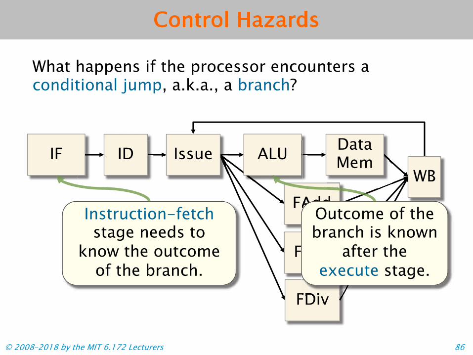
Control Hazards
What happens if the processor encounters a conditional jump, a.k.a., a branch?
IF ID
FAdd WB
ALU
FDiv
FMul
Issue Data Mem
FAddFAdd
FDiv
FAddOutcome of the branch is known
after the execute stage.
Instruction-fetch stage needs to
know the outcome of the branch.
© 2008–2018 by the MIT 6.172 Lecturers 86

Speculative Execution
To handle a control hazard, the processor either stalls at the branch or speculatively executes past it.
When a branch is encountered, assume it’s not taken, and keep executing normally.
!"#$ %&'()*%&+# ,-. /011234 "56$ %&+7)*%&89 "56$ %&+#)*%&:9 !-;;$ +9<-&&-=3>.<
%&9#
Example
© 2008–2018 by the MIT 6.172 Lecturers 87

computation.
Speculative Execution To handle a control hazard, the processor either stalls at the branch or speculatively executes past it. Example
When a branch is encountered, assume it’s not taken, and keep
%&9# executing normally.
If it is later found that the branch was taken, then undo the speculative
© 2008–2018 by the MIT 6.172 Lecturers
!"#$ %&'()*%&+# ,-. /011234 "56$ %&+7)*%&89 "56$ %&+#)*%&:9 !-;;$ +9<-&&-=3>.<
computation.
Problem: The effect on throughput of undoing computation is just like
stalling. computation.On Haswell, a mispredicted branch costs 15-20 cycles.
88

IF
predictors are accurate
Supporting Speculative Execution
Modern processors use branch predictors to increase the effectiveness of speculative execution.
• The fetch stagededicates hardware topredicting theoutcomes of branches.
• Modern branch
over 95% of the time.
© David Kanter/RealWorldTech. All rights reserved. This content is excluded from our Creative © 2008–2018 by the MIT 6.172 Lecturers Commons license. For more information, see https://ocw.mit.edu/help/faq-fair-use/ 89

Simple Branch Prediction
Idea: Hardware maintains a table mapping addresses ofbranch instructions to predictions of their outcomes.
© 2008–2018 by the MIT 6.172 Lecturers 90
Instruction address
Prediction
0x400c0c 00 0x400c1b 00 0x400c47 10 0x400cad 10 0x400cd0 00 0x400ced 00 0x400e37 01 0x400e4e 01 0x400e5c 11 0x400e61 10 0x400e72 10
Encoding Meaning 1 1 Strongly taken 1 0 Weakly taken 0 1 Weakly not taken 0 0 Strongly not taken
A prediction is encoded as a 2-bit saturating counter.
A prediction counter is updated based on the actual outcome of the associated branch: ! Taken " increase counter.!Not taken " decrease counter.

Branch Prediction with Histories
More-complex branch predictors incorporate history information: a record of the outcomes of k recent branches, for a small constant k. ∙ A global history records the outcomes of the most-
recently executed branches on the chip.∙ A local history records the most recent outcomes of
a particular branch instruction.History information can be incorporated into the branch predictor a variety of ways. ∙Map the history directly to a prediction.∙ Combine the history with the instruction address
(e.g., using XOR) and map the result to a prediction.∙ Try multiple strategies and vote on which result to
use at the end.© 2008–2018 by the MIT 6.172 Lecturers 91

Intel Branch Predictor
Not much is publicly known about the con-struction of the branch predictor in Haswell. ∙ A branch-target
buffer (BTB) is used topredict thedestinations ofindirect branches.
∙ Previous Intelprocessors have usedtwo-level predictors,loop predictors, andhybrid schemes.
∙ The branch predictorwas redesigned in
© Via Technologies. All rights reserved. This content is excluded from our Haswell…. Creative Commons license. © 2008–2018 by the MIT 6.172 Lecturers For more information, see https://ocw.mit.edu/help/faq-fair-use/ 92

Summary: Dealing with Hazards
The processor uses several strategies to deal with hazards at runtime: • Stalling: Freeze earlier pipeline stages.• Bypassing: Route the data as soon as it is calculated
to an earlier pipeline stage.• Out-of-order execution: Execute a later instruction
before an earlier one.• Register renaming: Remove a dependence by
changing its register operands.• Speculation: Guess the outcome of the dependence,
and restart the calculation only if guess is incorrect.
© 2008–2018 by the MIT 6.172 Lecturers 93

Further Reading
∙ Intel Corporation. Intel 64 and IA-32 Architectures Software Developer Manuals. 2017.https://software.intel.com/en-us/articles/intel-sdm
∙ Agner Fog. The Microarchitecture of Intel and AMD CPUs. 2017.http://www.agner.org/optimize/microarchitecture.pdf
∙ Intel Corporation. Intel Intrinsics Guide. 2017.
© 2008–2018 by the MIT 6.172 Lecturers 94
MIT OpenCourseWare https://ocw.mit.edu
6.172 Performance Engineering of Software Systems Fall 2018
For information about citing these materials or our Terms of Use, visit: https://ocw.mit.edu/terms.