k.s. school of engineering and management, …
TRANSCRIPT

K.S. SCHOOL OF ENGINEERING AND MANAGEMENT, BANGALORE - 560109
DEPARTMENT OF MECHANICAL ENGINEERING
I SESSIONAL TEST QUESTION PAPER 2018 – 19 ODD SEMESTER
SET-A
USN
Degree : B.E Semester : V
Branch : Mechanical Engineering Date : 4-9-2019
Course Title : Turbo Machines Course Code : 17ME53
Duration : 90 Minutes Max Marks : 30
Note: Answer ONE full question from each part
Q.
No. Question Marks K Level
CO
mapping
PART-A
1(a)
With suitable velocity triangles, derive an expression for maximum
hydraulic efficiency of a Pelton wheel in terms of blade velocity
coefficient and blade discharge angle.
5
K3 Applying
CO1
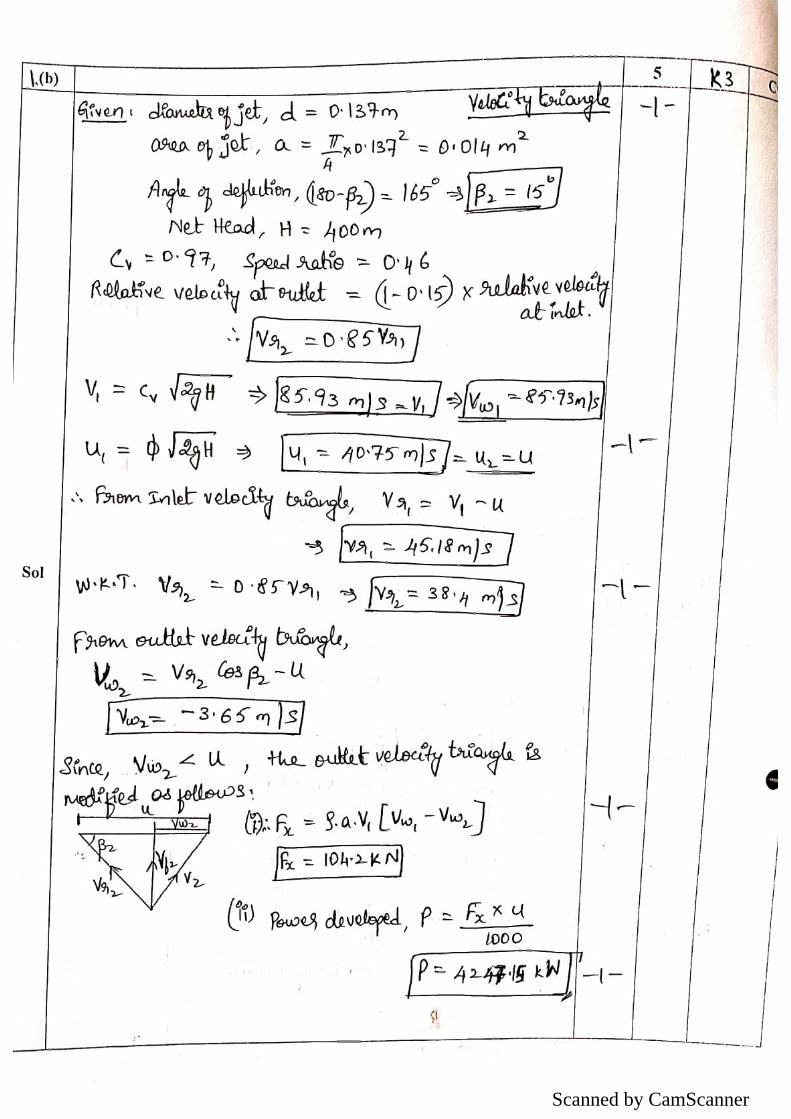
(b)
A 137 mm diameter jet of water issuing from a nozzle impinges on
the buckets of a Pelton wheel and the jet is deflected through an
angle of 165° by the buckets. The head available at the nozzle is
400m. Assuming coefficient of velocity as 0.97, speed ratio as 0.46
and reduction in the relative velocity while passing through the
buckets as 15%, find: (i) Force exerted by the jet on the buckets in
the tangential direction (ii) the power developed.
5
K3
Applying
CO1
(c)
Define a Turbo machine. With a neat sketch explain the parts of a turbo
machine. 5
K2
Understanding
CO2
OR
2(a) Define and explain the following efficiencies of a hydraulic turbine: (i)
Hydraulic efficiency (ii) Mechanical Efficiency (iii) Overall efficiency 5
K2
Understanding
CO1
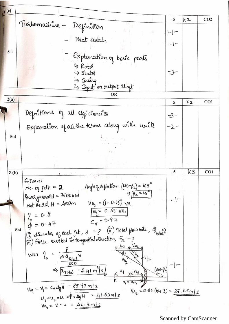
(b)
A double jet Pelton wheel is required to generate 7500kW when the
available head at the base of the nozzle is 400m. The jet is deflected
through 1650 and the relative velocity of the jet is reduced by 15% in
passing over the buckets. Determine: (i) diameter of each jet (ii)
Total flow rate (iii) Force exerted by the jet in the tangential
direction. Assume Overall efficiency = 80%, Speed ratio = 0.47, Cv
= 0.97.
5
K3
Applying
CO1
(c) Explain how turbo machines are classified. 5
K2
Understanding
CO2

PART-B
3(a) Draw a neat sketch of a Francis turbine and explain the functions of each
part. Draw the velocity triangles of a Francis turbine. 5
K2
Understanding CO1
(b)
The following data is given for a Francis turbine: Net head = 70m,
Speed = 600RPM, Shaft power = 368kW, Overall efficiency = 85%,
Hydraulic efficiency = 95%, Flow ratio = 0.25, Breadth ratio = 0.1,
Outer diameter of the runner = 2 x inner diameter of the runner.
Velocity of flow is constant at outlet and inlet. The thickness of the
vanes occupies 10% of the circumferential area of the runner and
discharge is radial at outlet. Determine: (i) Guide blade angle (ii)
Runner vane angles at inlet and outlet (iii) Diameter of runner at
inlet and outlet (iv) width of the runner at inlet.
5
K3
Applying
CO1
(c) Differentiate between a turbo machine and a positive displacement
machine. 5
K2
Understanding CO2
OR
4(a) Draw a neat sketch of a Kaplan turbine and explain the functions of each
part. Draw the velocity triangles of a Kaplan turbine. 5
K2
Understanding CO1
(b)
A Kaplan turbine working under a head of 20m develops 11775kW.
The outer diameter of the runner is 3.5m, hub diameter is 1.75m.
The guide blade angle at the extreme edge of the runner is 350.The
hydraulic and overall efficiencies of the turbine are 0.88 and 0.84
respectively. If the velocity of whirl at outlet is zero, determine: (i)
runner vane angles at inlet and outlet at the extreme edge of the
runner (ii) speed of the turbine.
5
K3
Applying
CO1
(c)
Classify the following as Power generating or Power absorbing turbo
machine: (i) Steam Turbine (ii) Fan (iii) Air blower (iv) Axial flow
compressor (v) Wind Turbine
5
K2
Understanding
CO2
Course In charge Head - Dept Principal

Scanned by CamScanner
Scanned by CamScanner
Scanned by CamScanner

Scanned by CamScanner

Scanned by CamScanner

Scanned by CamScanner

Scanned by CamScanner