kollmorgen frameless motor - bibus.bg · the kbm frameless motor series is our newest direct drive...
TRANSCRIPT
KBM™ Series Brushless Motors
Kollmorgen Frameless Motor Selection Guide

KOLLMORGEN
Kollmorgen. Every solution comes from a real understanding of OEM challenges.The ever-escalating demands of the marketplace mean increased pressure on OEMs at every turn. Time constraints. Demands for better performance. Having to think about the next-generation machine even before the current one is built. While expectations are enormous, budgets are not. Kollmorgen’s innovative motion solutions and broad range of quality products help engineers not only overcome these challenges but also build truly differentiated machines.
Because motion matters, it’s our focus. Motion can distinctly differentiate a machine and deliver a marketplace advantage by improving its performance. This translates to overall increased efficiency for your application. Perfectly deployed machine motion can make your customer’s machine more reliable and efficient, enhance accuracy and improve operator safety. Motion also represents endless possibilities for innovation. We’ve always understood this potential, and thus have kept motion at our core, relentlessly developing products that offer precision control of speed, accuracy and position in machines that rely on complex motion.
K O L L M O R G E N

Table of ContentsuKBM™ Series Frameless Kit Brushless Motor 3
uKBM(S)™ Continuous Torque Overview 7
uKBM(S)™ Motor Data and Dimensions
KBM 10 8
KBM 14 12
KBM 17 16
KBM 25 20
KBM 35 24
KBM 43 28
KBM 45 32
KBM 57 36
KBM 60 40
KBM 79 44
KBM 88 48
KBM 118 52
KBM 163 56
KBM 260 60
uMounting and Installation Guidelines
Safety Notes 64
Package delivered 66
Transport 67
Storage/Operation 68
User Interface Responsibilities 69
Mechanical Installation 70
lnstalling Rotor Inside Stator 73
Electrical Installation 74
uModel Nomenclature 75
uAvailable KBM(S) Modifications 75
K O L L M O R G E N F R A M E L E S S M O T O R S E L E C T I O N G U I D E
Removing the Barriers of Design, Sourcing, and Time At Kollmorgen, we know that OEM engineers can achieve a lot more when obstacles aren’t in the way. So, we knock them down in three important ways:
Integrating Standard and Custom ProductsThe optimal solution is often not clear-cut. Our application expertise allows us to modify standard products or develop totally custom solutions across our whole product portfolio so that designs can take flight.
Providing Motion Solutions, Not Just ComponentsAs companies reduce their supplier base and have less engineering manpower, they need a total system supplier with a wide range of integrated solutions. Kollmorgen is in full response mode with complete solutions that combine programming software, engineering services and best-in-class motion components.
Global FootprintWith direct sales, engineering support, manufacturing facilities, and distributors across North America, Europe, Middle East, and Asia, we’re close to OEMs worldwide. Our proximity helps speed delivery and lend support where and when they’re needed.
Financial and Operational Stability Kollmorgen is part of Danaher Corporation, our $13B parent company. A key driver in the growth of all Danaher divisions is the Danaher Business System, which relies on the principle of “kaizen” – or continuous improvement. Using world-class tools, cross-disciplinary teams of exceptional people evaluate processes and develop plans that result in superior performance.
3w w w. k o l l m o r g e n . c o m

K O L L M O R G E N
KB
M
FR
AM
EL
ES
S
MO
TO
R
KBM™ Series Frameless Kit Brushless MotorThe KBM frameless motor series is our newest direct drive technology. KBM kit models are engineered to provide the high-performance, long life and simple installation that today’s design engineers demand. Optional latching digital Hall effect sensors are pre-aligned and factory installed with added axial rotor length to achieve proper triggering. Choice of insulation allows operation over a wide range of line input voltage. Our detailed selection guide provides a variety of pre-engineered options and configurations that are currently available.
For customized features, contact Kollmorgen to help us understand exactly what you need and how we can further optimize any KBM or engineer a new custom motor solution for the unique requirements of your application. We are experts in providing optimized solutions such as special winding configurations, tailored mounting features, diameter and stack length dimensional adjustments, or material variations.
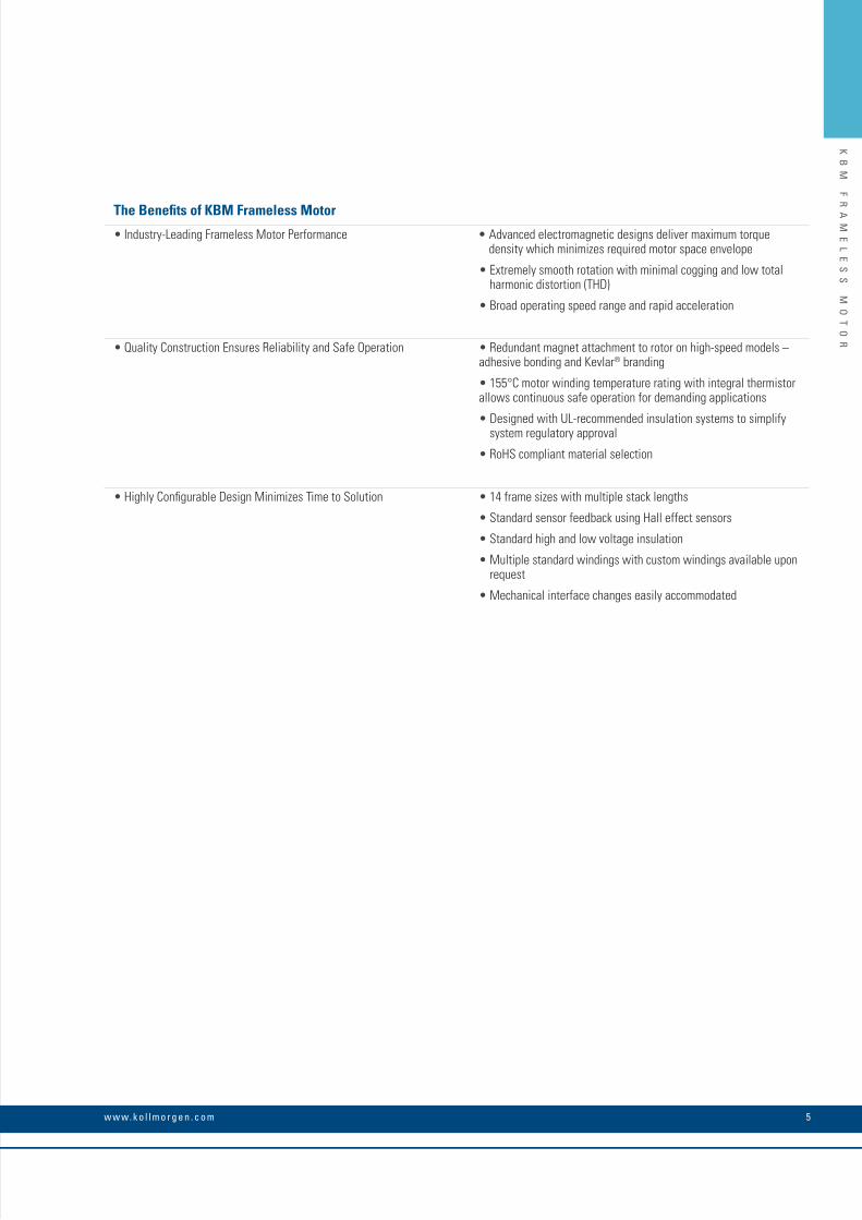
The Benefits of KBM Frameless Motor
• Industry-Leading Frameless Motor Performance • Advanced electromagnetic designs deliver maximum torquedensity which minimizes required motor space envelope
• Extremely smooth rotation with minimal cogging and low total• harmonic distortion (THD)
• Broad operating speed range and rapid acceleration
• Quality Construction Ensures Reliability and Safe Operation • Redundant magnet attachment to rotor on high-speed models – • adhesive bonding and Kevlar® branding
• 155°C motor winding temperature rating with integral thermistor • allows continuous safe operation for demanding applications
• Designed with UL-recommended insulation systems to simplify• system regulatory approval
• RoHS compliant material selection
• Highly Configurable Design Minimizes Time to Solution • 14 frame sizes with multiple stack lengths
• Standard sensor feedback using Hall effect sensors
• Standard high and low voltage insulation
• Multiple standard windings with custom windings available upon • request
• Mechanical interface changes easily accommodated
5w w w. k o l l m o r g e n . c o m
KB
M
FR
AM
EL
ES
S
MO
TO
R

K O L L M O R G E N 6
KB
M
FR
AM
EL
ES
S
MO
TO
R
KBM Series OverviewKollmorgen, the global leader in direct drive motor technology, is pleased to offer KBM series frameless kit brushless motors. With a wide variety of sizes and torque ranges available, KBM models are engineered to provide the high-performance, long life and simple installation that today’s design engineers demand.
Quality Construction
• Fully encapsulated stator windings
• 155°C internal winding temperature continuous capability
• PTC thermistor (avalanche-type) overload protection
• Rare-earth neodymium-iron-boron magnets
• Fail-safe bands over rotor magnets*
• RoHS compliant
Available Options (No engineering fees apply)
Sensor Feedback (KBMS models)Latching digital Hall effect sensors are pre-aligned and factory installed
on the lead end of the stator. Wiring instructions and electrical timing
diagrams are included in this selection guide. KBMS models include
added axial rotor length to achieve proper sensor triggering.
Choice of Insulation System S (standard) – acceptable for applications up to 240 Vac drive
amplifier supply.
H (high voltage) – required for applications >240 Vac and up to
480 Vac drive amplifier supply.
Allowed Modifications See page 78. (Engineering fees apply.
Consult Kollmorgen Customer Support for guidance or to obtain a
quotation. Unit price increase may apply, depending upon extent of
modification.)
Various WindingsMotor windings may be optimized to provide desired speed and torque
performance according to the unique voltage and current requirements
of a customer’s application. Kollmorgen engineers must confirm
electrical feasibility and manufacturability of each special winding
arrangement prior to quotation.
Rotor Hub DimensionsRotor hubs may be provided with different customer-designated hole
patterns, mounting features or smaller inner bore diameters. Standard
KBM(S) models shown within this selection guide include the largest
available inner rotor bore diameter.
Rotor Hub MaterialStandard configuration KBM(S) rotor hubs are constructed from non-
plated cold rolled steel. If plating, coating, cleaning or alternate material
is desired, Kollmorgen engineers must confirm feasibility and pricing
adjustment prior to quotation.
Stator Sleeve MaterialStandard configuration KBM(S)-10, 14, 17, 25, 35, 45, 163 and 260
size stators are designed with uncoated aluminum sleeves around the
stator lamination stack. If coating or plating is desired for the aluminum
stator sleeve, Kollmorgen engineers must confirm feasibility and pricing
adjustment prior to quotation. Stator sleeves are only utilized for the
sizes listed above.
Agency (UL/CE) InformationKBM(S) motors are designed to facilitate UL or CE certification in
the customer’s higher-level assembly. Stator insulation systems are
constructed entirely from agency-approved materials and are designed
in full compliance with agency creepage and clearance dimensional
guidelines. Dielectric strength between winding circuit and grounded
metal stator surface is tested at agency-specified voltage level. Because
a frameless motor’s compliance with agency requirements is dependent
upon correct installation and proper design of the surrounding enclosure
by the user, please review Kollmorgen’s recommended mounting and
installation guidelines on page 70.
* Does not apply to KBM 163 and KBM 260.
7w w w. k o l l m o r g e n . c o m
KB
M(
S)
C
ON
TI
NU
OU
S
TO
RQ
UE
O
VE
RV
IE
W
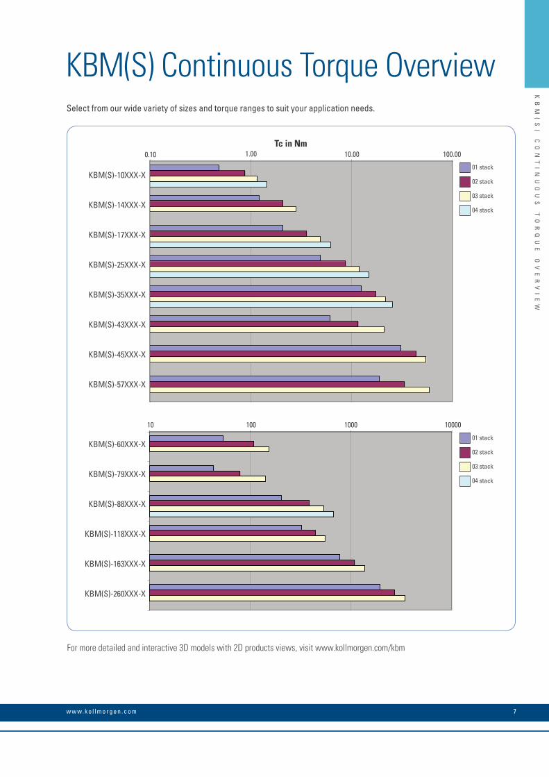
KBM(S) Continuous Torque Overview
Tc in Nm
10.00 100.00 1000.00 10000.00
KBM(S)-60XXX-X
KBM(S)-79XXX-X
KBM(S)-88XXX-X
KBM(S)-118XXX-X
KBM(S)-163XXX-X
KBM(S)-260XXX-X
01 stack02 stack03 stack04 stack
Tc in Nm
0.10 1.00 10.00 100.00
KBM(S)-10XXX-X
KBM(S)-14XXX-X
KBM(S)-17XXX-X
KBM(S)-25XXX-X
KBM(S)-35XXX-X
KBM(S)-43XXX-X
KBM(S)-45XXX-X
KBM(S)-57XXX-X
01 stack02 stack03 stack04 stack
Tc in Nm
10
0.10 10.00
1000 10000100
100.001.00
KBM(S)-10XXX-X
KBM(S)-14XXX-X
KBM(S)-17XXX-X
KBM(S)-25XXX-X
KBM(S)-35XXX-X
KBM(S)-43XXX-X
KBM(S)-45XXX-X
KBM(S)-57XXX-X
KBM(S)-60XXX-X
KBM(S)-79XXX-X
KBM(S)-88XXX-X
KBM(S)-118XXX-X
KBM(S)-163XXX-X
KBM(S)-260XXX-X
01 stack
01 stack
02 stack
02 stack
03 stack
03 stack
04 stack
04 stack
For more detailed and interactive 3D models with 2D products views, visit www.kollmorgen.com/kbm
Select from our wide variety of sizes and torque ranges to suit your application needs.
K O L L M O R G E N 8
KB
M
10
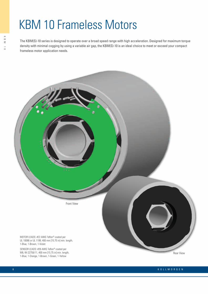
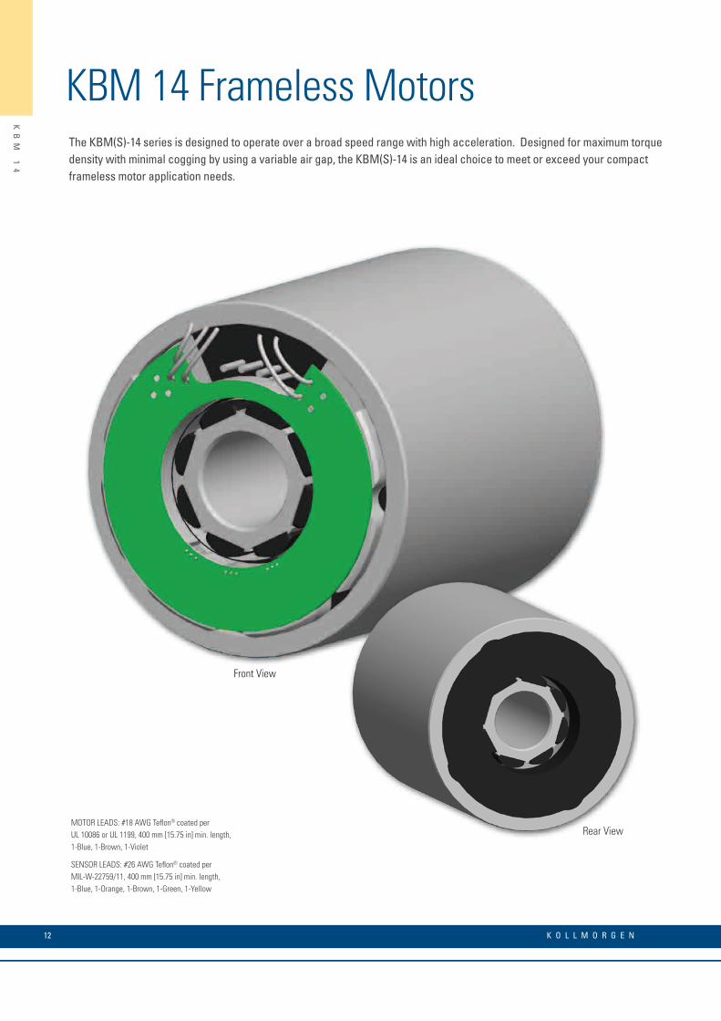
KBM 10 Frameless MotorsThe KBM(S)-10 series is designed to operate over a broad speed range with high acceleration. Designed for maximum torque density with minimal cogging by using a variable air gap, the KBM(S)-10 is an ideal choice to meet or exceed your compact frameless motor application needs.
MOTOR LEADS: #22 AWG Teflon® coated perUL 10086 or UL 1199, 400 mm [15.75 in] min. length,1-Blue, 1-Brown, 1-Violet
SENSOR LEADS: #26 AWG Teflon® coated perMIL-W-22759/11, 400 mm [15.75 in] min. length,1-Blue, 1-Orange, 1-Brown, 1-Green, 1-Yellow
Rear View
Front View

9w w w. k o l l m o r g e n . c o m
KB
M
10
O
UT
LI
NE
D
RA
WI
NG
S
KBM 10 Outline Drawings "A"
STATOR "B"
ROTOR
"D"
"C"
"A"STATOR
"B"ROTOR
"D"
"C"
"E" "A"
STATOR "B"
ROTOR
"D"
"C"
"E"
KBM 10
KBMS 10
Model Number "A" mm[inch] "B" mm[inch] Ø "C" mm[inch] Ø "D" mm[inch]KBM-10X01 46.00 [1.811] 20.14 [.793] 59.963 [2.3607] 16.009 [.6303]KBM-10X02 65.00 [2.559] 39.02 [1.536] 59.963 [2.3607] 16.009 [.6303]KBM-10X03 84.00 [3.307] 57.89 [2.279] 59.963 [2.3607] 16.009 [.6303]KBM-10X04 103.00 [4.055] 76.77 [3.022] 59.963 [2.3607] 16.009 [.6303]
All dimensions are nominal. For more detailed and interactive 3D models with 2D product views, visit www.kollmorgen.com/kbm
Model Number "A" mm[inch] "B" mm[inch] Ø "C" mm[inch] Ø "D" mm[inch] "E" MAX mm[inch]KBMS-10X01 46.00 [1.811] 38.17 [1.503] 59.963 [2.3607] 16.009 [.6303] 5.75 [.226]KBMS-10X02 65.00 [2.559] 57.05 [2.246] 59.963 [2.3607] 16.009 [.6303] 5.75 [.226]KBMS-10X03 84.00 [3.307] 75.92 [2.989] 59.963 [2.3607] 16.009 [.6303] 5.75 [.226]KBMS-10X04 103.00 [4.055] 94.80 [3.732] 59.963 [2.3607] 16.009 [.6303] 5.75 [.226]
All dimensions are nominal. For more detailed and interactive 3D models with 2D product views, visit www.kollmorgen.com/kbm
K O L L M O R G E N 10
KB
M
10
P
ER
FO
RM
AN
CE
C
UR
VE
S
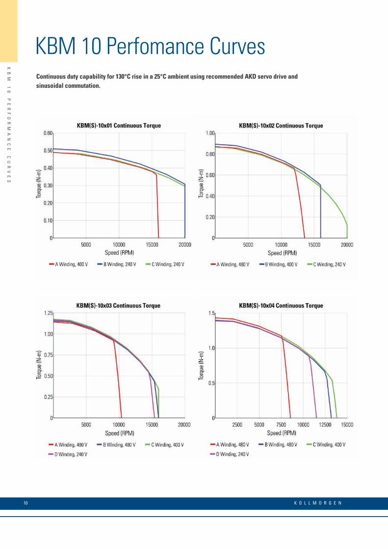
KBM 10 Perfomance CurvesContinuous duty capability for 130°C rise in a 25°C ambient using recommended AKD servo drive and sinusoidal commutation.
11w w w. k o l l m o r g e n . c o m
KB
M
10
P
ER
FO
RM
AN
CE
D
AT
A
KBM 10 Perfomance Data
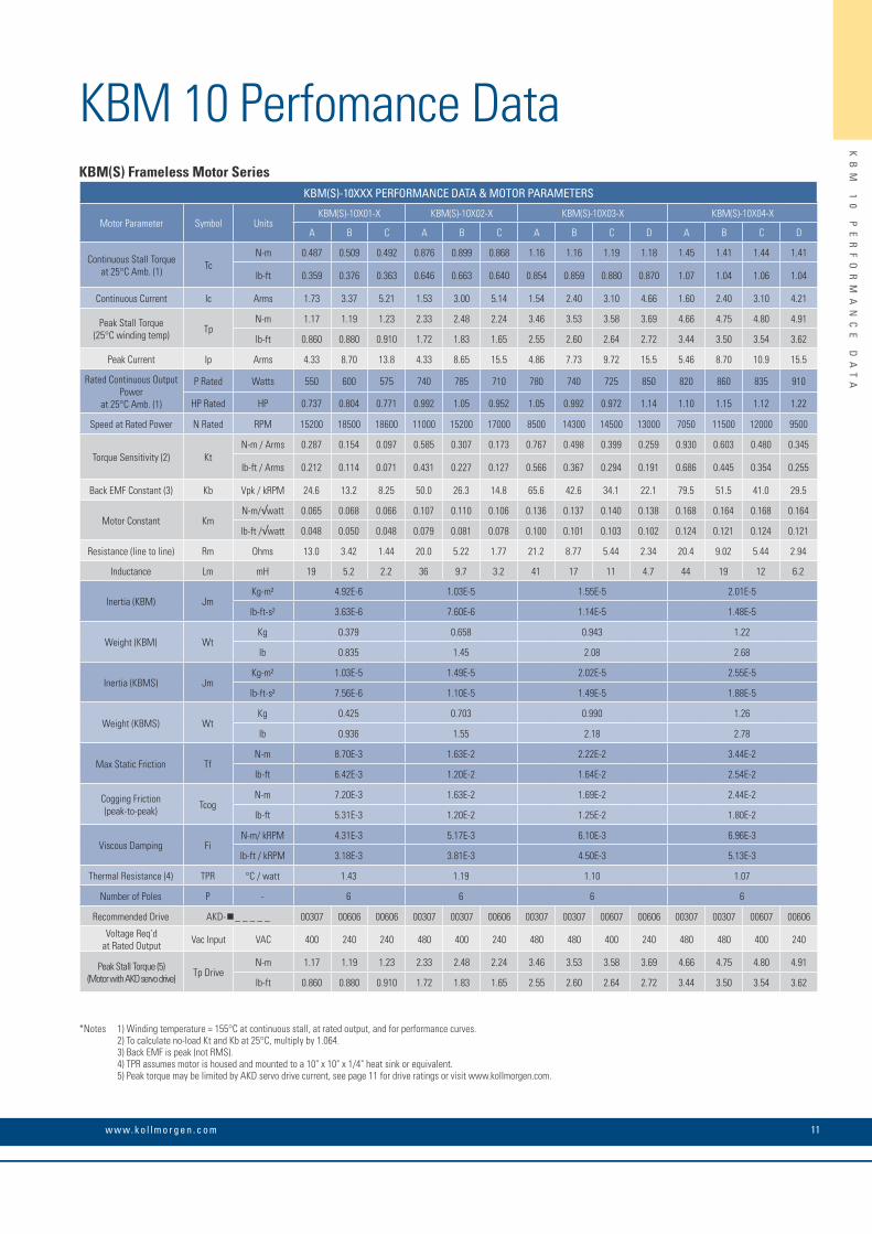
*Notes 1) Winding temperature = 155°C at continuous stall, at rated output, and for performance curves. 2) To calculate no-load Kt and Kb at 25°C, multiply by 1.064. 3) Back EMF is peak (not RMS). 4) TPR assumes motor is housed and mounted to a 10" x 10" x 1/4" heat sink or equivalent. 5) Peak torque may be limited by AKD servo drive current, see page 11 for drive ratings or visit www.kollmorgen.com.
KBM(S) Frameless Motor SeriesKBM(S)-10XXX PERFORMANCE DATA & MOTOR PARAMETERS
Motor Parameter Symbol UnitsKBM(S)-10X01-X KBM(S)-10X02-X KBM(S)-10X03-X KBM(S)-10X04-X
A B C A B C A B C D A B C D
Continuous Stall Torque at 25°C Amb. (1) Tc
N-m 0.487 0.509 0.492 0.876 0.899 0.868 1.16 1.16 1.19 1.18 1.45 1.41 1.44 1.41
lb-ft 0.359 0.376 0.363 0.646 0.663 0.640 0.854 0.859 0.880 0.870 1.07 1.04 1.06 1.04
Continuous Current Ic Arms 1.73 3.37 5.21 1.53 3.00 5.14 1.54 2.40 3.10 4.66 1.60 2.40 3.10 4.21
Peak Stall Torque (25°C winding temp) Tp
N-m 1.17 1.19 1.23 2.33 2.48 2.24 3.46 3.53 3.58 3.69 4.66 4.75 4.80 4.91
lb-ft 0.860 0.880 0.910 1.72 1.83 1.65 2.55 2.60 2.64 2.72 3.44 3.50 3.54 3.62
Peak Current Ip Arms 4.33 8.70 13.8 4.33 8.65 15.5 4.86 7.73 9.72 15.5 5.46 8.70 10.9 15.5
Rated Continuous Output Power
at 25°C Amb. (1)
P Rated Watts 550 600 575 740 785 710 780 740 725 850 820 860 835 910
HP Rated HP 0.737 0.804 0.771 0.992 1.05 0.952 1.05 0.992 0.972 1.14 1.10 1.15 1.12 1.22
Speed at Rated Power N Rated RPM 15200 18500 18600 11000 15200 17000 8500 14300 14500 13000 7050 11500 12000 9500
Torque Sensitivity (2) KtN-m / Arms 0.287 0.154 0.097 0.585 0.307 0.173 0.767 0.498 0.399 0.259 0.930 0.603 0.480 0.345
lb-ft / Arms 0.212 0.114 0.071 0.431 0.227 0.127 0.566 0.367 0.294 0.191 0.686 0.445 0.354 0.255
Back EMF Constant (3) Kb Vpk / kRPM 24.6 13.2 8.25 50.0 26.3 14.8 65.6 42.6 34.1 22.1 79.5 51.5 41.0 29.5
Motor Constant KmN-m/√watt 0.065 0.068 0.066 0.107 0.110 0.106 0.136 0.137 0.140 0.138 0.168 0.164 0.168 0.164
lb-ft /√watt 0.048 0.050 0.048 0.079 0.081 0.078 0.100 0.101 0.103 0.102 0.124 0.121 0.124 0.121
Resistance (line to line) Rm Ohms 13.0 3.42 1.44 20.0 5.22 1.77 21.2 8.77 5.44 2.34 20.4 9.02 5.44 2.94
Inductance Lm mH 19 5.2 2.2 36 9.7 3.2 41 17 11 4.7 44 19 12 6.2
Inertia (KBM) JmKg-m² 4.92E-6 1.03E-5 1.55E-5 2.01E-5
lb-ft-s² 3.63E-6 7.60E-6 1.14E-5 1.48E-5
Weight (KBM) WtKg 0.379 0.658 0.943 1.22
lb 0.835 1.45 2.08 2.68
Inertia (KBMS) JmKg-m² 1.03E-5 1.49E-5 2.02E-5 2.55E-5
lb-ft-s² 7.56E-6 1.10E-5 1.49E-5 1.88E-5
Weight (KBMS) WtKg 0.425 0.703 0.990 1.26
lb 0.936 1.55 2.18 2.78
Max Static Friction TfN-m 8.70E-3 1.63E-2 2.22E-2 3.44E-2
lb-ft 6.42E-3 1.20E-2 1.64E-2 2.54E-2
Cogging Friction (peak-to-peak) Tcog
N-m 7.20E-3 1.63E-2 1.69E-2 2.44E-2
lb-ft 5.31E-3 1.20E-2 1.25E-2 1.80E-2
Viscous Damping FiN-m/ kRPM 4.31E-3 5.17E-3 6.10E-3 6.96E-3
lb-ft / kRPM 3.18E-3 3.81E-3 4.50E-3 5.13E-3
Thermal Resistance (4) TPR °C / watt 1.43 1.19 1.10 1.07
Number of Poles P - 6 6 6 6
Recommended Drive AKD- _ _ _ _ _ 00307 00606 00606 00307 00307 00606 00307 00307 00607 00606 00307 00307 00607 00606
Voltage Req’d at Rated Output Vac Input VAC 400 240 240 480 400 240 480 480 400 240 480 480 400 240
Peak Stall Torque (5) (Motor with AKD servo drive) Tp Drive
N-m 1.17 1.19 1.23 2.33 2.48 2.24 3.46 3.53 3.58 3.69 4.66 4.75 4.80 4.91
lb-ft 0.860 0.880 0.910 1.72 1.83 1.65 2.55 2.60 2.64 2.72 3.44 3.50 3.54 3.62
K O L L M O R G E N 12
KB
M
14
KBM 14 Frameless MotorsThe KBM(S)-14 series is designed to operate over a broad speed range with high acceleration. Designed for maximum torque density with minimal cogging by using a variable air gap, the KBM(S)-14 is an ideal choice to meet or exceed your compact frameless motor application needs.
MOTOR LEADS: #18 AWG Teflon® coated perUL 10086 or UL 1199, 400 mm [15.75 in] min. length,1-Blue, 1-Brown, 1-Violet
SENSOR LEADS: #26 AWG Teflon® coated perMIL-W-22759/11, 400 mm [15.75 in] min. length,1-Blue, 1-Orange, 1-Brown, 1-Green, 1-Yellow
Rear View
Front View
13w w w. k o l l m o r g e n . c o m
KB
M
14
O
UT
LI
NE
D
RA
WI
NG
S
KBM 14 Outline Drawings "A"
STATOR
"B"ROTOR
"D"
"C"
"A"STATOR
"B"ROTOR
"E"
"D"
"C"
KBM 14
KBMS 14
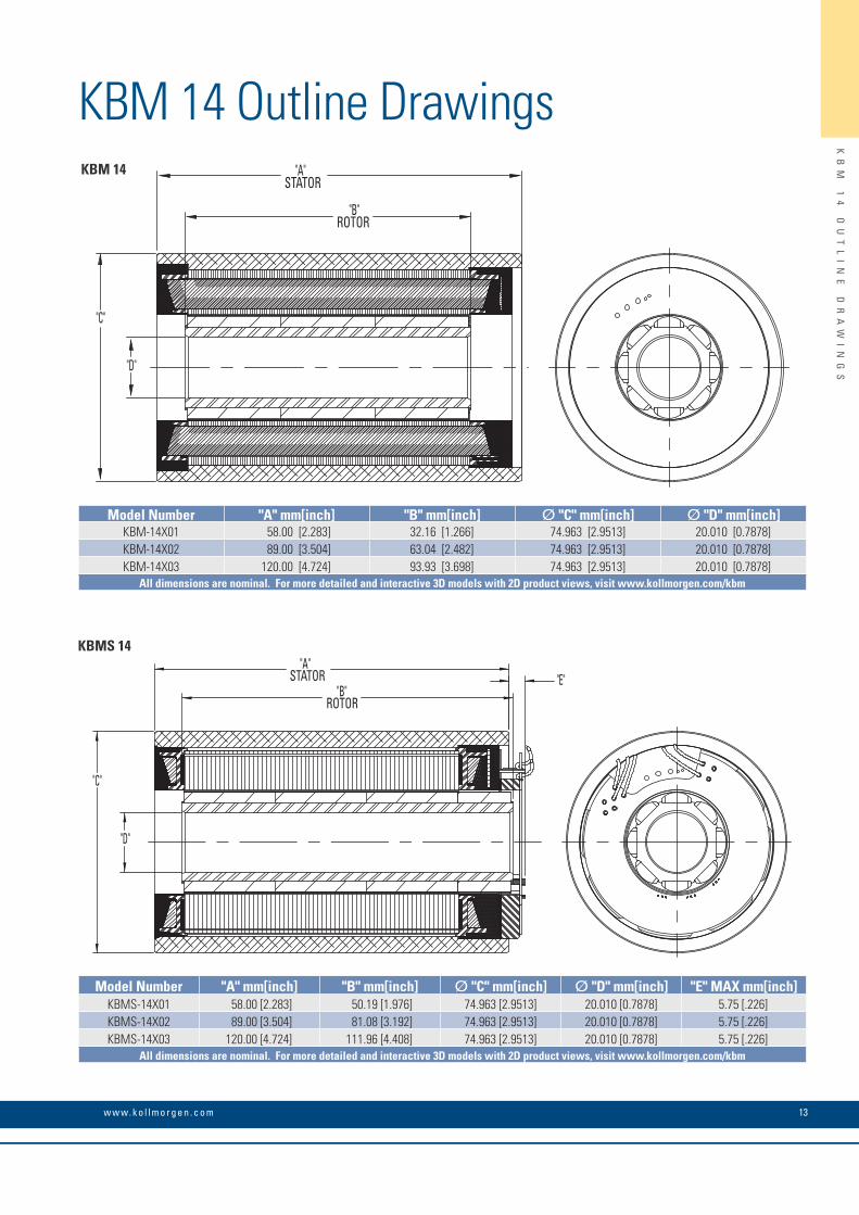
Model Number "A" mm[inch] "B" mm[inch] Ø "C" mm[inch] Ø "D" mm[inch]KBM-14X01 58.00 [2.283] 32.16 [1.266] 74.963 [2.9513] 20.010 [0.7878]KBM-14X02 89.00 [3.504] 63.04 [2.482] 74.963 [2.9513] 20.010 [0.7878]KBM-14X03 120.00 [4.724] 93.93 [3.698] 74.963 [2.9513] 20.010 [0.7878]
All dimensions are nominal. For more detailed and interactive 3D models with 2D product views, visit www.kollmorgen.com/kbm
Model Number "A" mm[inch] "B" mm[inch] Ø "C" mm[inch] Ø "D" mm[inch] "E" MAX mm[inch]KBMS-14X01 58.00 [2.283] 50.19 [1.976] 74.963 [2.9513] 20.010 [0.7878] 5.75 [.226]KBMS-14X02 89.00 [3.504] 81.08 [3.192] 74.963 [2.9513] 20.010 [0.7878] 5.75 [.226]KBMS-14X03 120.00 [4.724] 111.96 [4.408] 74.963 [2.9513] 20.010 [0.7878] 5.75 [.226]
All dimensions are nominal. For more detailed and interactive 3D models with 2D product views, visit www.kollmorgen.com/kbm
K O L L M O R G E N 14
KB
M
14
P
ER
FO
RM
AN
CE
C
UR
VE
S
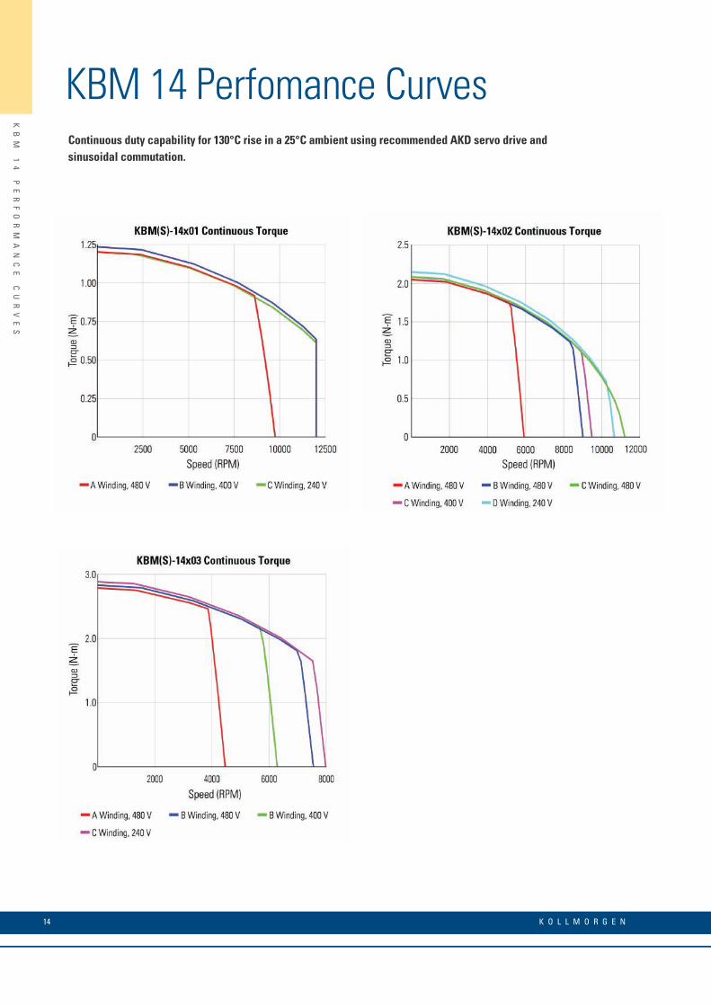
KBM 14 Perfomance CurvesContinuous duty capability for 130°C rise in a 25°C ambient using recommended AKD servo drive and sinusoidal commutation.
15w w w. k o l l m o r g e n . c o m
KB
M
14
P
ER
FO
RM
AN
CE
D
AT
A
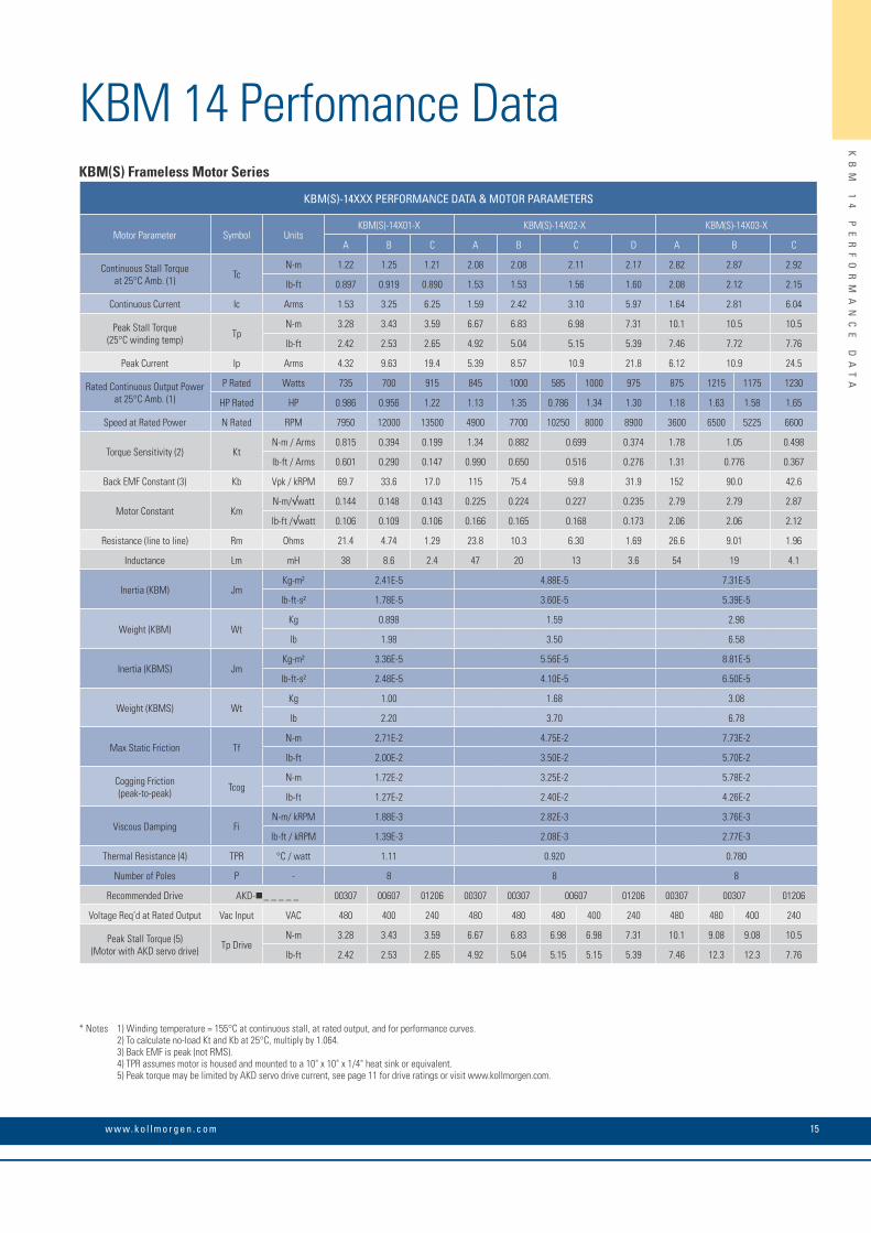
KBM 14 Perfomance DataKBM(S) Frameless Motor Series
KBM(S)-14XXX PERFORMANCE DATA & MOTOR PARAMETERS
Motor Parameter Symbol UnitsKBM(S)-14X01-X KBM(S)-14X02-X KBM(S)-14X03-X
A B C A B C D A B C
Continuous Stall Torque at 25°C Amb. (1) Tc
N-m 1.22 1.25 1.21 2.08 2.08 2.11 2.17 2.82 2.87 2.92
lb-ft 0.897 0.919 0.890 1.53 1.53 1.56 1.60 2.08 2.12 2.15
Continuous Current Ic Arms 1.53 3.25 6.25 1.59 2.42 3.10 5.97 1.64 2.81 6.04
Peak Stall Torque (25°C winding temp) Tp
N-m 3.28 3.43 3.59 6.67 6.83 6.98 7.31 10.1 10.5 10.5
lb-ft 2.42 2.53 2.65 4.92 5.04 5.15 5.39 7.46 7.72 7.76
Peak Current Ip Arms 4.32 9.63 19.4 5.39 8.57 10.9 21.8 6.12 10.9 24.5
Rated Continuous Output Power at 25°C Amb. (1)
P Rated Watts 735 700 915 845 1000 585 1000 975 875 1215 1175 1230
HP Rated HP 0.986 0.956 1.22 1.13 1.35 0.786 1.34 1.30 1.18 1.63 1.58 1.65
Speed at Rated Power N Rated RPM 7950 12000 13500 4900 7700 10250 8000 8900 3600 6500 5225 6600
Torque Sensitivity (2) KtN-m / Arms 0.815 0.394 0.199 1.34 0.882 0.699 0.374 1.78 1.05 0.498
lb-ft / Arms 0.601 0.290 0.147 0.990 0.650 0.516 0.276 1.31 0.776 0.367
Back EMF Constant (3) Kb Vpk / kRPM 69.7 33.6 17.0 115 75.4 59.8 31.9 152 90.0 42.6
Motor Constant KmN-m/√watt 0.144 0.148 0.143 0.225 0.224 0.227 0.235 2.79 2.79 2.87
lb-ft /√watt 0.106 0.109 0.106 0.166 0.165 0.168 0.173 2.06 2.06 2.12
Resistance (line to line) Rm Ohms 21.4 4.74 1.29 23.8 10.3 6.30 1.69 26.6 9.01 1.96
Inductance Lm mH 38 8.6 2.4 47 20 13 3.6 54 19 4.1
Inertia (KBM) JmKg-m² 2.41E-5 4.88E-5 7.31E-5
lb-ft-s² 1.78E-5 3.60E-5 5.39E-5
Weight (KBM) WtKg 0.898 1.59 2.98
lb 1.98 3.50 6.58
Inertia (KBMS) JmKg-m² 3.36E-5 5.56E-5 8.81E-5
lb-ft-s² 2.48E-5 4.10E-5 6.50E-5
Weight (KBMS) WtKg 1.00 1.68 3.08
lb 2.20 3.70 6.78
Max Static Friction TfN-m 2.71E-2 4.75E-2 7.73E-2
lb-ft 2.00E-2 3.50E-2 5.70E-2
Cogging Friction (peak-to-peak) Tcog
N-m 1.72E-2 3.25E-2 5.78E-2
lb-ft 1.27E-2 2.40E-2 4.26E-2
Viscous Damping FiN-m/ kRPM 1.88E-3 2.82E-3 3.76E-3
lb-ft / kRPM 1.39E-3 2.08E-3 2.77E-3
Thermal Resistance (4) TPR °C / watt 1.11 0.920 0.780
Number of Poles P - 8 8 8
Recommended Drive AKD- _ _ _ _ _ 00307 00607 01206 00307 00307 00607 01206 00307 00307 01206
Voltage Req’d at Rated Output Vac Input VAC 480 400 240 480 480 480 400 240 480 480 400 240
Peak Stall Torque (5) (Motor with AKD servo drive) Tp Drive
N-m 3.28 3.43 3.59 6.67 6.83 6.98 6.98 7.31 10.1 9.08 9.08 10.5
lb-ft 2.42 2.53 2.65 4.92 5.04 5.15 5.15 5.39 7.46 12.3 12.3 7.76
* Notes 1) Winding temperature = 155°C at continuous stall, at rated output, and for performance curves. 2) To calculate no-load Kt and Kb at 25°C, multiply by 1.064. 3) Back EMF is peak (not RMS). 4) TPR assumes motor is housed and mounted to a 10" x 10" x 1/4" heat sink or equivalent. 5) Peak torque may be limited by AKD servo drive current, see page 11 for drive ratings or visit www.kollmorgen.com.
K O L L M O R G E N 16
KB
M
17
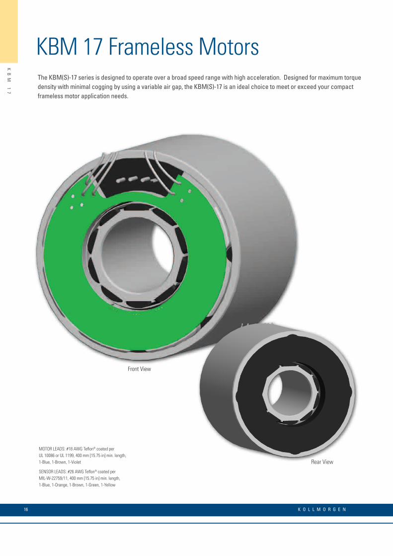
KBM 17 Frameless MotorsThe KBM(S)-17 series is designed to operate over a broad speed range with high acceleration. Designed for maximum torque density with minimal cogging by using a variable air gap, the KBM(S)-17 is an ideal choice to meet or exceed your compact frameless motor application needs.
MOTOR LEADS: #18 AWG Teflon® coated perUL 10086 or UL 1199, 400 mm [15.75 in] min. length,1-Blue, 1-Brown, 1-Violet
SENSOR LEADS: #26 AWG Teflon® coated perMIL-W-22759/11, 400 mm [15.75 in] min. length,1-Blue, 1-Orange, 1-Brown, 1-Green, 1-Yellow
Rear View
Front View
17w w w. k o l l m o r g e n . c o m
KB
M
17
O
UT
LI
NE
D
RA
WI
NG
S
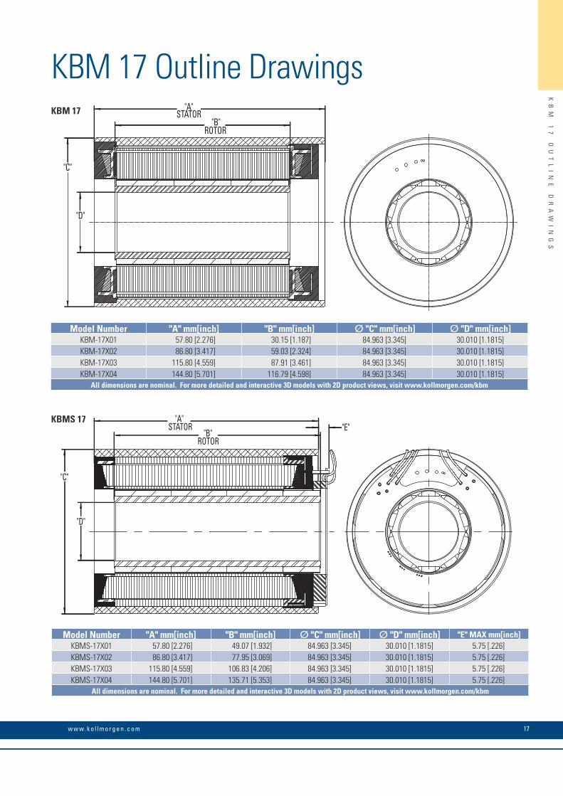
KBM 17 Outline Drawings "A"
STATOR "B"
ROTOR
"D"
"C"
KBM 17
"A"STATOR
"B"ROTOR
"D"
"C"
"E"KBMS 17
Model Number "A" mm[inch] "B" mm[inch] Ø "C" mm[inch] Ø "D" mm[inch]KBM-17X01 57.80 [2.276] 30.15 [1.187] 84.963 [3.345] 30.010 [1.1815]KBM-17X02 86.80 [3.417] 59.03 [2.324] 84.963 [3.345] 30.010 [1.1815]KBM-17X03 115.80 [4.559] 87.91 [3.461] 84.963 [3.345] 30.010 [1.1815]KBM-17X04 144.80 [5.701] 116.79 [4.598] 84.963 [3.345] 30.010 [1.1815]
All dimensions are nominal. For more detailed and interactive 3D models with 2D product views, visit www.kollmorgen.com/kbm
Model Number "A" mm[inch] "B" mm[inch] Ø "C" mm[inch] Ø "D" mm[inch] "E" MAX mm[inch]KBMS-17X01 57.80 [2.276] 49.07 [1.932] 84.963 [3.345] 30.010 [1.1815] 5.75 [.226]KBMS-17X02 86.80 [3.417] 77.95 [3.069] 84.963 [3.345] 30.010 [1.1815] 5.75 [.226]KBMS-17X03 115.80 [4.559] 106.83 [4.206] 84.963 [3.345] 30.010 [1.1815] 5.75 [.226]KBMS-17X04 144.80 [5.701] 135.71 [5.353] 84.963 [3.345] 30.010 [1.1815] 5.75 [.226]
All dimensions are nominal. For more detailed and interactive 3D models with 2D product views, visit www.kollmorgen.com/kbm
K O L L M O R G E N 18
KB
M
17
P
ER
FO
RM
AN
CE
C
UR
VE
S
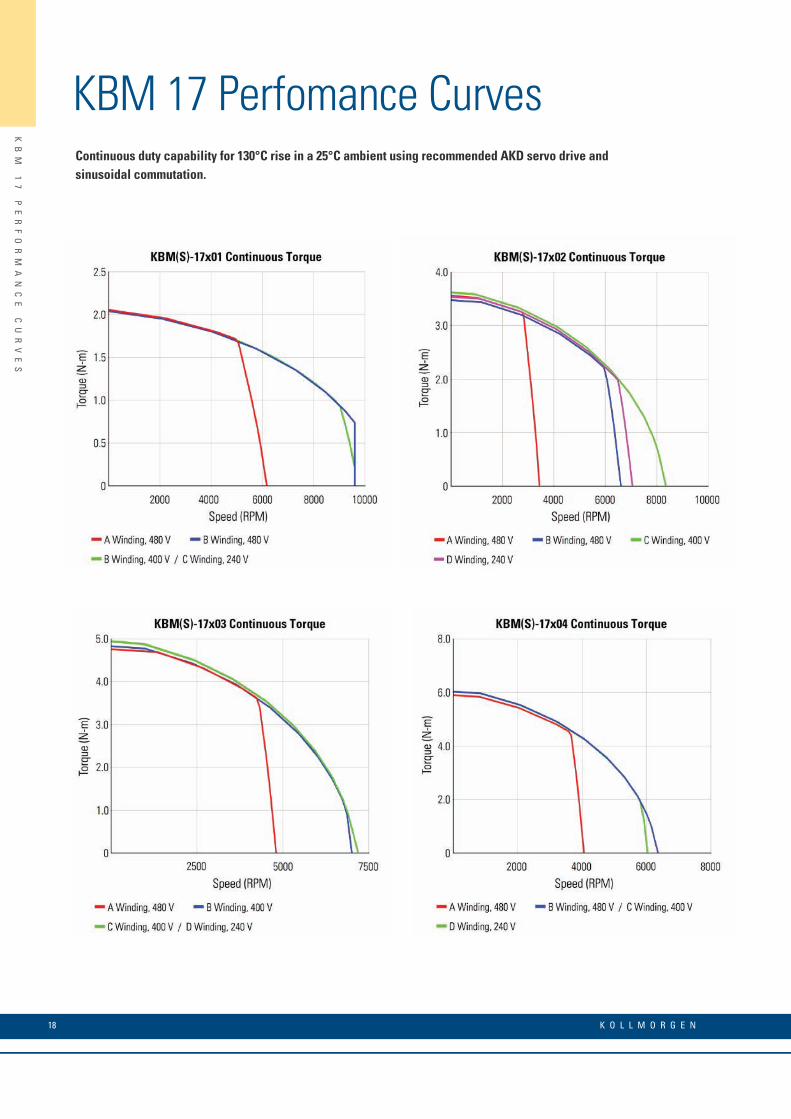
KBM 17 Perfomance CurvesContinuous duty capability for 130°C rise in a 25°C ambient using recommended AKD servo drive and sinusoidal commutation.
19w w w. k o l l m o r g e n . c o m
KB
M
17
P
ER
FO
RM
AN
CE
D
AT
A
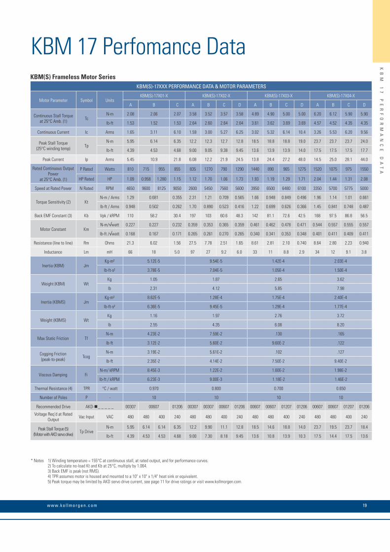
KBM 17 Perfomance Data
* Notes 1) Winding temperature = 155°C at continuous stall, at rated output, and for performance curves. 2) To calculate no-load Kt and Kb at 25°C, multiply by 1.064. 3) Back EMF is peak (not RMS). 4) TPR assumes motor is housed and mounted to a 10" x 10" x 1/4" heat sink or equivalent. 5) Peak torque may be limited by AKD servo drive current, see page 11 for drive ratings or visit www.kollmorgen.com.
KBM(S) Frameless Motor SeriesKBM(S)-17XXX PERFORMANCE DATA & MOTOR PARAMETERS
Motor Parameter Symbol UnitsKBM(S)-17X01-X KBM(S)-17X02-X KBM(S)-17X03-X KBM(S)-17X04-X
A B C A B C D A B C D A B C D
Continuous Stall Torque at 25°C Amb. (1) Tc
N-m 2.08 2.06 2.07 3.58 3.52 3.57 3.58 4.89 4.90 5.00 5.00 6.20 6.12 5.90 5.90
lb-ft 1.53 1.52 1.53 2.64 2.60 2.64 2.64 3.61 3.62 3.69 3.69 4.57 4.52 4.35 4.35
Continuous Current Ic Arms 1.65 3.11 6.10 1.59 3.00 5.27 6.25 3.02 5.32 6.14 10.4 3.26 5.53 6.20 9.56
Peak Stall Torque (25°C winding temp) Tp
N-m 5.95 6.14 6.35 12.2 12.3 12.7 12.8 18.5 18.8 18.8 19.0 23.7 23.7 23.7 24.0
lb-ft 4.39 4.53 4.68 9.00 9.05 9.38 9.45 13.6 13.9 13.9 14.0 17.5 17.5 17.5 17.7
Peak Current Ip Arms 5.45 10.9 21.8 6.08 12.2 21.9 24.5 13.8 24.4 27.2 48.0 14.5 25.0 28.1 44.0
Rated Continuous Output Power
at 25°C Amb. (1)
P Rated Watts 810 715 955 855 835 1270 790 1290 1440 890 965 1275 1520 1075 975 1550
HP Rated HP 1.09 0.958 1.280 1.15 1.12 1.70 1.06 1.73 1.93 1.19 1.29 1.71 2.04 1.44 1.31 2.08
Speed at Rated Power N Rated RPM 4650 9600 8125 9050 2600 5450 7560 5600 3950 6500 6480 6100 3350 5700 5775 5000
Torque Sensitivity (2) KtN-m / Arms 1.29 0.681 0.355 2.31 1.21 0.709 0.565 1.66 0.948 0.849 0.496 1.96 1.14 1.01 0.661
lb-ft / Arms 0.948 0.502 0.262 1.70 0.890 0.523 0.416 1.22 0.699 0.626 0.366 1.45 0.841 0.748 0.487
Back EMF Constant (3) Kb Vpk / kRPM 110 58.2 30.4 197 103 60.6 48.3 142 81.1 72.6 42.5 168 97.5 86.8 56.5
Motor Constant KmN-m/√watt 0.227 0.227 0.232 0.359 0.353 0.365 0.359 0.461 0.462 0.478 0.471 0.544 0.557 0.555 0.557
lb-ft /√watt 0.168 0.167 0.171 0.265 0.261 0.270 0.265 0.340 0.341 0.353 0.348 0.401 0.411 0.409 0.411
Resistance (line to line) Rm Ohms 21.3 6.02 1.56 27.5 7.78 2.51 1.65 8.61 2.81 2.10 0.740 8.64 2.80 2.23 0.940
Inductance Lm mH 66 18 5.0 97 27 9.2 6.0 33 11 8.8 2.9 34 12 9.1 3.8
Inertia (KBM) JmKg-m² 5.12E-5 9.54E-5 1.42E-4 2.03E-4
lb-ft-s² 3.78E-5 7.04E-5 1.05E-4 1.50E-4
Weight (KBM) WtKg 1.05 1.87 2.65 3.62
lb 2.31 4.12 5.85 7.98
Inertia (KBMS) JmKg-m² 8.62E-5 1.28E-4 1.75E-4 2.40E-4
lb-ft-s² 6.36E-5 9.45E-5 1.29E-4 1.77E-4
Weight (KBMS) WtKg 1.16 1.97 2.76 3.72
lb 2.55 4.35 6.08 8.20
Max Static Friction TfN-m 4.23E-2 7.59E-2 .130 .165
lb-ft 3.12E-2 5.60E-2 9.60E-2 .122
Cogging Friction (peak-to-peak) Tcog
N-m 3.19E-2 5.61E-2 .102 .127
lb-ft 2.35E-2 4.14E-2 7.50E-2 9.40E-2
Viscous Damping FiN-m/ kRPM 8.45E-3 1.22E-2 1.60E-2 1.98E-2
lb-ft / kRPM 6.23E-3 9.00E-3 1.18E-2 1.46E-2
Thermal Resistance (4) TPR °C / watt 0.970 0.800 0.700 0.650
Number of Poles P - 10 10 10 10
Recommended Drive AKD- _ _ _ _ _ 00307 00607 01206 00307 00307 00607 01206 00607 00607 01207 01206 00607 00607 01207 01206
Voltage Req’d at Rated Output Vac Input VAC 480 480 400 240 480 480 400 240 480 480 400 240 480 480 400 240
Peak Stall Torque (5) (Motor with AKD servo drive) Tp Drive
N-m 5.95 6.14 6.14 6.35 12.2 9.90 11.1 12.8 18.5 14.6 18.8 14.0 23.7 19.5 23.7 18.4
lb-ft 4.39 4.53 4.53 4.68 9.00 7.30 8.18 9.45 13.6 10.8 13.9 10.3 17.5 14.4 17.5 13.6

20 K O L L M O R G E N
KBM 25 Frameless MotorsThe KBM(S)-25 series is designed to operate over a broad speed range with high acceleration. Designed for maximum torque density with minimal cogging by using a variable air gap, the KBM(S)-25 is an ideal choice to meet or exceed your compact frameless motor application needs.
MOTOR LEADS: #14 AWG Teflon® coated perUL 10086 or UL 1199, 400 mm [15.75 in] min. length,1-Blue, 1-Brown, 1-Violet
SENSOR LEADS: #26 AWG Teflon® coated perMIL-W-22759/11, 400 mm [15.75 in] min. length,1-Blue, 1-Orange, 1-Brown, 1-Green, 1-Yellow
Rear View
Front View
KB
M
25
27w w w. k o l l m o r g e n . c o m
KB
M
25
O
UT
LI
NE
D
RA
WI
NG
S
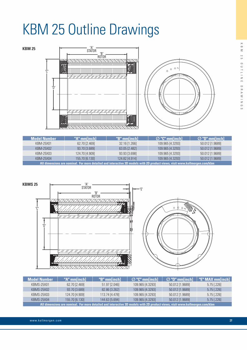
KBM 25 Outline Drawings
21
"A"STATOR
"B"ROTOR
"D"
"C"
"B"ROTOR
"A"STATOR "E"
"D"
"C"
KBM 25
KBMS 25
Model Number "A" mm[inch] "B" mm[inch] Ø "C" mm[inch] Ø "D" mm[inch]KBM-25X01 62.70 [2.469] 32.16 [1.266] 109.965 [4.3293] 50.012 [1.9689]KBM-25X02 93.70 [3.689] 63.05 [2.482] 109.965 [4.3293] 50.012 [1.9689]KBM-25X03 124.70 [4.909] 93.93 [3.698] 109.965 [4.3293] 50.012 [1.9689]KBM-25X04 155.70 [6.130] 124.82 [4.914] 109.965 [4.3293] 50.012 [1.9689]
All dimensions are nominal. For more detailed and interactive 3D models with 2D product views, visit www.kollmorgen.com/kbm
Model Number "A" mm[inch] "B" mm[inch] Ø "C" mm[inch] Ø "D" mm[inch] "E" MAX mm[inch]KBMS-25X01 62.70 [2.469] 51.97 [2.046] 109.965 [4.3293] 50.012 [1.9689] 5.75 [.226]KBMS-25X02 93.70 [3.689] 82.86 [3.262] 109.965 [4.3293] 50.012 [1.9689] 5.75 [.226]KBMS-25X03 124.70 [4.909] 113.74 [4.478] 109.965 [4.3293] 50.012 [1.9689] 5.75 [.226]KBMS-25X04 155.70 [6.130] 144.63 [5.694] 109.965 [4.3293] 50.012 [1.9689] 5.75 [.226]
All dimensions are nominal. For more detailed and interactive 3D models with 2D product views, visit www.kollmorgen.com/kbm
KOLLMORGEN
KB
M
25
P
ER
FO
RM
AN
CE
C
UR
VE
S
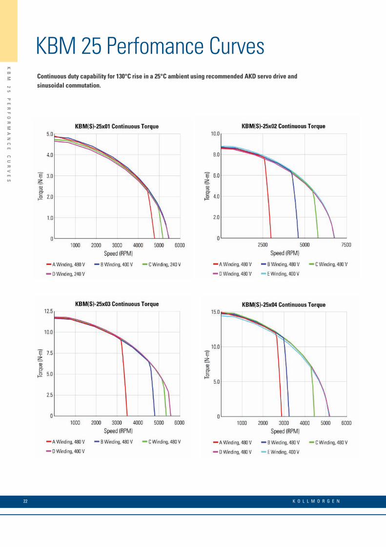
KBM 25 Perfomance CurvesContinuous duty capability for 130°C rise in a 25°C ambient using recommended AKD servo drive and sinusoidal commutation.
K O L L M O R G E N 22
21
KB
M
25
P
ER
FO
RM
AN
CE
D
AT
A
KBM 25 Perfomance Data
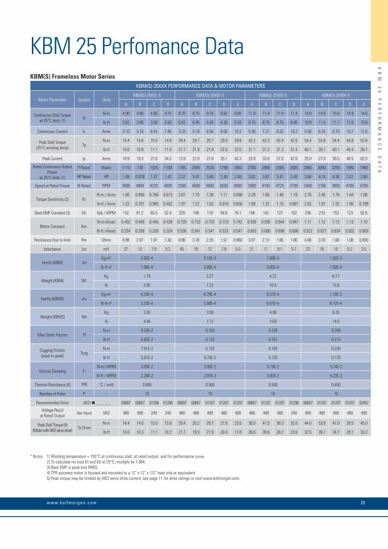
* Notes 1) Winding temperature = 155°C at continuous stall, at rated output, and for performance curve. 2) To calculate no-load Kt and Kb at 25°C, multiply by 1.064. 3) Back EMF is peak (not RMS). 4) TPR assumes motor is housed and mounted to a 12" x 12" x 1/2" heat sink or equivalent. 5) Peak torque may be limited by AKD servo drive current, see page 11 for drive ratings or visit www.kollmorgen.com.
KBM(S) Frameless Motor SeriesKBM(S)-25XXX PERFORMANCE DATA & MOTOR PARAMETERS
Motor Parameter Symbol UnitsKBM(S)-25X01-X KBM(S)-25X02-X KBM(S)-25X03-X KBM(S)-25X04-X
A B C D A B C D E A B C D A B C D E
Continuous Stall Torque at 25°C Amb. (1) Tc
N-m 4.90 4.96 4.85 4.75 8.70 8.75 8.75 8.62 8.85 11.9 11.9 11.9 11.9 14.8 14.9 15.0 14.9 14.6
lb-ft 3.62 3.66 3.58 3.50 6.42 6.45 6.45 6.36 6.53 8.75 8.75 8.75 8.80 10.9 11.0 11.1 11.0 10.8
Continuous Current Ic Arms 3.10 5.34 6.45 7.95 3.33 5.18 6.50 8.00 10.2 5.30 7.27 8.20 10.2 5.50 6.25 8.70 10.7 12.8
Peak Stall Torque (25°C winding temp) Tp
N-m 14.4 14.6 15.0 14.9 29.4 29.7 29.7 29.8 29.8 42.2 42.3 42.4 42.6 54.4 53.8 54.4 54.8 53.8
lb-ft 10.6 10.8 11.1 11.0 21.7 21.9 21.9 22.0 22.0 31.1 31.2 31.3 31.4 40.1 39.7 40.1 40.4 39.7
Peak Current Ip Arms 10.9 19.3 27.6 34.3 13.9 22.0 27.8 35.1 43.3 23.9 33.0 37.0 47.0 25.0 27.5 38.5 48.5 62.5
Rated Continuous Output Power
at 25°C Amb. (1)
P Rated Watts 1110 730 1025 1100 1765 2545 2535 1790 1850 2700 2890 2585 2605 2865 3090 3255 1990 1940
HP Rated HP 1.49 0.979 1.37 1.42 2.37 3.41 3.40 2.40 2.48 3.62 3.87 3.47 3.49 3.84 4.14 4.36 2.67 2.60
Speed at Rated Power N Rated RPM 3800 4900 4225 4000 2300 4000 5000 6000 6000 2900 4150 4725 2700 2400 2700 3850 4700 4700
Torque Sensitivity (2) KtN-m / Arms 1.66 0.950 0.766 0.613 2.67 1.73 1.38 1.11 0.890 2.29 1.66 1.49 1.19 2.76 2.46 1.79 1.44 1.08
lb-ft / Arms 1.22 0.701 0.565 0.452 1.97 1.27 1.02 0.818 0.656 1.69 1.22 1.10 0.881 2.03 1.81 1.32 1.06 0.799
Back EMF Constant (3) Kb Vpk / kRPM 142 81.2 65.5 52.4 229 148 118 94.8 76.1 196 142 127 102 236 210 153 123 92.6
Motor Constant KmN-m/√watt 0.452 0.458 0.445 0.439 0.729 0.733 0.733 0.723 0.742 0.939 0.936 0.944 0.947 1.11 1.12 1.13 1.13 1.10
lb-ft /√watt 0.334 0.338 0.328 0.324 0.538 0.541 0.541 0.533 0.547 0.693 0.690 0.696 0.698 0.822 0.827 0.834 0.832 0.809
Resistance (line to line) Rm Ohms 8.98 2.87 1.97 1.30 8.96 3.70 2.35 1.57 0.960 3.97 2.10 1.66 1.06 4.08 3.20 1.66 1.08 0.650
Inductance Lm mH 37 12 7.9 5.2 45 19 12 7.8 5.0 21 11 9.1 5.7 23 18 10 6.2 3.5
Inertia (KBM) JmKg-m² 2.66E-4 5.15E-4 7.66E-4 1.02E-3
lb-ft-s² 1.96E-4 3.80E-4 5.65E-4 7.50E-4
Weight (KBM) WtKg 1.79 3.27 4.72 6.17
lb 3.95 7.22 10.4 13.6
Inertia (KBMS) JmKg-m² 4.34E-4 6.78E-4 9.31E-4 1.18E-3
lb-ft-s² 3.20E-4 5.00E-4 6.87E-4 8.72E-4
Weight (KBMS) WtKg 2.02 3.50 4.90 6.35
lb 4.45 7.72 10.8 14.0
Max Static Friction TfN-m 9.25E-2 0.163 0.226 0.289
lb-ft 6.82E-2 0.120 0.167 0.213
Cogging Friction (peak-to-peak) Tcog
N-m 7.61E-2 0.132 0.183 0.230
lb-ft 5.61E-2 9.70E-2 0.135 0.170
Viscous Damping FiN-m/ kRPM 3.09E-2 3.95E-2 5.19E-2 5.74E-2
lb-ft / kRPM 2.28E-2 2.91E-2 3.83E-2 4.23E-2
Thermal Resistance (4) TPR °C / watt 0.680 0.560 0.500 0.450
Number of Poles P - 10 10 10 10
Recommended Drive AKD-_ _ _ _ _ 00607 00607 01206 01206 00607 00607 01207 01207 01207 00607 01207 01207 01206 00607 01207 01207 01207 02407
Voltage Req’d at Rated Output Vac Input VAC 480 400 240 240 480 480 480 480 400 480 480 480 240 480 480 480 480 400
Peak Stall Torque (5) (Motor with AKD servo drive) Tp Drive
N-m 14.4 14.0 15.0 13.8 29.4 26.2 29.7 27.6 23.0 36.0 41.5 38.3 32.0 44.0 53.8 47.0 39.5 45.0
lb-ft 10.6 10.3 11.1 10.2 21.7 19.3 21.9 20.4 17.0 26.6 30.6 28.2 23.6 32.5 39.7 34.7 29.1 33.2
23w w w. k o l l m o r g e n . c o m
KB
M
35
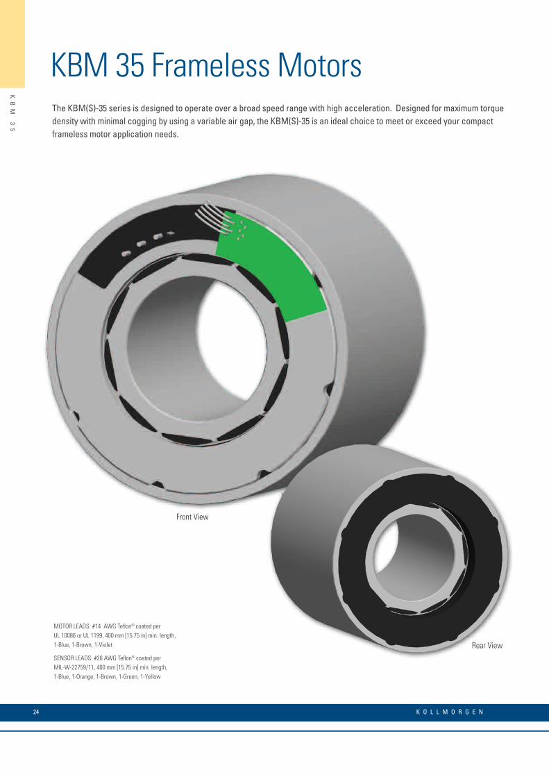
KBM 35 Frameless MotorsThe KBM(S)-35 series is designed to operate over a broad speed range with high acceleration. Designed for maximum torque density with minimal cogging by using a variable air gap, the KBM(S)-35 is an ideal choice to meet or exceed your compact frameless motor application needs.
MOTOR LEADS: #14 AWG Teflon® coated perUL 10086 or UL 1199, 400 mm [15.75 in] min. length,1-Blue, 1-Brown, 1-Violet
SENSOR LEADS: #26 AWG Teflon® coated perMIL-W-22759/11, 400 mm [15.75 in] min. length,1-Blue, 1-Orange, 1-Brown, 1-Green, 1-Yellow
Rear View
Front View
24 K O L L M O R G E N
KBM 35 Outline Drawings
KB
M
35
O
UT
LI
NE
D
RA
WI
NG
S
Rear View
"A"STATOR
"B"ROTOR
"D"
"C"
"A"STATOR
"B"ROTOR
"D"
"C"
"E"
KBM 35
KBMS 35
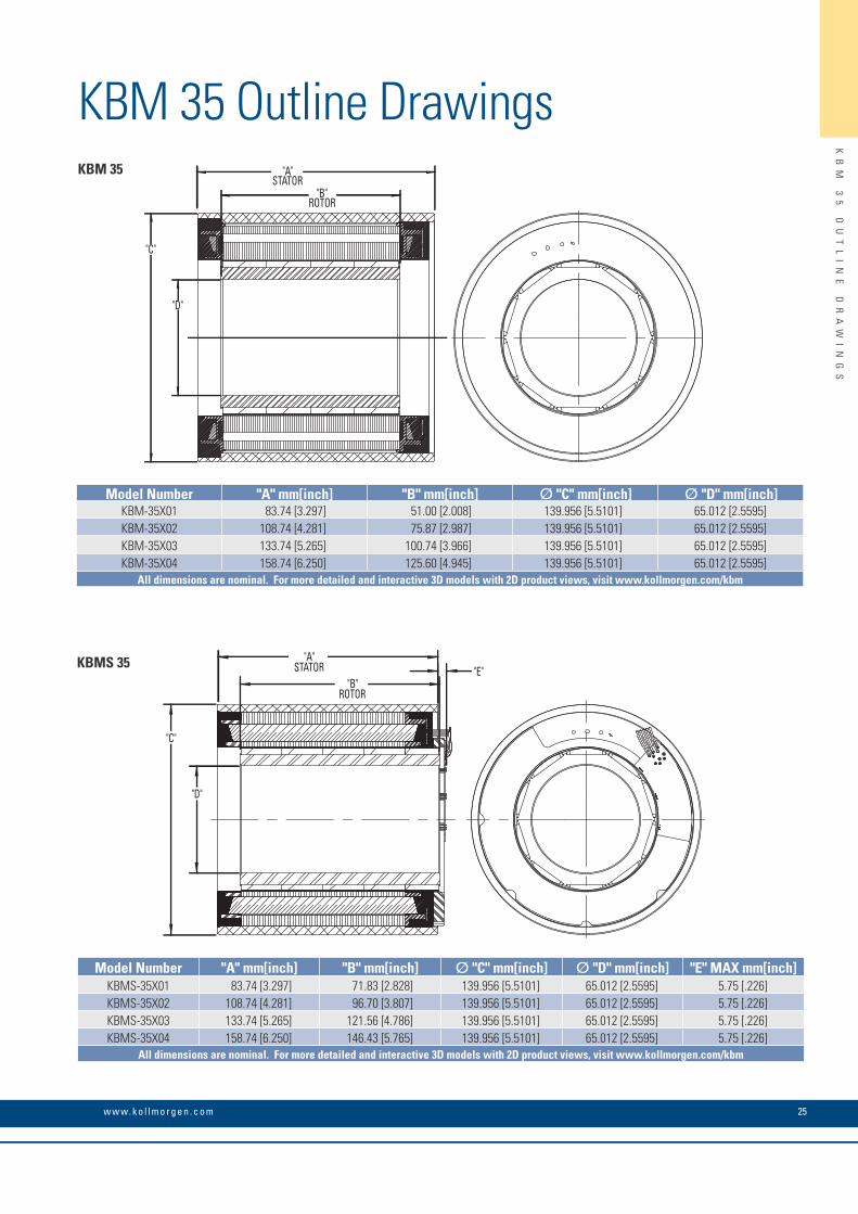
Model Number "A" mm[inch] "B" mm[inch] Ø "C" mm[inch] Ø "D" mm[inch]KBM-35X01 83.74 [3.297] 51.00 [2.008] 139.956 [5.5101] 65.012 [2.5595]KBM-35X02 108.74 [4.281] 75.87 [2.987] 139.956 [5.5101] 65.012 [2.5595]KBM-35X03 133.74 [5.265] 100.74 [3.966] 139.956 [5.5101] 65.012 [2.5595]KBM-35X04 158.74 [6.250] 125.60 [4.945] 139.956 [5.5101] 65.012 [2.5595]
All dimensions are nominal. For more detailed and interactive 3D models with 2D product views, visit www.kollmorgen.com/kbm
Model Number "A" mm[inch] "B" mm[inch] Ø "C" mm[inch] Ø "D" mm[inch] "E" MAX mm[inch]KBMS-35X01 83.74 [3.297] 71.83 [2.828] 139.956 [5.5101] 65.012 [2.5595] 5.75 [.226]KBMS-35X02 108.74 [4.281] 96.70 [3.807] 139.956 [5.5101] 65.012 [2.5595] 5.75 [.226]KBMS-35X03 133.74 [5.265] 121.56 [4.786] 139.956 [5.5101] 65.012 [2.5595] 5.75 [.226]KBMS-35X04 158.74 [6.250] 146.43 [5.765] 139.956 [5.5101] 65.012 [2.5595] 5.75 [.226]
All dimensions are nominal. For more detailed and interactive 3D models with 2D product views, visit www.kollmorgen.com/kbm
2125w w w. k o l l m o r g e n . c o m
26 K O L L M O R G E N
KB
M
35
P
ER
FO
RM
AN
CE
C
UR
VE
S
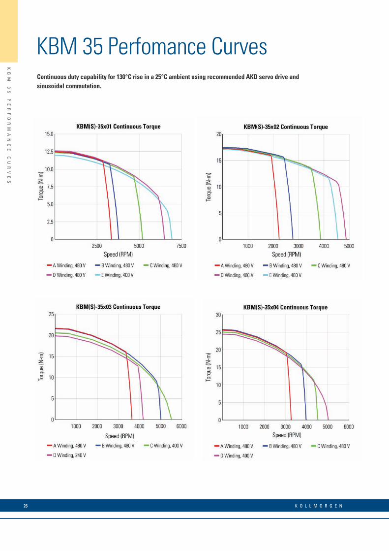
KBM 35 Perfomance CurvesContinuous duty capability for 130°C rise in a 25°C ambient using recommended AKD servo drive and sinusoidal commutation.

w w w. k o l l m o r g e n . c o m
KBM 35 Perfomance Data
KB
M
35
P
ER
FO
RM
AN
CE
D
AT
A
KBM(S) Frameless Motor Series KBM(S)-35XXX PERFORMANCE DATA & MOTOR PARAMETERS
Motor Parameter Symbol UnitsKBM(S)-35X01-X KBM(S)-35X02-X KBM(S)-35X03-X KBM(S)-35X04-X
A B C D E A B C D E A B C D A B C D
Continuous Stall Torque at 25°C Amb. (1) Tc
N-m 12.6 12.7 12.4 12.7 12.2 17.3 17.6 17.5 17.5 17.1 21.8 21.7 20.7 20.0 25.6 25.9 25.3 24.7
lb-ft 9.26 9.34 9.15 9.34 9.00 12.8 13.0 12.9 12.9 12.6 16.1 16.0 15.3 14.8 18.9 19.1 18.7 18.2
Continuous Current Ic Arms 5.41 6.10 8.32 10.6 12.9 4.97 6.30 8.70 10.9 12.1 10.2 14.0 20.2 21.5 10.9 13.3 14.7 19.2
Peak Stall Torque (25°C winding temp) Tp
N-m 40.9 40.8 41.1 41.2 41.1 58.8 58.8 59.2 59.4 59.4 76.1 76.6 75.2 75.7 92.3 93.0 93.0 91.5
lb-ft 30.1 30.1 30.3 30.4 30.3 43.4 43.4 43.7 43.8 43.8 56.1 56.5 55.5 55.8 68.1 68.6 68.6 67.5
Peak Current Ip Arms 21.9 24.5 34.7 43.5 55.4 22.5 28.0 39.2 49.5 55.4 46.1 64.0 93.1 104 49.0 61.0 68.0 89.0
Rated Continuous Output Power at 25°C Amb. (1)
P Rated Watts 2970 3100 3885 3750 3200 2750 3415 4395 4750 4610 5025 5160 2985 4735 5400 5750 4870 4500
HP Rated HP 3.98 4.16 5.21 5.03 4.29 3.69 4.58 5.89 6.37 6.18 6.74 6.92 4.00 6.35 7.24 7.71 6.53 6.03
Speed at Rated Power N Rated RPM 2700 2900 4200 5800 6125 1750 2200 3200 4300 3765 3100 4800 5000 3400 2800 3400 4150 4250
Torque Sensitivity (2) KtN-m /Arms 2.37 2.11 1.53 1.23 0.956 3.55 2.87 2.05 1.64 1.46 2.19 1.59 1.05 .956 2.44 2.01 1.76 1.32
lb-ft /Arms 1.75 1.55 1.13 0.904 0.705 2.62 2.12 1.51 1.21 1.08 1.62 1.17 0.776 0.705 1.80 1.48 1.30 0.975
Back EMF Constant (3) Kb Vpk / kRPM 203 180 131 105 81.8 304 246 175 140 125 187 136 90.0 81.8 208 172 151 113
Motor Constant KmN-m/√watt 0.954 0.947 0.946 0.963 0.908 1.24 1.27 1.25 1.25 1.23 1.51 1.50 1.43 1.38 1.71 1.73 1.68 1.65
lb-ft /√watt 0.704 0.699 0.698 0.710 0.670 0.912 0.934 0.921 0.923 0.908 1.11 1.11 1.06 1.02 1.26 1.28 1.24 1.21
Resistance (line to line) Rm Ohms 4.13 3.30 1.75 1.08 0.740 5.50 3.43 1.80 1.14 0.940 1.41 0.750 0.360 0.320 1.35 0.900 0.730 0.430
Inductance Lm mH 32 25 13 8.5 5.4 44 28 15 9.3 7.4 12 6.2 2.8 2.3 11 7.6 6.1 3.4
Inertia (KBM) JmKg-m² 1.52E-3 2.28E-3 3.04E-3 3.81E-3
lb-ft-s² 1.12E-3 1.68E-3 2.24E-3 2.81E-3
Weight (KBM) WtKg 4.68 6.76 8.80 10.9
lb 10.3 14.9 19.4 24.0
Inertia (KBMS) JmKg-m² 2.17E-3 2.94E-3 3.70E-3 4.46E-3
lb-ft-s² 1.60E-3 2.17E-3 2.73E-3 3.29E-3
Weight (KBMS) WtKg 5.17 7.21 9.34 11.3
lb 11.4 15.9 20.6 25.0
Max Static Friction TfN-m 0.247 0.346 0.450 0.598
lb-ft 0.182 0.255 0.332 0.441
Cogging Friction (peak-to-peak) Tcog
N-m 0.197 0.271 0.338 0.399
lb-ft 0.145 0.200 0.249 0.294
Viscous Damping FiN-m/ kRPM 3.76E-2 5.99E-2 7.51E-2 9.40E-2
lb-ft /kRPM 2.77E-2 4.42E-2 5.54E-2 6.93E-2
Thermal Resistance (4) TPR °C / watt 0.460 0.410 0.380 0.350
Number of Poles P - 10 10 10 10
Recommended Drive AKD- _ _ _ _ _ 00607 01207 01207 01207 02407 00607 01207 01207 01207 02407 01207 02407 02407 02406 01207 02407 02407 02407
Voltage Req’d at Rated Output Vac Input VAC 480 480 480 480 400 480 480 480 480 400 480 480 400 240 480 480 480 400
Peak Stall Torque (5) (Motor with AKD servo drive) Tp Drive
N-m 37.5 40.8 40.9 34.1 36.3 57.4 58.8 56.0 46.0 55.0 61.6 70.0 49.0 45.0 71.0 87.5 79.0 61.0
lb-ft 27.7 30.1 30.2 25.1 26.8 42.3 43.4 41.3 33.9 40.6 45.4 51.6 36.1 33.2 52.4 64.5 58.3 45.0
* Notes 1) Winding temperature = 155°C at continuous stall, at rated output, and for performance curves. 2) To calculate no-load Kt and Kb at 25°C, multiply by 1.064. 3) Back EMF is peak (not RMS). 4) TPR assumes motor is housed and mounted to a 18" x 18" x 1/2" heat sink or equivalent. 5) Peak torque may be limited by AKD servo drive current, see page 11 for drive ratings or visit www.kollmorgen.com.
27

28 K O L L M O R G E N
KB
M
43
KBM 43 Frameless MotorsThe KBM(S)-43 series provides a classic torque motor footprint - large diameter with a short axial length. With a skewed stator, low cogging, and low harmonic distortion these motors produce extremely smooth rotation. In addition, the high pole count and excellent torque / volume ratio makes the KBM(S)-43 an ideal fit for direct drive applications requiring high torque at low to moderate speeds.
MOTOR LEADS: #16 AWG Teflon® coated per UL 1199, 400 mm [15.75 in] min. length,1-Blue, 1-Brown, 1-Violet
SENSOR LEADS: #26 AWG Teflon® coated per MIL-W-22759/11, 400 mm [15.75 in] min. length,1-Blue, 1-Orange, 1-Brown, 1-Green, 1-Yellow
Rear View
Front ViewS
70
0
SE
RV
OV
ER
ST
ÄR
KE
R
w w w. k o l l m o r g e n . c o m
KBM 43 Outline Drawings
"C"
"D"
"F" "E""A"
"B"
"C"
"D"
"F" "E""A"KBMS 43
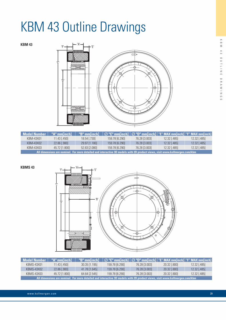
Model Number "A" mm[inch] "B" mm[inch] Ø "C" mm[inch] Ø "D" mm[inch] “E” MAX mm[inch] “F” MAX mm[inch]KBM-43X01 11.43 [.450] 18.54 [.730] 159.78 [6.290] 76.28 [3.003] 12.32 [.485] 12.32 [.485]KBM-43X02 22.86 [.900] 29.97 [1.180] 159.78 [6.290] 76.28 [3.003] 12.32 [.485] 12.32 [.485]KBM-43X03 45.72 [1.800] 52.83 [2.080] 159.78 [6.290] 76.28 [3.003] 12.32 [.485] 12.32 [.485]
All dimensions are nominal. For more detailed and interactive 3D models with 2D product views, visit www.kollmorgen.com/kbm
Model Number "A" mm[inch] "B" mm[inch] Ø "C" mm[inch] Ø "D" mm[inch] “E” MAX mm[inch] “F” MAX mm[inch]KBMS-43X01 11.43 [.450] 30.35 [1.195] 159.78 [6.290] 76.28 [3.003] 20.32 [.800] 12.32 [.485]KBMS-43X02 22.86 [.900] 41.78 [1.645] 159.78 [6.290] 76.28 [3.003] 20.32 [.800] 12.32 [.485]KBMS-43X03 45.72 [1.800] 64.64 [2.545] 159.78 [6.290] 76.28 [3.003] 20.32 [.800] 12.32 [.485]
All dimensions are nominal. For more detailed and interactive 3D models with 2D product views, visit www.kollmorgen.com/kbm
KBM 43
KB
M
43
O
UT
LI
NE
D
RA
WI
NG
S
29
30 K O L L M O R G E N
KB
M
43
P
ER
FO
RM
AN
CE
C
UR
VE
S
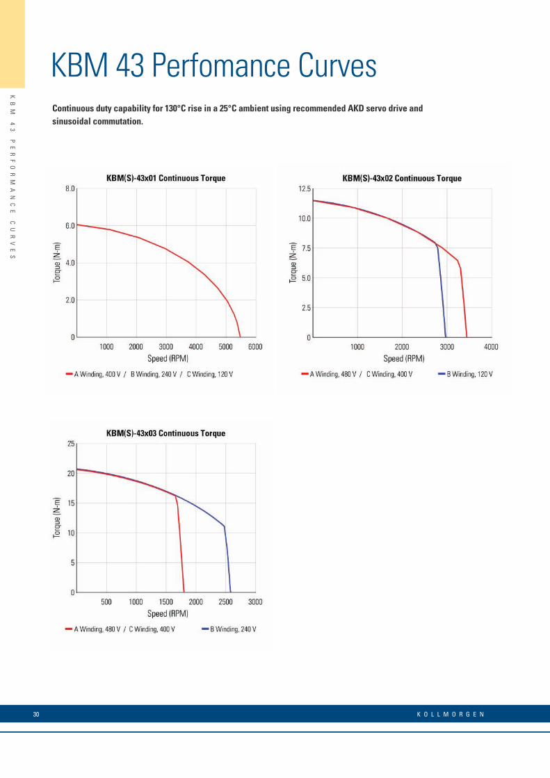
KBM 43 Perfomance CurvesContinuous duty capability for 130°C rise in a 25°C ambient using recommended AKD servo drive and sinusoidal commutation.

31w w w. k o l l m o r g e n . c o m
KB
M
43
P
ER
FO
RM
AN
CE
D
AT
A
KBM 43 Perfomance Data
* Notes 1) Winding temperature = 155°C at continuous stall, at rated output, and for performance curves. 2) To calculate no-load Kt and Kb at 25°C, multiply by 1.064. 3) Back EMF is peak (not RMS). 4) TPR assumes motor is housed and mounted to a 12" x 12" x 3/4" heat sink or equivalent. 5) Peak torque may be limited by AKD servo drive current, see page 11 for drive ratings or visit www.kollmorgen.com.
KBM(S) Frameless Motor SeriesKBM(S)-43XXX PERFORMANCE DATA & MOTOR PARAMETERS
Motor Parameter Symbol UnitsKBM(S)-43X01-X KBM(S)-43X02-X KBM(S)-43X03-X
A B C A B C D A B C D
Continuous Stall Torque at 25°C Amb. (1) Tc
N-m 6.11 6.24 6.11 11.6 11.6 11.9 11.9 21.0 20.7 20.9 20.9
lb-ft 4.51 4.60 4.51 8.57 8.53 8.57 8.57 15.5 15.3 15.4 15.4
Continuous Current Ic Arms 5.10 8.60 18.4 5.10 18.3 6.10 10.2 4.78 13.8 5.73 19.2
Peak Stall Torque (25°C winding temp) Tp
N-m 18.0 18.0 18.0 34.6 34.6 34.6 34.6 64.5 64.5 64.5 64.5
lb-ft 13.3 13.3 13.3 25.5 25.5 25.5 25.5 47.6 47.6 47.6 47.6
Peak Current Ip Arms 18.0 32.2 64.6 18.0 64.6 22.8 36.2 18.0 51.2 22.8 72.5
Rated Continuous Output Power
at 25°C Amb. (1)
P Rated Watts 1230 1230 1230 2160 2160 2160 2160 2520 2875 2520 2520
HP Rated HP 1.65 1.65 1.65 2.90 2.90 2.90 2.90 3.38 3.85 3.38 3.38
Speed at Rated Power N Rated RPM 4750 4750 4750 3000 2650 3000 3000 1500 2275 1500 1500
Torque Sensitivity (2) KtN-m / Arms 1.21 0.721 0.335 2.31 0.641 1.92 1.15 4.43 1.54 3.69 1.11
lb-ft / Arms 0.890 0.531 0.247 1.70 0.473 1.42 0.851 3.27 1.14 2.73 0.818
Back EMF Constant (3) Kb Vpk / kRPM 103 61.6 28.7 197 54.8 164 98.7 379 132 316 94.8
Motor Constant KmN-m/√watt 0.580 0.596 0.580 1.00 1.00 1.00 1.00 1.65 1.63 1.69 1.65
lb-ft /√watt 0.427 0.440 0.425 0.737 0.737 0.737 0.737 1.21 1.20 1.24 1.21
Resistance (line to line) Rm Ohms 2.90 0.976 0.226 3.55 0.277 2.35 0.886 4.83 0.595 3.20 0.301
Inductance Lm mH 6.8 2.4 0.52 12 0.93 8.3 3.0 19 2.2 13.0 1.2
Inertia (KBM) JmKg-m² 1.94E-3 2.85E-3 4.75E-3
lb-ft-s² 1.43E-3 2.10E-3 3.50E-3
Weight (KBM) WtKg 2.26 3.49 5.96
lb 4.98 7.70 13.1
Inertia (KBMS) JmKg-m² 2.85E-3 3.73E-3 5.69E-3
lb-ft-s² 2.10E-3 2.75E-3 4.20E-3
Weight (KBMS) WtKg 2.66 3.89 6.35
lb 5.86 8.57 14.0
Max Static Friction TfN-m 0.058 0.108 0.203
lb-ft 0.043 0.080 0.150
Cogging Friction (peak-to-peak) Tcog
N-m 0.027 0.054 0.102
lb-ft 0.020 0.040 0.075
Viscous Damping FiN-m/ kRPM 0.388 0.561 0.860
lb-ft / kRPM 0.286 0.414 1.17
Thermal Resistance (4) TPR °C / watt 0.763 0.629 0.525
Number of Poles P - 16 16 16
Recommended Drive AKD- _ _ _ _ _ 00607 01206 02406 00607 02406 01207 01206 00607 02406 00607 02406
Voltage Req’d at Rated Output Vac Input VAC 400 240 120 480 120 400 240 480 240 400 120
Peak Stall Torque (5) (Motor with AKD servo drive) Tp Drive
N-m 18.0 16.9 14.5 34.6 28.5 34.6 29.0 64.5 60.5 53.0 50
lb-ft 13.3 12.5 10.7 25.5 21.0 25.5 21.4 47.6 44.6 39.1 36.9
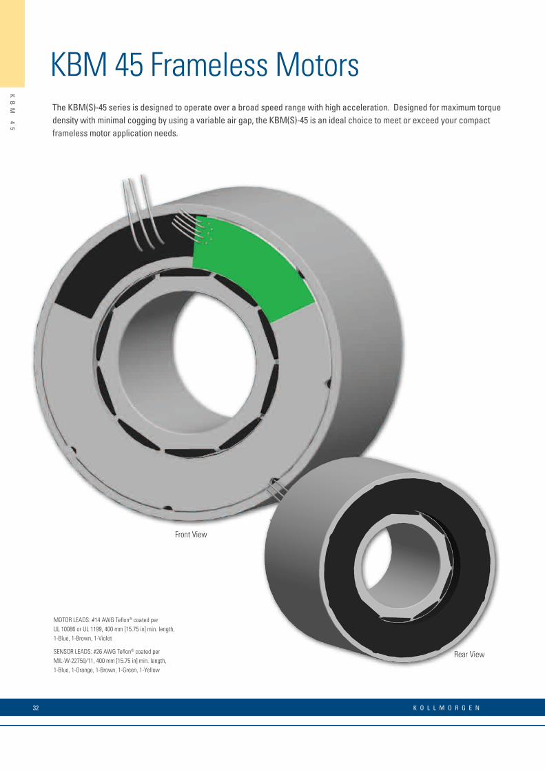
KBM 45 Frameless MotorsThe KBM(S)-45 series is designed to operate over a broad speed range with high acceleration. Designed for maximum torque density with minimal cogging by using a variable air gap, the KBM(S)-45 is an ideal choice to meet or exceed your compact frameless motor application needs.
MOTOR LEADS: #14 AWG Teflon® coated perUL 10086 or UL 1199, 400 mm [15.75 in] min. length,1-Blue, 1-Brown, 1-Violet
SENSOR LEADS: #26 AWG Teflon® coated perMIL-W-22759/11, 400 mm [15.75 in] min. length,1-Blue, 1-Orange, 1-Brown, 1-Green, 1-Yellow
Rear View
Front ViewK
BM
4
5
32 K O L L M O R G E N
KBM 45 Outline Drawings
KB
M
45
O
UT
LI
NE
D
RA
WI
NG
S
"A"STATOR
"B"ROTOR
"D"
"C"
KBM 45
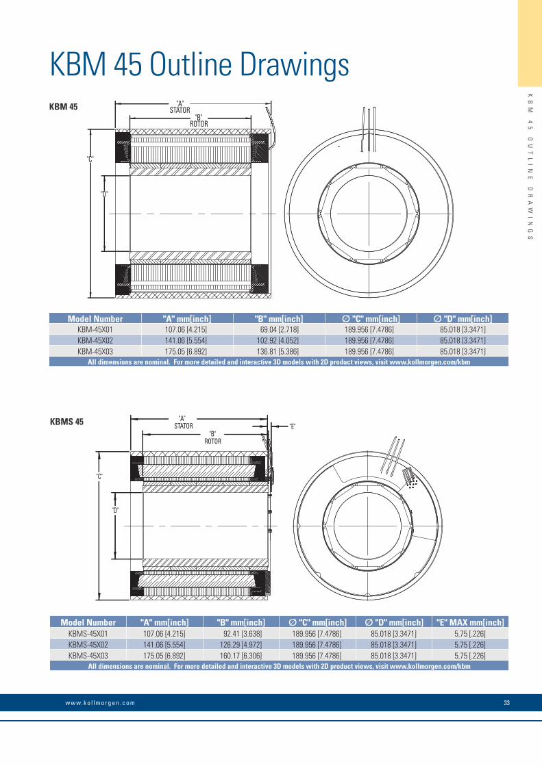
Model Number "A" mm[inch] "B" mm[inch] Ø "C" mm[inch] Ø "D" mm[inch]KBM-45X01 107.06 [4.215] 69.04 [2.718] 189.956 [7.4786] 85.018 [3.3471]KBM-45X02 141.06 [5.554] 102.92 [4.052] 189.956 [7.4786] 85.018 [3.3471]KBM-45X03 175.05 [6.892] 136.81 [5.386] 189.956 [7.4786] 85.018 [3.3471]
All dimensions are nominal. For more detailed and interactive 3D models with 2D product views, visit www.kollmorgen.com/kbm
"A"STATOR
"B"ROTOR
"E"
"D"
"C"
KBMS 45
Model Number "A" mm[inch] "B" mm[inch] Ø "C" mm[inch] Ø "D" mm[inch] "E" MAX mm[inch]KBMS-45X01 107.06 [4.215] 92.41 [3.638] 189.956 [7.4786] 85.018 [3.3471] 5.75 [.226]KBMS-45X02 141.06 [5.554] 126.29 [4.972] 189.956 [7.4786] 85.018 [3.3471] 5.75 [.226]KBMS-45X03 175.05 [6.892] 160.17 [6.306] 189.956 [7.4786] 85.018 [3.3471] 5.75 [.226]
All dimensions are nominal. For more detailed and interactive 3D models with 2D product views, visit www.kollmorgen.com/kbm
33w w w. k o l l m o r g e n . c o m

34 K O L L M O R G E N
KB
M
45
P
ER
FO
RM
AN
CE
C
UR
VE
S
KBM 45 Perfomance CurvesContinuous duty capability for 130°C rise in a 25°C ambient using recommended AKD servo drive and sinusoidal commutation.

35w w w. k o l l m o r g e n . c o m
KB
M
45
P
ER
FO
RM
AN
CE
D
AT
A
KBM 45 Perfomance Data
* Notes 1) Winding temperature = 155°C at continuous stall, at rated output, and for performance curves. 2) To calculate no-load Kt and Kb at 25°C, multiply by 1.064. 3) Back EMF is peak (not RMS). 4) TPR assumes motor is housed and mounted to a 18" x 18" x 1/2" heat sink or equivalent. 5) Peak torque may be limited by AKD servo drive current, see page 11 for drive ratings or visit www.kollmorgen.com.
KBM(S) Frameless Motor SeriesKBM(S)-45XXX PERFORMANCE DATA & MOTOR PARAMETERS
Motor Parameter Symbol UnitsKBM(S)-45X01-X KBM(S)-45X02-X KBM(S)-45X03-X
A B C D A B C A B
Continuous Stall Torque at 25°C Amb. (1) Tc
N-m 30.7 30.2 31.3 29.7 43.7 43.5 41.9 54.6 53.0
lb-ft 22.6 22.3 23.1 21.9 32.3 32.1 30.9 40.3 39.1
Continuous Current Ic Arms 10.2 12.5 14.3 20.2 13.3 14.9 21.1 14.1 19.9
Peak Stall Torque (25°C winding temp) Tp
N-m 119 119 119 118 170 171 168 218 215
lb-ft 87.6 87.6 88.0 86.7 126 126 124 161 159
Peak Current Ip Arms 46.5 57.5 65.0 93.5 60.5 68.0 97.2 64.5 92.5
Rated Continuous Output Power at 25°C Amb. (1)
P Rated Watts 5200 5750 6045 4930 6655 7200 4525 6500 7270 7580 7670
HP Rated HP 6.97 7.71 8.10 6.61 8.92 9.65 6.07 8.71 9.75 10.2 10.3
Speed at Rated Power N Rated RPM 2100 2650 3100 3700 1950 2350 3500 2830 1700 2600 2050
Torque Sensitivity (2) KtN-m / Arms 3.08 2.48 2.24 1.51 3.35 2.98 2.03 3.96 2.72
lb-ft / Arms 2.27 1.83 1.65 1.12 2.47 2.20 1.50 2.92 2.01
Back EMF Constant (3) Kb Vpk / kRPM 264 212 191 129 286 255 174 339 233
Motor Constant KmN-m/√watt 2.16 2.11 2.20 2.09 2.80 2.79 2.69 3.36 3.24
lb-ft /√watt 1.59 1.56 1.62 1.54 2.07 2.06 1.99 2.48 2.39
Resistance (line to line) Rm Ohms 1.36 0.920 0.690 0.350 0.950 0.760 0.380 0.930 0.470
Inductance Lm mH 21 14 11 5.0 16 12 5.9 16 7.7
Inertia (KBM) JmKg-m² 6.10E-3 9.22E-3 1.22E-2
lb-ft-s² 4.50E-3 6.80E-3 9.00E-3
Weight (KBM) WtKg 12.2 17.5 23.1
lb 26.9 38.6 51.0
Inertia (KBMS) JmKg-m² 8.35E-3 1.15E-2 1.45E-2
lb-ft-s² 6.16E-3 8.47E-3 1.07E-2
Weight (KBMS) WtKg 13.2 18.5 24.2
lb 29.0 40.7 53.3
Max Static Friction TfN-m 0.750 0.850 1.09
lb-ft 0.553 0.627 0.806
Cogging Friction (peak-to-peak) Tcog
N-m 0.630 0.671 0.846
lb-ft 0.465 0.495 0.624
Viscous Damping FiN-m/ kRPM 5.64E-2 0.122 0.188
lb-ft / kRPM 4.16E-2 9.01E-2 0.139
Thermal Resistance (4) TPR °C / watt 0.390 0.330 0.300
Number of Poles P - 10 10 10
Recommended Drive AKD- _ _ _ _ _ 01207 02407 02407 02407 02407 02407 02407 02407 02407
Voltage Req’d at Rated Output Vac Input VAC 480 480 480 400 480 480 480 400 480 480 400
Peak Stall Torque (5) (Motor with AKD servo drive) Tp Drive
N-m 87.4 107 98.0 70.0 147 133 95.0 95 186 134 134
lb-ft 64.5 78.9 72.3 51.6 109 98.1 70.1 70.1 137 98.8 98.8
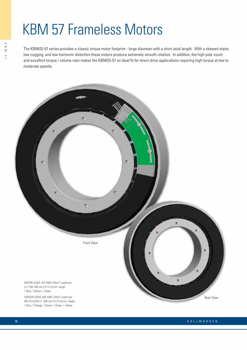
KBM 57 Frameless MotorsThe KBM(S)-57 series provides a classic torque motor footprint - large diameter with a short axial length. With a skewed stator, low cogging, and low harmonic distortion these motors produce extremely smooth rotation. In addition, the high pole count and excellent torque / volume ratio makes the KBM(S)-57 an ideal fit for direct drive applications requiring high torque at low to moderate speeds.
KB
M
57
36 K O L L M O R G E N
MOTOR LEADS: #16 AWG Teflon® coated per UL 1199, 400 mm [15.75 in] min. length,1-Blue, 1-Brown, 1-Violet
SENSOR LEADS: #26 AWG Teflon® coated per MIL-W-22759/11, 400 mm [15.75 in] min. length,1-Blue, 1-Orange, 1-Brown, 1-Green, 1-Yellow
Rear View
Front View
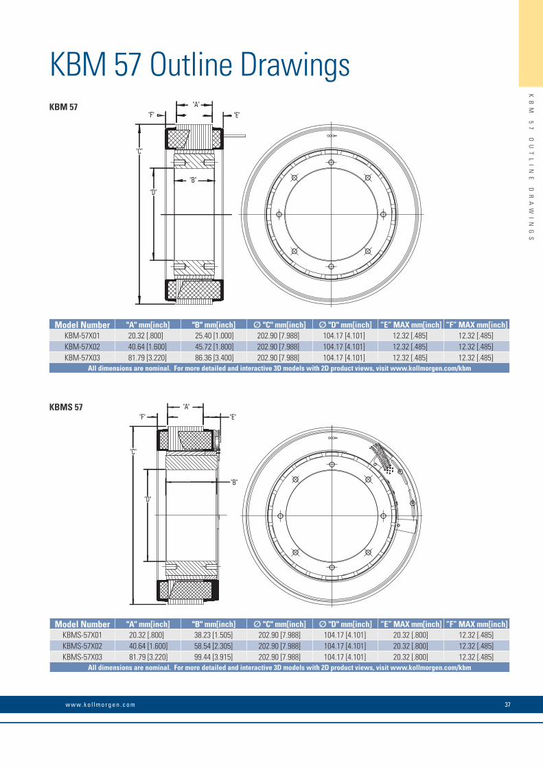
KBM 57 Outline Drawings
KB
M
57
O
UT
LI
NE
D
RA
WI
NG
S
37w w w. k o l l m o r g e n . c o m
"C"
"D"
"F" "E""A"
"B"
"B"
"C"
"D"
"F" "E""A"
KBM 57
KBMS 57
Model Number "A" mm[inch] "B" mm[inch] Ø "C" mm[inch] Ø "D" mm[inch] “E” MAX mm[inch] “F” MAX mm[inch]KBM-57X01 20.32 [.800] 25.40 [1.000] 202.90 [7.988] 104.17 [4.101] 12.32 [.485] 12.32 [.485]KBM-57X02 40.64 [1.600] 45.72 [1.800] 202.90 [7.988] 104.17 [4.101] 12.32 [.485] 12.32 [.485]KBM-57X03 81.79 [3.220] 86.36 [3.400] 202.90 [7.988] 104.17 [4.101] 12.32 [.485] 12.32 [.485]
All dimensions are nominal. For more detailed and interactive 3D models with 2D product views, visit www.kollmorgen.com/kbm
Model Number "A" mm[inch] "B" mm[inch] Ø "C" mm[inch] Ø "D" mm[inch] “E” MAX mm[inch] “F” MAX mm[inch]KBMS-57X01 20.32 [.800] 38.23 [1.505] 202.90 [7.988] 104.17 [4.101] 20.32 [.800] 12.32 [.485]KBMS-57X02 40.64 [1.600] 58.54 [2.305] 202.90 [7.988] 104.17 [4.101] 20.32 [.800] 12.32 [.485]KBMS-57X03 81.79 [3.220] 99.44 [3.915] 202.90 [7.988] 104.17 [4.101] 20.32 [.800] 12.32 [.485]
All dimensions are nominal. For more detailed and interactive 3D models with 2D product views, visit www.kollmorgen.com/kbm
38 K O L L M O R G E N
KB
M
57
P
ER
FO
RM
AN
CE
C
UR
VE
S
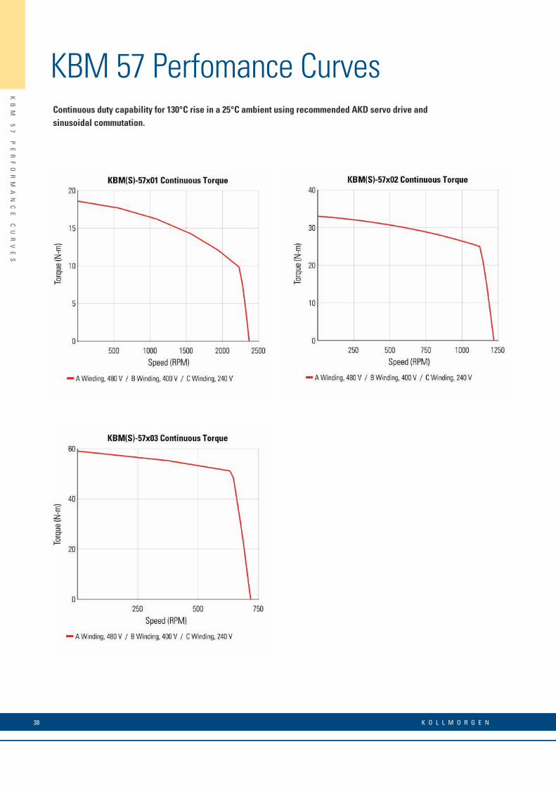
KBM 57 Perfomance CurvesContinuous duty capability for 130°C rise in a 25°C ambient using recommended AKD servo drive and sinusoidal commutation.

39w w w. k o l l m o r g e n . c o m
KB
M
57
P
ER
FO
RM
AN
CE
D
AT
A
KBM 57 Perfomance Data
* Notes 1) Winding temperature = 155°C at continuous stall, at rated output, and for performance curves. 2) To calculate no-load Kt and Kb at 25°C, multiply by 1.064. 3) Back EMF is peak (not RMS). 4) TPR assumes motor is housed and mounted to a 12" x 12" x 3/4" heat sink or equivalent. 5) Peak torque may be limited by AKD servo drive current, see page 11 for drive ratings or visit www.kollmorgen.com.
KBM(S) Frameless Motor SeriesKBM(S)-57XXX PERFORMANCE DATA & MOTOR PARAMETERS
Motor Parameter Symbol UnitsKBM(S)-57X01-X KBM(S)-57X02-X KBM(S)-57X03-X
A B C A B C A B C
Continuous Stall Torque at 25°C Amb. (1) Tc
N-m 18.8 18.8 18.8 33.5 33.5 33.5 60.0 60.0 60.0
lb-ft 13.9 13.9 13.9 24.7 24.7 24.7 44.2 44.2 44.2
Continuous Current Ic Arms 5.68 6.90 11.4 5.23 6.24 11.0 5.47 6.70 11.0
Peak Stall Torque (25°C winding temp) Tp
N-m 60.0 60.0 60.0 115 115 115 218 218 218
lb-ft 44.2 44.2 44.2 85.0 85.0 85.0 161 161 161
Peak Current Ip Arms 23.4 27.9 47.0 23.4 27.9 47.0 26.1 32.9 52.4
Rated Continuous Output Power at 25°C Amb. (1)
P Rated Watts 2310 2310 2310 2660 2660 2660 3000 3000 3000
HP Rated HP 3.10 3.10 3.10 3.57 3.57 3.57 4.02 4.02 4.00
Speed at Rated Power N Rated RPM 2050 2050 2050 1015 1015 1015 580 580 580
Torque Sensitivity (2) KtN-m / Arms 3.35 2.76 1.68 6.46 5.42 3.23 11.1 9.08 5.53
lb-ft / Arms 2.47 2.04 1.24 4.76 4.00 2.38 8.16 6.70 4.08
Back EMF Constant (3) Kb Vpk / kRPM 287 236 143 552 463 276 946 777 473
Motor Constant KmN-m/√watt 1.49 1.49 1.49 2.51 2.51 2.51 3.71 3.71 3.71
lb-ft /√watt 1.10 1.10 1.10 1.85 1.85 1.85 2.74 2.74 2.74
Resistance (line to line) Rm Ohms 3.39 2.21 0.845 4.40 2.93 1.10 5.92 3.86 1.48
Inductance Lm mH 13 9.1 3.4 22 15 5.4 35 23 8.6
Inertia (KBM) JmKg-m² 6.56E-3 1.18E-2 2.21E-2
lb-ft-s² 4.84E-3 8.70E-3 1.63E-2
Weight (KBM) WtKg 4.54 7.89 14.5
lb 10.0 17.4 32.0
Inertia (KBMS) JmKg-m² 9.49E-3 1.49E-2 2.52E-2
lb-ft-s² 7.00E-3 1.10E-2 1.86E-2
Weight (KBMS) WtKg 5.31 8.62 15.4
lb 11.7 19.0 34.0
Max Static Friction TfN-m 0.176 0.285 0.556
lb-ft 0.130 0.210 0.410
Cogging Friction (peak-to-peak) Tcog
N-m 0.088 0.149 0.285
lb-ft 0.065 0.110 0.210
Viscous Damping FiN-m/ kRPM 6.51 3.97 3.99
lb-ft / kRPM 4.80 2.93 2.94
Thermal Resistance (4) TPR °C / watt 0.530 0.480 0.326
Number of Poles P - 24 24 24
Recommended Drive AKD- _ _ _ _ _ 00607 01207 02406 00607 01207 02406 00607 01207 02406
Voltage Req’d at Rated Output Vac Input VAC 480 400 240 480 400 240 480 400 240
Peak Stall Torque (5) (Motor with AKD servo drive) Tp Drive
N-m 46.1 60.0 60.0 100 115 115 175 198 205
lb-ft 34.0 44.2 44.2 73.8 85.0 85.0 129 146 151
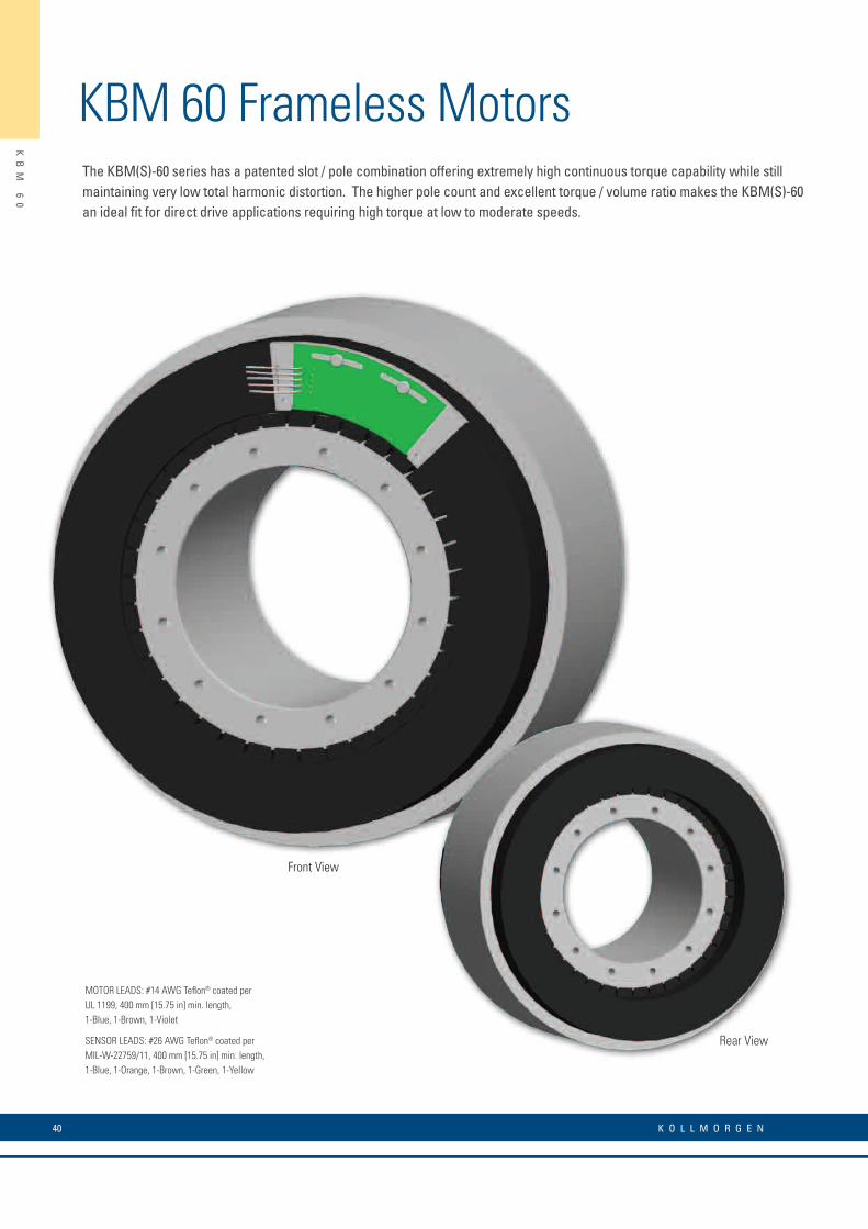
KBM 60 Frameless MotorsThe KBM(S)-60 series has a patented slot / pole combination offering extremely high continuous torque capability while still maintaining very low total harmonic distortion. The higher pole count and excellent torque / volume ratio makes the KBM(S)-60 an ideal fit for direct drive applications requiring high torque at low to moderate speeds.
KB
M
60
40 K O L L M O R G E N
MOTOR LEADS: #14 AWG Teflon® coated per UL 1199, 400 mm [15.75 in] min. length,1-Blue, 1-Brown, 1-Violet
SENSOR LEADS: #26 AWG Teflon® coated per MIL-W-22759/11, 400 mm [15.75 in] min. length,1-Blue, 1-Orange, 1-Brown, 1-Green, 1-Yellow
Rear View
Front View
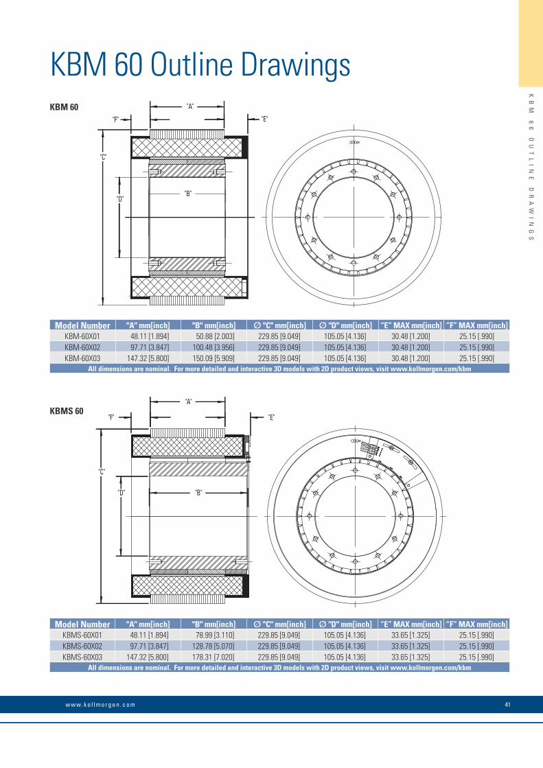
KBM 60 Outline Drawings
KB
M
60
O
UT
LI
NE
D
RA
WI
NG
S
41w w w. k o l l m o r g e n . c o m
"F"
"A"
"E"
"C"
"D""B"
KBM 60
Model Number "A" mm[inch] "B" mm[inch] Ø "C" mm[inch] Ø "D" mm[inch] “E” MAX mm[inch] “F” MAX mm[inch]KBM-60X01 48.11 [1.894] 50.88 [2.003] 229.85 [9.049] 105.05 [4.136] 30.48 [1.200] 25.15 [.990]KBM-60X02 97.71 [3.847] 100.48 [3.956] 229.85 [9.049] 105.05 [4.136] 30.48 [1.200] 25.15 [.990]KBM-60X03 147.32 [5.800] 150.09 [5.909] 229.85 [9.049] 105.05 [4.136] 30.48 [1.200] 25.15 [.990]
All dimensions are nominal. For more detailed and interactive 3D models with 2D product views, visit www.kollmorgen.com/kbm
"C"
"D"
"F"
"A"
"E"
"B"
KBMS 60
Model Number "A" mm[inch] "B" mm[inch] Ø "C" mm[inch] Ø "D" mm[inch] “E” MAX mm[inch] “F” MAX mm[inch]KBMS-60X01 48.11 [1.894] 78.99 [3.110] 229.85 [9.049] 105.05 [4.136] 33.65 [1.325] 25.15 [.990]KBMS-60X02 97.71 [3.847] 128.78 [5.070] 229.85 [9.049] 105.05 [4.136] 33.65 [1.325] 25.15 [.990]KBMS-60X03 147.32 [5.800] 178.31 [7.020] 229.85 [9.049] 105.05 [4.136] 33.65 [1.325] 25.15 [.990]
All dimensions are nominal. For more detailed and interactive 3D models with 2D product views, visit www.kollmorgen.com/kbm
42 K O L L M O R G E N
KB
M
60
P
ER
FO
RM
AN
CE
C
UR
VE
S
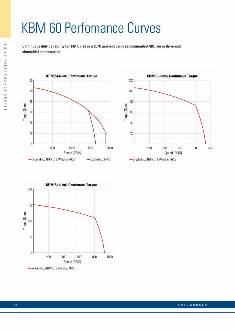
KBM 60 Perfomance CurvesContinuous duty capability for 130°C rise in a 25°C ambient using recommended AKD servo drive and sinusoidal commutation.

43w w w. k o l l m o r g e n . c o m
KB
M
60
P
ER
FO
RM
AN
CE
D
AT
A
KBM 60 Perfomance Data
* Notes 1) Winding temperature = 155°C at continuous stall, at rated output, and for performance curves. 2) To calculate no-load Kt and Kb at 25°C, multiply by 1.064. 3) Back EMF is peak (not RMS). 4) TPR assumes motor is housed and mounted to a 12" x 12" x 3/4" heat sink or equivalent. 5) Peak torque may be limited by AKD servo drive current, see page 11 for drive ratings or visit www.kollmorgen.com.
KBM(S) Frameless Motor SeriesKBM(S)-60XXX PERFORMANCE DATA & MOTOR PARAMETERS
Motor Parameter Symbol UnitsKBM(S)-60X01-X KBM(S)-60X02-X KBM(S)-60X03-X
A B C A B A B
Continuous Stall Torque at 25°C Amb. (1) Tc
N-m 53.9 53.9 53.9 108 108 154 154
lb-ft 39.8 39.8 39.8 79.7 79.7 114 114
Continuous Current Ic Arms 13.7 16.9 22.7 16.3 19.6 18.6 24.0
Peak Stall Torque(25°C winding temp) Tp
N-m 127 127 127 255 255 393 393
lb-ft 93.8 93.8 93.8 188 188 290 290
Peak Current Ip Arms 40.0 50.4 78.0 50.4 60.4 63.3 76.8
Rated Continuous Output Power at 25°C Amb. (1)
P Rated Watts 4165 4165 4580 6985 6985 8350 8420
HP Rated HP 5.58 5.58 6.14 9.36 9.36 11.2 11.3
Speed at Rated Power N Rated RPM 1600 1600 1300 885 885 720 730
Torque Sensitivity (2) KtN-m / Arms 4.04 3.27 2.43 6.79 5.66 8.50 7.01
lb-ft / Arms 2.98 2.41 1.80 5.01 4.17 6.27 5.17
Back EMF Constant (3) Kb Vpk / kRPM 345 280 208 581 484 727 600
Motor Constant KmN-m/√watt 3.44 3.44 3.44 5.78 5.78 7.46 7.39
lb-ft /√watt 2.54 2.54 2.54 4.26 4.26 5.50 5.45
Resistance (line to line) Rm Ohms 0.916 0.590 0.335 0.921 0.638 0.867 0.600
Inductance Lm mH 8.0 5.1 2.8 11 7.6 11 7.5
Inertia (KBM) JmKg-m² 1.63E-3 3.17E-2 4.75E-2
lb-ft-s² 1.20E-2 2.34E-2 3.50E-2
Weight (KBM) WtKg 13.2 25.2 37.2
lb 29.0 55.6 82.0
Inertia (KBMS) JmKg-m² 2.56E-2 4.20E-2 5.29E-2
lb-ft-s² 1.89E-2 3.10E-2 3.90E-2
Weight (KBMS) WtKg 15.3 27.9 39.8
lb 33.8 61.4 87.7
Max Static Friction TfN-m 1.36 2.71 4.07
lb-ft 1.00 2.00 3.00
Cogging Friction (peak-to-peak) Tcog
N-m 1.02 2.03 3.05
lb-ft 0.750 1.50 2.25
Viscous Damping FiN-m/ kRPM 0.230 0.461 0.691
lb-ft / kRPM 0.170 0.340 0.510
Thermal Resistance (4) TPR °C / watt 0.336 0.236 0.192
Number of Poles P - 38 38 38
Recommended Drive AKD- _ _ _ _ _ 02407 02407 02406 02407 02407 02407 04807
Voltage Req’d at Rated Output Vac Input VAC 480 400 240 480 400 480 400
Peak Stall Torque (5) (Motor with AKD servo drive) Tp Drive
N-m 127 121 106 248 221 330 393
lb-ft 93.8 89.2 78.2 183 163 243 290
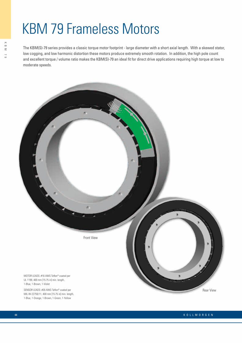
KBM 79 Frameless MotorsThe KBM(S)-79 series provides a classic torque motor footprint - large diameter with a short axial length. With a skewed stator, low cogging, and low harmonic distortion these motors produce extremely smooth rotation. In addition, the high pole count and excellent torque / volume ratio makes the KBM(S)-79 an ideal fit for direct drive applications requiring high torque at low to moderate speeds.
KB
M
79
44 K O L L M O R G E N
MOTOR LEADS: #16 AWG Teflon® coated perUL 1199, 400 mm [15.75 in] min. length,1-Blue, 1-Brown, 1-Violet
SENSOR LEADS: #26 AWG Teflon® coated per MIL-W-22759/11, 400 mm [15.75 in] min. length,1-Blue, 1-Orange, 1-Brown, 1-Green, 1-Yellow
Rear View
Front View

KBM 79 Outline Drawings
KB
M
79
O
UT
LI
NE
D
RA
WI
NG
S
45w w w. k o l l m o r g e n . c o m
"B"
"C"
"D"
"F""A"
"E"
"B""D"
"C"
"F""A"
"E"
KBM 79
KBMS 79
Model Number "A" mm[inch] "B" mm[inch] Ø "C" mm[inch] Ø "D" mm[inch] “E” MAX mm[inch] “F” MAX mm[inch]KBM-79X01 31.75 [1.250] 38.10 [1.500] 259.63 [10.221] 152.43 [6.001] 13.34 [.525] 13.34 [.525]KBM-79X02 63.50 [2.500] 69.85 [2.750] 259.63 [10.221] 152.43 [6.001] 13.34 [.525] 13.34 [.525]KBM-79X03 127.00 [5.000] 133.35 [5.250] 259.63 [10.221] 152.43 [6.001] 13.34 [.525] 13.34 [.525]
All dimensions are nominal. For more detailed and interactive 3D models with 2D product views, visit www.kollmorgen.com/kbm
Model Number "A" mm[inch] "B" mm[inch] Ø "C" mm[inch] Ø "D" mm[inch] “E” MAX mm[inch] “F” MAX mm[inch]KBMS-79X01 31.75 [1.250] 52.07 [2.050] 259.63 [10.221] 152.43 [6.001] 21.20 [.835] 13.34 [.525]KBMS-79X02 63.50 [2.500] 83.82 [3.300] 259.63 [10.221] 152.43 [6.001] 21.20 [.835] 13.34 [.525]KBMS-79X03 127.00 [5.000] 147.07 [5.790] 259.63 [10.221] 152.43 [6.001] 21.20 [.835] 13.34 [.525]
All dimensions are nominal. For more detailed and interactive 3D models with 2D product views, visit www.kollmorgen.com/kbm
46 K O L L M O R G E N
KB
M
79
P
ER
FO
RM
AN
CE
C
UR
VE
S
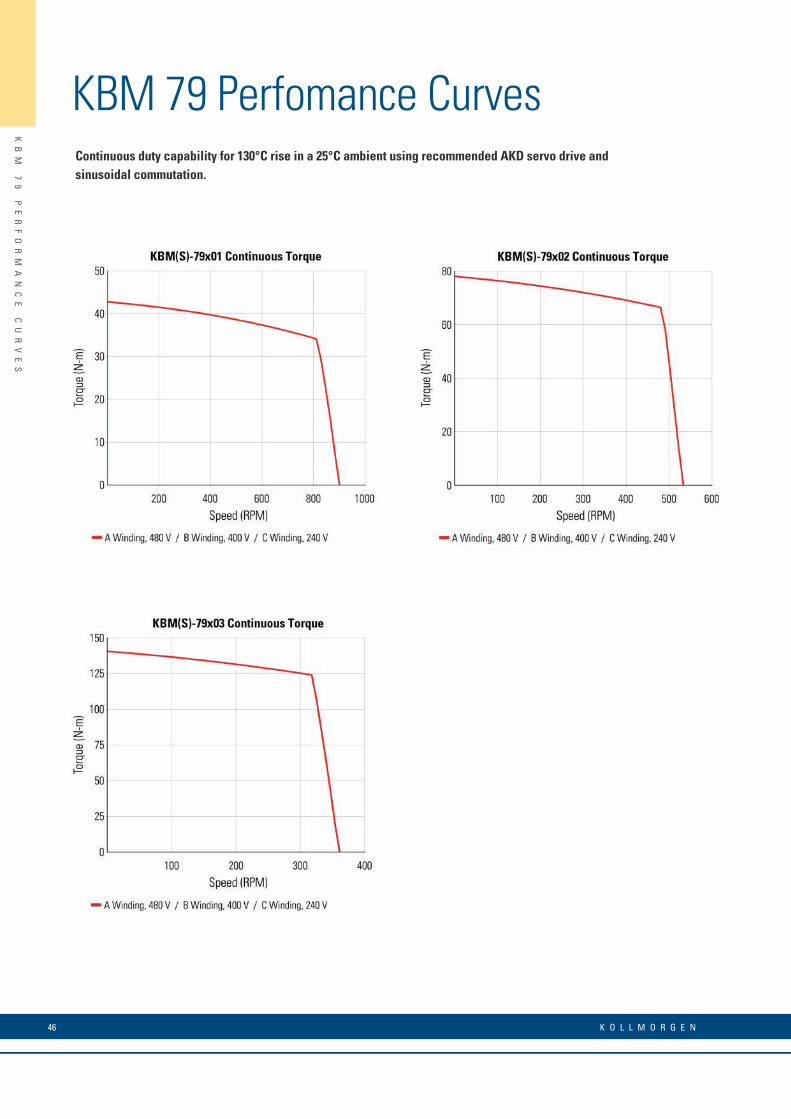
KBM 79 Perfomance CurvesContinuous duty capability for 130°C rise in a 25°C ambient using recommended AKD servo drive and sinusoidal commutation.
47w w w. k o l l m o r g e n . c o m
KB
M
79
P
ER
FO
RM
AN
CE
D
AT
A
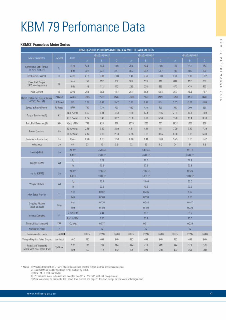
KBM 79 Perfomance DataKBM(S) Frameless Motor Series
KBM(S)-79XXX PERFORMANCE DATA & MOTOR PARAMETERS
Motor Parameter Symbol UnitsKBM(S)-79X01-X KBM(S)-79X02-X KBM(S)-79X03-X
A B C A B C A B C
Continuous Stall Torque at 25°C Amb. (1) Tc
N-m 43.5 43.5 43.5 79.6 79.6 79.6 143 143 143
lb-ft 32.1 32.1 32.1 58.7 58.7 58.7 106 106 106
Continuous Current Ic Arms 4.95 6.00 10.0 5.40 6.50 11.0 6.76 8.00 13.2
Peak Stall Torque (25°C winding temp) Tp
N-m 152 152 152 319 319 319 637 637 637
lb-ft 112 112 112 235 235 235 470 470 470
Peak Current Ip Arms 20.8 25.3 41.7 26.1 31.4 52.4 36.7 46.3 73.7
Rated Continuous Output Power at 25°C Amb. (1)
P Rated Watts 2585 2585 2585 2920 2920 2920 3750 3750 3640
HP Rated HP 3.47 3.47 3.47 3.91 3.91 3.91 5.03 5.03 4.88
Speed at Rated Power N Rated RPM 730 730 730 430 430 430 300 300 290
Torque Sensitivity (2) KtN-m / Arms 8.87 7.34 4.43 14.9 12.4 7.46 21.4 18.1 11.0
lb-ft / Arms 6.54 5.42 3.27 11.0 9.17 5.50 15.8 13.4 8.10
Back EMF Constant (3) Kb Vpk / kRPM 758 628 379 1275 1062 637 1832 1550 939
Motor Constant KmN-m/√watt 2.89 2.89 2.89 4.81 4.81 4.81 7.29 7.29 7.29
lb-ft/√watt 2.13 2.13 2.13 3.55 3.55 3.55 5.38 5.38 5.38
Resistance (line to line) Rm Ohms 6.26 4.25 1.56 6.40 4.44 1.60 5.75 3.86 1.47
Inductance Lm mH 23 16 5.8 32 22 8.0 34 24 8.9
Inertia (KBM) JmKg-m² 3.25E-2 5.97E-2 0.114
lb-ft-s² 2.40E-2 4.40E-2 8.40E-2
Weight (KBM) WtKg 9.21 16.9 32.1
lb 20.3 37.3 70.8
Inertia (KBMS) JmKg-m² 4.45E-2 7.15E-2 0.125
lb-ft-s² 3.28E-2 5.27E-2 9.20E-2
Weight (KBMS) WtKg 10.7 18.40 33.5
lb 23.5 40.5 73.9
Max Static Friction TfN-m 0.407 0.746 1.36
lb-ft 0.300 0.550 1.00
Cogging Friction (peak-to-peak) Tcog
N-m 0.136 0.244 0.447
lb-ft 0.100 0.180 0.330
Viscous Damping FiN-m/kRPM 2.44 15.5 31.2
lb-ft /kRPM 1.80 11.4 23.0
Thermal Resistance (4) TPR °C / watt 0.377 0.311 0.220
Number of Poles P - 32 32 32
Recommended Drive AKD- _ _ _ _ _ 00607 01207 02406 00607 01207 02406 01207 01207 02406
Voltage Req’d at Rated Output Vac Input VAC 480 400 240 480 400 240 480 400 240
Peak Stall Torque (5) (Motor with AKD servo drive) Tp Drive
N-m 144 152 152 250 310 296 550 475 475
lb-ft 106 112 112 184 228 218 406 350 350
* Notes 1) Winding temperature = 155°C at continuous stall, at rated output, and for performance curves. 2) To calculate no-load Kt and Kb at 25°C, multiply by 1.064. 3) Back EMF is peak (not RMS). 4) TPR assumes motor is housed and mounted to a 12" x 12" x 3/4" heat sink or equivalent. 5) Peak torque may be limited by AKD servo drive current, see page 11 for drive ratings or visit www.kollmorgen.com.
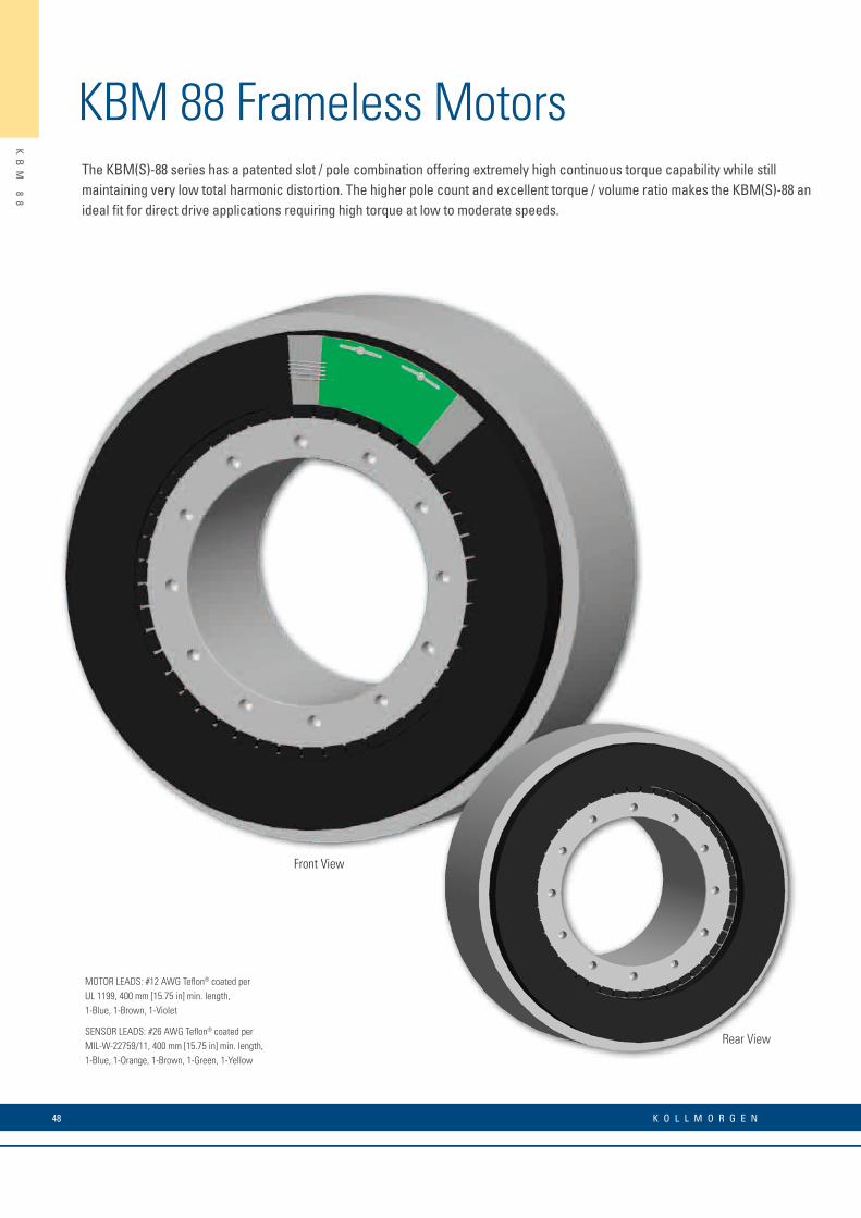
KBM 88 Frameless MotorsThe KBM(S)-88 series has a patented slot / pole combination offering extremely high continuous torque capability while still maintaining very low total harmonic distortion. The higher pole count and excellent torque / volume ratio makes the KBM(S)-88 an ideal fit for direct drive applications requiring high torque at low to moderate speeds.
KB
M
88
48 K O L L M O R G E N
MOTOR LEADS: #12 AWG Teflon® coated per UL 1199, 400 mm [15.75 in] min. length,1-Blue, 1-Brown, 1-Violet
SENSOR LEADS: #26 AWG Teflon® coated per MIL-W-22759/11, 400 mm [15.75 in] min. length,1-Blue, 1-Orange, 1-Brown, 1-Green, 1-Yellow
Rear View
Front View
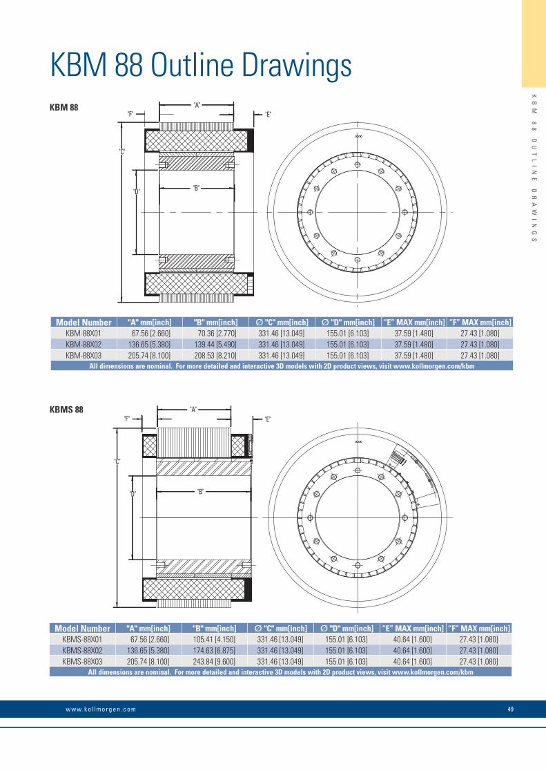
KBM 88 Outline Drawings
KB
M
88
O
UT
LI
NE
D
RA
WI
NG
S
49w w w. k o l l m o r g e n . c o m
Rear View
"D"
"C"
"F""A"
"E"
"B"
"B""D"
"C"
"F""A"
"E"
KBM 88
KBMS 88
Model Number "A" mm[inch] "B" mm[inch] Ø "C" mm[inch] Ø "D" mm[inch] “E” MAX mm[inch] “F” MAX mm[inch]KBM-88X01 67.56 [2.660] 70.36 [2.770] 331.46 [13.049] 155.01 [6.103] 37.59 [1.480] 27.43 [1.080]KBM-88X02 136.65 [5.380] 139.44 [5.490] 331.46 [13.049] 155.01 [6.103] 37.59 [1.480] 27.43 [1.080]KBM-88X03 205.74 [8.100] 208.53 [8.210] 331.46 [13.049] 155.01 [6.103] 37.59 [1.480] 27.43 [1.080]
All dimensions are nominal. For more detailed and interactive 3D models with 2D product views, visit www.kollmorgen.com/kbm
Model Number "A" mm[inch] "B" mm[inch] Ø "C" mm[inch] Ø "D" mm[inch] “E” MAX mm[inch] “F” MAX mm[inch]KBMS-88X01 67.56 [2.660] 105.41 [4.150] 331.46 [13.049] 155.01 [6.103] 40.64 [1.600] 27.43 [1.080]KBMS-88X02 136.65 [5.380] 174.63 [6.875] 331.46 [13.049] 155.01 [6.103] 40.64 [1.600] 27.43 [1.080]KBMS-88X03 205.74 [8.100] 243.84 [9.600] 331.46 [13.049] 155.01 [6.103] 40.64 [1.600] 27.43 [1.080]
All dimensions are nominal. For more detailed and interactive 3D models with 2D product views, visit www.kollmorgen.com/kbm
50 K O L L M O R G E N
KB
M
88
P
ER
FO
RM
AN
CE
C
UR
VE
S
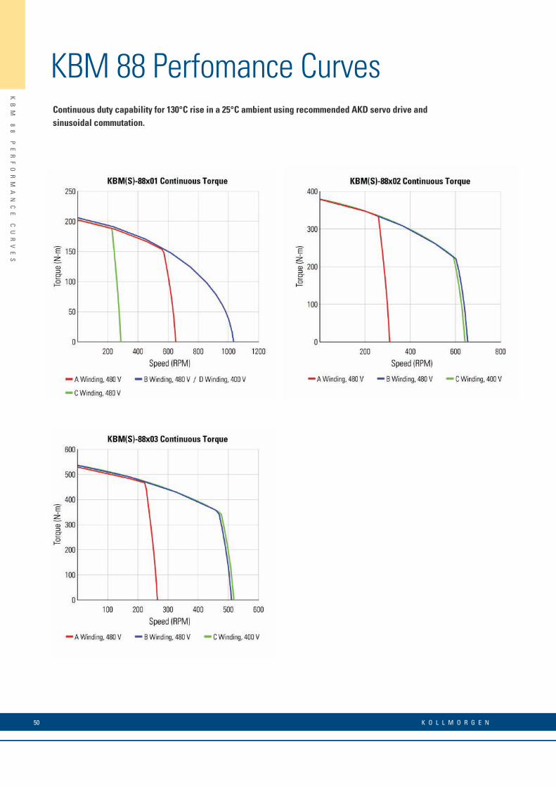
KBM 88 Perfomance CurvesContinuous duty capability for 130°C rise in a 25°C ambient using recommended AKD servo drive and sinusoidal commutation.

51w w w. k o l l m o r g e n . c o m
KB
M
88
P
ER
FO
RM
AN
CE
D
AT
A
KBM 88 Perfomance Data
* Notes 1) Winding temperature = 155°C at continuous stall, at rated output, and for performance curves. 2) To calculate no-load Kt and Kb at 25°C, multiply by 1.064. 3) Back EMF is peak (not RMS). 4) TPR assumes motor is housed and mounted to a 20" x 20" x 3/4" heat sink or equivalent. 5) Peak torque may be limited by AKD servo drive current, see page 11 for drive ratings or visit www.kollmorgen.com.
KBM(S) Frameless Motor SeriesKBM(S)-88XXX PERFORMANCE DATA & MOTOR PARAMETERS
Motor Parameter Symbol UnitsKBM(S)-88X01-X KBM(S)-88X02-X KBM(S)-88X03-X
A B C D A B C A B C
Continuous Stall Torque at 25°C Amb. (1) Tc
N-m 205 209 205 207 385 385 385 538 545 545
lb-ft 151 154 151 153 284 284 284 397 402 402
Continuous Current Ic Arms 17.1 32.1 7.50 40.2 15.1 32.1 37.9 18.2 35.5 45.2
Peak Stall Torque (25°C winding temp) Tp
N-m 414 414 414 414 789 789 789 1200 1200 1200
lb-ft 305 305 305 305 582 582 582 885 885 885
Peak Current Ip Arms 40.0 75.4 17.8 94.7 40.0 75.4 89.0 53.1 106 134
Rated Continuous Output Power at 25°C Amb. (1)
P Rated Watts 8250 6600 3870 6600 7950 13430 13430 10450 16000 16000
HP Rated HP 11.1 8.85 5.19 8.85 10.7 18.0 18.0 14.0 21.4 21.4
Speed at Rated Power N Rated RPM 520 940 205 940 235 550 550 225 425 425
Torque Sensitivity (2) KtN-m / Arms 12.2 6.57 27.7 5.18 25.7 12.1 10.3 30.0 15.5 12.8
lb-ft / Arms 9.00 4.85 20.5 3.82 19.0 8.95 7.59 22.1 11.5 9.4
Back EMF Constant (3) Kb Vpk / kRPM 1044 562 2372 443 2201 1037 880 2563 1329 1092
Motor Constant KmN-m/√watt 10.3 10.5 10.2 10.4 16.3 16.3 16.3 20.6 20.9 20.9
lb-ft /√watt 7.62 7.75 7.60 7.70 12.0 12.0 12.0 15.2 15.4 15.4
Resistance (line to line) Rm Ohms 0.930 0.261 4.90 0.164 1.66 0.369 0.262 1.41 0.370 0.250
Inductance Lm mH 13 3.7 67 2.3 29 6.4 4.6 26 7.0 4.7
Inertia (KBM) JmKg-m² 9.84E-2 0.198 0.298
lb-ft-s² 7.26E-2 0.146 0.220
Weight (KBM) WtKg 37.6 72.6 106
lb 83.0 160 234
Inertia (KBMS) JmKg-m² 0.146 0.247 0.315
lb-ft-s² 0.108 0.182 0.232
Weight (KBMS) WtKg 42.6 77.6 111
lb 94.0 171 245
Max Static Friction TfN-m 2.17 4.34 6.51
lb-ft 1.60 3.20 4.80
Cogging Friction (peak-to-peak) Tcog
N-m 1.63 3.25 4.88
lb-ft 1.20 2.40 3.60
Viscous Damping FiN-m/ kRPM 0.773 1.53 2.30
lb-ft / kRPM 0.570 1.13 1.70
Thermal Resistance (4) TPR °C / watt 0.215 0.152 0.124
Number of Poles P - 46 46 46
Recommended Drive AKD- _ _ _ _ _ 02407 04807 01207 04807 02407 04807 04807 02407 04807 04807
Voltage Req’d at Rated Output Vac Input VAC 480 480 480 400 480 480 400 480 480 400
Peak Stall Torque (5) (Motor with AKD servo drive) Tp Drive
N-m 414 414 414 414 789 789 789 1150 1120 1018
lb-ft 305 305 305 305 582 582 582 848 826 750
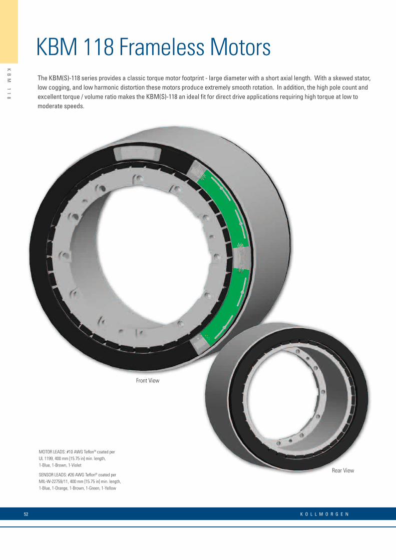
KBM 118 Frameless MotorsThe KBM(S)-118 series provides a classic torque motor footprint - large diameter with a short axial length. With a skewed stator, low cogging, and low harmonic distortion these motors produce extremely smooth rotation. In addition, the high pole count and excellent torque / volume ratio makes the KBM(S)-118 an ideal fit for direct drive applications requiring high torque at low to moderate speeds.
KB
M
11
8
52 K O L L M O R G E N
MOTOR LEADS: #10 AWG Teflon® coated per UL 1199, 400 mm [15.75 in] min. length,1-Blue, 1-Brown, 1-Violet
SENSOR LEADS: #26 AWG Teflon® coated per MIL-W-22759/11, 400 mm [15.75 in] min. length,1-Blue, 1-Orange, 1-Brown, 1-Green, 1-Yellow
Rear View
Front View
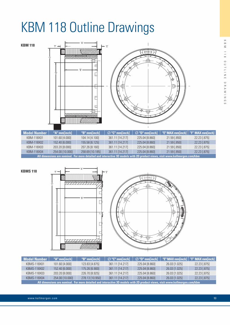
KBM 118 Outline Drawings
KB
M
11
8
OU
TL
IN
E
DR
AW
IN
GS
53w w w. k o l l m o r g e n . c o m
"B"
"F""A"
"E"
"C"
"D"
"B"
"F""A"
"E"
"C"
"D"
KBM 118
KBMS 118
Model Number "A" mm[inch] "B" mm[inch] Ø "C" mm[inch] Ø "D" mm[inch] "E" MAX mm[inch] “F” MAX mm[inch]KBM-118X01 101.60 [4.000] 104.14 [4.100] 361.11 [14.217] 225.04 [8.860] 21.59 [.850] 22.23 [.875]KBM-118X02 152.40 [6.000] 155.58 [6.125] 361.11 [14.217] 225.04 [8.860] 21.59 [.850] 22.23 [.875]KBM-118X03 203.20 [8.000] 207.26 [8.160] 361.11 [14.217] 225.04 [8.860] 21.59 [.850] 22.23 [.875]KBM-118X04 254.00 [10.000] 258.69 [10.185] 361.11 [14.217] 225.04 [8.860] 21.59 [.850] 22.23 [.875]
All dimensions are nominal. For more detailed and interactive 3D models with 2D product views, visit www.kollmorgen.com/kbm
Model Number "A" mm[inch] "B" mm[inch] Ø "C" mm[inch] Ø "D" mm[inch] "E" MAX mm[inch] “F” MAX mm[inch]KBMS-118X01 101.60 [4.000] 123.83 [4.875] 361.11 [14.217] 225.04 [8.860] 26.03 [1.025] 22.23 [.875]KBMS-118X02 152.40 [6.000] 175.26 [6.900] 361.11 [14.217] 225.04 [8.860] 26.03 [1.025] 22.23 [.875]KBMS-118X03 203.20 [8.000] 226.70 [8.925] 361.11 [14.217] 225.04 [8.860] 26.03 [1.025] 22.23 [.875]KBMS-118X04 254.00 [10.000] 278.13 [10.950] 361.11 [14.217] 225.04 [8.860] 26.03 [1.025] 22.23 [.875]
All dimensions are nominal. For more detailed and interactive 3D models with 2D product views, visit www.kollmorgen.com/kbm
54 K O L L M O R G E N
KB
M
11
8
PE
RF
OR
MA
NC
E
CU
RV
ES
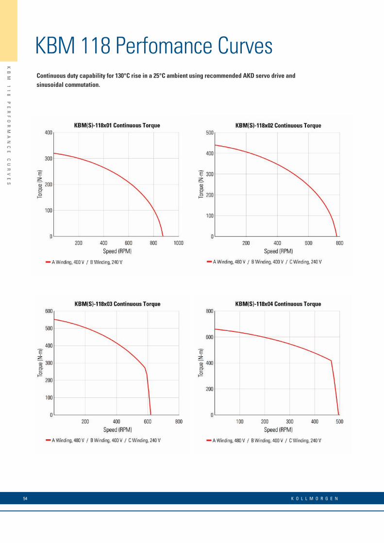
KBM 118 Perfomance CurvesContinuous duty capability for 130°C rise in a 25°C ambient using recommended AKD servo drive and sinusoidal commutation.

55w w w. k o l l m o r g e n . c o m
KB
M
11
8
PE
RF
OR
MA
NC
E
DA
TA
KBM 118 Perfomance Data
* Notes 1) Winding temperature = 155°C at continuous stall, at rated output, and for performance curves. 2) To calculate no-load Kt and Kb at 25°C, multiply by 1.064. 3) Back EMF is peak (not RMS). 4) TPR assumes the motor is housed and mounted to a heat sink. 5) Peak torque may be limited by AKD servo drive current, see page 11 for drive ratings or visit www.kollmorgen.com.
KBM(S) Frameless Motor SeriesKBM(S)-118XXX PERFORMANCE DATA & MOTOR PARAMETERS
Motor Parameter Symbol UnitsKBM(S)-118X01-X KBM(S)-118X02-X KBM(S)-118X03-X KBM(S)-118X04-X
A B A B C A B C A B C
Continuous Stall Torque at 25°C Amb. (1) Tc
N-m 325 325 446 446 446 560 560 560 672 672 672
lb-ft 239 239 329 329 329 413 413 413 495 495 495
Continuous Current Ic Arms 43.7 76.5 47.0 57.0 94.5 44.0 54.0 89.5 42.8 51.5 86.0
Peak Stall Torque (25°C winding temp) Tp
N-m 994 994 1451 1451 1451 1932 1932 1932 2400 2400 2400
lb-ft 733 733 1070 1070 1070 1425 1425 1425 1770 1770 1770
Peak Current Ip Arms 151 265 171 206 343 171 206 343 171 206 343.0
Rated Continuous Output Power at 25°C Amb. (1)
P Rated Watts 9000 9000 10350 10350 10350 17000 17000 17000 19850 19850 19850
HP Rated HP 12.1 12.1 13.9 13.9 13.9 22.8 22.8 22.8 26.6 26.6 26.6
Speed at Rated Power N Rated RPM 785 785 710 710 710 535 535 535 420 420 420
Torque Sensitivity (2) KtN-m / Arms 7.58 4.33 9.66 8.05 4.83 12.8 10.7 6.40 16.0 13.4 8.00
lb-ft / Arms 5.59 3.20 7.13 5.94 3.56 9.46 7.88 4.72 11.8 9.8 5.90
Back EMF Constant (3) Kb Vpk / kRPM 648 371 826 689 413 1096 913 547 1371 1142 684
Motor Constant KmN-m/√watt 11.8 11.8 14.6 14.6 14.6 17.1 17.1 17.1 19.4 19.4 19.4
lb-ft /√watt 8.70 8.70 10.8 10.8 10.8 12.6 12.6 12.6 14.3 14.3 14.3
Resistance (line to line) Rm Ohms 0.276 0.088 0.292 0.191 0.073 0.373 0.259 0.093 0.455 0.298 0.112
Inductance Lm mH 2.5 0.82 2.7 1.9 0.70 4.3 3.0 1.1 4.5 3.0 1.2
Inertia (KBM) JmKg-m² 0.267 0.396 0.542 0.648
lb-ft-s² 0.197 0.292 0.400 0.478
Weight (KBM) WtKg 37.1 53.5 71.7 88.5
lb 81.8 118 158 195
Inertia (KBMS) JmKg-m² 0.315 0.403 0.591 0.698
lb-ft-s² 0.232 0.297 0.436 0.515
Weight (KBMS) WtKg 39.2 56.2 73.9 90.7
lb 86.4 124 163 200
Max Static Friction TfN-m 6.39 9.57 12.8 16.0
lb-ft 4.71 7.06 9.42 11.8
Cogging Friction (peak-to-peak) Tcog
N-m 3.16 4.79 6.39 8.13
lb-ft 2.33 3.53 4.71 6.00
Viscous Damping FiN-m/ kRPM 38.8 59.7 81.3 100
lb-ft / kRPM 28.6 44.0 60.0 74.0
Thermal Resistance (4) TPR °C / watt 0.110 0.089 0.078 0.069
Number of Poles P - 38 38 38 38
Recommended Drive AKD- _ _ _ _ _ 04807 09607 04807 09607 09607 04807 09607 09607 04807 09607 09607
Voltage Req’d at Rated Output Vac Input VAC 400 240 480 400 240 480 400 240 480 400 240
Peak Stall Torque (5) (Motor with AKD servo drive) Tp Drive
N-m 700 760 890 1380 895 1261 1835 1184 1470 2282 1485
lb-ft 516 560 656 1017 660 930 1352 874 1084 1682 1095
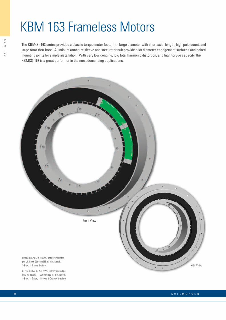
KBM 163 Frameless MotorsThe KBM(S)-163 series provides a classic torque motor footprint - large diameter with short axial length, high pole count, and large rotor thru-bore. Aluminum armature sleeve and steel rotor hub provide pilot diameter engagement surfaces and bolted mounting joints for simple installation. With very low cogging, low total harmonic distortion, and high torque capacity, the KBM(S)-163 is a great performer in the most demanding applications.
KB
M
16
3
56 K O L L M O R G E N
MOTOR LEADS: #10 AWG Teflon® insulatedper UL 1199, 900 mm [35 in] min. length,1-Blue, 1-Brown, 1-Violet
SENSOR LEADS: #26 AWG Teflon® coated per MIL-W-22759/11, 900 mm [35 in] min. length,1-Blue, 1-Green, 1-Brown, 1-Orange, 1-Yellow
Rear View
Front View
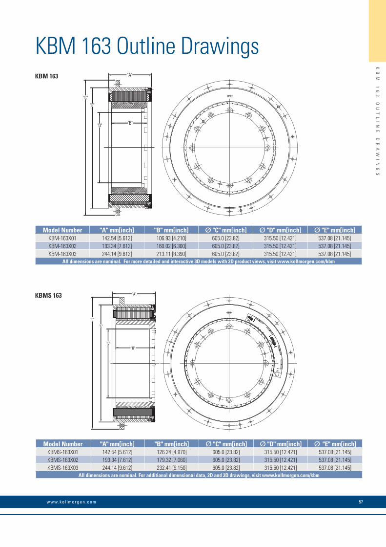
KBM 163 Outline Drawings
KB
M
16
3
OU
TL
IN
E
DR
AW
IN
GS
57w w w. k o l l m o r g e n . c o m
"A"
"B"
"C"
"D"
"E"
KBMS 163
Model Number "A" mm[inch] "B" mm[inch] Ø "C" mm[inch] Ø "D" mm[inch] Ø "E" mm[inch]KBMS-163X01 142.54 [5.612] 126.24 [4.970] 605.0 [23.82] 315.50 [12.421] 537.08 [21.145]KBMS-163X02 193.34 [7.612] 179.32 [7.060] 605.0 [23.82] 315.50 [12.421] 537.08 [21.145]KBMS-163X03 244.14 [9.612] 232.41 [9.150] 605.0 [23.82] 315.50 [12.421] 537.08 [21.145]
All dimensions are nominal. For additional dimensional data, 2D and 3D drawings, visit www.kollmorgen.com/kbm
"A"
"B"
"C"
"D"
"E"
KBM 163
Model Number "A" mm[inch] "B" mm[inch] Ø "C" mm[inch] Ø "D" mm[inch] Ø "E" mm[inch]KBM-163X01 142.54 [5.612] 106.93 [4.210] 605.0 [23.82] 315.50 [12.421] 537.08 [21.145]KBM-163X02 193.34 [7.612] 160.02 [6.300] 605.0 [23.82] 315.50 [12.421] 537.08 [21.145]KBM-163X03 244.14 [9.612] 213.11 [8.390] 605.0 [23.82] 315.50 [12.421] 537.08 [21.145]
All dimensions are nominal. For more detailed and interactive 3D models with 2D product views, visit www.kollmorgen.com/kbm
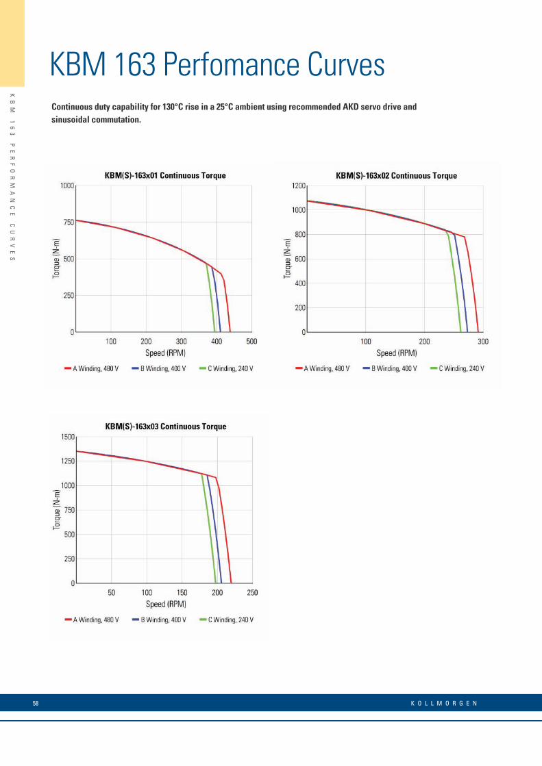
58 K O L L M O R G E N
KB
M
16
3
PE
RF
OR
MA
NC
E
CU
RV
ES
KBM 163 Perfomance CurvesContinuous duty capability for 130°C rise in a 25°C ambient using recommended AKD servo drive and sinusoidal commutation.

59w w w. k o l l m o r g e n . c o m
KB
M
16
3
PE
RF
OR
MA
NC
E
DA
TA
KBM 163 Perfomance Data
* Notes 1) Winding temperature = 155°C at continuous stall, at rated output, and for performance curves. 2) To calculate no-load Kt and Kb at 25°C, multiply by 1.064. 3) Back EMF is peak (not RMS). 4) TPR assumes the motor is housed and mounted to a heat sink. 5) Peak torque may be limited by AKD servo drive current, see page 11 for drive ratings or visit www.kollmorgen.com.
KBM(S) Frameless Motor SeriesKBM(S)-163XXX PERFORMANCE DATA & MOTOR PARAMETERS
Motor Parameter Symbol UnitsKBM(S)-163X01-X KBM(S)-163X02-X KBM(S)-163X03-X
A B C A B C A B C
Continuous Stall Torque at 25°C Amb. (1) Tc
N-m 776 776 776 1090 1090 1090 1376 1376 1376
lb-ft 572 572 572 804 804 804 1015 1015 1015
Continuous Current Ic Arms 43.3 49.0 78.5 40.6 46.0 73.0 38.6 44.0 70.0
Peak Stall Torque (25°C winding temp) Tp
N-m 1966 1966 1966 2915 2915 2915 3932 3932 3932
lb-ft 1450 1450 1450 2150 2150 2150 2900 2900 2900
Peak Current Ip Arms 140 158 253 140 158 253 140 157 253
Rated Continuous Output Power at 25°C Amb. (1)
P Rated Watts 17300 17400 17300 20100 19120 18065 20100 18810 17420
HP Rated HP 23.2 23.3 23.2 26.9 25.6 24.2 26.9 25.2 23.4
Speed at Rated Power N Rated RPM 375 350 335 245 225 215 180 165 160
Torque Sensitivity (2) KtN-m / Arms 18.1 16.1 10.1 27.2 24.2 15.1 36.2 32.2 20.1
lb-ft / Arms 13.4 11.9 7.4 20.1 17.8 11.1 26.7 23.7 14.8
Back EMF Constant (3) Kb Vpk / kRPM 1552 1379 860 2326 2067 1292 3094 2750 1719
Motor Constant KmN-m/√watt 25.6 25.6 25.6 32.5 32.5 32.5 38.2 38.2 38.2
lb-ft /√watt 18.9 18.9 18.9 24.0 24.0 24.0 28.2 28.2 28.2
Resistance (line to line) Rm Ohms 0.336 0.267 0.104 0.467 0.372 0.145 0.598 0.476 0.185
Inductance Lm mH 4.2 3.3 1.3 6.3 5.0 1.9 8.4 6.6 2.6
Inertia (KBM) JmKg-m² 1.06 1.57 1.68
lb-ft-s² 0.785 1.16 1.24
Weight (KBM) WtKg 90.7 131 161
lb 200 288 355
Inertia (KBMS) JmKg-m² 1.23 1.72 1.83
lb-ft-s² 0.905 1.27 1.35
Weight (KBMS) WtKg 96.2 136 166
lb 212 300 365
Max Static Friction TfN-m 9.49 14.2 19.0
lb-ft 7.00 10.5 14.0
Cogging Friction (peak-to-peak) Tcog
N-m 4.07 5.42 8.13
lb-ft 3.00 4.00 6.00
Viscous Damping FiN-m/ kRPM 182 294 407
lb-ft / kRPM 134 217 300
Thermal Resistance (4) TPR °C / watt 0.092 0.075 0.065
Number of Poles P - 56 56 56
Recommended Drive AKD- _ _ _ _ _ 04807 09607 09607 04807 09607 09607 04807 09607 09607
Voltage Req’d at Rated Output Vac Input VAC 480 400 240 480 400 240 480 400 240
Peak Stall Torque (5) (Motor with AKD servo drive) Tp Drive
N-m 1583 1966 1710 2375 2915 2520 3165 3932 3400
lb-ft 1168 1450 1260 1752 2150 1857 2334 2900 2507
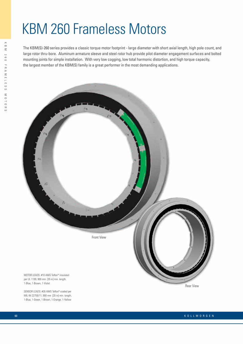
KBM 260 Frameless MotorsThe KBM(S)-260 series provides a classic torque motor footprint - large diameter with short axial length, high pole count, and large rotor thru-bore. Aluminum armature sleeve and steel rotor hub provide pilot diameter engagement surfaces and bolted mounting joints for simple installation. With very low cogging, low total harmonic distortion, and high torque capacity, the largest member of the KBM(S) family is a great performer in the most demanding applications.
KB
M
26
0
FR
AM
EL
ES
S
MO
TO
RS
60 K O L L M O R G E N
MOTOR LEADS: #10 AWG Teflon® insulatedper UL 1199, 900 mm [35 in] min. length,1-Blue, 1-Brown, 1-Violet
SENSOR LEADS: #26 AWG Teflon® coated per MIL-W-22759/11, 900 mm [35 in] min. length,1-Blue, 1-Green, 1-Brown, 1-Orange, 1-Yellow
Rear View
Front View
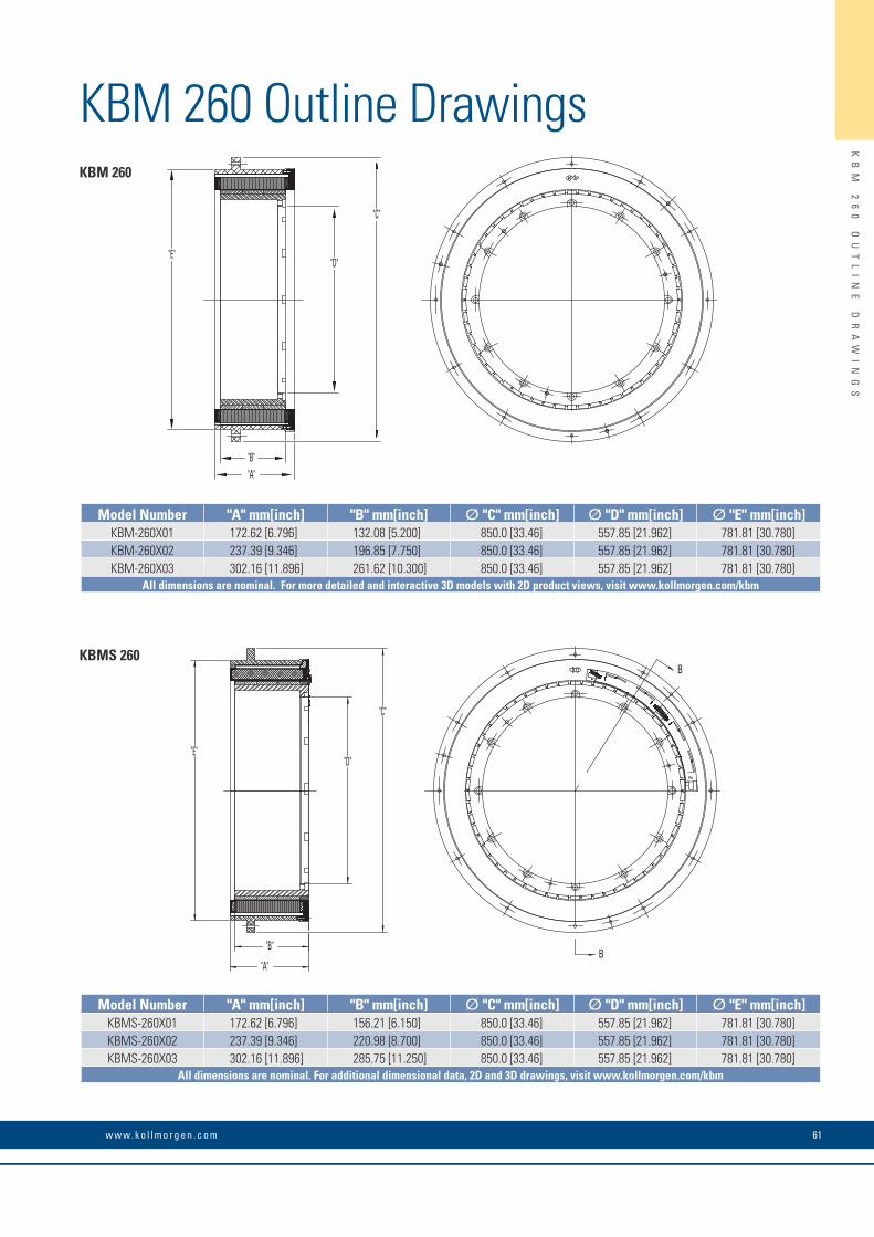
KBM 260 Outline Drawings
KB
M
26
0
OU
TL
IN
E
DR
AW
IN
GS
61w w w. k o l l m o r g e n . c o m
"E""D"
"C"
"A""B"
B
B"B"
"A"
"E""D"
"C"
KBM 260
KBMS 260
Model Number "A" mm[inch] "B" mm[inch] Ø "C" mm[inch] Ø "D" mm[inch] Ø "E" mm[inch]KBM-260X01 172.62 [6.796] 132.08 [5.200] 850.0 [33.46] 557.85 [21.962] 781.81 [30.780]KBM-260X02 237.39 [9.346] 196.85 [7.750] 850.0 [33.46] 557.85 [21.962] 781.81 [30.780]KBM-260X03 302.16 [11.896] 261.62 [10.300] 850.0 [33.46] 557.85 [21.962] 781.81 [30.780]
All dimensions are nominal. For more detailed and interactive 3D models with 2D product views, visit www.kollmorgen.com/kbm
Model Number "A" mm[inch] "B" mm[inch] Ø "C" mm[inch] Ø "D" mm[inch] Ø "E" mm[inch]KBMS-260X01 172.62 [6.796] 156.21 [6.150] 850.0 [33.46] 557.85 [21.962] 781.81 [30.780]KBMS-260X02 237.39 [9.346] 220.98 [8.700] 850.0 [33.46] 557.85 [21.962] 781.81 [30.780]KBMS-260X03 302.16 [11.896] 285.75 [11.250] 850.0 [33.46] 557.85 [21.962] 781.81 [30.780]
All dimensions are nominal. For additional dimensional data, 2D and 3D drawings, visit www.kollmorgen.com/kbm
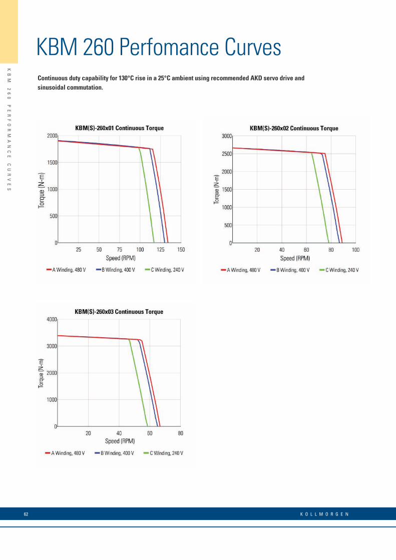
62 K O L L M O R G E N
KB
M
26
0
PE
RF
OR
MA
NC
E
CU
RV
ES
KBM 260 Perfomance CurvesContinuous duty capability for 130°C rise in a 25°C ambient using recommended AKD servo drive and sinusoidal commutation.
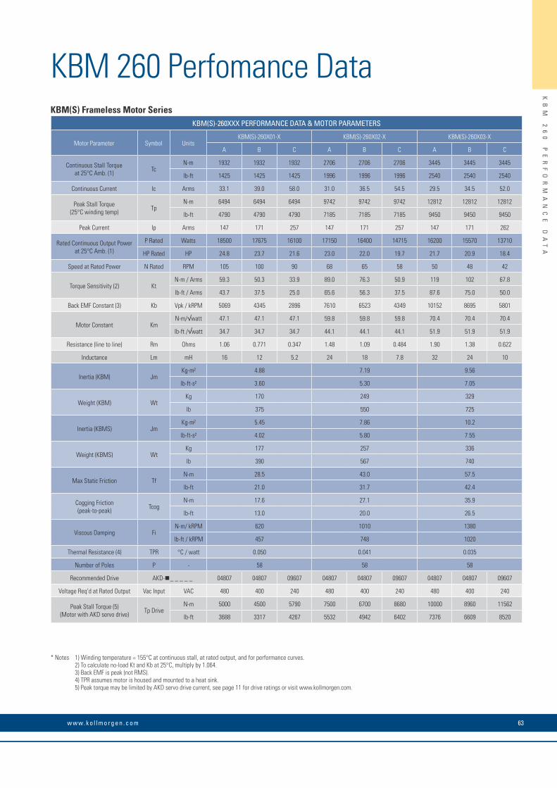
63w w w. k o l l m o r g e n . c o m
KB
M
26
0
PE
RF
OR
MA
NC
E
DA
TA
KBM 260 Perfomance Data
* Notes 1) Winding temperature = 155°C at continuous stall, at rated output, and for performance curves. 2) To calculate no-load Kt and Kb at 25°C, multiply by 1.064. 3) Back EMF is peak (not RMS). 4) TPR assumes motor is housed and mounted to a heat sink. 5) Peak torque may be limited by AKD servo drive current, see page 11 for drive ratings or visit www.kollmorgen.com.
KBM(S) Frameless Motor SeriesKBM(S)-260XXX PERFORMANCE DATA & MOTOR PARAMETERS
Motor Parameter Symbol UnitsKBM(S)-260X01-X KBM(S)-260X02-X KBM(S)-260X03-X
A B C A B C A B C
Continuous Stall Torque at 25°C Amb. (1) Tc
N-m 1932 1932 1932 2706 2706 2706 3445 3445 3445
lb-ft 1425 1425 1425 1996 1996 1996 2540 2540 2540
Continuous Current Ic Arms 33.1 39.0 58.0 31.0 36.5 54.5 29.5 34.5 52.0
Peak Stall Torque (25°C winding temp) Tp
N-m 6494 6494 6494 9742 9742 9742 12812 12812 12812
lb-ft 4790 4790 4790 7185 7185 7185 9450 9450 9450
Peak Current Ip Arms 147 171 257 147 171 257 147 171 262
Rated Continuous Output Power at 25°C Amb. (1)
P Rated Watts 18500 17675 16100 17150 16400 14715 16200 15570 13710
HP Rated HP 24.8 23.7 21.6 23.0 22.0 19.7 21.7 20.9 18.4
Speed at Rated Power N Rated RPM 105 100 90 68 65 58 50 48 42
Torque Sensitivity (2) KtN-m / Arms 59.3 50.3 33.9 89.0 76.3 50.9 119 102 67.8
lb-ft / Arms 43.7 37.5 25.0 65.6 56.3 37.5 87.6 75.0 50.0
Back EMF Constant (3) Kb Vpk / kRPM 5069 4345 2896 7610 6523 4349 10152 8695 5801
Motor Constant KmN-m/√watt 47.1 47.1 47.1 59.8 59.8 59.8 70.4 70.4 70.4
lb-ft /√watt 34.7 34.7 34.7 44.1 44.1 44.1 51.9 51.9 51.9
Resistance (line to line) Rm Ohms 1.06 0.771 0.347 1.48 1.09 0.484 1.90 1.38 0.622
Inductance Lm mH 16 12 5.2 24 18 7.8 32 24 10
Inertia (KBM) JmKg-m² 4.88 7.19 9.56
lb-ft-s² 3.60 5.30 7.05
Weight (KBM) WtKg 170 249 329
lb 375 550 725
Inertia (KBMS) JmKg-m² 5.45 7.86 10.2
lb-ft-s² 4.02 5.80 7.55
Weight (KBMS) WtKg 177 257 336
lb 390 567 740
Max Static Friction TfN-m 28.5 43.0 57.5
lb-ft 21.0 31.7 42.4
Cogging Friction (peak-to-peak) Tcog
N-m 17.6 27.1 35.9
lb-ft 13.0 20.0 26.5
Viscous Damping FiN-m/ kRPM 620 1010 1380
lb-ft / kRPM 457 748 1020
Thermal Resistance (4) TPR °C / watt 0.050 0.041 0.035
Number of Poles P - 58 58 58
Recommended Drive AKD- _ _ _ _ _ 04807 04807 09607 04807 04807 09607 04807 04807 09607
Voltage Req’d at Rated Output Vac Input VAC 480 400 240 480 400 240 480 400 240
Peak Stall Torque (5) (Motor with AKD servo drive) Tp Drive
N-m 5000 4500 5790 7500 6700 8680 10000 8960 11562
lb-ft 3688 3317 4267 5532 4942 6402 7376 6609 8520
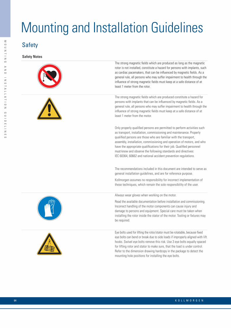
K O L L M O R G E N 64
MO
UN
TI
NG
A
ND
I
NS
TA
LL
AT
IO
N
GU
ID
EL
IN
ES
Mounting and Installation GuidelinesSafety
Safety Notes
The strong magnetic fields which are produced as long as the magnetic rotor is not installed, constitute a hazard for persons with implants, such as cardiac pacemakers, that can be influenced by magnetic fields. As a general rule, all persons who may suffer impairment to health through the influence of strong magnetic fields must keep at a safe distance of at least 1 meter from the rotor.
The strong magnetic fields which are produced constitute a hazard for persons with implants that can be influenced by magnetic fields. As a general rule, all persons who may suffer impairment to health through the influence of strong magnetic fields must keep at a safe distance of at least 1 meter from the motor.
Only properly qualified persons are permitted to perform activities such as transport, installation, commissioning and maintenance. Properly qualified persons are those who are familiar with the transport, assembly, installation, commissioning and operation of motors, and who have the appropriate qualifications for their job. Qualified personnel must know and observe the following standards and directives: IEC 60364, 60662 and national accident prevention regulations.
The recommendations included in this document are intended to serve as general installation guidelines, and are for reference purpose.
Kollmorgen assumes no responsibility for incorrect implementation of these techniques, which remain the sole responsibility of the user.
Always wear gloves when working on the motor.
Read the available documentation before installation and commissioning. Incorrect handling of the motor components can cause injury and damage to persons and equipment. Special care must be taken when installing the rotor inside the stator of the motor. Tooling or fixtures may be required.
Eye bolts used for lifting the rotor/stator must be rotatable, because fixed eye bolts can bend or break due to side loads if improperly aligned with lift hooks. Swivel eye bolts remove this risk. Use 3 eye bolts equally spaced for lifting rotor and stator to make sure, that the load is under control. Refer to the dimension drawing hardcopy in the package to detect the mounting hole positions for installing the eye bolts.
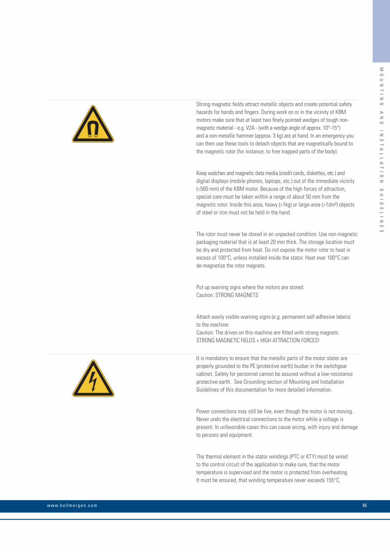
65w w w. k o l l m o r g e n . c o m
MO
UN
TI
NG
A
ND
I
NS
TA
LL
AT
IO
N
GU
ID
EL
IN
ES
Strong magnetic fields attract metallic objects and create potential safety hazards for hands and fingers. During work on or in the vicinity of KBM motors make sure that at least two finely pointed wedges of tough non-magnetic material - e.g. V2A - (with a wedge angle of approx. 10°-15°) and a non-metallic hammer (approx. 3 kg) are at hand. In an emergency you can then use these tools to detach objects that are magnetically bound to the magnetic rotor (for instance, to free trapped parts of the body).
Keep watches and magnetic data media (credit cards, diskettes, etc.) and digital displays (mobile phones, laptops, etc.) out of the immediate vicinity (<500 mm) of the KBM motor. Because of the high forces of attraction, special care must be taken within a range of about 50 mm from the magnetic rotor. Inside this area, heavy (>1kg) or large-area (>1dm²) objects of steel or iron must not be held in the hand.
The rotor must never be stored in an unpacked condition. Use non-magnetic packaging material that is at least 20 mm thick. The storage location must be dry and protected from heat. Do not expose the motor rotor to heat in excess of 100°C, unless installed inside the stator. Heat over 100°C can de-magnetize the rotor magnets.
Put up warning signs where the motors are stored: Caution: STRONG MAGNETS
Attach easily visible warning signs (e.g. permanent self-adhesive labels) to the machine: Caution: The drives on this machine are fitted with strong magnets. STRONG MAGNETIC FIELDS + HIGH ATTRACTION FORCES!
It is mandatory to ensure that the metallic parts of the motor stator are properly grounded to the PE (protective earth) busbar in the switchgear cabinet. Safety for personnel cannot be assured without a low-resistance protective earth. See Grounding section of Mounting and Installation Guidelines of this documentation for more detailed information.
Power connections may still be live, even though the motor is not moving. Never undo the electrical connections to the motor while a voltage is present. In unfavorable cases this can cause arcing, with injury and damage to persons and equipment.
The thermal element in the stator windings (PTC or KTY) must be wired to the control circuit of the application to make sure, that the motor temperature is supervised and the motor is protected from overheating. It must be ensured, that winding temperature never exceeds 155°C.

K O L L M O R G E N 66
MO
UN
TI
NG
A
ND
I
NS
TA
LL
AT
IO
N
GU
ID
EL
IN
ES
Use as Directed
• The KBM series of permanent magnet frameless motors is designed especially for motion applications for industrial robots, machine tools, textile, packing machinery and similar machines with high requirements for dynamic positioning and servo movement.• The user is only permitted to operate the motors under the ambient conditions which are defined in this documentation.• The series of motors is exclusively intended to be driven by servo amplifiers under speed and / or torque control.• The motors are installed as components in electrical apparatus or machines and can only be commissioned and put into operation as integral components of such apparatus or machines.• The thermal resistor which is integrated in the motor windings must be supervised and evaluated.• The conformity of the KBM motor to the standards mentioned in the EC Declaration of Conformity is only guaranteed when installed in accordance with the Mounting & Installation Guidelines in this documentation. The end user assumes responsibility for machine conformity.• The KBM motor only use UL/UR approved materials and is designed in full compliance with agency creepage and clearance dimensional guidelines. The End User assumes responsibility for machine conformity. Kollmorgen delivers all required information for supporting machine UL
Prohibited Use
The use of the motors in the following environments is prohibited:• potentially explosive areas• environments with corrosive and/or electrically conductive acids, alkaline solutions, oils, vapours, dusts• vacuum• directly on supply networks
Commissioning the motor is prohibited if the machine in which it was installed • does not meet the requirements of the EC Machinery Directive• does not comply with the EMC Directive• does not comply with the Low Voltage Directive
Package delivered The weight of the package which you receive depends on the number of parts inside. The weight given below always means the maximum possible weight for the package.
Motor Type
KBM10 to 43
KBM45
KBM57
KBM60
KBM79
KBM88
KBM118
KBM163
KBM260
25
60
25
60
80
135
110
190
350
Reinforced fiberboard box with inner padding, hand lifted
Wooden crate with inner padding, lift with hoist
Reinforced fiberboard box with inner padding, hand lifted
Wooden crate with inner padding, lift with hoist
Wooden crate with inner padding, lift with hoist
Wooden create with inner padding and pallet base, lift with fork truck
Wooden crate with inner padding, lift with hoist
Wooden crate with inner padding and pallet base, lift with fork truck
Wooden crate with inner padding and pallet base, lift with fork truck
Max Shipping Container Weight [kg]Packaging
Mounting and Installation Guidelines
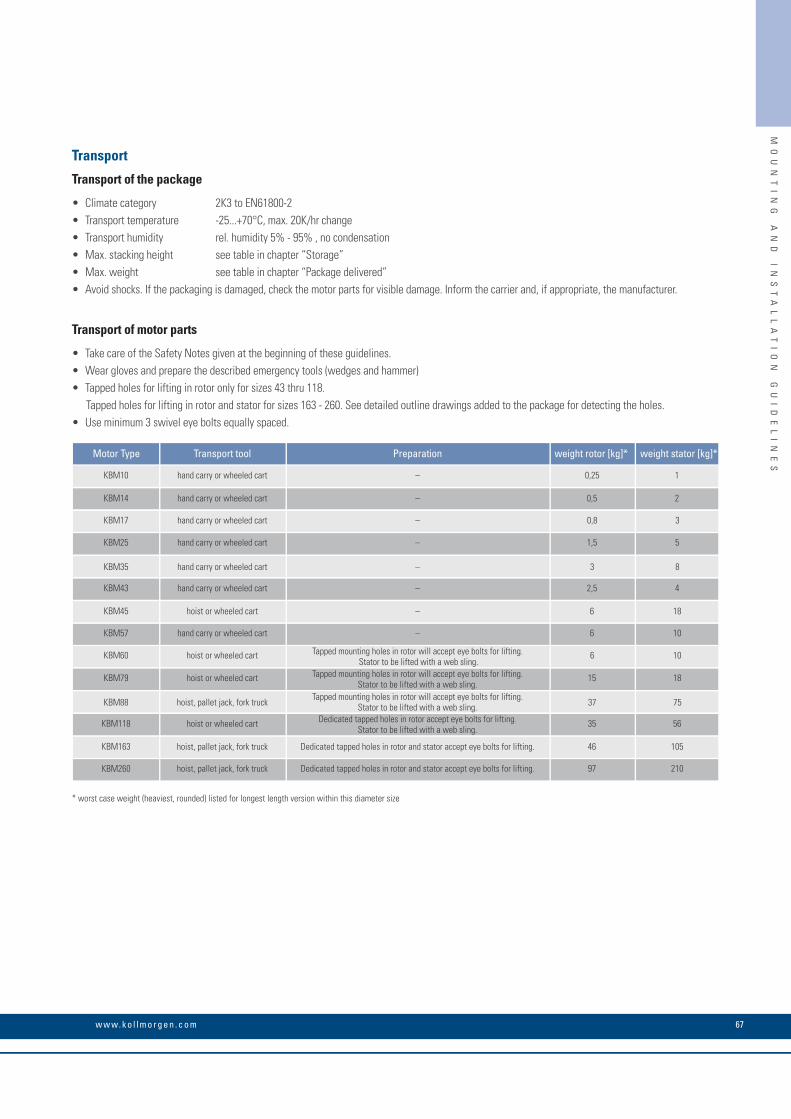
67w w w. k o l l m o r g e n . c o m
MO
UN
TI
NG
A
ND
I
NS
TA
LL
AT
IO
N
GU
ID
EL
IN
ES
Transport
Transport of the package
• Climate category 2K3 to EN61800-2 • Transport temperature -25...+70°C, max. 20K/hr change• Transport humidity rel. humidity 5% - 95% , no condensation• Max. stacking height see table in chapter “Storage” • Max. weight see table in chapter “Package delivered”• Avoid shocks. If the packaging is damaged, check the motor parts for visible damage. Inform the carrier and, if appropriate, the manufacturer.
Transport of motor parts
• Take care of the Safety Notes given at the beginning of these guidelines.• Wear gloves and prepare the described emergency tools (wedges and hammer)• Tapped holes for lifting in rotor only for sizes 43 thru 118. Tapped holes for lifting in rotor and stator for sizes 163 - 260. See detailed outline drawings added to the package for detecting the holes.• Use minimum 3 swivel eye bolts equally spaced.
* worst case weight (heaviest, rounded) listed for longest length version within this diameter size
Motor Type
KBM10
KBM14
KBM17
KBM60
0,25 1
0,5 2
0,8 3
6 10
hand carry or wheeled cart –
hand carry or wheeled cart –
hand carry or wheeled cart –
KBM25
KBM35
KBM43
KBM45
KBM57
1,5 5
3 8
2,5 4
6 18
6 10
hand carry or wheeled cart –
hand carry or wheeled cart –
hand carry or wheeled cart –
hoist or wheeled cart –
hand carry or wheeled cart –
KBM79
KBM88
KBM118
KBM163
KBM260
15 18
37 75
35 56
46 105
97 210
hoist or wheeled cart Tapped mounting holes in rotor will accept eye bolts for lifting. Stator to be lifted with a web sling.
hoist, pallet jack, fork truck Tapped mounting holes in rotor will accept eye bolts for lifting. Stator to be lifted with a web sling.
hoist or wheeled cart Dedicated tapped holes in rotor accept eye bolts for lifting. Stator to be lifted with a web sling.
hoist, pallet jack, fork truck Dedicated tapped holes in rotor and stator accept eye bolts for lifting.
hoist, pallet jack, fork truck Dedicated tapped holes in rotor and stator accept eye bolts for lifting.
hoist or wheeled cart Tapped mounting holes in rotor will accept eye bolts for lifting. Stator to be lifted with a web sling.
Preparation weight rotor [kg]* weight stator [kg]*Transport tool
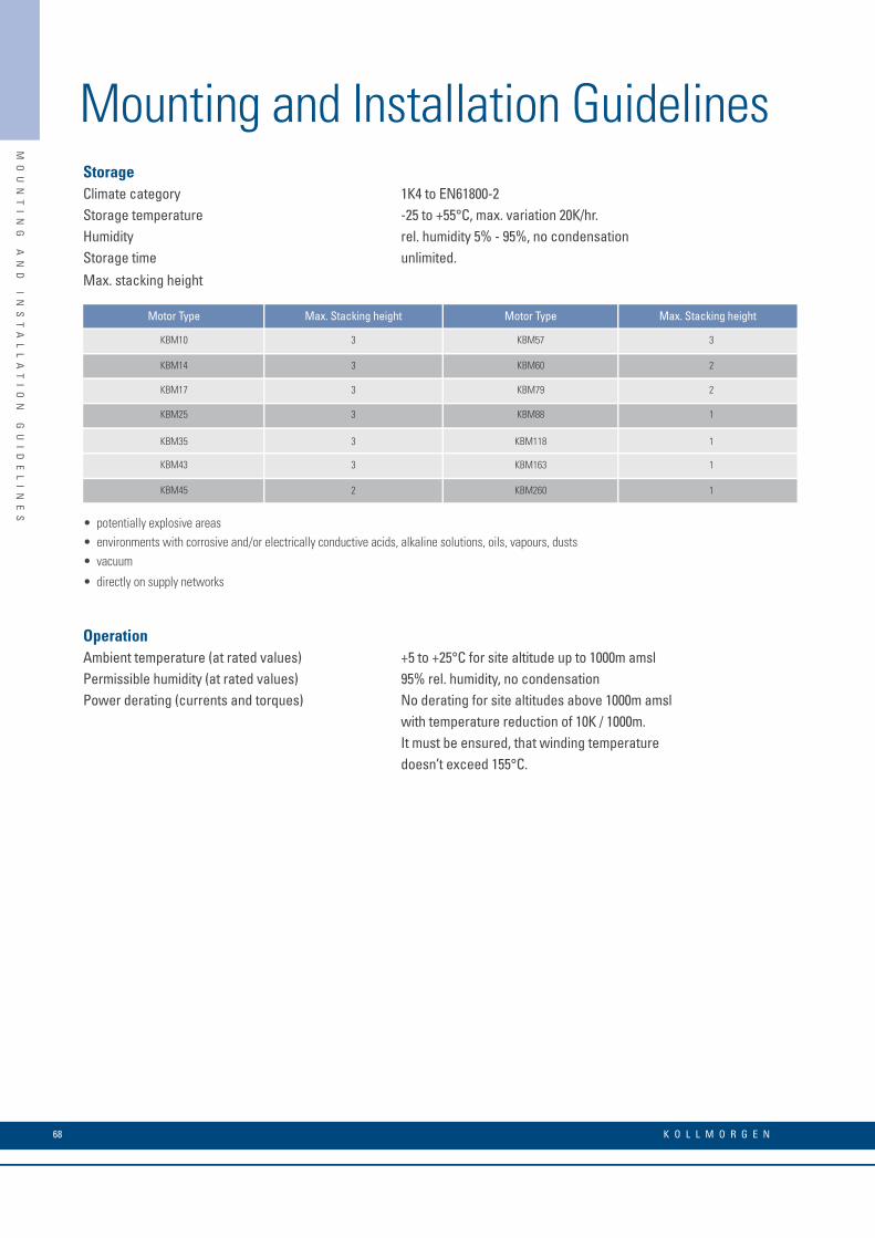
K O L L M O R G E N 68
MO
UN
TI
NG
A
ND
I
NS
TA
LL
AT
IO
N
GU
ID
EL
IN
ES
StorageClimate category 1K4 to EN61800-2Storage temperature -25 to +55°C, max. variation 20K/hr.Humidity rel. humidity 5% - 95%, no condensationStorage time unlimited. Max. stacking height
• potentially explosive areas• environments with corrosive and/or electrically conductive acids, alkaline solutions, oils, vapours, dusts• vacuum
• directly on supply networks
OperationAmbient temperature (at rated values) +5 to +25°C for site altitude up to 1000m amslPermissible humidity (at rated values) 95% rel. humidity, no condensationPower derating (currents and torques) No derating for site altitudes above 1000m amsl with temperature reduction of 10K / 1000m. It must be ensured, that winding temperature doesn’t exceed 155°C.
Motor Type
KBM10
KBM14
KBM17
KBM25
KBM35
KBM43
KBM45
3
2
2
1
1
1
1
3 KBM57
3 KBM60
3 KBM79
3 KBM88
3 KBM118
3 KBM163
2 KBM260
Max. Stacking heightMax. Stacking height Motor Type
Mounting and Installation Guidelines
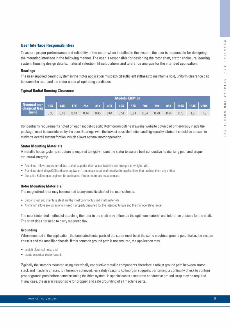
69w w w. k o l l m o r g e n . c o m
MO
UN
TI
NG
A
ND
I
NS
TA
LL
AT
IO
N
GU
ID
EL
IN
ES
Models KBM(S)
Nominal me-chanical Gap
[mm]
10X 14X 17X 25X 35X 43X 45X 57X 60X 79X 88X 118X 163X 260X
0.38 0.43 0.43 0.44 0.45 0.64 0.51 0.64 0.64 0.70 0.64 0.76 1.9 1.9
User Interface Responsibilities
To assure proper performance and reliability of the motor when installed in the system, the user is responsible for designing the mounting interface in the following manner. The user is responsible for designing the rotor shaft, stator enclosure, bearing system, housing design details, material selection, fit calculations and tolerance analysis for the intended application.
BearingsThe user-supplied bearing system in the motor application must exhibit sufficient stiffness to maintain a rigid, uniform clearance gap between the rotor and the stator under all operating conditions.
Typical Radial Running Clearance
Concentricity requirements noted on each model-specific Kollmorgen outline drawing (website download or hardcopy inside the package) must be considered by the user. Bearings with the lowest possible friction and high quality lubricant should be chosen to minimize overall system friction, which allows optimal motor operation.
Stator Mounting MaterialsA metallic housing/clamp structure is required to rigidly mount the stator to assure best conductive heatsinking path and proper structural integrity:
• Aluminum alloys are preferred due to their superior thermal conductivity and strength-to-weight ratio.• Stainless steeI alloys (300 series or equivalent) are an acceptable alternative for applications that are less thermally criticaI. • Consult a Kollmorgen engineer for assistance if other materials must be used.
Rotor Mounting MaterialsThe magnetized rotor may be mounted to any metallic shaft of the user’s choice.
• Carbon steel and stainless steel are the most commonly used shaft materials• Aluminum alloys are occasionally used if properly designed for the intended torque and thermal operating range.
The user’s intended method of attaching the rotor to the shaft may influence the optimum material and tolerance choices for the shaft. The shaft does not need to carry magnetic flux.
GroundingWhen mounted in the application, the Iaminated metal parts of the stator must be at the same electrical ground potential as the system chassis and the amplifier chassis. If this common ground path is not ensured, the application may
• exhibit electrical noise and• create electrical shock hazard.
Typically the stator is mounted using electrically conductive metallic components, therefore a robust ground path between stator stack and machine chassis is inherently achieved. For safety reasons Kollmorgen suggests performing a continuity check to confirm proper ground path before commissioning the drive system. ln special cases a separate conductive ground strap may be required. ln any case, the user is responsible for propper and safe grounding of all machine parts.
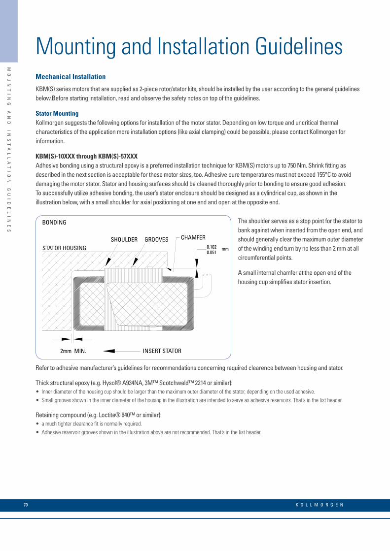
Mechanical Installation
KBM(S) series motors that are supplied as 2-piece rotor/stator kits, should be installed by the user according to the general guidelines below.Before starting installation, read and observe the safety notes on top of the guidelines.
Stator MountingKollmorgen suggests the following options for installation of the motor stator. Depending on low torque and uncritical thermal characteristics of the application more installation options (like axial clamping) could be possible, please contact Kollmorgen for information.
KBM(S)-10XXX through KBM(S)-57XXXAdhesive bonding using a structural epoxy is a preferred installation technique for KBM(S) motors up to 750 Nm. Shrink fitting as described in the next section is acceptable for these motor sizes, too. Adhesive cure temperatures must not exceed 155°C to avoid damaging the motor stator. Stator and housing surfaces should be cleaned thoroughly prior to bonding to ensure good adhesion. To successfully utilize adhesive bonding, the user’s stator enclosure should be designed as a cylindrical cup, as shown in the illustration below, with a small shoulder for axial positioning at one end and open at the opposite end.
Refer to adhesive manufacturer’s guidelines for recommendations concerning required clearence between housing and stator.
Thick structural epoxy (e.g. Hysol® A934NA, 3M™ Scotchweld™ 2214 or similar): • Inner diameter of the housing cup should be larger than the maximum outer diameter of the stator, depending on the used adhesive. • Small grooves shown in the inner diameter of the housing in the illustration are intended to serve as adhesive reservoirs. That’s in the list header.
Retaining compound (e.g. Loctite® 640™ or similar): • a much tighter clearance fit is normally required. • Adhesive reservoir grooves shown in the illustration above are not recommended. That’s in the list header.
Mounting and Installation Guidelines
SHOULDER GROOVES
INSERT STATOR
STATOR HOUSING
BONDING
CHAMFER
.
2mm MIN.
.
0.1020.051
mm
The shoulder serves as a stop point for the stator to bank against when inserted from the open end, and should generally clear the maximum outer diameter of the winding end turn by no less than 2 mm at all circumferential points.
A small internal chamfer at the open end of the housing cup simplifies stator insertion.
K O L L M O R G E N 70
MO
UN
TI
NG
A
ND
I
NS
TA
LL
AT
IO
N
GU
ID
EL
IN
ES
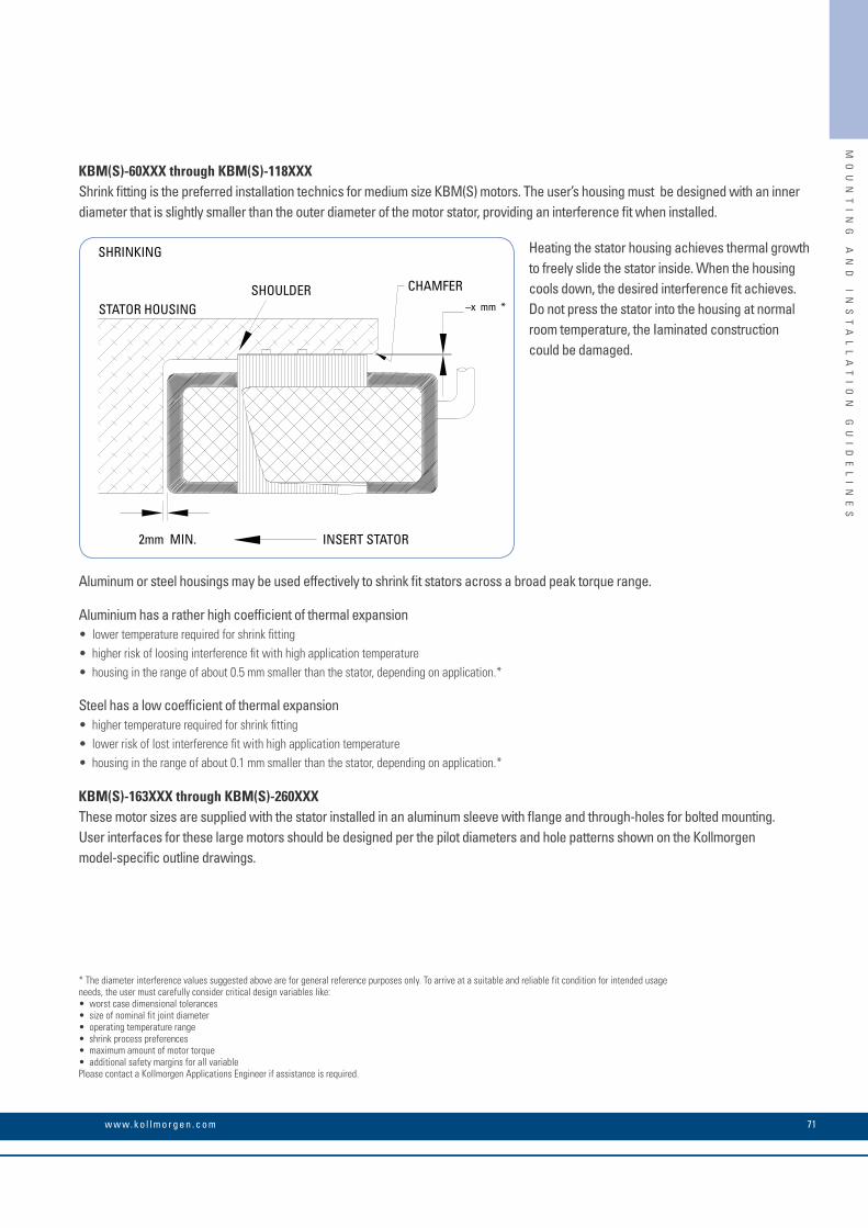
Heating the stator housing achieves thermal growth to freely slide the stator inside. When the housing cools down, the desired interference fit achieves. Do not press the stator into the housing at normal room temperature, the Iaminated construction could be damaged.
SHOULDER
INSERT STATOR
STATOR HOUSING
SHRINKING
CHAMFER
.
2mm MIN.
.
–x mm *
71w w w. k o l l m o r g e n . c o m
MO
UN
TI
NG
A
ND
I
NS
TA
LL
AT
IO
N
GU
ID
EL
IN
ES
KBM(S)-60XXX through KBM(S)-118XXXShrink fitting is the preferred installation technics for medium size KBM(S) motors. The user’s housing must be designed with an inner diameter that is slightly smaller than the outer diameter of the motor stator, providing an interference fit when installed.
Aluminum or steel housings may be used effectively to shrink fit stators across a broad peak torque range.
Aluminium has a rather high coefficient of thermal expansion • lower temperature required for shrink fitting • higher risk of loosing interference fit with high application temperature • housing in the range of about 0.5 mm smaller than the stator, depending on application.*
Steel has a low coefficient of thermal expansion • higher temperature required for shrink fitting • lower risk of lost interference fit with high application temperature • housing in the range of about 0.1 mm smaller than the stator, depending on application.*
KBM(S)-163XXX through KBM(S)-260XXXThese motor sizes are supplied with the stator installed in an aluminum sleeve with flange and through-holes for bolted mounting. User interfaces for these large motors should be designed per the pilot diameters and hole patterns shown on the Kollmorgen model-specific outline drawings.
* The diameter interference values suggested above are for general reference purposes only. To arrive at a suitable and reliable fit condition for intended usage needs, the user must carefully consider critical design variables like: • worst case dimensional tolerances • size of nominal fit joint diameter • operating temperature range • maximum amount of motor torque • additional safety margins for all variable Please contact a Kollmorgen Applications Engineer if assistance is required.
• shrink process preferences
Rotor Mounting to Shaft Kollmorgen’s KBM(S) series utilize high-performance rare earth magnets. Use extreme caution when handling or transporting to avoid injury and product damage. The attractive forces between magnetized rotors and nearby metallic objects can be extremely powerful. It’s highly recommended that you read and observe the safety notes on top of the guidelines.
Axial Alignment Control Kollmorgen’s model-specific outline drawings note axial alignment that must be maintained between rotor and stator when mounted to ensure proper motor performance. Machined shoulders on the shaft or grooves for removable retaining rings are common ways of controlling rotor installation position. Maximum diameter of retaining rings or shaft shoulders should be kept below the rotor diameter where magnets are bonded to the steel hub.
Bonding For applications where peak torque does not exceed 750 Nm, rotors can be bonded to carbon steel or stainless steel shafts.
• Retaining compounds, such as Loctite 640 or other similar adhesives, usually require smooth continuous interface diameters and tight fit tolerances. • Structural epoxies generally require slightly larger fit clearance to allow a thicker bond line. Epoxies often benefit from grooves in the shaft/rotor interface that function as adhesive reservoirs and may be enhanced by textured machined surfaces via knurling or grit blasting.
Always clean the bond joint surfaces thoroughly to ensure good adhesion. To avoid partial demagnetization of the rotor, do not cure rotor/shaft bond joints at temperatures >100°. Consult adhesive manufacturer for proper bond line thickness, fit tolerances, process details and curing guidelines. A highly flexible adhesive with broad thermal properties may be required. Contact a Kollmorgen engineer if more information is required on this topic.
Axial Clamping If the user’s shaft is designed with a machined shoulder that the rotor can rigidly bank against, the rotor may be axially clamped in place using a Iocknut for applications up to 400 Nm peak torque, although this estimate may vary greatly depending upon size and type of nut used. This technique allows the rotor to be installed and removed from the shaft repeatedly, but requires a portion of the shaft to be threaded.
Bolting KBM(S)-43XXX and larger sizes are provided with hole patterns in the rotor hub to facilitate bolted mounting. User shaft interface should be designed per the diameter, length, axial position and hole pattern noted on the Kollmorgen model specific outline drawing.
Mounting and Installation Guidelines
K O L L M O R G E N 72
MO
UN
TI
NG
A
ND
I
NS
TA
LL
AT
IO
N
GU
ID
EL
IN
ES
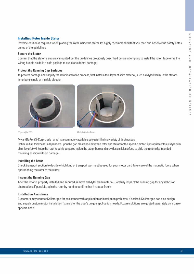
73w w w. k o l l m o r g e n . c o m
lnstalling Rotor Inside Stator Extreme caution is required when placing the rotor inside the stator. It’s highly recommended that you read and observe the safety notes on top of the guidelines.
Secure the StatorConfirm that the stator is securely mounted per the guidelines previously described before attempting to install the rotor. Tape or tie the wiring bundle aside in a safe position to avoid accidental damage.
Protect the Running Gap SurfacesTo prevent damage and simplify the rotor installation process, first install a thin layer of shim material, such as Mylar® film, in the stator’s inner bore (single or multiple pieces).
Mylar (DuPont® Corp. trade name) is a commonly available polyesterfilm in a variety of thicknesses. Optimum film thickness is dependent upon the gap clearance between rotor and stator for the specific motor. Appropriately thick Mylarfilm shim layer(s) will keep the rotor roughly centered inside the stator bore and provides a slick surface to slide the rotor to its intended mounting position without damage.
lnstalling the RotorCheck transport section to decide which kind of transport tool must beused for your motor part. Take care of the magnetic force when approaching the rotor to the stator.
lnspect the Running GapAfter the rotor is properly installed and secured, remove all Mylar shim material. Carefully inspect the running gap for any debris or obstructions. lf possible, spin the rotor by hand to confirm that it rotates freely.
Installation AssistanceCustomers may contact Kollmorgen for assistance with application or installation problems. lf desired, Kollmorgen can also design and supply custom motor installation fixtures for the user’s unique application needs. Fixture solutions are quoted separately on a case-specific basis.
Single Mylar Shim Multiple Mylar Shims
MO
UN
TI
NG
A
ND
I
NS
TA
LL
AT
IO
N
GU
ID
EL
IN
ES
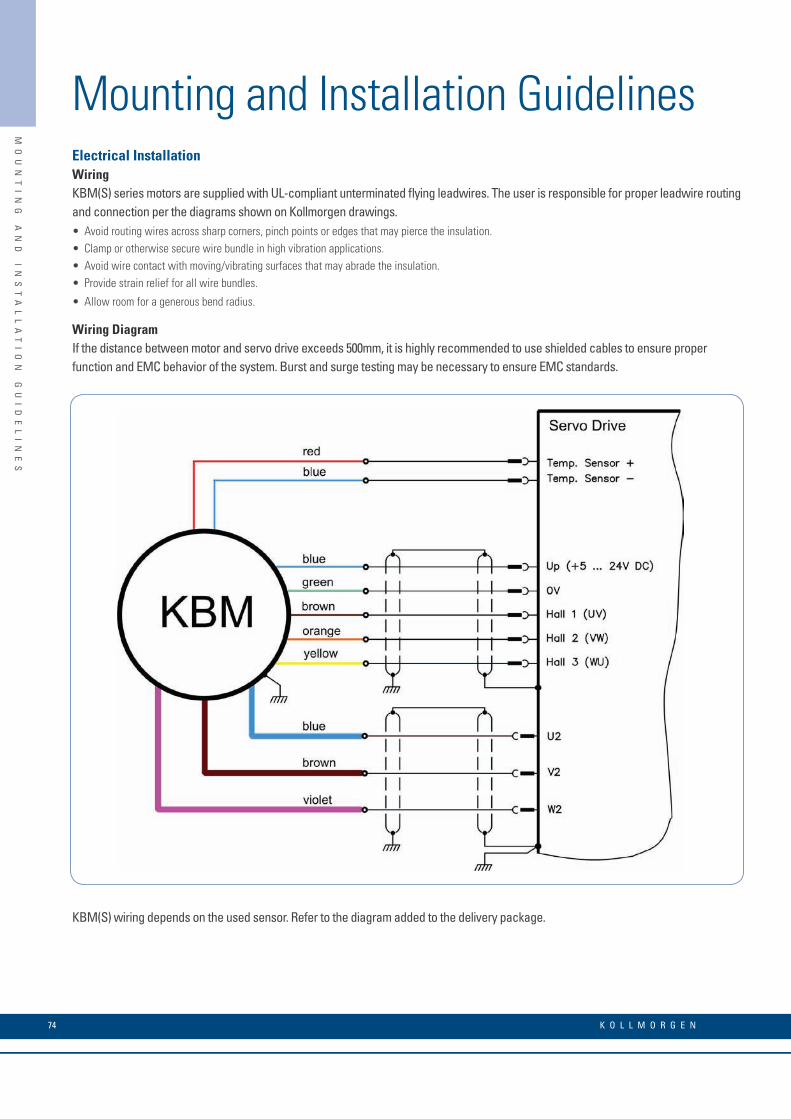
Mounting and Installation Guidelines
K O L L M O R G E N 74
• Avoid routing wires across sharp corners, pinch points or edges that may pierce the insulation. • Clamp or otherwise secure wire bundle in high vibration applications. • Avoid wire contact with moving/vibrating surfaces that may abrade the insulation. • Provide strain relief for all wire bundles.
• Allow room for a generous bend radius.
Electrical InstallationWiring KBM(S) series motors are supplied with UL-compliant unterminated flying leadwires. The user is responsible for proper leadwire routing and connection per the diagrams shown on Kollmorgen drawings.
Wiring Diagram If the distance between motor and servo drive exceeds 500mm, it is highly recommended to use shielded cables to ensure proper function and EMC behavior of the system. Burst and surge testing may be necessary to ensure EMC standards.
KBM(S) wiring depends on the used sensor. Refer to the diagram added to the delivery package.
MO
UN
TI
NG
A
ND
I
NS
TA
LL
AT
IO
N
GU
ID
EL
IN
ES

75w w w. k o l l m o r g e n . c o m
MO
DE
L
NO
ME
NC
LA
TU
RE
KBM Frameless Motor Nomenclature
Sequential Number for Available Modifications (See page 78)
KBM(S) - 25 H 01 - A XXProduct Family
Stack Length Specifier01 = 1
02 = 2
03 = 3
04 = 4
(A, B, C, etc...)
Winding OptionsMotor Frame Size (Armature I.D.)10 57
14 60
17 79
25 88
35 118
43 163
45 260
Insulation Ratings
KBM Series = Frameless motor
KBMS = Frameless motor with sensors
Available KBM(S) ModificationsThe following modifications allow our customers to optimize the base model configuration to meet the unique challenges of their application needs. Please consult Kollmorgen Customer Support for information, pricing, and feasibility of desired modifications. Engineering and soft tooling fees may be required. Additional lead time required.
Speed/Torque Changes Generally Available Capability• Winding Gages #00 – #48 AWG (includes lead wire change)
• Stack Lengths Available 6.35 mm (0.25 in) to 610 mm (24 in) (Rotor length, including magnets, will increase or decrease proportionally)
• Pole Count 6 to 64 Poles
• Magnet Materials Neodymium-Iron-Boron (base model) Samarium Cobalt
Durability/Harsh Environment• Rotor Hub Material Bare Cold-Rolled Steel (base model) Corrosion-resistant Stainless Alloy
• Stator Sleeve Material Bare Aluminum (select base models) Stainless or Carbon Steel
• Armature Potting Encapsulation (base model) Varnish Hi-Temp Encapsulation (200°C)
• Corrosion Protection Dri-Touch Corrosion Inhibitor (base model) Nickel Plating, Passivation, Anodizing Epoxy Paint
Installation Features• Rotor Hub Geometry Round, hollow, flanged, keyway, flat Thru bores from 5 mm to 600 mm
• Mounting Bolt hole diameter and circumferential pattern (customer specified)
• Lead Length 400 mm (15.75 in) min (base model) 150 mm to 1200+ mm (customer specified)
• Lead Colors Blue / Brown / Violet (base model) Other colors to be specified by customer
• Thermal Sensor Thermistor (base model) Thermostat, RTD, Thermocouple Omit thermal sensor
• Connector(s) None-Flying leads (base model) Connector(s) specified by customer
H = High voltage insulation (>240 Vac), S = Standard insulation (≤240 Vac)
© 2010 Kollmorgen Corporation. All rights reserved. KM_BR_00073_RevA_UK Specifications are subject to change without notice. It is the responsibility of the product user to determine the suitability of this product for a specific application. All trademarks are the property of their respective owners.
About Kollmorgen
Kollmorgen is a leading provider of motion systems and components for machine builders. Through world-class knowledge in motion, industry-leading quality and deep expertise in linking and integrating standard and custom products, Kollmorgen delivers breakthrough solutions that are unmatched in performance, reliability and ease-of-use, giving machine builders an irrefutable marketplace advantage.
For assistance with your application needs visit www.kollmorgen.com for a global contact list.
Application Centers
Global Design & Manufacturing
Global Manufacturing
San JoseSanta Barbara
Tijuana
Radford
Fond du LacMarengo
Lausanne
Ratingen
StockholmSäro
BrnoMilan
Mumbai
Kluang
Hong Kong
Shanghai
BeijingTianjin
NagoyaTokyo
KOLLMORGEN Europe GmbH Pempelfurtstraße 140880 RatingenGermanyPhone: +49 (0) 2102 9394 0 Fax: +49 (0) 2102 9394 3155
Seoul
Sao Paulo