kitty: keyboard independent touch typing in...
TRANSCRIPT

KITTY: Keyboard Independent Touch Typing in VR
Carsten MehringDept. of Mechanical and Aerospace Eng.
University of California, Irvine, CA 92697{cmehring}@uci.edu
Falko Kuester, Kunal Deep Singh and Michelle ChenDept. of Electrical Eng. and Computer Science
University of California, Irvine, CA 92697{fkuester,singhk,mchen}@uci.edu
Abstract
A new hand- or finger-mounted data input device is pre-sented, using traditional touch-typing skills as method of (al-phabetic) character input thus providing an ultra-portablesolution for “quiet” data input into portable computer sys-tems. The presented keyboard independent touch-typing de-vice (KITTY) offers high data input rates and a virtually zerolearning curve for new users.
1 Motivation
With recent advances in portable computing and in par-ticular the design of pocket PCs [13] and eye-glass displays[14], the development of new augmented reality (AR) envi-ronments has been made possible. However, one of the cur-rent shortcomings in these AR systems is the lack of intuitiveinput devices that provide users with complete control overtheir workspace. In particular in environments where voiceinput is undesirable or infeasible, touch-typing capabilitieshave to be available to allow for intuitive access to possiblycomplex data.
2 Introduction
The size, layout and weight of traditional keyboards makethem poor candidates for use in mobile AR applications.In particular, if integration with mobile computing devices,such as personal digital assistants (PDAs) or pocket personalcomputers (PocketPCs) is desired, a new generation of natu-ral handheld input devices is required.
Today’s mobile computing devices frequently include aphysical or digital miniature keyboard, that may be inte-grated with the device, worn on the user’s wrist or simplybe part of the display area. Unfortunately, these keyboardsgenerally require the use of both hands, one holding the de-vice and the other for finger-based or stylus-based data input.The selection of individual keys on a hand held display-basedkeyboard, for example, is a rather inefficient process and re-quires the user to look at the keyboard devise. Handwriting
Figure 1. Prototype glove system illustrating initial contact
placement.
recognition can increase input rates after extensive trainingbut is still very limiting. This performance gap is problem-atic if the portable computing devices are to be operated atthe level suitable for today’s computational platforms.
Other devices for data input into portable computingunits, include chording devices, such as a hand-mounted key-pads that require the user to press different key combinationsto generate the characters found on a standard keyboard. Fur-ther alternatives include microphones in combination withvoice recognition software. The former input devices typi-cally do not meet the data input rates desired for full-scaleinteraction and typically require the user to learn a chord-ing/coding language particular to the specific device. Onthe other hand, privacy concerns or ambient noise frequentlylimit the use of voice recognition devices. Possible scenariosinclude input of confidential or sensitive data via voice recog-nition in conference settings, meetings, or crowded publicplaces, such as airports.
3 Related Work
With a demand for decreased keyboard size and increasedportability, while maintaining the traditional keyboard lay-out, new device concepts are required. A first attempt was

the development of foldable keyboards that allowed users tocarry familiar input devices with reduced physical footprint.While these devices are certainly more compact than tradi-tional full-size keyboards during transport, a folding key-board is still relatively large in the unfolded state in whichits surface requirements match that of a traditional full-sizedevice.
Other devices have tried to reduce the number of keysrather than reducing the overall size of the keys in order toachieve size reductions. For example, one-handed keyboardsuse only half of a traditional keyboard by mapping two char-acters on each key. This requires the addition of a switch(keyboard identification) key, enabling the user to toggle be-tween two sets of characters, each representing one-side of afull-size keyboard. Even though “half-keyboards” may havea very small footprint, they commonly still require a supportsurface.
The “body-wearable keyboard” and similar the so-called“Gesture-Pad”, which is under development by Sony Inc.,place “keyboard-keys” on the users clothing or a skeletalstructure worn on the users body. Even though this increasesportability, it greatly restricts the users arm-movement andflexibility for data input.
Many of the existing keyboard- or keypad-less data in-put devices for portable computing applications, use fingeror hand mounted sensors in order to generate the signals thatwould normally be generated by pressing a keyboard key.The ”finger-mounted computer input device” [11], the ”fin-gerless glove for interacting with a data processing system”[15] and the ”Virtual Keyboard” by Senseboard Technolo-gies [12] use pressure sensors on the users fingers or sensors(mounted on gloves) measuring flexure of the fingers in or-der to determine data input via finger positions with respectto a physical or virtual reference surface. Generally, thesedevices assume that the reference surface functions as vir-tual touch-typing environment. As for folding keyboards, theneed of a physical support surface greatly limits the mobilecomputing capabilities of these devices.
In response to this limitation, hand- or finger-mountedinput devices have been proposed, such as the ”ChordingGlove” [16] and ”Twiddler” [1]. The Chording Glove hascontacts at various positions on the fingers and thumbs anda combination of contacts (chord) is pressed simultaneouslyto generate a specific keyboard event. Although chordingdevices remove the need for a support surface, their use re-quires substantial training as the user has to learn a new cod-ing language.
Vaughan R. Pratt describes a device-independent digitalsign langue (Thumbcode), using keys on the users fingersthat are activated by the thumbs of the same hand [10]. In or-der to generate different input signals with the same key, theuser has to pair neighboring fingers according to a prescribedcoding language. As with chording, thumbcoding requires a
user to essentially learn a new coding language in order toenter data into the computing device.
The functionality of the so-called Lightglove by Howard[4, 3], is based on the generation of a ”light-matrix” belowthe users hands. Penetration and location of penetration ofthis matrix by the users fingertips is detected and electron-ically mapped to an overlay assigning each position a char-acter according to the layout of a traditional keyboard. Thisoperation of the device involves simultaneous scanning of thematrix with various light emitting diodes or lasers, evaluationof the scattered electromagnetic waveforms by various lightsensitive detectors and signal filtering in a bandpass filter inorder to reject non-correlated ambient signals. Generation ofthe optical matrix and detection of finger position in this ma-trix is fairly complicated. Furthermore, the system has to becalibrated (possibly in real-time) for specific ambient con-ditions, such as strong ambient illumination or electromag-netic interference. The lack of tactile feedback (providingconfirmation of data input as is the case for touch-typing ona keyboard) may also result in lower data input rates. Theuse of an optical reflection matrix to detect signal input bypredicting finger position with respect to the optical matrixbelow the user’s hands does not allow for free finger motionwithout the risk of data input. Instead, the user has to holdthe hands and fingers in a more-or-less stretched out positionin order to omit interference with the optical matrix. The in-voluntary generation of signals is a common problem withthese devices and has to be addressed. Finally, many of thedevices described in this section are large, counter-intuitive,and too cumbersome for fast data input. Most users whenconfronted with having to learn an entirely new coding lan-guage in order to enter information will likely decide againstusing such a device. This is particularly true for good VRor AR applications that should require only very limited usertraining.
For VR/AR and mobile computing applications, intuitive,flexible, and efficient, keybaordless input devices are ur-gently needed. KITTY, a device prototype that addressesthese objectives is presented in this paper (Figure 2).
4 KITTY Interface
The presented KITTY interface overcomes the limitationsdescribed in the previous sections by providing intuitive ac-cess to common touch-typing skills. To accomplish this, thedevice provides multiple contacts on each finger that are onlyactivated when the appropriate finger and thumb contacts arecombined. The layout of these contacts follows the tradi-tional QWERTY keyboard layout, allowing anyone with pre-vious touch-typing experience to immediately use the device.A significant advantage of this device is that arbitrary fingermotion is allowed without data input, as long as finger con-tacts and thumb contacts on a single hand do not meet. Inother words, KITTY allows the user complete freedom for

Figure 2. KITTY (left) and Twiddler (right) in comparison.
hand movements while only generating input when finger-and thumb-contacts are combined.
4.1 Finger-Thumb Touch-Typing
Two different key-maps were proposed for the finger-mounted KITTY interface. Section 4.2 discusses the al-phabetic key-mapping as employed in the wired prototypeshown in Figure 8. The mapping of alphabetic keys is de-scribed in the framework of a comprehensive mapping pro-cedure for the entire set of keys/commands found on a stan-dard keyboard. Note that, the wired prototype shown in thephotograph employs a commercially available keyboard byGrandTecTM and provides alphabetic data-input functional-ity as well as punctuation marks and a limited number of es-sential commands such as “Delete”, “Space”, “Return”, and“Shift”. Section 4.3 describes a slightly modified key-mapprocedure for alphanumeric character input. This mapping isproposed for the new wireless KITTY interface currently indevelopment.
Figure 3 illustrates a standard QWERTY keyboard, whichwas used as the reference for the design of the KITTY key-board mapping. While the QWERTY layout was chosen forthe initial implementation other key mappings such as Dvo-rak or the half-keyboard can be easily supported.
Using the standard QWERTY keyboard (Figure 3) viatouch-typing, a user’s fingers are normally in a home posi-tion that includes placing the left pinky on the A-key, thering finger on the S-key, the middle finger on the D-key andthe left index finger on the F-key. The home position for theright hand includes placement of the right index finger onthe J-key, the right middle finger on the K-key, the index fin-ger on the L-key and the right pinky on the ;-key. This row(ASDF ...), which is annotated in Figure 3 with a solid line,may be referred to as the base row. The row above the baserow (QWERTY ...) is annotated with a long dashed line and
D0
1 2 3 4 5 6 7 8 9 0 − =
; ’
‘
! @ # $ % ^ & * ( ) _ +
[ ] \{ } |
: "
< > ?
~
u
dl rAlt Ins DelAltCtrl
Shift
CapsLock
Back
Esc
Shift
Enter A S D F G H J K L
Z X C V B N M
Q W E R T Y U I O P
, . /
1 23
4
ABC
B0C0A0
8D E
F
E0F0 56 7
A���� 3F /������ ./�!����� �,# ( ���!055 %� ���� ������� � ������������ �������� ���P����' � ������" �� � �������� ��� ��� ���������� ��������� ��� ���� �� ��������� ������ �3�7�" ��������� ����� �0�2� ��� ��� �� ������� � ������� ��"�5�" �9"95�" �%"%5� �� ���������������� �� �" ���� � ��� ��� �" ������ � ������� �$"$5�" �8"85�" �A"A5� �� ����������� ���� �� �" ���� � ��� ��� �" �������������
(8)
{[
}]
+=
:;
Ctrl
Alt
~‘
Caps Lock
Shift
Space
Shift
Back
Enter
Ins
"’
l
ru
d
Tab
Del
Esc
_−
|\
Left Hand (TOP) Right Hand (TOP)
DA
(B0)
(C0)
(D0)
(E)
(F)
(F0)
(E0)
(A0)
(B)
(C)
(1)
(2)
(4)
(6)(3)
(5) (7)
A���� 1F G����� � �� ������� ������� �3�2�������� ����� �������� ������ � ��� ������ � ���������" �� ��� � ������� ���5� � $�5�� ��� �� P���������' ������� � P�������' ������� ������
10
Left Hand (TOP) Right Hand (TOP)
DA
75
4 6
32
1
89
A���� ;F ��������� ������� 3Y35 ������ � ������������ ���* ��������� ���� ��� ���� ����� ���� � ���������� ����� � �� ��� 5Y6��� ���� ����� P/����'� ������ P�������' ���������$��� ����� �� �������� �� ������ ������� 3Y0 ������� � ������ � ��� ������� 4�35 ���� ��� � ������� 9" ������������
A���� 7F �F =��������� ������ ������� 9��� F �%���!��� �!�������������� �������
Figure 3. Standard US-keyboard (HP Omnibook 500 C) with
division of alphabetical characters into ‘base’ row (solid),
top row (dashed) and bottom row (dash-dot) characters.
is referred to as the top row and the row below the base row(ZXCV ...) is annotated with a short dash line and referredto as the bottom row. Figure 3 also illustrates the enumer-ation of left-hand fingers (1-4), right-hand fingers (5-8) andthumbs with thumb contacts (A,A0), (B,B0), (C,C0), (D,D0),(E,E0), (F,F0) employed for the key-map of the wired proto-type as discussed in Section 4.2.
4.2 Key-Map Wired Prototype
Figure 4 illustrates the location of electrical contacts onthe user’s hands as employed within the present wired proto-type and following the key layout shown in Figure 3. Bothfinger- and thumb-contacts are employed. An electric cir-cuit is closed and a signal is generated upon closing of onefinger-contact with one thumb-contact as discussed below indetail.
D0
1 2 3 4 5 6 7 8 9 0 − =
; ’
‘
! @ # $ % ^ & * ( ) _ +
[ ] \{ } |
: "
< > ?
~
u
dl rAlt Ins DelAltCtrl
Shift
CapsLock
Back
Esc
Shift
Enter A S D F G H J K L
Z X C V B N M
Q W E R T Y U I O P
, . /
1 23
4
ABC
B0C0A0
8D E
F
E0F0 56 7
A���� 3F /������ ./�!����� �,# ( ���!055 %� ���� ������� � ������������ �������� ���P����' � ������" �� � �������� ��� ��� ���������� ��������� ��� ���� �� ��������� ������ �3�7�" ��������� ����� �0�2� ��� ��� �� ������� � ������� ��"�5�" �9"95�" �%"%5� �� ���������������� �� �" ���� � ��� ��� �" ������ � ������� �$"$5�" �8"85�" �A"A5� �� ����������� ���� �� �" ���� � ��� ��� �" �������������
(8)
{[
}]
+=
:;
Ctrl
Alt
~‘
Caps Lock
Shift
Space
Shift
Back
Enter
Ins
"’
l
ru
d
Tab
Del
Esc
_−
|\
Left Hand (TOP) Right Hand (TOP)
DA
(B0)
(C0)
(D0)
(E)
(F)
(F0)
(E0)
(A0)
(B)
(C)
(1)
(2)
(4)
(6)(3)
(5) (7)
A���� 1F G����� � �� ������� ������� �3�2�������� ����� �������� ������ � ��� ������ � ���������" �� ��� � ������� ���5� � $�5�� ��� �� P���������' ������� � P�������' ������� ������
10
Left Hand (TOP) Right Hand (TOP)
DA
75
4 6
32
1
89
A���� ;F ��������� ������� 3Y35 ������ � ������������ ���* ��������� ���� ��� ���� ����� ���� � ���������� ����� � �� ��� 5Y6��� ���� ����� P/����'� ������ P�������' ���������$��� ����� �� �������� �� ������ ������� 3Y0 ������� � ������ � ��� ������� 4�35 ���� ��� � ������� 9" ������������
A���� 7F �F =��������� ������ ������� 9��� F �%���!��� �!�������������� �������
Figure 4. Wired prototype: Location of a) fingertip con-
tacts (1-8) (dashed lines indicate location on the inside of
each hand), b) thumb contacts (A(0) - D(0)) and c) ‘side-
finger’ contacts for ‘special’ character input.
As shown in Figure 4 by dashed lines, finger contacts 1-8are located on the palm-side of the user’s hand near the topsof the fingers or the fingertips. There is one finger contacton the pinky, ring, middle and index finger of each hand (1-8). Also, there are six contacts A-F, A0-F0 on each thumb;three contacts on each inner thumb and three contacts oneach outer thumb. As described in more detail below, sig-nals for letters A-Z are generated by contacting one of the
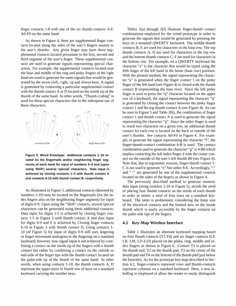
finger contacts 1-8 with one of the six thumb contacts A-F,A0-F0 on the same hand.
As shown in Figure 4, there are supplemental finger con-tacts located along the sides of the user’s fingers nearest tothe user’s thumbs. Any given finger may have three sup-plemental contacts located proximate to the first, second andthird segment of the user’s finger. These supplemental con-tacts are used to generate signals representing special char-acters. For example, the supplemental contacts located nearthe base and middle of the ring and pinky fingers of the righthand are used to generate the same signals that would be gen-erated by the arrow (left, right, up anddown) keys. A signalis generated by contacting a particular supplemental contactwith the thumb contact A or D located on the inside tip of thethumb of the same hand. In other words, “Thumb-coding” isused for these special characters due to the infrequent use ofthese characters.
D0
1 2 3 4 5 6 7 8 9 0 − =
; ’
‘
! @ # $ % ^ & * ( ) _ +
[ ] \{ } |
: "
< > ?
~
u
dl rAlt Ins DelAltCtrl
Shift
CapsLock
Back
Esc
Shift
Enter A S D F G H J K L
Z X C V B N M
Q W E R T Y U I O P
, . /
1 23
4
ABC
B0C0A0
8D E
F
E0F0 56 7
A���� 3F /������ ./�!����� �,# ( ���!055 %� ���� ������� � ������������ �������� ���P����' � ������" �� � �������� ��� ��� ���������� ��������� ��� ���� �� ��������� ������ �3�7�" ��������� ����� �0�2� ��� ��� �� ������� � ������� ��"�5�" �9"95�" �%"%5� �� ���������������� �� �" ���� � ��� ��� �" ������ � ������� �$"$5�" �8"85�" �A"A5� �� ����������� ���� �� �" ���� � ��� ��� �" �������������
(8)
{[
}]
+=
:;
Ctrl
Alt
~‘
Caps Lock
Shift
Space
Shift
Back
Enter
Ins
"’
l
ru
d
Tab
Del
Esc
_−
|\
Left Hand (TOP) Right Hand (TOP)
DA
(B0)
(C0)
(D0)
(E)
(F)
(F0)
(E0)
(A0)
(B)
(C)
(1)
(2)
(4)
(6)(3)
(5) (7)
A���� 1F G����� � �� ������� ������� �3�2�������� ����� �������� ������ � ��� ������ � ���������" �� ��� � ������� ���5� � $�5�� ��� �� P���������' ������� � P�������' ������� ������
10
Left Hand (TOP) Right Hand (TOP)
DA
75
4 6
32
1
89
A���� ;F ��������� ������� 3Y35 ������ � ������������ ���* ��������� ���� ��� ���� ����� ���� � ���������� ����� � �� ��� 5Y6��� ���� ����� P/����'� ������ P�������' ���������$��� ����� �� �������� �� ������ ������� 3Y0 ������� � ������ � ��� ������� 4�35 ���� ��� � ������� 9" ������������
A���� 7F �F =��������� ������ ������� 9��� F �%���!��� �!�������������� �������
Figure 5. Wired Prototype: Additional contacts 1–10 lo-
cated on the fingernails and/or neighboring finger seg-
ments of each hand for input of numbers 0–9 and (upon
using ‘Shift’) several ‘special’ characters. Data input is
achieved by closing contacts 1–5 with thumb contact A
and contacts 6-10 with thumb contact B, respectively.
As illustrated in Figure 5, additional contacts (denoted bynumbers 1-10) may be located on the fingernails (for the in-dex fingers also on the neighboring finger segment) for inputof digits 0-9. Upon using the “Shift” contacts, several specialcharacters can be generated using these additional contacts.Data input for digits 1-5 is achieved by closing finger con-tacts 1-5 in Figure 3 with thumb contact A and data inputfor digits 6-9 and 0 is achieved by Closing finger contacts6-10 in Figure 3 with thumb contact D. Using contacts 1-10 (of Figure 5) for input of digits 0-9 still uses fingeringor finger movement analogous to the fingering on a standardkeyboard; however, now signal input is not achieved by com-bining a contact on the inside tip of the fingers with a thumbcontact but rather by combining a contact on the outside ornail-side of the finger tips with the thumb contact located onthe palm-side tip of the thumb of the same hand. In otherwords, when using contacts 1-10, the thumb contacts A, Drepresent the upper-most or fourth row of keys on a standardkeyboard carrying the number keys.
Tables 2(a) through 2(f) illustrate finger-thumb contactcombinations employed for the wired prototype in order togenerate the signals that would be generated by pressing thekeys on a standard QWERTY keyboard. The middle thumbcontacts B, E are used for characters in the base row. The topthumb contacts A, D are used for characters in the top rowand the bottom thumb contacts C, F are used for characters inthe bottom row. For example, on a QWERTY keyboard thecharacter “a” is the character that would be typed using thefifth finger of the left hand in the home (base row) position.With the present method, the signal representing the charac-ter “a” is generated when the finger contact 1 on the pinkyfinger of the left hand (see Figure 4) is closed with the thumbcontact B (representing the base row). Since the left pinkyfinger is used to press the “q” character located on the upperrow of a keyboard, the signal representing the character “q”is generated by closing the contact between the pinky fingercontact 1 and the top thumb contact A (see Figure 4). As canbe seen in Figure 3 and Table 2(b), the combination of fingercontact 1 and thumb contact A is used to generate the signalrepresenting the character “q”. Since the index finger is usedto reach two characters on a given row, an additional thumbcontact for each row is located on the back or outside of theuser’s thumbs. See contacts A0-F0 in Figure 4. For exam-ple, to generate the signal representing the character “f”, thefinger-thumb-contact combination 4-B is used. The contactcombination used to generate the character “g” is 4-B0 whichimplies contacting the left index finger 4 with the center con-tact on the outside of the user’s left thumb B0 (see Figure 4).Note that, due to ergonomic reasons, finger-thumb contact 1-C is not used to generate “z” but rather 8-E. Accordingly, “;”and “ :” are generated by one of the supplemental contactslocated on the sides of the fingers as shown in Figure 4.
The previously described method to generate numericdata input (using contacts 1-10 in Figure 5), avoids the needof placing four thumb contacts on the inside of each thumbin order to mimic a total of four rows on a standard key-board. The latter is problematic considering the finite sizeof the electrical contacts and the limited area on the insidethumb which is easily accessible by the finger contacts onthe palm-side tips of the fingers.
4.3 Key-Map Wireless Interface
Table 1 illustrates an alternate keyboard mapping basedon four thumb contacts (T1-T4) and six finger contacts (LP,LR, LM, LI1-LI3) placed on the pinky, ring, middle and in-dex fingers as shown in Figure 6. Contact T1 is placed onthe thumb nail, T2 on the thumb pad, T3 on the center of thethumb pad and T4 on the bottom of the thumb pad (just belowthe knuckle). As for the prototype key-map described in Sec-tion 4.2, finger-contacts represent rows and thumb-contactsrepresent columns on a standard keyboard. Here, a new la-belling is employed to allow the reader to easily distinguish
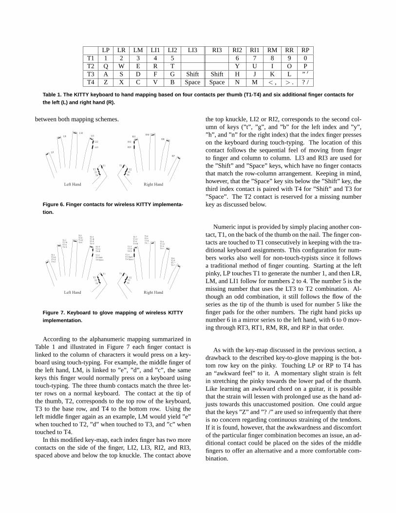
LP LR LM LI1 LI2 LI3 RI3 RI2 RI1 RM RR RPT1 1 2 3 4 5 6 7 8 9 0T2 Q W E R T Y U I O PT3 A S D F G Shift Shift H J K L ” ′
T4 Z X C V B Space Space N M < , > . ? /
Table 1. The KITTY keyboard to hand mapping based on four contacts per thumb (T1-T4) and six additional finger contacts for
the left (L) and right hand (R).
between both mapping schemes.
Left Hand Right Hand
LP
T1T2
T3T4
T1
T2T3
T4
LRLM
LI1
LI2
LI3
RMRI1
RI2
RI3
RR
RP
Figure 6. Finger contacts for wireless KITTY implementa-
tion.
Left Hand Right Hand
TI-1T2-QT3-AT4-Z
T1T2
T3T4
T1
T2T3
T4
TI-2T2-WT3-ST4-X
TI-3T2-ET3-DT4-C
TI-4T2-RT3-FT4-V
T2-TT3-GT4-B
T2-5T3-ShiftT4-Space
TI-7T2-UT3-JT4-M
TI-8T2-IT3-KT4-< , TI-9
T2-OT3-LT4-> .
TI-0T2-PT3-" 'T4-? /
T2-6T3-ShiftT4-Space
T2-YT3-HT4-N
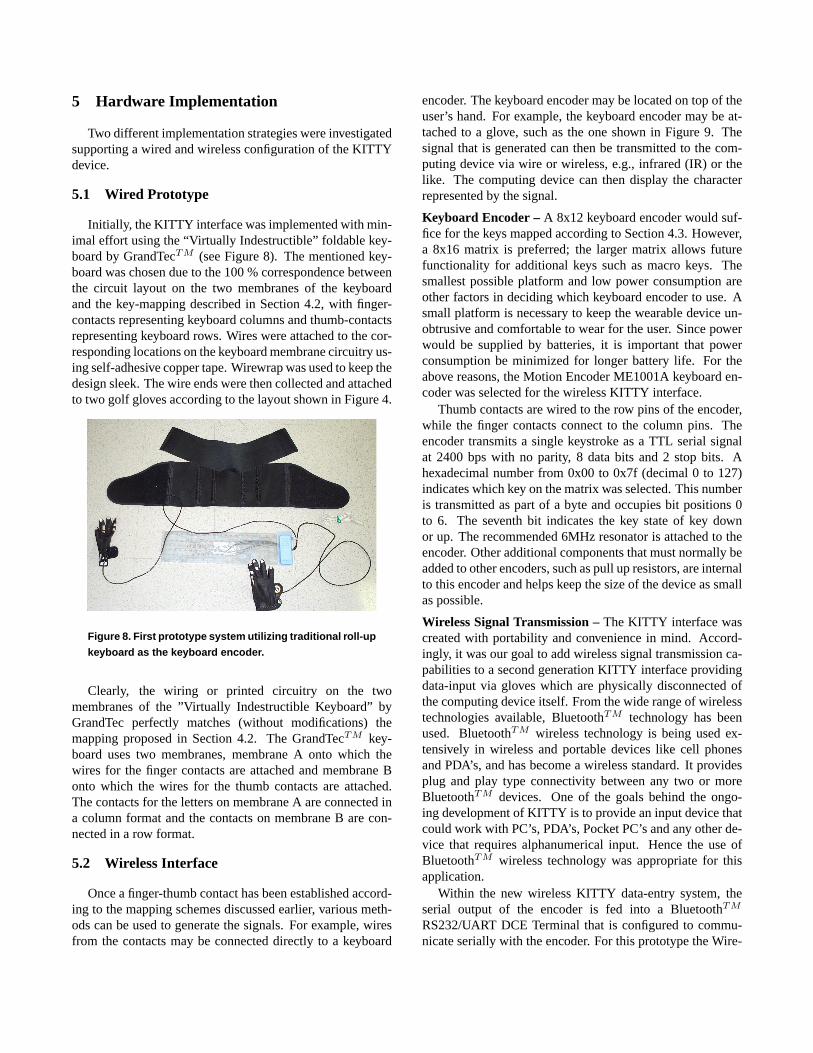
Figure 7. Keyboard to glove mapping of wireless KITTY
implementation.
According to the alphanumeric mapping summarized inTable 1 and illustrated in Figure 7 each finger contact islinked to the column of characters it would press on a key-board using touch-typing. For example, the middle finger ofthe left hand, LM, is linked to ”e”, ”d”, and ”c”, the samekeys this finger would normally press on a keyboard usingtouch-typing. The three thumb contacts match the three let-ter rows on a normal keyboard. The contact at the tip ofthe thumb, T2, corresponds to the top row of the keyboard,T3 to the base row, and T4 to the bottom row. Using theleft middle finger again as an example, LM would yield ”e”when touched to T2, ”d” when touched to T3, and ”c” whentouched to T4.
In this modified key-map, each index finger has two morecontacts on the side of the finger, LI2, LI3, RI2, and RI3,spaced above and below the top knuckle. The contact above
the top knuckle, LI2 or RI2, corresponds to the second col-umn of keys (”t”, ”g”, and ”b” for the left index and ”y”,”h”, and ”n” for the right index) that the index finger presseson the keyboard during touch-typing. The location of thiscontact follows the sequential feel of moving from fingerto finger and column to column. LI3 and RI3 are used forthe ”Shift” and ”Space” keys, which have no finger contactsthat match the row-column arrangement. Keeping in mind,however, that the ”Space” key sits below the ”Shift” key, thethird index contact is paired with T4 for ”Shift” and T3 for”Space”. The T2 contact is reserved for a missing numberkey as discussed below.
Numeric input is provided by simply placing another con-tact, T1, on the back of the thumb on the nail. The finger con-tacts are touched to T1 consecutively in keeping with the tra-ditional keyboard assignments. This configuration for num-bers works also well for non-touch-typists since it followsa traditional method of finger counting. Starting at the leftpinky, LP touches T1 to generate the number 1, and then LR,LM, and LI1 follow for numbers 2 to 4. The number 5 is themissing number that uses the LT3 to T2 combination. Al-though an odd combination, it still follows the flow of theseries as the tip of the thumb is used for number 5 like thefinger pads for the other numbers. The right hand picks upnumber 6 in a mirror series to the left hand, with 6 to 0 mov-ing through RT3, RT1, RM, RR, and RP in that order.
As with the key-map discussed in the previous section, adrawback to the described key-to-glove mapping is the bot-tom row key on the pinky. Touching LP or RP to T4 hasan “awkward feel” to it. A momentary slight strain is feltin stretching the pinky towards the lower pad of the thumb.Like learning an awkward chord on a guitar, it is possiblethat the strain will lessen with prolonged use as the hand ad-justs towards this unaccustomed position. One could arguethat the keys ”Z” and ”? /” are used so infrequently that thereis no concern regarding continuous straining of the tendons.If it is found, however, that the awkwardness and discomfortof the particular finger combination becomes an issue, an ad-ditional contact could be placed on the sides of the middlefingers to offer an alternative and a more comfortable com-bination.
5 Hardware Implementation
Two different implementation strategies were investigatedsupporting a wired and wireless configuration of the KITTYdevice.
5.1 Wired Prototype
Initially, the KITTY interface was implemented with min-imal effort using the “Virtually Indestructible” foldable key-board by GrandTecTM (see Figure 8). The mentioned key-board was chosen due to the 100 % correspondence betweenthe circuit layout on the two membranes of the keyboardand the key-mapping described in Section 4.2, with finger-contacts representing keyboard columns and thumb-contactsrepresenting keyboard rows. Wires were attached to the cor-responding locations on the keyboard membrane circuitry us-ing self-adhesive copper tape. Wirewrap was used to keep thedesign sleek. The wire ends were then collected and attachedto two golf gloves according to the layout shown in Figure 4.
Figure 8. First prototype system utilizing traditional roll-up
keyboard as the keyboard encoder.
Clearly, the wiring or printed circuitry on the twomembranes of the ”Virtually Indestructible Keyboard” byGrandTec perfectly matches (without modifications) themapping proposed in Section 4.2. The GrandTecTM key-board uses two membranes, membrane A onto which thewires for the finger contacts are attached and membrane Bonto which the wires for the thumb contacts are attached.The contacts for the letters on membrane A are connected ina column format and the contacts on membrane B are con-nected in a row format.
5.2 Wireless Interface
Once a finger-thumb contact has been established accord-ing to the mapping schemes discussed earlier, various meth-ods can be used to generate the signals. For example, wiresfrom the contacts may be connected directly to a keyboard
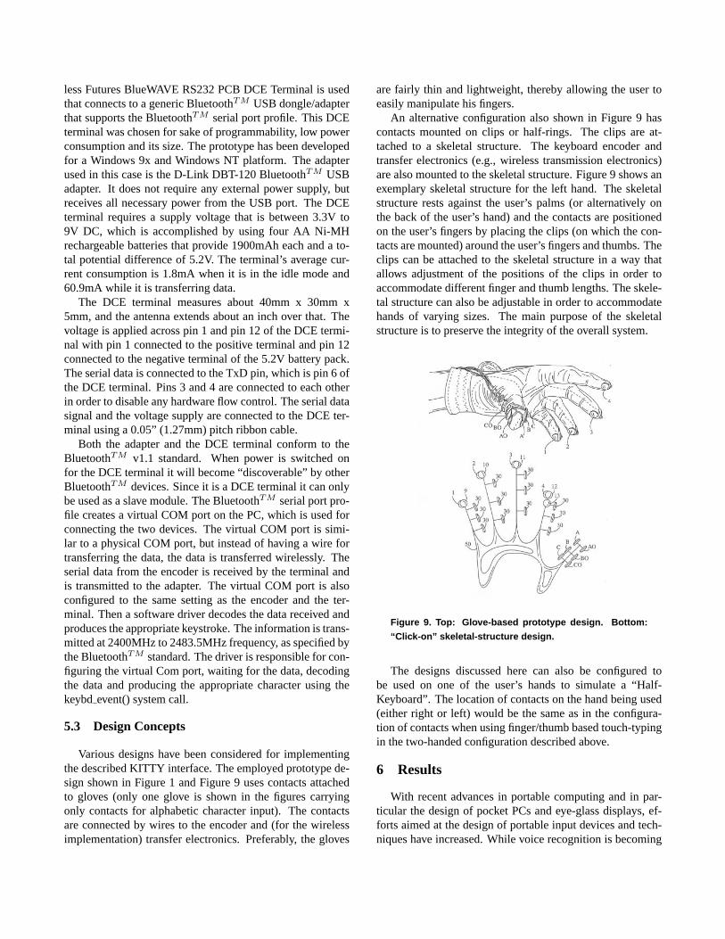
encoder. The keyboard encoder may be located on top of theuser’s hand. For example, the keyboard encoder may be at-tached to a glove, such as the one shown in Figure 9. Thesignal that is generated can then be transmitted to the com-puting device via wire or wireless, e.g., infrared (IR) or thelike. The computing device can then display the characterrepresented by the signal.
Keyboard Encoder –A 8x12 keyboard encoder would suf-fice for the keys mapped according to Section 4.3. However,a 8x16 matrix is preferred; the larger matrix allows futurefunctionality for additional keys such as macro keys. Thesmallest possible platform and low power consumption areother factors in deciding which keyboard encoder to use. Asmall platform is necessary to keep the wearable device un-obtrusive and comfortable to wear for the user. Since powerwould be supplied by batteries, it is important that powerconsumption be minimized for longer battery life. For theabove reasons, the Motion Encoder ME1001A keyboard en-coder was selected for the wireless KITTY interface.
Thumb contacts are wired to the row pins of the encoder,while the finger contacts connect to the column pins. Theencoder transmits a single keystroke as a TTL serial signalat 2400 bps with no parity, 8 data bits and 2 stop bits. Ahexadecimal number from 0x00 to 0x7f (decimal 0 to 127)indicates which key on the matrix was selected. This numberis transmitted as part of a byte and occupies bit positions 0to 6. The seventh bit indicates the key state of key downor up. The recommended 6MHz resonator is attached to theencoder. Other additional components that must normally beadded to other encoders, such as pull up resistors, are internalto this encoder and helps keep the size of the device as smallas possible.
Wireless Signal Transmission –The KITTY interface wascreated with portability and convenience in mind. Accord-ingly, it was our goal to add wireless signal transmission ca-pabilities to a second generation KITTY interface providingdata-input via gloves which are physically disconnected ofthe computing device itself. From the wide range of wirelesstechnologies available, BluetoothTM technology has beenused. BluetoothTM wireless technology is being used ex-tensively in wireless and portable devices like cell phonesand PDA’s, and has become a wireless standard. It providesplug and play type connectivity between any two or moreBluetoothTM devices. One of the goals behind the ongo-ing development of KITTY is to provide an input device thatcould work with PC’s, PDA’s, Pocket PC’s and any other de-vice that requires alphanumerical input. Hence the use ofBluetoothTM wireless technology was appropriate for thisapplication.
Within the new wireless KITTY data-entry system, theserial output of the encoder is fed into a BluetoothTM
RS232/UART DCE Terminal that is configured to commu-nicate serially with the encoder. For this prototype the Wire-
less Futures BlueWAVE RS232 PCB DCE Terminal is usedthat connects to a generic BluetoothTM USB dongle/adapterthat supports the BluetoothTM serial port profile. This DCEterminal was chosen for sake of programmability, low powerconsumption and its size. The prototype has been developedfor a Windows 9x and Windows NT platform. The adapterused in this case is the D-Link DBT-120 BluetoothTM USBadapter. It does not require any external power supply, butreceives all necessary power from the USB port. The DCEterminal requires a supply voltage that is between 3.3V to9V DC, which is accomplished by using four AA Ni-MHrechargeable batteries that provide 1900mAh each and a to-tal potential difference of 5.2V. The terminal’s average cur-rent consumption is 1.8mA when it is in the idle mode and60.9mA while it is transferring data.
The DCE terminal measures about 40mm x 30mm x5mm, and the antenna extends about an inch over that. Thevoltage is applied across pin 1 and pin 12 of the DCE termi-nal with pin 1 connected to the positive terminal and pin 12connected to the negative terminal of the 5.2V battery pack.The serial data is connected to the TxD pin, which is pin 6 ofthe DCE terminal. Pins 3 and 4 are connected to each otherin order to disable any hardware flow control. The serial datasignal and the voltage supply are connected to the DCE ter-minal using a 0.05” (1.27mm) pitch ribbon cable.
Both the adapter and the DCE terminal conform to theBluetoothTM v1.1 standard. When power is switched onfor the DCE terminal it will become “discoverable” by otherBluetoothTM devices. Since it is a DCE terminal it can onlybe used as a slave module. The BluetoothTM serial port pro-file creates a virtual COM port on the PC, which is used forconnecting the two devices. The virtual COM port is simi-lar to a physical COM port, but instead of having a wire fortransferring the data, the data is transferred wirelessly. Theserial data from the encoder is received by the terminal andis transmitted to the adapter. The virtual COM port is alsoconfigured to the same setting as the encoder and the ter-minal. Then a software driver decodes the data received andproduces the appropriate keystroke. The information is trans-mitted at 2400MHz to 2483.5MHz frequency, as specified bythe BluetoothTM standard. The driver is responsible for con-figuring the virtual Com port, waiting for the data, decodingthe data and producing the appropriate character using thekeybdevent() system call.
5.3 Design Concepts
Various designs have been considered for implementingthe described KITTY interface. The employed prototype de-sign shown in Figure 1 and Figure 9 uses contacts attachedto gloves (only one glove is shown in the figures carryingonly contacts for alphabetic character input). The contactsare connected by wires to the encoder and (for the wirelessimplementation) transfer electronics. Preferably, the gloves
are fairly thin and lightweight, thereby allowing the user toeasily manipulate his fingers.
An alternative configuration also shown in Figure 9 hascontacts mounted on clips or half-rings. The clips are at-tached to a skeletal structure. The keyboard encoder andtransfer electronics (e.g., wireless transmission electronics)are also mounted to the skeletal structure. Figure 9 shows anexemplary skeletal structure for the left hand. The skeletalstructure rests against the user’s palms (or alternatively onthe back of the user’s hand) and the contacts are positionedon the user’s fingers by placing the clips (on which the con-tacts are mounted) around the user’s fingers and thumbs. Theclips can be attached to the skeletal structure in a way thatallows adjustment of the positions of the clips in order toaccommodate different finger and thumb lengths. The skele-tal structure can also be adjustable in order to accommodatehands of varying sizes. The main purpose of the skeletalstructure is to preserve the integrity of the overall system.
Figure 9. Top: Glove-based prototype design. Bottom:
“Click-on” skeletal-structure design.
The designs discussed here can also be configured tobe used on one of the user’s hands to simulate a “Half-Keyboard”. The location of contacts on the hand being used(either right or left) would be the same as in the configura-tion of contacts when using finger/thumb based touch-typingin the two-handed configuration described above.
6 Results
With recent advances in portable computing and in par-ticular the design of pocket PCs and eye-glass displays, ef-forts aimed at the design of portable input devices and tech-niques have increased. While voice recognition is becoming

a strong contender for next generation input technology, pri-vacy concerns and ambient noise problems are still a chal-lenge and alternative approaches are required. The presentedKITTY interface consists of a finger-mounted device mim-icking finger movements similar to traditional touch-typingin order to provide alphanumerical data input. This low costdevice guarantees a rapid learning curve for everyone expe-rienced in touch-typing while offering significant flexibility.Two prototypes were build one using a PSII and one using aUSB version of the GranTec keyboard. Priced at around $50US for parts the KITTY device proved to be a very cost ef-fective solution. The proof-of-concept implementation of theKITTY device was tested with wearable devices and desktopsystems and demonstrated its effectiveness.
References
[1] Handykey Corporation. www.handykey.com, 2003.[2] M. E. Horn. Single-hand mounted and operated keyboard.
U.S. Patent 5,552,782, September 1996.[3] R. B. Howard. Wrist-pendent wireless optical keybaord. U.S.
Patent 6,097,374, August 2000.[4] Lightglove. www.lightglove.com, 2003.[5] MachineBrain.com. www.machinebrain.com, 2003.[6] E. Matias, I. S. MacKenzie, and W. Buxton. Half-QWERTY:
Typing with one hand using your two-handed skills. InPro-ceedings of ACM CHI’94 Conference on Human Factors inComputing Systems, volume 2 of INTERACTIVE EXPERI-ENCE, pages 51–52, 1994.
[7] E. Matias, I. S. MacKenzie, and W. Buxton. A wearable com-puter for use in microgravity space and other non-desktop en-vironments. InProceedings of ACM CHI 96 Conference onHuman Factors in Computing Systems, volume 2 ofINTER-ACTIVE POSTERS: CHI in Space, pages 69–70, 1996.
[8] Matias Corporation. www.halfkeyboard.com, 2003.[9] R. P. McCarty. Wearables central: Softwear. wear-
ables.blu.org, 2003.[10] V. R. Pratt. Thumb-code: A device-independent digital sign
language, July 1998.[11] K. R. Prince. Finger-mounted computer input device. U.S.
Patent 5,581,484, December 1996.[12] Senseboard Technologies. www.senseboard.com, 2003.[13] Stanford Wearables. wearables.stanford.edu, 2001.[14] The MicroOptical Corporation. www.microopticalcorp.com,
2003.[15] S. Vance, L. Migachyov, W. Fu, and I. Hajjar. Fingerless
glove for interacting with a data processing system. U.S.Patent 6,304,840, October 2001.
[16] A. Wozniak. Pic-key chorded keyboard.http://mudlist.eorbit.net/ adam/pickey/, 1999.
Finger-Thumb Contact Character1-B A2-B S3-B D4-B F4-B0 G
(a) Left-hand base-line characters.
Finger-Thumb Contact Character1-A Q2-A W3-A E4-A R4-A0 T
(b) Left-hand top-line characters.
Finger-Thumb Contact Character1-C Z2-C X3-C C4-C V4-C0 B
(c) Left-hand bottom-line characters.
Finger-Thumb Contact Character5-E0 H5-E J6-E K7-E L8-E Z
(d) Right-hand base-line characters.
Finger-Thumb Contact Character5-D0 Y5-D U6-D I7-D O8-D P
(e) Right-hand top-line characters.
Finger-Thumb Contact Character5-F0 N5-F M6-F <,7-F > .8-F ? /
(f) right-hand bottom-line characters.
Table 2. Prototype Key-Map for KITTY device.