kintore primary school - aberdeenshire
TRANSCRIPT
Kintore Primary School
Cavity Wall Tie Inspection
October 2016
CONTROL SHEET CLIENT: Aberdeenshire Council PROJECT TITLE: Cavity Wall tie inspection at Kintore Primary School REPORT TITLE: Cavity Wall tie inspection at Kintore Primary School PROJECT REFERENCE: 114941 Issue and Approval Schedule:
ISSUE 1 Name Signature Date
Prepared by Oct 16
Reviewed by
Oct 16
Approved by Nov 16
Revision Record:
Issue Date Status Description By Chk App
2
3
4
5
6
7
8
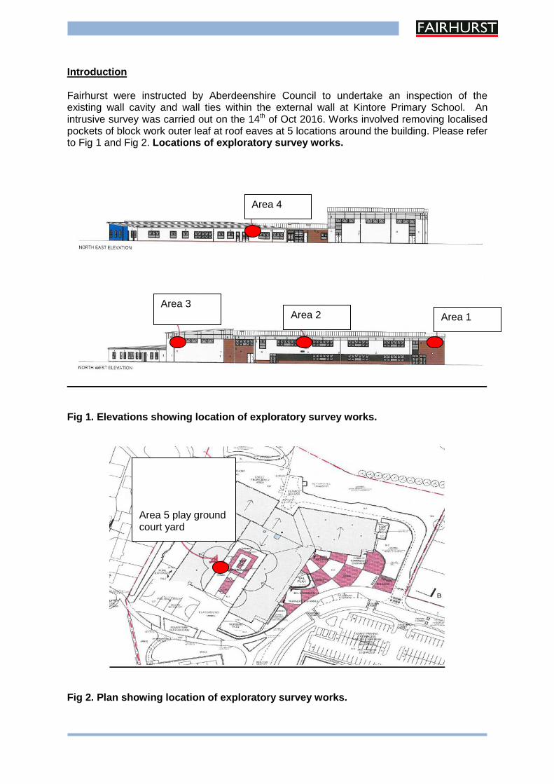
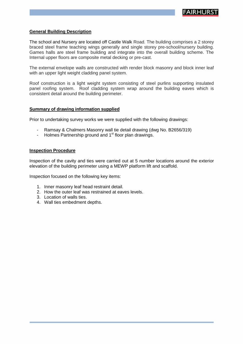
Introduction Fairhurst were instructed by Aberdeenshire Council to undertake an inspection of the existing wall cavity and wall ties within the external wall at Kintore Primary School. An intrusive survey was carried out on the 14th of Oct 2016. Works involved removing localised pockets of block work outer leaf at roof eaves at 5 locations around the building. Please refer to Fig 1 and Fig 2. Locations of exploratory survey works.
Fig 1. Elevations showing location of exploratory survey works.
Fig 2. Plan showing location of exploratory survey works.
Area 1
Area 4
Area 3 Area 2
Area 5 play ground court yard
General Building Description The school and Nursery are located off Castle Walk Road. The building comprises a 2 storey braced steel frame teaching wings generally and single storey pre-school/nursery building. Games halls are steel frame building and integrate into the overall building scheme. The Internal upper floors are composite metal decking or pre-cast. The external envelope walls are constructed with render block masonry and block inner leaf with an upper light weight cladding panel system. Roof construction is a light weight system consisting of steel purlins supporting insulated panel roofing system. Roof cladding system wrap around the building eaves which is consistent detail around the building perimeter. Summary of drawing information supplied Prior to undertaking survey works we were supplied with the following drawings:
- Ramsay & Chalmers Masonry wall tie detail drawing (dwg No. B2656/319) - Holmes Partnership ground and 1st floor plan drawings.
Inspection Procedure Inspection of the cavity and ties were carried out at 5 number locations around the exterior elevation of the building perimeter using a MEWP platform lift and scaffold. Inspection focused on the following key items:
1. Inner masonry leaf head restraint detail. 2. How the outer leaf was restrained at eaves levels. 3. Location of walls ties. 4. Wall ties embedment depths.
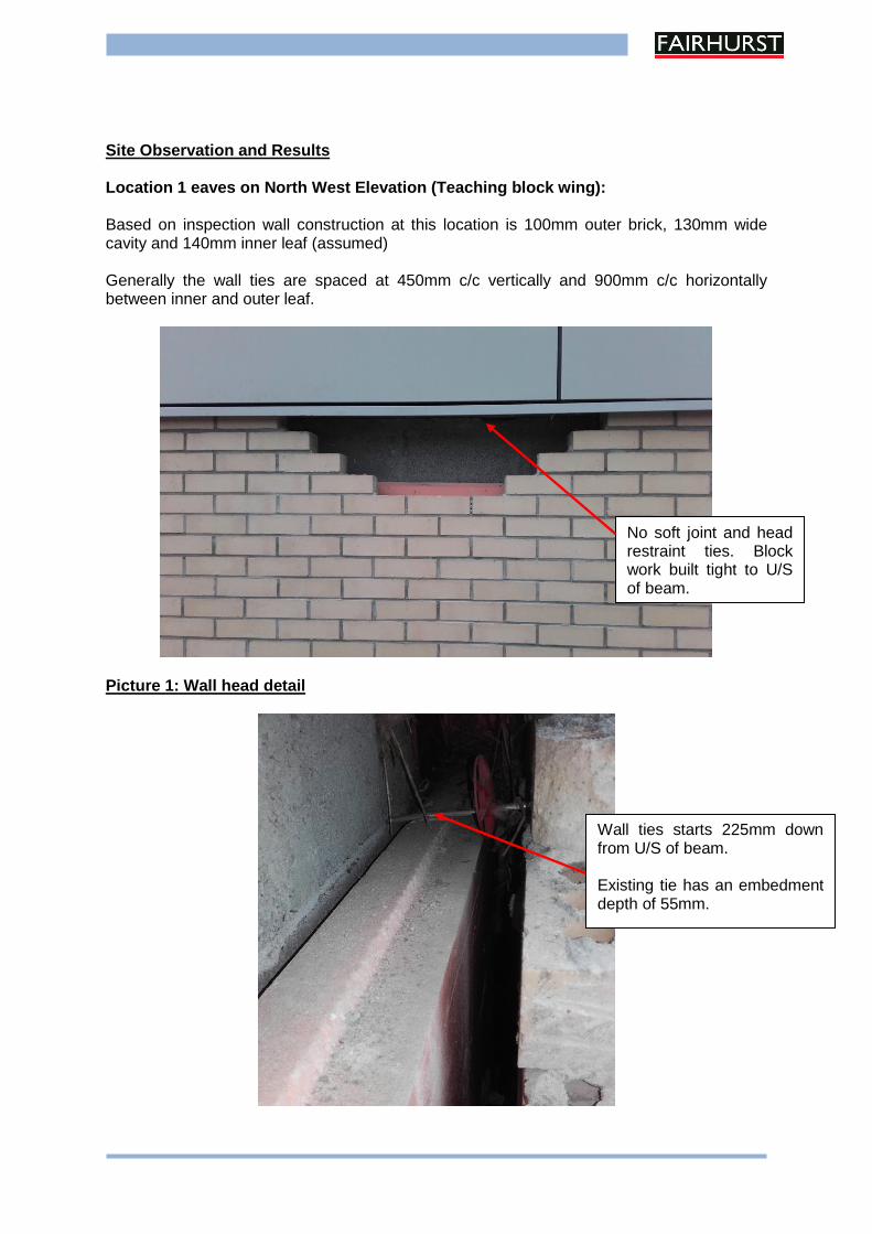
Site Observation and Results Location 1 eaves on North West Elevation (Teaching block wing): Based on inspection wall construction at this location is 100mm outer brick, 130mm wide cavity and 140mm inner leaf (assumed) Generally the wall ties are spaced at 450mm c/c vertically and 900mm c/c horizontally between inner and outer leaf.
Picture 1: Wall head detail
No soft joint and head restraint ties. Block work built tight to U/S of beam.
Wall ties starts 225mm down from U/S of beam. Existing tie has an embedment depth of 55mm.
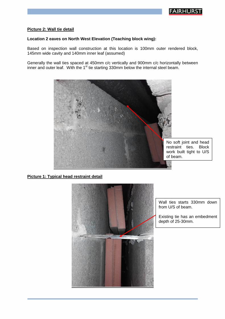
Picture 2: Wall tie detail
Location 2 eaves on North West Elevation (Teaching block wing): Based on inspection wall construction at this location is 100mm outer rendered block, 145mm wide cavity and 140mm inner leaf (assumed) Generally the wall ties spaced at 450mm c/c vertically and 900mm c/c horizontally between inner and outer leaf. With the 1st tie starting 330mm below the internal steel beam.
Picture 1: Typical head restraint detail
No soft joint and head restraint ties. Block work built tight to U/S of beam.
Wall ties starts 330mm down from U/S of beam. Existing tie has an embedment depth of 25-30mm.
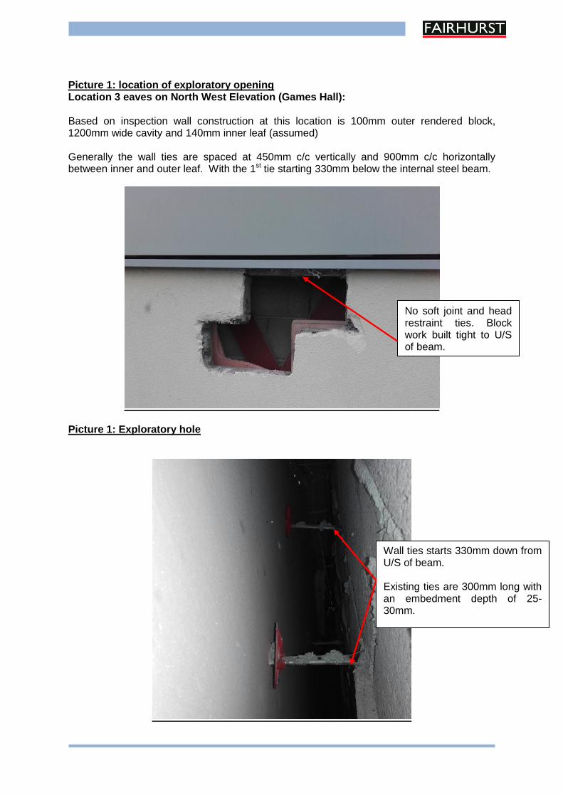
Picture 1: location of exploratory opening Location 3 eaves on North West Elevation (Games Hall): Based on inspection wall construction at this location is 100mm outer rendered block, 1200mm wide cavity and 140mm inner leaf (assumed) Generally the wall ties are spaced at 450mm c/c vertically and 900mm c/c horizontally between inner and outer leaf. With the 1st tie starting 330mm below the internal steel beam.
Picture 1: Exploratory hole
No soft joint and head restraint ties. Block work built tight to U/S of beam.
Wall ties starts 330mm down from U/S of beam. Existing ties are 300mm long with an embedment depth of 25-30mm.
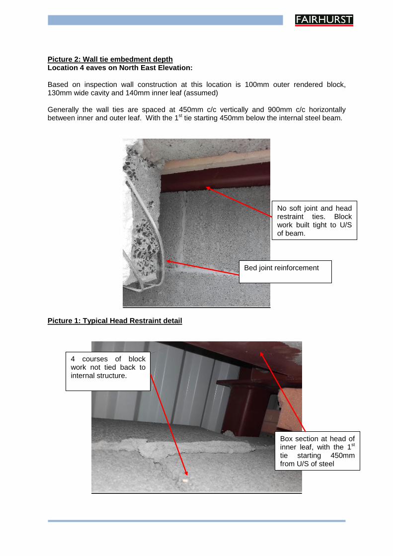
Picture 2: Wall tie embedment depth Location 4 eaves on North East Elevation:
Based on inspection wall construction at this location is 100mm outer rendered block, 130mm wide cavity and 140mm inner leaf (assumed) Generally the wall ties are spaced at 450mm c/c vertically and 900mm c/c horizontally between inner and outer leaf. With the 1st tie starting 450mm below the internal steel beam.
Picture 1: Typical Head Restraint detail
No soft joint and head restraint ties. Block work built tight to U/S of beam.
Bed joint reinforcement
Box section at head of inner leaf, with the 1st tie starting 450mm from U/S of steel
4 courses of block work not tied back to internal structure.
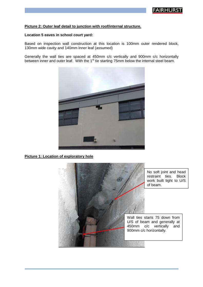
Picture 2: Outer leaf detail to junction with roof/internal structure. Location 5 eaves in school court yard:
Based on inspection wall construction at this location is 100mm outer rendered block, 130mm wide cavity and 140mm inner leaf (assumed) Generally the wall ties are spaced at 450mm c/c vertically and 900mm c/c horizontally between inner and outer leaf. With the 1st tie starting 75mm below the internal steel beam.
Picture 1: Location of exploratory hole
No soft joint and head restraint ties. Block work built tight to U/S of beam.
Wall ties starts 75 down from U/S of beam and generally at 450mm c/c vertically and 900mm c/c horizontally.
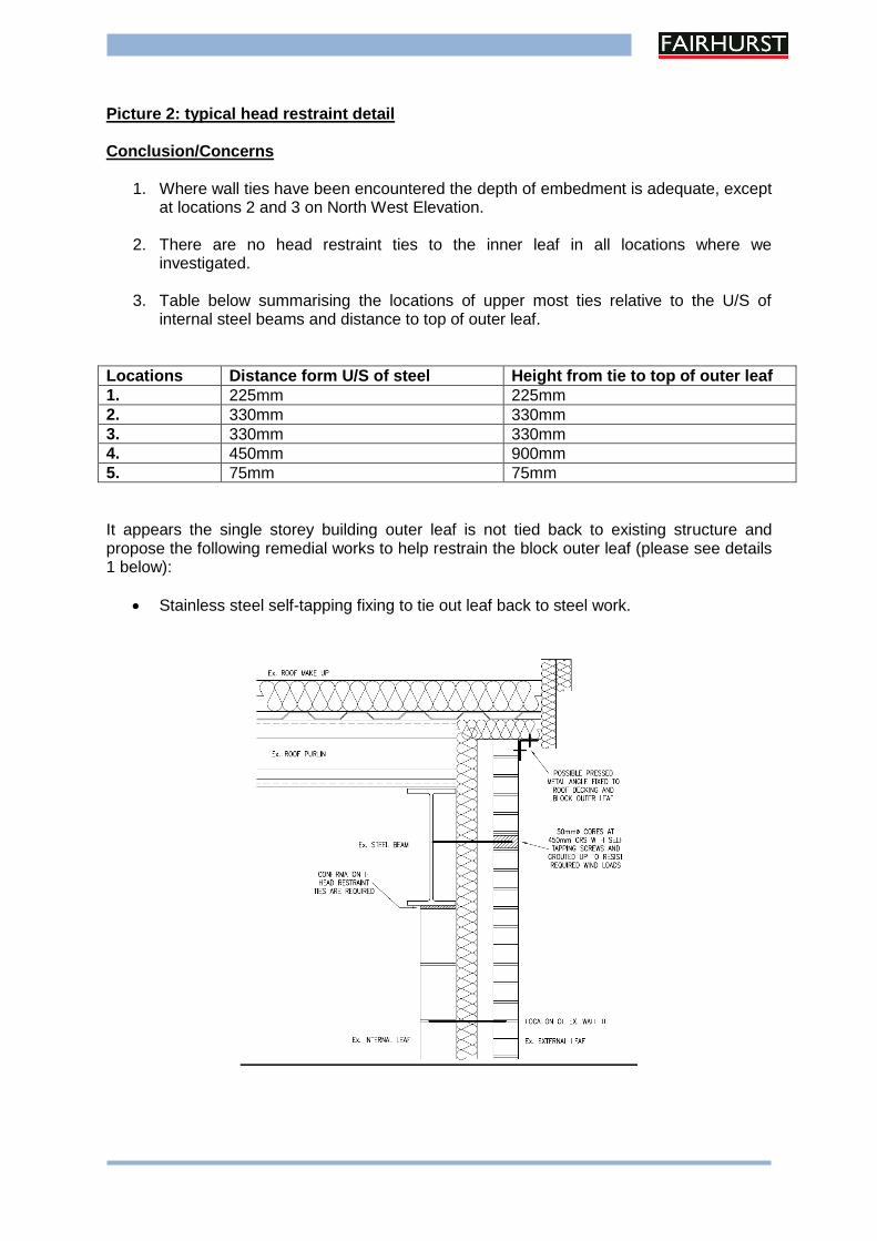
Picture 2: typical head restraint detail Conclusion/Concerns
1. Where wall ties have been encountered the depth of embedment is adequate, except at locations 2 and 3 on North West Elevation.
2. There are no head restraint ties to the inner leaf in all locations where we
investigated.
3. Table below summarising the locations of upper most ties relative to the U/S of internal steel beams and distance to top of outer leaf.
Locations Distance form U/S of steel Height from tie to top of outer leaf
1. 225mm 225mm
2. 330mm 330mm
3. 330mm 330mm
4. 450mm 900mm
5. 75mm 75mm
It appears the single storey building outer leaf is not tied back to existing structure and propose the following remedial works to help restrain the block outer leaf (please see details 1 below):
Stainless steel self-tapping fixing to tie out leaf back to steel work.
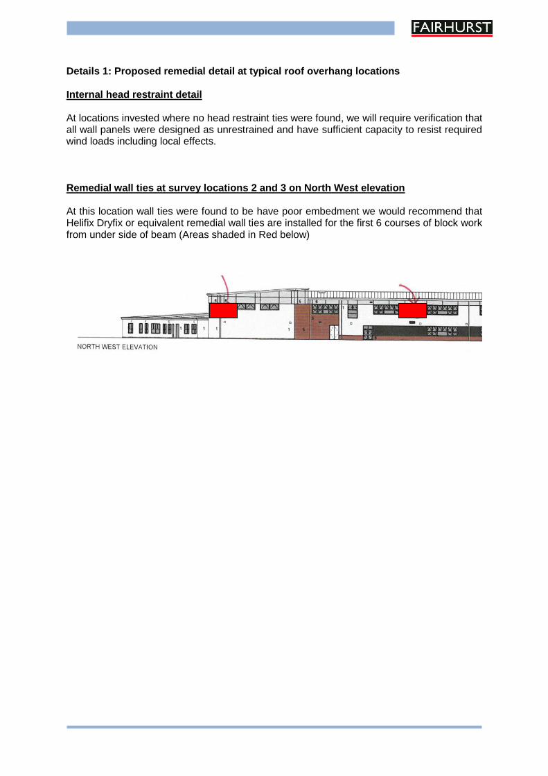
Details 1: Proposed remedial detail at typical roof overhang locations Internal head restraint detail At locations invested where no head restraint ties were found, we will require verification that all wall panels were designed as unrestrained and have sufficient capacity to resist required wind loads including local effects. Remedial wall ties at survey locations 2 and 3 on North West elevation At this location wall ties were found to be have poor embedment we would recommend that Helifix Dryfix or equivalent remedial wall ties are installed for the first 6 courses of block work from under side of beam (Areas shaded in Red below)
www.fairhurst.co.uk
Aberdeen Birmingham
Bristol Dundee
Edinburgh Elgin
Glasgow
Inverness Leeds
London Manchester
Newcastle upon Tyne Sheffield Watford
Wellesbourne
CIVIL ENGINEERING • STRUCTURAL ENGINEERING • TRANSPORTATION • ROADS & BRIDGES PORTS & HARBOURS • GEOTECHNICAL & ENVIRONMENTAL ENGINEERING • PLANNING & DEVELOPMENT • WATER SERVICES • CDM COORDINATOR SERVICES