kinematic model of 3d tactile sensing on robotic surfaces
TRANSCRIPT
Kinematic Model of 3D Tactile Sensing on Robotic Surfaces
BHARGAV GAJJAR Space Robotics Corporation 10860 East Oakwood Drive
Tucson, AZ 85749, USA http://www.space-robotics.com
JANUSZ ZALEWSKI Dept. of Computer Science
Florida Gulf Coast University Fort Myers, FL 33965, USA
http://www.fgcu.edu/zalewski/
Abstract: - This paper discusses a matrix based algorithm to sense unknown forces acting on a 3D tactile skin consisting of thin film force sensors. The skin can be mounted on any robotic system to measure forces acting on the robot’s surface upon contact. The paper describes a kinematic model of the forces acting on the skin, stiffness of the skin and an analytical method to extract the value of unknown forces acting in between the discrete sensor array. Key-Words: - Robot kinematics, robotic surfaces, tactile sensing. 1 Introduction Recently the interest in large area flexible force sensing on robot surfaces has increased due to availability of cost effective thin film pressure and force transducers [1]. Several researchers have developed different tactile skins for robotic applications [2-6], however, two major types of force sensing smart skin technologies are predominant on the market: a) force sensing resistor film, and b) force sensing capacitor technologies. While many types of smart skins are being developed, a general mechanism for analyzing the data from these arrays of large number of sensors is not readily available. In this paper, we describe the kinematic model of a force sensing resistive film and a general algorithm for force sensing.
A force sensing resistor is a special piezoresistive conductive polymer, which shows a resistance in a predictable manner after impingement of the force. This type of sensor is manufactured by screen printing and is supplied as a thin sheet. The sensing element in the film consists of both electrically conducting and non-conducting particles suspended in a matrix. Both the electrically conducting and the non conducting particle sizes are of the order of a fraction of microns. Applying a force to the surface of the sensing film causes particles to touch the conducting electrodes, changing the resistance of the film. As with all resistive based sensors, the force
sensitive resistor requires a relatively simple interface and can operate satisfactorily in moderately hostile environments. The force sensitivity of these sensors is given by the formula:
1cGF
Kαρ
(1)
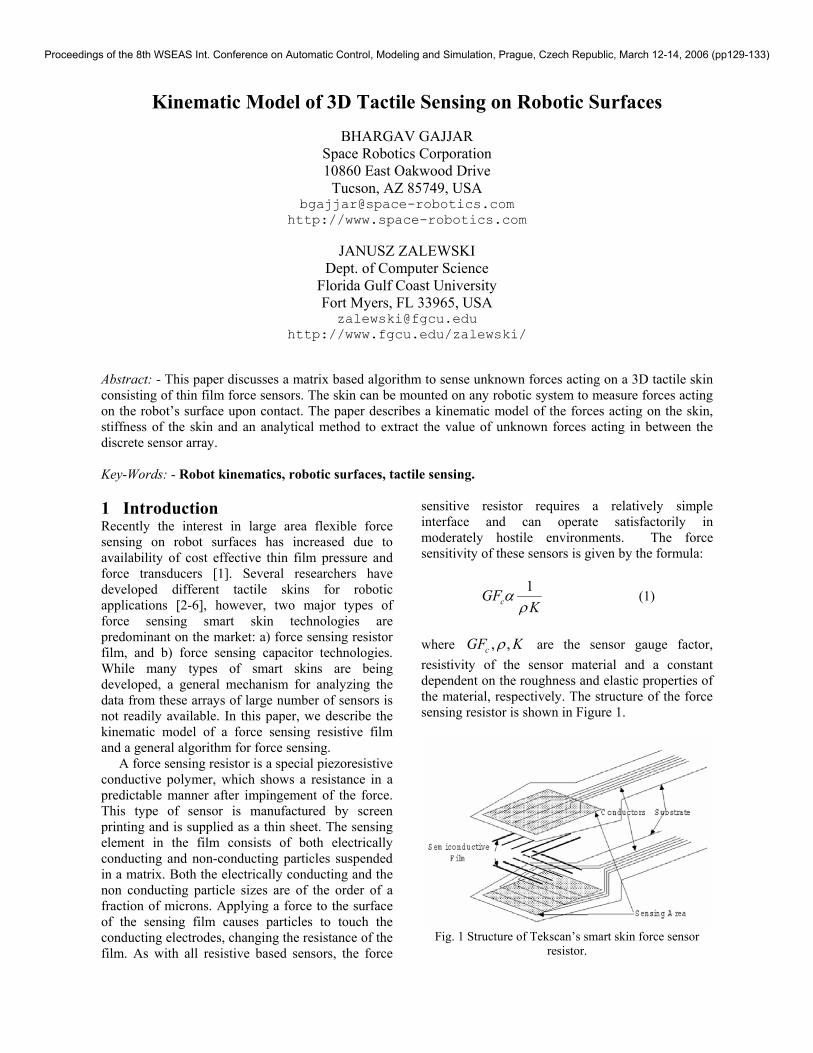
where , ,cGF Kρ are the sensor gauge factor, resistivity of the sensor material and a constant dependent on the roughness and elastic properties of the material, respectively. The structure of the force sensing resistor is shown in Figure 1.
Fig. 1 Structure of Tekscan’s smart skin force sensor resistor.
Proceedings of the 8th WSEAS Int. Conference on Automatic Control, Modeling and Simulation, Prague, Czech Republic, March 12-14, 2006 (pp129-133)
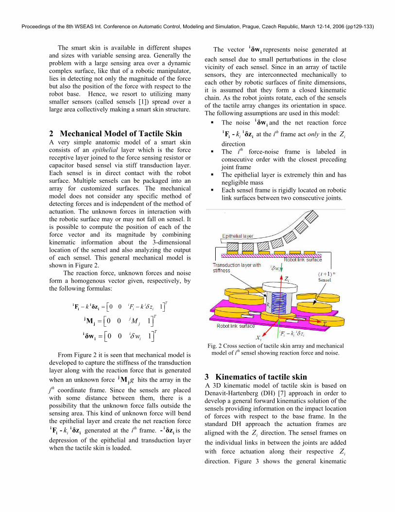
The smart skin is available in different shapes and sizes with variable sensing area. Generally the problem with a large sensing area over a dynamic complex surface, like that of a robotic manipulator, lies in detecting not only the magnitude of the force but also the position of the force with respect to the robot base. Hence, we resort to utilizing many smaller sensors (called sensels [1]) spread over a large area collectively making a smart skin structure. 2 Mechanical Model of Tactile Skin A very simple anatomic model of a smart skin consists of an epithelial layer which is the force receptive layer joined to the force sensing resistor or capacitor based sensel via stiff transduction layer. Each sensel is in direct contact with the robot surface. Multiple sensels can be packaged into an array for customized surfaces. The mechanical model does not consider any specific method of detecting forces and is independent of the method of actuation. The unknown forces in interaction with the robotic surface may or may not fall on sensel. It is possible to compute the position of each of the force vector and its magnitude by combining kinematic information about the 3-dimensional location of the sensel and also analyzing the output of each sensel. This general mechanical model is shown in Figure 2.
The reaction force, unknown forces and noise form a homogenous vector given, respectively, by the following formulas:
0 0 1Ti i
i ik F k zδ − = − i i
i iF δz
0 0 1Tj
jM = j
jM
0 0 1Ti
iwδ = i
iδw
From Figure 2 it is seen that mechanical model is
developed to capture the stiffness of the transduction layer along with the reaction force that is generated when an unknown force gj
jM hits the array in the jth coordinate frame. Since the sensels are placed with some distance between them, there is a possibility that the unknown force falls outside the sensing area. This kind of unknown force will bend the epithelial layer and create the net reaction force
iki ii iF - δz generated at the ith frame. i
i- δz is the depression of the epithelial and transduction layer when the tactile skin is loaded.
The vector iiδw represents noise generated at
each sensel due to small perturbations in the close vicinity of each sensel. Since in an array of tactile sensors, they are interconnected mechanically to each other by robotic surfaces of finite dimensions, it is assumed that they form a closed kinematic chain. As the robot joints rotate, each of the sensels of the tactile array changes its orientation in space. The following assumptions are used in this model:
The noise iiδw and the net reaction force
iki ii iF - δz at the ith frame act only in the iZ
direction The ith force-noise frame is labeled in
consecutive order with the closest preceding joint frame
The epithelial layer is extremely thin and has negligible mass
Each sensel frame is rigidly located on robotic link surfaces between two consecutive joints.
Fig. 2 Cross section of tactile skin array and mechanical
model of ith sensel showing reaction force and noise. 3 Kinematics of tactile skin A 3D kinematic model of tactile skin is based on Denavit-Hartenberg (DH) [7] approach in order to develop a general forward kinematics solution of the sensels providing information on the impact location of forces with respect to the base frame. In the standard DH approach the actuation frames are aligned with the iZ direction. The sensel frames on the individual links in between the joints are added with force actuation along their respective iZ direction. Figure 3 shows the general kinematic
Proceedings of the 8th WSEAS Int. Conference on Automatic Control, Modeling and Simulation, Prague, Czech Republic, March 12-14, 2006 (pp129-133)
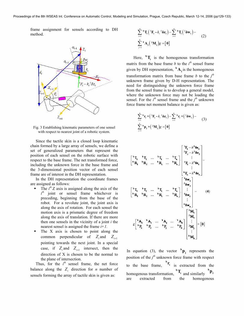
frame assignment for sensels according to DH method.
Fig. 3 Establishing kinematic parameters of one sensel
with respect to nearest joint of a robotic system.
Since the tactile skin is a closed loop kinematic chain formed by a large array of sensels, we define a set of generalized parameters that represent the position of each sensel on the robotic surface with respect to the base frame. The net transformed force, including the unknown force in the base frame and the 3-dimensional position vector of each sensel frame are of interest in the DH representation.
In the DH representation the coordinate frames are assigned as follows:
The ith Z axis is assigned along the axis of the ith joint or sensel frame whichever is preceding, beginning from the base of the robot. For a revolute joint, the joint axis is along the axis of rotation. For each sensel the motion axis is a prismatic degree of freedom along the axis of translation. If there are more then one sensels in the vicinity of a joint i the nearest sensel is assigned the frame i+1.
The X axis is chosen to point along the common perpendicular of iZ and 1iZ + pointing towards the next joint. In a special case, if iZ and 1iZ + intersect, then the direction of X is chosen to be the normal to the plane of intersection.
Thus, for the ith sensel frame, the net force balance along the iZ direction for n number of sensels forming the array of tactile skin is given as:
( ) ( )
( ) [ ]1 1
1
n n
ii ik
j
k
g
= =
=
− −
=
∑ ∑
∑
b i i b ii i i i i
b jj j
T F - δz T δw
A M 0
(2)
Here, b
iT is the homogenous transformation matrix from the base frame b to the ith sensel frame given by DH representation, b
jA is the homogenous transformation matrix from base frame b to the jth unknown frame given by D-H representation. The need for distinguishing the unknown force frame from the sensel frame is to develop a general model, where the unknown force may not be loading the sensel. For the ith sensel frame and the jth unknown force frame net moment balance is given as:
( ) ( )
( ) [ ]1 1
1
n n
ii ik
j
k
g
= =
=
− −
=
∑ ∑
∑
b i i b ii i i i i
b jj j
r × F - δz r × δw
p × M 0
(3)
In equation (3), the vector bjp represents the
position of the jth unknown force frame with respect
to the base frame, b
ir is extracted from the
homogenous transformation, b
iT and similarly b
jp are extracted from the homogenous
Proceedings of the 8th WSEAS Int. Conference on Automatic Control, Modeling and Simulation, Prague, Czech Republic, March 12-14, 2006 (pp129-133)

transformationb
jA . In a special case when the unknown force falls into the sensel active area, i.e.,
i=j, then b
iT matches with b
jA for that frame for the unknown force vector.
The vector matrix equation (4) contains the homogenous transformation matrices b
iT and bjA
available from DH kinematics along with the matrices which contain components of the moment arm b
iR and bjP , where:
(5)
(6)
Thus from equation (4) the generated reaction force at each sensel is given in the compact form as:
g= ⋅ + ⋅ ⋅ ⋅-1F I W T A X (7) where ik k= is the uniform stiffness and the matrices F, W, X,T, A are given as follows:
,
,
k
k
− −
=
=
1 1 1 11 1 1 1
n n n kn n n k
b b b b1 2 i n
b b b b1 2 i n
b b b b1 2 j k
b b b b1 2 j k
F δz δw MF = , W = , X =
F δz δw M
T T T TT
R R R R
A A … A … AA
P P … P … P
M M M
K K
K K
(8)
The measured output from each sensel is given
as follows:
[ ]( ) g = + ⋅ + ⋅ + -1Y I diag δs I W T AX δb (9)
In equation (9), the vectors δs and δb are scale and bias errors. The estimated value of the unknown force X̂ is given as:
[ ]ˆ ( )filt= − − ⋅-1 -1 -1X β λ Y δb β W (10)
where g= -1β T A , [ ]( )diag= +λ I δs and
( )filt Y is the filtered value of the measurement available from the sensels using signal conditioning. In equation (10), the matrix β depends on the geometry of the robot and the force contact surfaces of the robot. 4 Example of a 2DOF Robot Arm The use of the equation (7) to predict estimates in equation (10) is illustrated by the following example. Consider a 2 DOF robotic manipulator shown in Figure 4, with unknown force falling in close proximity of the 2 sensels mounted on link 2. Its respective DH parameters of sensel and unknown force frames are presented in Table 1.
Fig. 4 2DOF robot with 2 sensels and one unknown force
Table 1 DH parameters of sensel and unknown force. i 1ia − 1iα − id iθ
Joint 1 0 0 0 1θ
Joint 2 0 -90 1l 2θSensel 3 p 0 0 0 Sensel 4 0 -90 t 0
Unknown Force 5 0 0 0 90
From the DH parameters we can get the values of
sensel frame and unknown force frame transformations from base frame 0, as shown in equations (11) and (12). Substituting further the homogenous transforms in equation (8) and using equations (9) and (10) we can acquire the estimate X̂ .
Proceedings of the 8th WSEAS Int. Conference on Automatic Control, Modeling and Simulation, Prague, Czech Republic, March 12-14, 2006 (pp129-133)
