kgc-240 series - kti net · kgc-240 series. industrial 10/100/1000base-t to . dual-speed fiber...
TRANSCRIPT

KGC-240 Series
Industrial 10/100/1000Base-T to
Dual-speed Fiber Media Converter
Installation Guide
DOC.150715A
-1-

(C) 2015 KTI Networks Inc. All rights reserved. No part of this documentation may be reproduced in any form or by any means or used to make any directive work (such as translation or transformation) without permission from KTI Networks Inc. KTI Networks Inc. reserves the right to revise this documentation and to make changes in content from time to time without obligation on the part of KTI Networks Inc. to provide notification of such revision or change. For more information, contact:
United States KTI Networks Inc. P.O. BOX 631008 Houston, Texas 77263-1008 Phone: 713-2663891 Fax: 713-2663893 E-mail: [email protected] URL: http://www.ktinet.com/ International Fax: 886-2-26983873 E-mail: [email protected] URL: http://www.ktinet.com.tw/
-2-

The information contained in this document is subject to change without prior notice. Copyright (C) All Rights
Reserved.
TRADEMARKS Ethernet is a registered trademark of Xerox Corp.
FCC NOTICE This device complies with Part 15 of the FCC Rules. Operation is subject to the following two conditions: (1) This device may not cause harmful interference, and (2) This device must accept any interference received, including the interference that may cause undesired operation.
CE NOTICE Marking by the symbol indicates compliance of this equipment to the EMC directive of the European Community. Such marking is indicative that this equipment meets or exceeds the following technical standards: EMC Class A IEC 61000-6-4 CISPR 22 IEC 61000-3-2 IEC 61000-3-3 IEC 61000-6-2 CISPR 24 IEC 61000-4-2 IEC 61000-4-3 IEC 61000-4-4 IEC 61000-4-5 IEC 61000-4-6 IEC 61000-4-8 IEC 61000-4-11
-3-

-4-
Table of Contents
1. Introduction...................................................................................................................................5
1.1 Features................................................................................................................ 6
1.2 Product Panels...................................................................................................... 7
1.3 LED Indicators ...................................................................................................... 7
1.4 Specifications........................................................................................................ 8
2. Installation...................................................................................................................................10
2.1 Unpacking ........................................................................................................... 10
2.2 Safety Cautions................................................................................................... 10
2.3 Mounting the Device to a DIN-Rail...................................................................... 11
2.4 Mounting the Device on a Panel ......................................................................... 13
2.5 Applying Power ................................................................................................... 15
2.6 Alarm Relay Output............................................................................................. 16
2.7 DIP SW Configuration......................................................................................... 17
3. Making LAN Connections..........................................................................................................18
3.1 10/100/1000 Copper Port.................................................................................... 18
3.2 Making Fiber Connection .................................................................................... 19
3.3 LED Indication..................................................................................................... 20
4. Functions ....................................................................................................................................22
4.1 Converter Function ............................................................................................. 22
4.2 Link Fault Pass Through Function ...................................................................... 22

1. Introduction
The KGC-240 is Gigabit Ethernet media converter series which provide the following features:
Data Conversion between different Media types and Speed
The media converter supports the following conversions:
1000Mbps (1000BASE-T) copper to/from 1000Mbps (1000BASE-X) fiber
100Mbps (1000BASE-TX) copper to/from 1000Mbps (1000BASE-X) fiber
10Mbps (10BASE-T) copper to/from 1000Mbps (1000BASE-X) fiber
1000Mbps (1000BASE-T) copper to/from 100Mbps (100BASE-FX) fiber
100Mbps (1000BASE-TX) copper to/from 100Mbps (100BASE-FX) fiber
10Mbps (10BASE-T) copper to/from 100Mbps (100BASE-FX) fiber
Dual-speed SFP Fiber Connectivity
The SFP port can be installed with different optional SFP optical fiber transceiver to support multimode or
single mode fiber for short reach up to long reach distance. The SFP can support both 1000BASE-X and
100BASE-FX fiber connection. This feature extends a wider application range with this device.
-5-

-6-
Link Fault Pass-Through
This important feature of a media converter can force the link to shut down as soon as it notices that the other
link has failed. It allows a link partner on one cable segment can notice a link fault occurred on the other
segment and give application a chance to react.
1.1 Features
Tri-speed 10/100M/1Gbps copper to dual-speed 100M/1Gbps fiber conversion
Comply with IEEE 802.3, 802.3u, 802.3ab, 802.3z standard
Support full wire speed conversion for Gigabit copper to Gigabit fiber
Support auto-negotiation with link partners
Provide dual-speed SFP on fiber port for mounting variety of fiber options
Provide important LFPT (Link Fault Pass Through) media converter function
Support Jumbo frame conversion
Energy efficient Ethernet (EEE) support
Alarm events relay output
Ideal solution for multimode, short reach up to long reach single mode fiber, Bi-Di applications
Industrial-rated emission and immunity performance
EN 50121-4 compliance for railway applications

1.2 Product Panels
The following figure illustrates the panels of the device:
1.3 LED Indicators
LED Function
POWER Power status
TP SPEED UTP port speed status
TP LINK UTP port link status
FX SPEED FX port speed status
FX LINK FX port link status
-7-

-8-
1.4 Specifications
10/100/1000 Twisted-pair Copper Port (UTP, RJ-45)
Compliance IEEE 802.3 10Base-T, IEEE 802.3u 100Base-TX,
IEEE 802.3u 1000Base-T
Connectors Shielded RJ-45 jacks
Pin assignments Auto MDI/MDI-X detection
Configuration Auto-negotiation, manual settings or software control
Transmission rate 10Mbps, 100Mbps, 1000Mbps
Duplex support Full/Half duplex
Network cable Cat.5 UTP or better
Dual-speed Fiber Port (FX, SFP)
Compliance IEEE 802.3 1000Base-X, 100BASE-FX
Connectors SFP for optional SFP type fiber transceivers
Configuration Auto, 1000Mbps Full duplex Auto-negotiation, 100Mbps Full
Transmission rate 1000Mbps, 100Mbps (Dual-speed support)
Network cables MMF 50/125 60/125, SMF 9/125
Eye safety IEC 825 compliant
Configuration DIP SW
SW1 SW2 Fiber port operating mode setting
SW3 Flow control setting
SW4 Link fault pass through function setting
SW5 FX relay alarm function setting
Basic Functions
MAC Addresses Support up to 8K
Forwarding technology Store and forward
Maximum packet length Jumbo frame support up to 9600 bytes
Flow control IEEE 802.3x pause frame base for full duplex operation
Back pressure for half duplex operation
DC Power Input
Screwed terminal block 2P (DC+, DC-)
Operating Voltages +12 ~ +30VDC
Power Consumption 4.2W max.
Power Saving Mode Total consumption 3.4W@+12V when all ports link down

-9-
Protection Polarity Reversal
Alarm Relay Output
Screwed terminal block 3 dry contacts for NC & NO pairs
Contact rating 30VDC/1A or 120VAC/0.5A
Alarm events Power failure, configured fiber port link faults
Mechanical
Dimension (base) 40 x 80 x 95 mm (WxDxH)
Housing Enclosed metal with no fan
Mounting Din-rail mounting, Panel mounting (with optional bracket)
Environmental
Operating Temperature Typical -40oC ~ +75oC
Storage Temperature -40oC ~ +85oC
Relative Humidity 5% ~ 95% non-condensing
Tests and Approvals
FCC Part 15 rule Class A
CE EMC Class A
VCCI Class A
IEC 61000-6-4 Emission
IEC 61000-3-2
IEC 61000-3-3
IEC 61000-6-2 Immunity for industrial environment,
IEC 61000-4-2
IEC 61000-4-3
IEC 61000-4-4
IEC 61000-4-5
IEC 61000-4-6
IEC 61000-4-8
IEC 61000-4-11
LVD, IEC60950-1 Safety
IEC 60068-2-64 Vibration
IEC 60068-2-27 Shock test
NEMA TS2 environment
EN 50121-4 Railway application

2. Installation
2.1 Unpacking
The product package contains:
The device unit for Din-rail mounting
One product CD-ROM
2.2 Safety Cautions
To reduce the risk of bodily injury, electrical shock, fire and damage to the product, observe the following
precautions:
Do not service any product except as explained in your system documentation.
Opening or removing covers may expose you to electrical shock.
Only a trained service technician should service components inside these compartments.
If any of the following conditions occur, unplug the product from the electrical outlet and replace the
part or contact your trained service provider:
- The power cable, extension cable, or plug is damaged.
- An object has fallen into the product.
- The product has been exposed to water.
- The product has been dropped or damaged.
- The product does not operate correctly when you follow the operating instructions.
Do not push any objects into the openings of your system. Doing so can cause fire or electric shock by
shorting out interior components.
Operate the product only from the type of external power source indicated on the electrical ratings
label. If you are not sure of the type of power source required, consult your service provider or local
power company.
Since the product is high temperature device, install and operate the product only by
authorized personnel only. Install the product at a restricted area where un-authorized
persons can not reach.
-10-
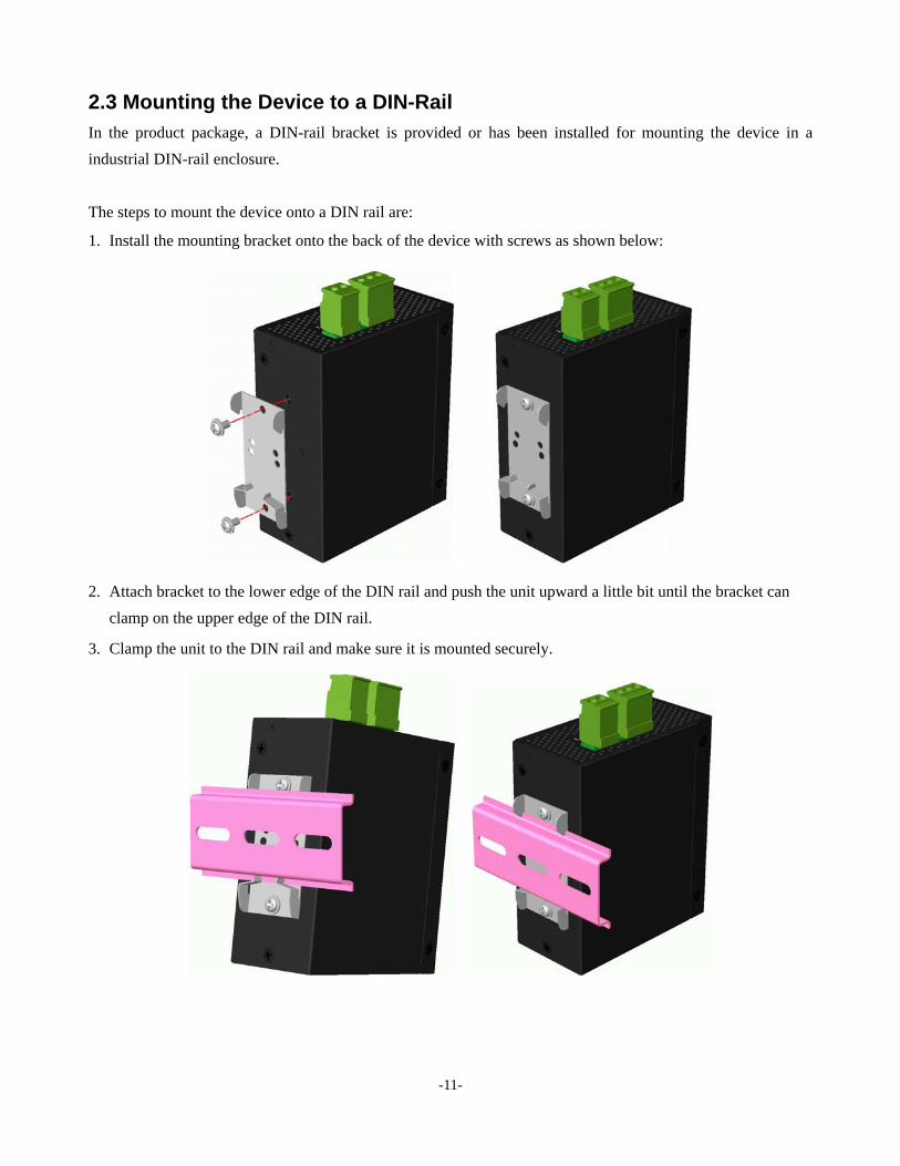
2.3 Mounting the Device to a DIN-Rail
In the product package, a DIN-rail bracket is provided or has been installed for mounting the device in a
industrial DIN-rail enclosure.
The steps to mount the device onto a DIN rail are:
1. Install the mounting bracket onto the back of the device with screws as shown below:
2. Attach bracket to the lower edge of the DIN rail and push the unit upward a little bit until the bracket can
clamp on the upper edge of the DIN rail.
3. Clamp the unit to the DIN rail and make sure it is mounted securely.
-11-

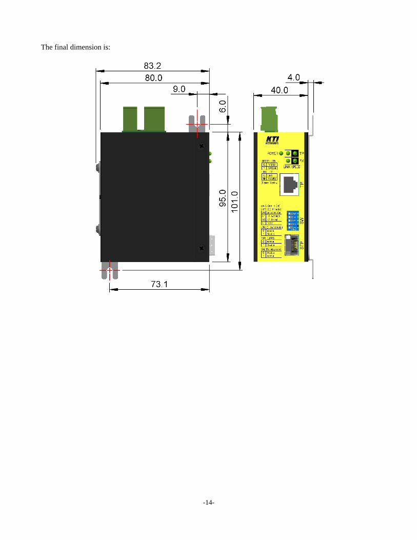
The final dimension is:
-12-

2.4 Mounting the Device on a Panel
The device may be provided optionally with a panel mounting bracket. The bracket supports mounting the
device on a plane surface securely. The mounting steps are:
1. Install the mounting bracket on the device.
2. Screw the bracket on the device.
3. Screw the device on a panel and the locations for screws are shown below:
-13-
The final dimension is:
-14-

2.5 Applying Power
Power pins of the terminal block connector
1 DC Positive () input terminal
2 + DC+ Negative (+) input terminal Pin
3 Reserved
DC+/- Input specifications
Working voltage range: +12V ~ +30VDC
Terminal Plug & Power Wire
A 2P terminal plugs are provided together with the device as shown below:
Power wires: 24 ~ 12AWG (IEC 0.5~2.5mm2)
Wire length: 1 meter max.
-15-

2.6 Alarm Relay Output
Alarm relay output is provided for reporting failure events to a remote alarm relay monitoring system. The
replay output is provided with three contacts on the terminal block connector next DC power interface.
Alarm Relay output pins and logic:
4 5
NO
Alarm relay output, NO (Normal Open) contacts
Normal: Open, Alarm: Shorted
5 6 Pin
NC
Alarm relay output, NC (Normal Close) contacts
Normal: Shorted, Alarm: Open
The relay output can connect relay monitoring system. NO and NC logic are provided individually for selection.
Use the provided 3P terminal plug for signal wiring and plug into the contacts.
Alarm Events
Input power failure
Configured fiber port link fault. (This event can be disabled via DIP SW5 setting. Refer to next section
for DIP SW configuration.)
Note:
Be sure the voltage applied on the relay contacts is within the specification of 30VDC/1A max. or
120VAC/0.5A max.
-16-

2.7 DIP SW Configuration
The configuration DIP SW (setting switches) is used for setting operation configuration manually. Any change
of DIP SW settings takes effect immediately.
The functions of each DIP SW states are:
SW1 SW2 SW3 SW4 SW5 Function
OFF OFF FX port operating mode:
Auto-detection for the type of the SFP fiber transceiver module installed in slot
> 1000BASE-X type - 1Gbps, Full duplex, Auto-negotiation enabled
> 100BASE-FX type - 100Mbps, Full duplex, Forced
> Unknown type - 1Gbps, Full duplex, Auto-negotiation enabled
OFF ON FX port operating mode: 1Gbps, Full duplex, Auto-negotiation enabled
ON OFF FX port operating mode: 1Gbps, Full duplex, Forced (Auto-negotiation disabled)
ON ON FX port operating mode: 100Mbps Full duplex, Forced (Auto-negotiation disabled)
OFF Enable Flow Control
ON Disabled Flow Control
OFF Enable LFPT function (Refer to section 4.2.)
ON Disable LFPT function
OFF Disable FX port link fault relay alarm
ON Enable FX port link fault relay alarm
Note: Factory default settings: blue background
-17-
3. Making LAN Connections
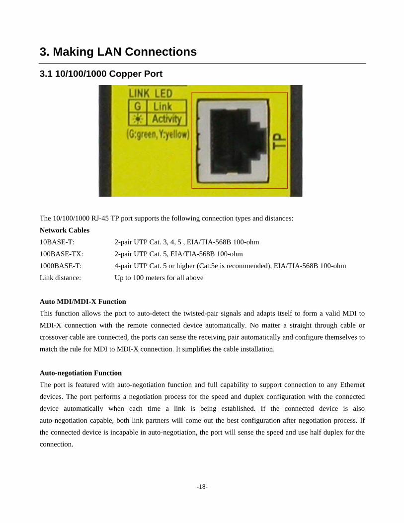
3.1 10/100/1000 Copper Port
The 10/100/1000 RJ-45 TP port supports the following connection types and distances:
Network Cables
10BASE-T: 2-pair UTP Cat. 3, 4, 5 , EIA/TIA-568B 100-ohm
100BASE-TX: 2-pair UTP Cat. 5, EIA/TIA-568B 100-ohm
1000BASE-T: 4-pair UTP Cat. 5 or higher (Cat.5e is recommended), EIA/TIA-568B 100-ohm
Link distance: Up to 100 meters for all above
Auto MDI/MDI-X Function
This function allows the port to auto-detect the twisted-pair signals and adapts itself to form a valid MDI to
MDI-X connection with the remote connected device automatically. No matter a straight through cable or
crossover cable are connected, the ports can sense the receiving pair automatically and configure themselves to
match the rule for MDI to MDI-X connection. It simplifies the cable installation.
Auto-negotiation Function
The port is featured with auto-negotiation function and full capability to support connection to any Ethernet
devices. The port performs a negotiation process for the speed and duplex configuration with the connected
device automatically when each time a link is being established. If the connected device is also
auto-negotiation capable, both link partners will come out the best configuration after negotiation process. If
the connected device is incapable in auto-negotiation, the port will sense the speed and use half duplex for the
connection.
-18-

3.2 Making Fiber Connection
The SFP slot (FX port) must be installed with an SFP fiber transceiver for making fiber connection. Your
device may come with an SFP transceiver pre-installed when it was shipped.
Installing SFP Fiber Transceiver
To install an SFP fiber transceiver into SFP slot, the steps are:
1. Turn off the power to the device unit.
2. Insert the SFP fiber transceiver into the SFP slot. Normally, a bail is provided for every SFP transceiver.
Hold the bail and make insertion.
3. Until the SFP transceiver is seated securely in the slot, place the bail in lock position.
Dual Speed Support
The SFP slot supports 1000BASE-X based SFP fiber transceivers and 100BASE-FX based SFP fiber
transceivers. Refer to Section 2.7 DIP SW Configuration for FX port operating mode setting.
-19-
Connecting Fiber Cables
LC connectors are commonly equipped on most SFP transceiver modules. Identify TX and RX connector
before making cable connection. The following figure illustrates a connection example between two fiber
ports:
Make sure the Rx-to-Tx connection rule is followed on the both ends of the fiber cable.
Network Cables
Multimode (MMF) - 50/125, 62.5/125
Single mode (SMF) - 9/125
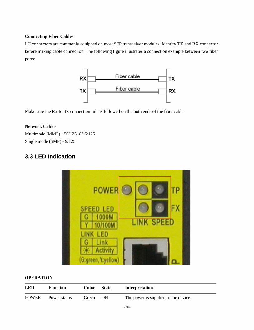
3.3 LED Indication
OPERATION
LED Function Color State Interpretation
POWER Power status Green ON The power is supplied to the device.
-20-

-21-
OFF The power is not supplied to the device.
TP SPEED Port speed status Green ON TP port is running on speed 1Gbps (1000Mbps)
Yellow ON TP port is running on speed 100Mbps or 10Mbps
TP LINK Port link status Green ON TP Port link is established.
Green BLINK TP Port link is up and there is traffic.
OFF TP Port link is down.
FX SPEED Port speed status Green ON FX port is running on speed 1Gbps (1000Mbps)
Yellow ON FX port is running on speed 100Mbps
FX LINK Port link status Green ON FX Port link is established.
Green BLINK FX Port link is up and there is traffic.
OFF FX Port link is down.
POWER-UP
LED Color & State Interpretation
2 SPEED LEDs Quick blinking Device initialization
All 4 LEDs Green ON -> Yellow ON -> OFF Device initialization finished with normal result
2 SPEED LEDs Slow blinking Device initialization finished with error result

4. Functions
This chapter describes some advanced functions provided by the media converter.
4.1 Converter Function
Media Conversion
The device supports the following data conversions between fiber cable and twisted-pair Cat.5 (copper) cable:
The data rate on twisted-pair segment depends on the link speed finally established with the link partner.
Application Notes
1. The media converter supports data conversion of the following packet types:
- Untagged packets
- 802.1Q tagged packets
- Jumbo packets up to 9.6K size
2. The packet data will not be modified after conversion.
3. The packet conversion is performed at full wire speed.
4.2 Link Fault Pass Through Function
When the Link Fault Pass Through (LFPT) function is enabled and the media converter detects a link fault on
one port segment, it will force the other port segment link down. It looks like that a link fault is passed from
one port to the other.
The following example illustrates a link fault occurs on the fiber cable (any one cable in a duplex fiber
connection). The link fault is forwarded to both copper link partners finally by LFPT operation of two media
converters.
-22-

Both Ethernet devices will also detect a link fault on each Cat.5 connection, although the real fault occurs on
the fiber connection exactly.
The following example illustrates a real link fault occurs on one Cat.5 and the link fault is passed to the other
Cat.5 over two converters and the fiber cable by LFPT operation. Finally, the other link partner also detects a
link fault.
Advantage
The function allows two remote link partners of the media converters detect the link fault finally no matter
where the exact fault occurs. It allows the upper application takes necessary action in case a real link fault
occurs in any cable segment.
Methods to enable the function
The LFPT function can be enabled by setting DIP SW4 at “OFF” position.
-23-