key sensor technology components: hardware and software ... · key sensor technology components:...
TRANSCRIPT
51
Chapter 3
Key Sensor Technology Components: Hardware and Software Overview
Sensors measure a variety of chemical, biological, and physical quantities using a wide range of sensing techniques as outlined in the previous chapter. The action of sensing creates an output signal, via a transduction process, that must be processed and transmitted in some manner in order for a person or another device to do something useful with it. Sensors that have the capability to acquire, process, and output measurements over a data bus in a single package are referred to as smart sensors. The capabilities of these smart sensors can be further augmented with features, such as radio communications, sampling, remote manageability, and enclosures, to deliver smart sensor systems. The combination of hardware and software enables signal conditioning, data processing, transmission, storage, and display of the sensor measurement. In this chapter, we will examine the key hardware and software features that are important in the design of sensors and sensor systems.
Smart SensorsThe difference between a smart sensor and a sensor system isn’t always clear. Smart sensors are generally expected to incorporate sensing and transduction functions with an analog interface circuit, a microcontroller with an integrated analog-to-digital converter (ADC), and an input/output (I/O) bus interface in a single integrated package (Huijsing, 2008). Apart from the system requirements, smart sensors are also functionally expected to have features such as auto-calibration, compensated measurements (baseline drift adjustment, environmental variation correction—for example, temperature) and self-health evaluation. In addition, smart sensors may have firmware-based signal processing capabilities, processed data validation, and multisensing capabilities (Mathas, 2011). Many smart sensor features are driven primarily by the use of a modern microcontroller (MCU). The inclusion of an MCU in a smart sensor enables digital signal processing (DSP), ADC, baseline correction, data processing, data storage support, power management, and interfacing functions such as external communications.
Smart sensors normally have their components integrated onto the same printed circuit board (PCB). This level of integration improves both reliability and performance, while reducing production testing costs. The small form factor also enables flexibility in terms of platform design, which can be important for applications such as on-body vital signs monitoring. However, upfront development costs can be significant, and high volumes are often required to make smart sensors economical. Due to the small footprint of PCBs, designers must carefully consider board layout effects on the sensor’s operational performance. Issues such as local heating effects and radio frequency (RF) interference need to be considered to avoid any influence on sensor performance.
The market for smart sensors is likely to increase to USD 6.7 billion by 2017, as advances in microelectromechanical systems (MEMS) fabrication techniques drive down sensor manufacturing costs (PRWeb, 2012). As the dimensions of smart sensors continue to decrease, new applications are sure to emerge, such as implantable biosensors (Córcoles et al., 2013).
Chapter 3 ■ Key SenSor teChnology ComponentS: hardware and Software overview
52
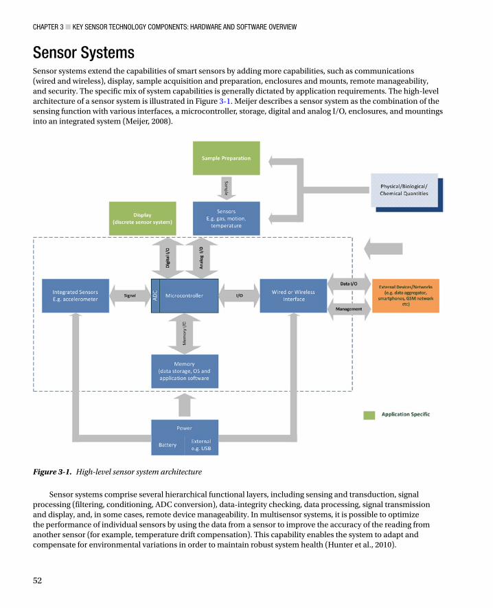
Sensor SystemsSensor systems extend the capabilities of smart sensors by adding more capabilities, such as communications (wired and wireless), display, sample acquisition and preparation, enclosures and mounts, remote manageability, and security. The specific mix of system capabilities is generally dictated by application requirements. The high-level architecture of a sensor system is illustrated in Figure 3-1. Meijer describes a sensor system as the combination of the sensing function with various interfaces, a microcontroller, storage, digital and analog I/O, enclosures, and mountings into an integrated system (Meijer, 2008).
Figure 3-1. High-level sensor system architecture
Sensor systems comprise several hierarchical functional layers, including sensing and transduction, signal processing (filtering, conditioning, ADC conversion), data-integrity checking, data processing, signal transmission and display, and, in some cases, remote device manageability. In multisensor systems, it is possible to optimize the performance of individual sensors by using the data from a sensor to improve the accuracy of the reading from another sensor (for example, temperature drift compensation). This capability enables the system to adapt and compensate for environmental variations in order to maintain robust system health (Hunter et al., 2010).
Chapter 3 ■ Key SenSor teChnology ComponentS: hardware and Software overview
53
For some application domains, such as healthcare, the physical attributes of a sensor system are important selection criteria, particularly for body-worn configurations. These attributes include weight, physical dimensions, enclosure type, sensor-mounting system, ability to wipe down, and waterproofing (that is, preventing biological fluid ingress). The weight of the sensor system is also important for mobile applications, such as those for smartphones, or in vibration applications, where the weight of the sensor could directly impact the accuracy of the measurement (Pecht, 2008).
Sensor PlatformsSensor platforms are a subset of smart sensors. Like smart sensors, they feature a microcontroller, a wired/wireless interface, and memory. However, sensor platforms are designed for non-specific applications. They have the functionality to integrate with unspecified external sensors, and an interface for programming the microcontroller to perform a specific function. These platforms are very useful for rapid prototyping—sensor hardware and actuators can be physically or wirelessly connected to the platform’s sensor interface (digital or analog). Most sensor platforms are accompanied by an integrated development environment (IDE) and sample application code that can be combined to program the sensors or actuators. If the prototype is successful, it can form the basis of a specific smart sensor design. If not, the sensors can be quickly reconfigured and retested, or they can be discarded and the platform reused for a different application. However, this flexibility has some drawbacks: sensor platforms are physically larger and more expensive than smart sensors, and the user may not require all of the features available on the sensor platform.
Sensor platforms are very popular among hobbyists, designers, researchers, and educators. Many sensor platforms exist, including Parallax Basic Stamp, Netmedia’s BX-24, Phidgets, and MIT’s Handyboard. The most common sensor platforms in the health, wellness, and environmental domains are Arduino, Shimmer, and smartphones.
The Arduino I/O BoardThe Arduino (www.arduino.cc) was developed in Italy in 2005 to allow non-experts, including artists, designers, and hobbyists, to rapidly create interactive prototypes. The Arduino I/O board is commonly referred to as “an Arduino.” However, the term “Arduino” describes not only the open source hardware sensor platform, but also open source software and the active user community.
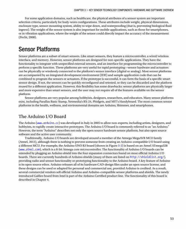
Traditionally, Arduino I/O boards are developed around a member of the Atmega MegaAVR MCU family (Atmel, 2013), although there is nothing to prevent someone from creating an Arduino-compatible I/O board using a different MCU. For example, the Arduino UNO R3 board (shown in Figure 3-2) is based on an Atmel ATmega328 (www.atmel.com), which is a 8-bit Atmega core microcontroller. The functionality of Arduino I/O boards can be extended by plugging an Arduino shield into the four expansion connectors found on most official Arduino I/O boards. There are currently hundreds of Arduino shields (many of them are listed on http://shieldlist.org/), providing radio and sensor functionality or prototyping functionality to the Arduino board. A key feature of Arduino is its open source ethos. Arduino releases all of its hardware CAD-design files under an open source license, and these designs can be used or adapted for personal and commercial use, provided Arduino is credited. As a result, several commercial vendors sell official Arduino and Arduino-compatible sensor platforms and shields. The newly introduced Galileo board from Intel is part of the Arduino Certified product line. The functionality of this board is described in Chapter 4.
Chapter 3 ■ Key SenSor teChnology ComponentS: hardware and Software overview
54
The Arduino I/O board MCU is programmed using the open source Arduino programming language (an implementation of the Wiring programming language) and the open source Arduino IDE (based on the Processing IDE). It can also be programmed using Atmel’s AVR-studio or other software environments.
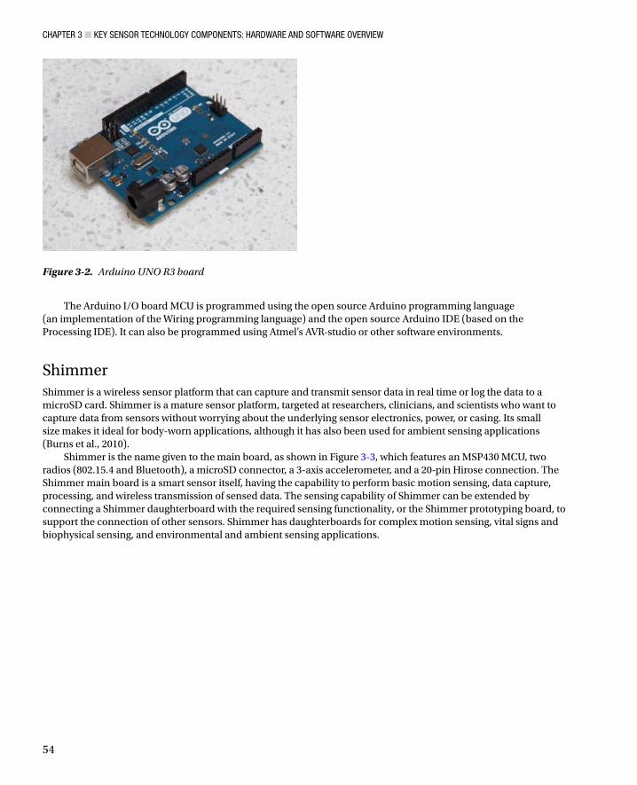
ShimmerShimmer is a wireless sensor platform that can capture and transmit sensor data in real time or log the data to a microSD card. Shimmer is a mature sensor platform, targeted at researchers, clinicians, and scientists who want to capture data from sensors without worrying about the underlying sensor electronics, power, or casing. Its small size makes it ideal for body-worn applications, although it has also been used for ambient sensing applications (Burns et al., 2010).
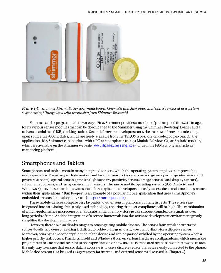
Shimmer is the name given to the main board, as shown in Figure 3-3, which features an MSP430 MCU, two radios (802.15.4 and Bluetooth), a microSD connector, a 3-axis accelerometer, and a 20-pin Hirose connection. The Shimmer main board is a smart sensor itself, having the capability to perform basic motion sensing, data capture, processing, and wireless transmission of sensed data. The sensing capability of Shimmer can be extended by connecting a Shimmer daughterboard with the required sensing functionality, or the Shimmer prototyping board, to support the connection of other sensors. Shimmer has daughterboards for complex motion sensing, vital signs and biophysical sensing, and environmental and ambient sensing applications.
Figure 3-2. Arduino UNO R3 board
Chapter 3 ■ Key SenSor teChnology ComponentS: hardware and Software overview
55
Shimmer can be programmed in two ways. First, Shimmer provides a number of precompiled firmware images for its various sensor modules that can be downloaded to the Shimmer using the Shimmer Bootstrap Loader and a universal serial bus (USB) docking station. Second, firmware developers can write their own firmware code using open source TinyOS modules, which are freely available from the TinyOS repository on code.google.com. On the application side, Shimmer can interface with a PC or smartphone using a Matlab, Labview, C#, or Android module, which are available on the Shimmer web site (www.shimmersensing.com); or with the PAMSys physical activity monitoring platform.
Smartphones and TabletsSmartphones and tablets contain many integrated sensors, which the operating system employs to improve the user experience. These may include motion and location sensors (accelerometers, gyroscopes, magnetometers, and pressure sensors), optical sensors (ambient light sensors, proximity sensors, image sensors, and display sensors), silicon microphones, and many environment sensors. The major mobile operating systems (iOS, Android, and Windows 8) provide sensor frameworks that allow application developers to easily access these real time data streams within their applications. “Run Keeper” is an example of a popular mobile application that uses a smartphone’s embedded sensors for an alternative use (http://runkeeper.com).
These mobile devices compare very favorably to other sensor platforms in many aspects. The sensors are integrated into an existing, frequently used technology, ensuring that user compliance will be high. The combination of a high-performance microcontroller and substantial memory storage can support complex data analysis over long periods of time. And the integration of a sensor framework into the software development environment greatly simplifies the development process.
However, there are also disadvantages to sensing using mobile devices. The sensor framework abstracts the sensor details and control, making it difficult to achieve the granularity you can realize with a discrete sensor. Moreover, sensing is a secondary function of the device and can be paused or killed by the operating system when a higher priority task occurs. Finally, Android and Windows 8 run on various hardware configurations, which means the programmer has no control over the sensor specification or how its data is translated by the sensor framework. In fact, the only way to ensure that sensor data is accurate is to use a discrete sensor that is wirelessly connected to the phone. Mobile devices can also be used as aggregators for internal and external sensors (discussed in Chapter 4).
Figure 3-3. Shimmer Kinematic Sensors (main board, kinematic daughter board,and battery enclosed in a custom sensor casing) (image used with permission from Shimmer Research)
Chapter 3 ■ Key SenSor teChnology ComponentS: hardware and Software overview
56
Microcontrollers for Smart SensorsWe have already defined a smart sensor as sensing capabilities combined with computing, I/O, and communications in a single, integrated package. Many smart-sensor features are driven primarily by an MCU, which includes ADC, data storage support, power management, and interfacing functions such as external communications. We now look in detail at the key architectural components of a modern MCU, and at how they enable smart sensors.
The terms “microprocessor,” “microcomputer,” and “microcontroller” are often confused, but they have very different and distinct meanings. A microprocessor is a central processing unit (CPU), implemented on a single chip. In fact, the “micro” in “microprocessor” refers to this single-chip implementation. Prior to 1970, CPUs were not integrated on a single chip and consisted of many chips or many discrete devices connected together.
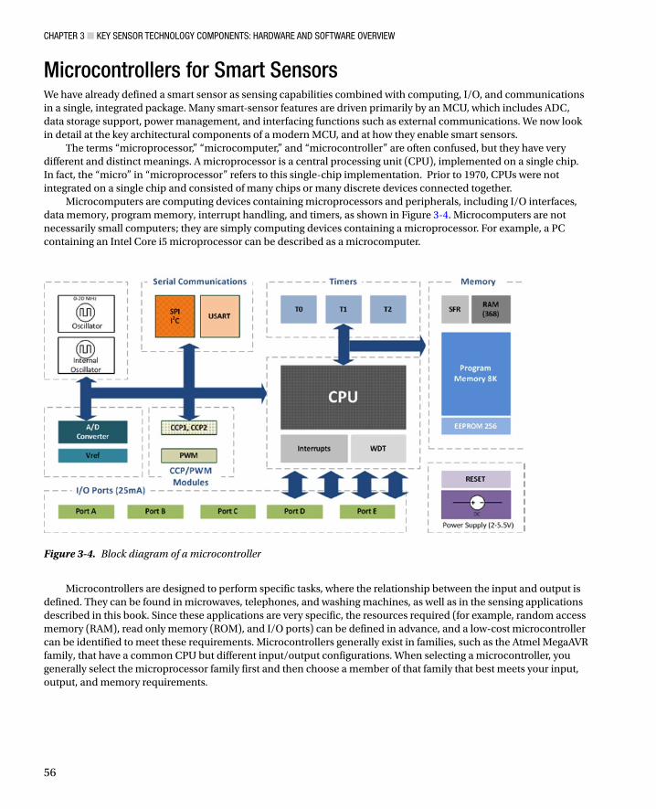
Microcomputers are computing devices containing microprocessors and peripherals, including I/O interfaces, data memory, program memory, interrupt handling, and timers, as shown in Figure 3-4. Microcomputers are not necessarily small computers; they are simply computing devices containing a microprocessor. For example, a PC containing an Intel Core i5 microprocessor can be described as a microcomputer.
Figure 3-4. Block diagram of a microcontroller
Microcontrollers are designed to perform specific tasks, where the relationship between the input and output is defined. They can be found in microwaves, telephones, and washing machines, as well as in the sensing applications described in this book. Since these applications are very specific, the resources required (for example, random access memory (RAM), read only memory (ROM), and I/O ports) can be defined in advance, and a low-cost microcontroller can be identified to meet these requirements. Microcontrollers generally exist in families, such as the Atmel MegaAVR family, that have a common CPU but different input/output configurations. When selecting a microcontroller, you generally select the microprocessor family first and then choose a member of that family that best meets your input, output, and memory requirements.
Chapter 3 ■ Key SenSor teChnology ComponentS: hardware and Software overview
57
CPUs CPU design is a broad and complex topic that is beyond the scope of this text. However, this section provides a brief overview of CPUs and the terms used to describe them in the context of microcontrollers.
A CPU, at its most basic level, consists of five parts:
• Arithmetic and logic unit (ALU): The ALU is responsible for performing calculations on data. A basic CPU might contain just one ALU that can perform only addition, subtraction, and basic logic. More sophisticated CPUs may contain several ALUs that are capable of advanced floating point operations. When the internal bus in an MCU is a 16-bit bus and the ALU performs operations on 16 bits at an instruction level, the MCU is described as a 16-bit microcontroller. A 16-bit MCU provides greater precision and performance than an 8-bit MCU, but less than a 32-bit MCU.
• Control unit (CU): The CU controls the movement of instructions in and out of the processor, as well as the operation of the ALU.
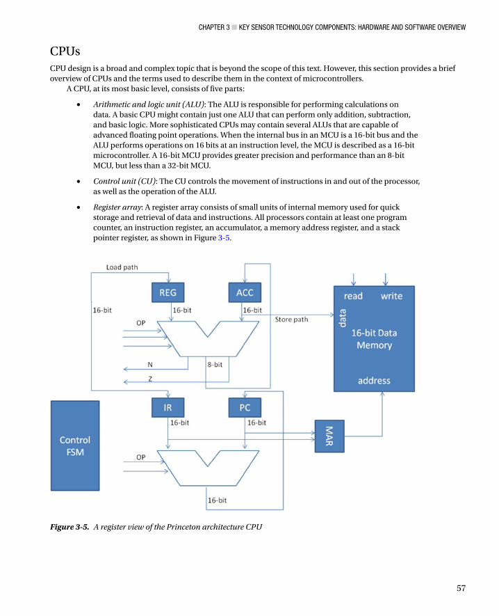
• Register array: A register array consists of small units of internal memory used for quick storage and retrieval of data and instructions. All processors contain at least one program counter, an instruction register, an accumulator, a memory address register, and a stack pointer register, as shown in Figure 3-5.
Figure 3-5. A register view of the Princeton architecture CPU
Chapter 3 ■ Key SenSor teChnology ComponentS: hardware and Software overview
58
• System bus: The system bus comprises a data bus, an address bus, and a control bus and is used to transfer data between the processor, memory, and peripherals. The address bus carries the address of a specified location. If an address bus has n address lines, it can access 2n locations. For example, a 16-bit address bus can access 216 = 65,536 locations (or 64K memory). The data bus carries information between the CPU and memory, or between the CPU and I/O devices. The control bus carries commands from the CPU and returns status signals from the devices.
• Memory: Although not actually part of the CPU, memory is an essential part of CPU operation as it stores data and the program being executed.
The instruction set architecture (ISA) describes a list of instructions that a processor understands. Different processors have different instruction sets, which are optimized for the features of that processor. Each instruction consists of a short code, called an opcode, describing the operation the CPU is expected to perform; and an operand, describing where the data required for the operation can be found. Programmers almost never write their programs using this instruction set, but their code is translated into this form at some point before execution so the CPU can manipulate it.
Processors are generally described as having either a reduced instruction set computer (RISC) or a complex instruction set computer (CISC) architecture. RISC describes a simple instruction set in which instructions have fixed length and are implemented in a single cycle using distinct hardwired control. RISC architecture includes many registers, reducing the need for external fetches from memory. RISC processors have a simpler design than CISC, with smaller chips, smaller pin counts, and very low power consumption. RISC is a cheaper architecture to produce.
CISC has a larger instruction set, featuring varying code lengths, varying execution times, and a complex architecture. CISC allows memory access during ALU and data transfer instructions. Many CISC architecture instructions are macro-like, allowing a programmer to use one instruction in place of several simpler instructions. The differences between RISC and CISC have become less dramatic as both architectures have borrowed features from each other. Modern microcontrollers typically have a RISC core but are capable of running some CISC features by using on-chip compilers.
RegistersRegisters are small RAM memory elements, 1–2 bytes in size. There are two types of registers: general purpose and special function. General purpose registers are used by the ALU to store interim calculation results because they can be accessed faster than external memory. Special function registers (SFRs) are registers whose function is defined by the manufacturer. The bits of these registers are connected directly to internal circuits, including the ADC and universal synchronous/asynchronous receiver/transmitter (USART), giving them direct control of these circuits. SFR registers and their bits can be called by name in software.
MemoryA microcontroller contains three types of memory: RAM, ROM, and electrically erasable programmable read-only memory (EEPROM), all of which are connected to the CPU via the address bus.
RAM stores data that can be changed during program execution. The data contained in RAM •is usually lost when the microcontroller is switched off; therefore, RAM should not be used to store programs or settings that must be saved between power cycles.
ROM is non-volatile data memory, meaning it does not lose its data when powered off. For this •reason, it is used to store program and permanent data and is often called “program memory.” Several different technologies are used to implement ROM in an MCU, including EEPROM and flash memory.
EEPROM can be electrically erased and rewritten, negating the need for physical removal. •EEPROM memory uses NOR gates to support fast access time and byte-level erasure. But it is more expensive than other erasable forms of memory, such as flash.
Chapter 3 ■ Key SenSor teChnology ComponentS: hardware and Software overview
59
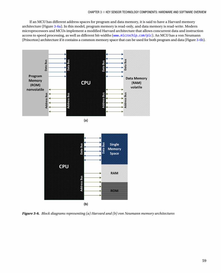
If an MCU has different address spaces for program and data memory, it is said to have a Harvard memory architecture (Figure 3-6a). In this model, program memory is read-only, and data memory is read-write. Modern microprocessors and MCUs implement a modified Harvard architecture that allows concurrent data and instruction access to speed processing, as well as different bit-widths (www.microchip.com/pic). An MCU has a von Neumann (Princeton) architecture if it contains a common memory space that can be used for both program and data (Figure 3-6b).
Figure 3-6. Block diagrams representing (a) Harvard and (b) von Neumann memory architectures
Chapter 3 ■ Key SenSor teChnology ComponentS: hardware and Software overview
60
Timers and CountersMost microcontrollers have one or more built-in timers that can be used to generate precise time delays by counting fixed intervals of time or occurrences of an event. A timer can also act as a real-time clock by generating repeated interrupts at regular intervals that can be used to initiate events:
• Oscillators: Microcontrollers use quartz crystal oscillators to generate precise, stable time pulses. A timer counts the number of pulses generated by the oscillator to generate a time signal.
• Timers: Functionally, a timer is an 8- or 16-bit SFR that is automatically incremented by each incoming pulse. A timer that counts the pulses of the internal quartz oscillator to measure time between two events is called a timer; a timer that counts pulses from an external source is called a counter. An 8-bit timer can only count to 255; a 16-bit timer can count to 65,535. The timer is automatically reset and counting restarts when the limit is exceeded; this is known as overflow. An interrupt can be generated to notify the user each time the timer overflows. The timer prescaler reduces the number of pulses supplied to the timer to slow the speed of the timer. The timer postscaler adjusts how often the timer interrupt is called but doesn’t affect the timer itself. Both the timer prescaler and postscaler can be modified using the relevant SFRs.
• Interrupts: An interrupt is a call sent to the MCU to stop the normal execution of a program so the MCU can do something else. An interrupt service routine (ISR) is a piece of code that the MCU starts on receipt of a specific interrupt. When the ISR has completed, the MCU returns to whatever it was doing before the interrupt was received. There are several sources for interrupts, both hardware and software. Common hardware interrupts are raised when the timer counter overflows, data is received on the serial port, or an external interrupt pin is brought high. The processor can also interrupt itself if a procedure is called during normal execution of a program. Non-critical interrupts can be disabled, using the Interrupt Enable SFR, but interrupts indicating critical issues, such as a drop in source voltage, can’t be disabled.
• Watchdog timer: The watchdog timer (WDT) is a resistor-capacitor (RC) oscillator-based timer that operates independently of other timers in the MCU. Its function is to ensure that the program does not get trapped in an inconsistent state. If the WDT is enabled, it begins to count. If the WDT counter overflows, the microcontroller program is reset and program execution starts from the first instruction. To avoid WDT resetting your program and affecting program execution, the WDT should be reset at regular intervals within the program code.
Debugging InterfacesMicrocontroller-based embedded systems lack user interfaces, including the keyboards, monitors, and disk drives that are present on computers. Therefore, different methods must be applied to debug hardware and firmware issues. These methods range from illuminating a light-emitting diode (LED) to indicate success or failure to using logic analyzers for monitoring traces on a system bus. Microcontrollers usually provide a hardware interface that can be used to debug microcontroller hardware and software. We’ll briefly describe the hardware interfaces here (Hector, 2002), and debugging methods and software-based debugging later in the chapter.
In-circuit emulators (ICE) are hardware devices that emulate the CPU of the embedded •processor. These devices are connected between the embedded system and a PC and provide a user interface that lets the software developer monitor and control the embedded system. The device normally replaces the system’s MCU with a “pod” and box that emulates the processor being replaced. ICE devices provide complete control of the MCU, and can trace data on the system bus. They are expensive tools, however, and are typically used only by hardware developers.
Chapter 3 ■ Key SenSor teChnology ComponentS: hardware and Software overview
61
In-circuit debuggers (ICD), also called background mode emulators (BME, and are often •mistakenly referred to as ICE), are fundamentally different from ICE devices. ICE devices enable debugging by replacing the device under test with a device that emulates that device, whereas ICD devices use the Joint Test Action Group (JTAG) debug interface on the MCU to debug using the actual device under test. The debugging capabilities of the ICD are dependent on the debug features enabled by the manufacturer for a particular MCU or MCU family. Typically, an ICD allows the developer to step through code actually running in the target MCU, start and stop it, and read the register and processor state. It does not provide trace functionality or the ability to overlay memory that can be found in ICE devices. Because all processors that support ICD have the ICD hardware built in, the only extra cost is the ICD communication hardware (between the PC and the processor/microcontroller). ICDs are typically 3–10 times cheaper than ICEs and are suitable for software developers who use ready-built boards. Processor manufacturers and emulator manufacturers are creating hybrid technologies that provide ICE-like functionality over ICD interfaces.
ROM monitors are the cheapest of the emulator types. They provide debug information to •the development environment on the PC via the universal asynchronous receiver/transmitter (UART) interface. The ROM monitor allows both line-by-line execution and code breakpoints, but it does not offer real-time control. It is not suitable for debugging embedded applications that use a UART because the ROM monitor needs the UART to communicate with the PC.
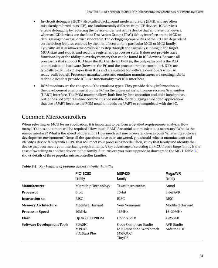
Common MicrocontrollersWhen selecting an MCU for an application, it is important to perform a detailed requirements analysis: How many I/O lines and timers will be required? How much RAM? Are serial communications necessary? What is the sensor interface? What is the speed of operation? How much will one or several devices cost? What is the software development environment? Once all the questions have been answered, you should select a manufacturer and identify a device family with a CPU that will meet your processing needs. Then, study that family and identify the device that best meets your interfacing requirements. A key advantage of selecting an MCU from a large family is the ease of switching to another device in that family if it turns out you must upgrade or downgrade the MCU. Table 3-1 shows details of three popular microcontroller families.
Table 3-1. Key Features of Popular Microcontroller Families
PIC16C5Xfamily
MSP430family
MegaAVRfamily
Manufacturer Microchip Technology Texas Instruments Atmel
Processor 8-bit 16-bit 8-bit AVR
Instruction set RISC RISC RISC
Memory Architecture Modified Harvard Von-Neumann Modified Harvard
Processor Speed 40MHz 16MHz 16–20MHz
Flash Up to 2K EEPROM Up to 512KB 4–256KB
Software Development Tools PBASICMPLABPIC Start Plus
Code Composer StudioIAR Embedded WorkbenchMSPGCC,TinyOS
AVR StudioArduino IDE
Chapter 3 ■ Key SenSor teChnology ComponentS: hardware and Software overview
62
Interfaces and Embedded CommunicationsVarious methods are employed to communicate between subsystems in a sensor system, and from a sensor system to external interfaces. Digital interfaces with lightweight protocols are normally used for subsystem-to-subsystem communications (for example, digital sensor to MCU communication). They are also used to provide bidirectional input and output between the sensor system and larger systems. General purpose input/output (GPIO) pins are commonly found in embedded systems or on chips that have limited pins. As the name suggests, GPIO pins have no specific purpose but can be programmed to act as an input for sensor data or as an output that controls external components, such as LED indicators. Analog interfaces are used to transfer signals between analog sensors, signal conditioning circuitry, and the MCU’s analog interfaces.
In an effort to standardize how smart sensors should be integrated into larger systems, the IEEE developed the 1451 standard, which “describes a set of open, common, network-independent communication interfaces for connecting transducers (sensors or actuators) to microprocessors, instrumentation systems, and control/field networks.” The 1451.4 standard defines the format of the transducer electronic data sheet (TEDS), which holds key information that is unique to a sensor type for a specific manufacturer. A TEDS is typically stored in the sensor’s EEPROM and contains information such as serial numbers, calibration dates, output scaling factors, and baseline offsets. The TEDS smart transducer interface makes it easier for transducer manufacturers to develop smart devices that can interface to networks, systems, and instruments using existing and emerging sensor and networking technologies. The standard does not specify interfaces or define physical connections. However, standard wired interfaces such as USB and Ethernet, and wireless such as 802.15.4, 802.11, and 6LoWPAN are suitable (Lee, 2005).
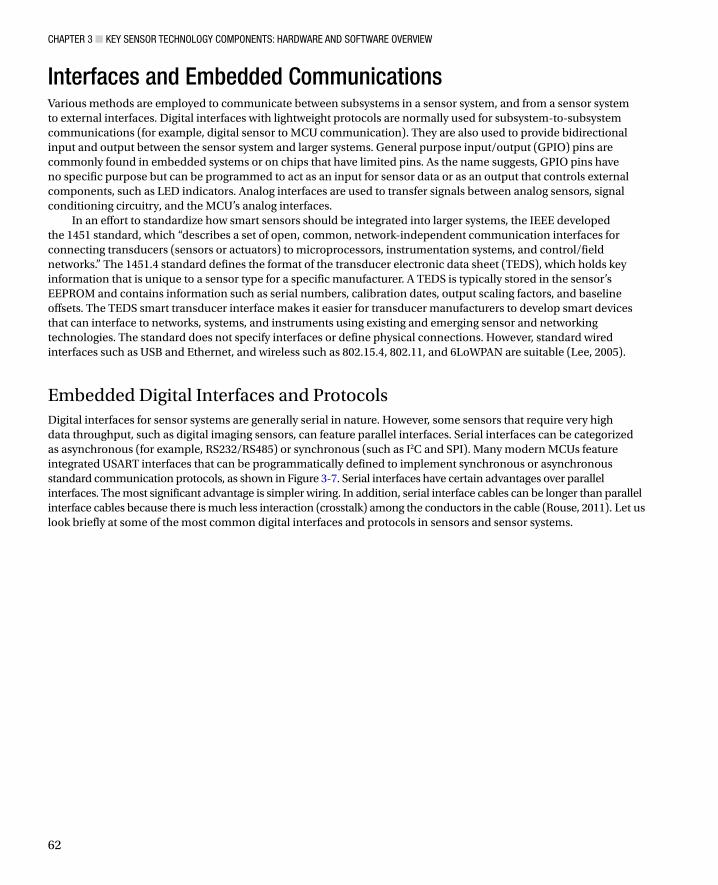
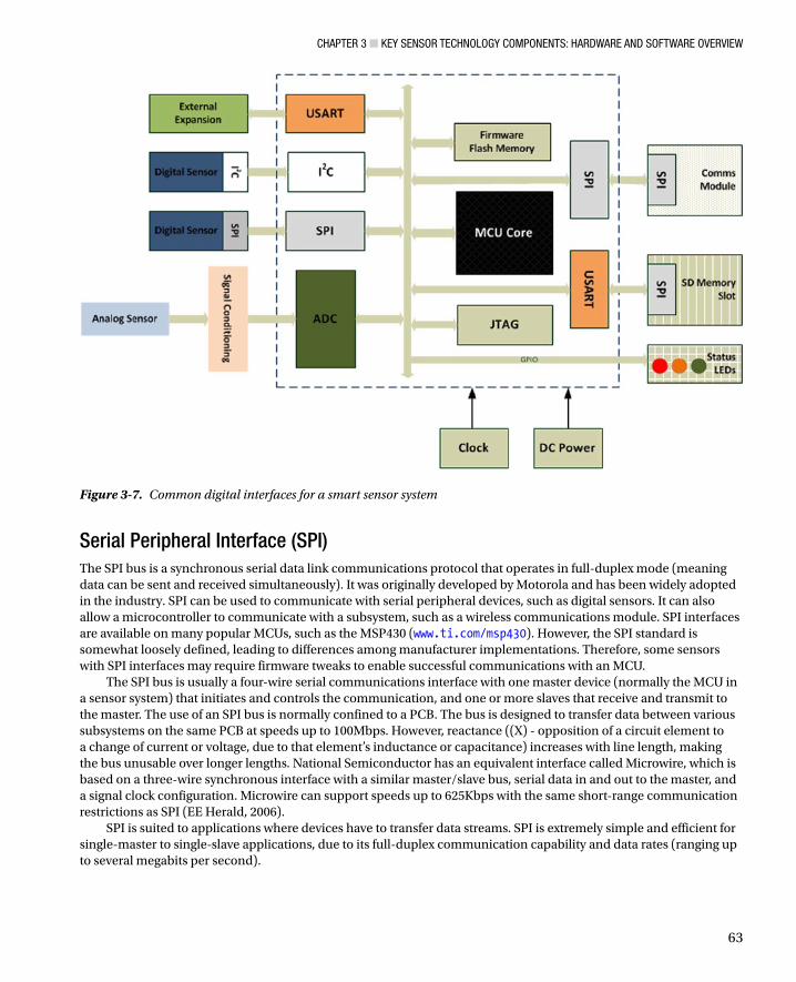
Embedded Digital Interfaces and ProtocolsDigital interfaces for sensor systems are generally serial in nature. However, some sensors that require very high data throughput, such as digital imaging sensors, can feature parallel interfaces. Serial interfaces can be categorized as asynchronous (for example, RS232/RS485) or synchronous (such as I2C and SPI). Many modern MCUs feature integrated USART interfaces that can be programmatically defined to implement synchronous or asynchronous standard communication protocols, as shown in Figure 3-7. Serial interfaces have certain advantages over parallel interfaces. The most significant advantage is simpler wiring. In addition, serial interface cables can be longer than parallel interface cables because there is much less interaction (crosstalk) among the conductors in the cable (Rouse, 2011). Let us look briefly at some of the most common digital interfaces and protocols in sensors and sensor systems.
Chapter 3 ■ Key SenSor teChnology ComponentS: hardware and Software overview
63
Serial Peripheral Interface (SPI)The SPI bus is a synchronous serial data link communications protocol that operates in full-duplex mode (meaning data can be sent and received simultaneously). It was originally developed by Motorola and has been widely adopted in the industry. SPI can be used to communicate with serial peripheral devices, such as digital sensors. It can also allow a microcontroller to communicate with a subsystem, such as a wireless communications module. SPI interfaces are available on many popular MCUs, such as the MSP430 (www.ti.com/msp430). However, the SPI standard is somewhat loosely defined, leading to differences among manufacturer implementations. Therefore, some sensors with SPI interfaces may require firmware tweaks to enable successful communications with an MCU.
The SPI bus is usually a four-wire serial communications interface with one master device (normally the MCU in a sensor system) that initiates and controls the communication, and one or more slaves that receive and transmit to the master. The use of an SPI bus is normally confined to a PCB. The bus is designed to transfer data between various subsystems on the same PCB at speeds up to 100Mbps. However, reactance ((X) - opposition of a circuit element to a change of current or voltage, due to that element’s inductance or capacitance) increases with line length, making the bus unusable over longer lengths. National Semiconductor has an equivalent interface called Microwire, which is based on a three-wire synchronous interface with a similar master/slave bus, serial data in and out to the master, and a signal clock configuration. Microwire can support speeds up to 625Kbps with the same short-range communication restrictions as SPI (EE Herald, 2006).
SPI is suited to applications where devices have to transfer data streams. SPI is extremely simple and efficient for single-master to single-slave applications, due to its full-duplex communication capability and data rates (ranging up to several megabits per second).
Figure 3-7. Common digital interfaces for a smart sensor system
Chapter 3 ■ Key SenSor teChnology ComponentS: hardware and Software overview
64
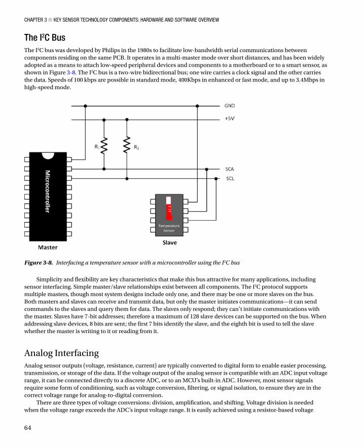
The I2C BusThe I2C bus was developed by Philips in the 1980s to facilitate low-bandwidth serial communications between components residing on the same PCB. It operates in a multi-master mode over short distances, and has been widely adopted as a means to attach low-speed peripheral devices and components to a motherboard or to a smart sensor, as shown in Figure 3-8. The I2C bus is a two-wire bidirectional bus; one wire carries a clock signal and the other carries the data. Speeds of 100 kbps are possible in standard mode, 400Kbps in enhanced or fast mode, and up to 3.4Mbps in high-speed mode.
Figure 3-8. Interfacing a temperature sensor with a microcontroller using the I2C bus
Simplicity and flexibility are key characteristics that make this bus attractive for many applications, including sensor interfacing. Simple master/slave relationships exist between all components. The I2C protocol supports multiple masters, though most system designs include only one, and there may be one or more slaves on the bus. Both masters and slaves can receive and transmit data, but only the master initiates communications—it can send commands to the slaves and query them for data. The slaves only respond; they can’t initiate communications with the master. Slaves have 7-bit addresses; therefore a maximum of 128 slave devices can be supported on the bus. When addressing slave devices, 8 bits are sent; the first 7 bits identify the slave, and the eighth bit is used to tell the slave whether the master is writing to it or reading from it.
Analog InterfacingAnalog sensor outputs (voltage, resistance, current) are typically converted to digital form to enable easier processing, transmission, or storage of the data. If the voltage output of the analog sensor is compatible with an ADC input voltage range, it can be connected directly to a discrete ADC, or to an MCU’s built-in ADC. However, most sensor signals require some form of conditioning, such as voltage conversion, filtering, or signal isolation, to ensure they are in the correct voltage range for analog-to-digital conversion.
There are three types of voltage conversions: division, amplification, and shifting. Voltage division is needed when the voltage range exceeds the ADC’s input voltage range. It is easily achieved using a resistor-based voltage
Chapter 3 ■ Key SenSor teChnology ComponentS: hardware and Software overview
65
divider circuit. Voltage amplification is required for sensors that create small voltages, such as accelerometers. The output voltage is multiplied using an op-amp-based circuit to increase the range and sensitivity of the circuit. The ratio of signal output to signal input following linear amplification is commonly known as gain. Care must be taken in selecting the correct gain to ensure that the amplified output does not exceed the input range of the ADC, which would cause signal saturation. If the amplified sensor output voltage falls beneath the minimum input voltage to the ADC, the sensor output must be shifted to the ADC’s minimum input. A summing circuit, based on op-amps, is typically used to achieve voltage shifting. A common example of analog signal conditioning is using a Wheatstone bridge to convert impedance measurements from a sensor, such as a strain gauge, into voltages (see mechanical sensors, Chapter 2) that can be further amplified to increase the sensitivity of the sensor reading.
The frequency response of the amplifier can be stabilized at low frequencies through the addition of a capacitive element. However, the signal characteristics should be fully understood beforehand to ensure that appropriate sensor response times are used (Bates, 2006). Filtering the sensor signal limits the frequency range and removes noise from the signal, allowing the signal of interest to be measured more accurately. The frequency range removed is determined by the type of filter—low-pass, high-pass, or band-pass. If a sensor has a slow response time, a low-pass filter can be used to remove high-frequency signals. Inversely, if the response is high frequency, then low-frequency signals can be removed. Noise at an AC electrical frequency is typically removed using a notch filter to eliminate signals in the 50–60 Hz range. Keep in mind that filters should be carefully selected to ensure that no useful information is removed. For example, valuable information that may exist in higher frequency harmonics of the fundamental frequency will be lost if a low-pass filter is used at the fundamental frequency. It is therefore of critical importance to fully characterize the sensor signal before designing the filtering regime.
In healthcare applications, where there may be direct contact between a patient’s body and the sensor, signal isolation between the source and the measurement and conversion circuits is an important safety consideration. Isolation amplifiers should be used to ensure there is no direct electrical connection with the measurement. This provides a safeguard against the possibility of dangerous voltages or currents passing into the sensor, preventing damage or potential injury to the patient. The inverse case is also applicable to ensure that damaging signals are not passed from the sensing environment into the measurement circuits (Kester, 2005).
Sensor CommunicationsA sensor’s ability to communicate its results to a person or another device is fundamental to its usefulness. There are three main ways in which a sensor communicates: it can display data directly to the user, transfer data over a wired interface, or transfer data wirelessly.
Sensors can communicate binary status information, such as power on or off, using a light-emitting diode (LED). Single-use discrete sensors, such as pregnancy-testing kits, can communicate using a color-changing indicator or a simple, inexpensive liquid-crystal display (LCD). As the complexity of the data from the sensor increases, larger and more complex LCD screens may be required. LCD screens can display characters, symbols, or graphics. They range in size, price, and configuration, from showing just a couple of lines to large displays. Single-application LCDs display only predefined graphics, whereas large displays, such as those for weather stations and home heating control panels, can display multiple values or symbols from their sensor inputs.
Simple LCD screens and the underlying sensors are typically controlled by a simple microcontroller. When sensor data is an input to a graphical display, such as for a smartphone game, a more complex display and a graphical processing unit capable of displaying complex graphics may be required.
Standard Wired InterfacesA serial port is a communication interface through which data is transferred one bit at a time between data terminal equipment (DTE) and data circuit-terminating equipment (DCE). Although Ethernet, FireWire, and USB all transfer their data serially, the term serial port is generally associated with the RS232 standard.
To achieve successful data communication, the DTE and DCE must agree on a communication standard, the transmission speed, number of bits per character, and whether stop and parity framing bits are used. Speed, also
Chapter 3 ■ Key SenSor teChnology ComponentS: hardware and Software overview
66
called the baud rate, is the number of bits transferred per second. Baud rate includes the data and the framing bits, meaning that if 2 framing bits are transmitted with 8 data bits, only 80% of the bits transferred are data. Parity bits are a simple method of detecting errors in a transmitted packet. A parity bit indicates whether the number of logical 1 bits in each packet is odd or even. If a received packet has a different number of 1s, then a bit in the packet has been corrupted. However, this simple method of error checking can’t tell if an even number of bits have been corrupted. Stop bits are sent at the end of every character to notify the receiver that the end has been reached.
The most common communication configuration is 8-N-1, which indicates 8 data bits, no parity bit, and 1 stop bit. Clearly, the sender and receiver circuit must use the same parameters or the data will be incorrectly translated by the receiver and will appear as nonsense on the screen or to the processor. These parameters can be modified by software on a UART integrated circuit. Some serial standards, including Ethernet, FireWire, and USB, fix or automatically negotiate these parameters so users don’t need to change the configuration.
Flow control is required between the DTE and DCE to indicate when both parties are ready to send and receive data. The RS232 standard uses the request to send (RTS) and clear to send (CTS) signals to indicate readiness for transmission/receipt of data. This is known as hardware flow control. In software flow control, special characters (XON and XOFF) are sent by the receiver to the sender (in the opposite direction to which the data will flow) to control when the sender will send the data. XON tells the sender to send data, while XOFF says to stop sending data.
RS-232The RS-232 standard was once the accepted interface for personal computers to communicate with peripheral devices (modems, mice, printers). Although USB now performs this function in PCs, RS-232 interfaces can still be found in medical, retail, and military instruments. The RS-232 port transforms signals from UART logic levels to higher voltages (between –3 and –15V for logical 1s, and between +3V and +15V for logical 0s) for transmission, and transforms the signals back to UART levels at the receiver. These large voltage swings give the cable more immunity against electromagnetic interference and protect against voltage loss over long cable lengths. RS-232 can transfer data for up to 50 feet on a standard cable and up to 1,000 feet on low-capacitance cables. This compares favorably to USB cables, which have a maximum length of about 16 feet. However, the large voltage swings required to achieve this noise immunity increase the power consumption of the interface. The connectors for 9-way and 5-way RS-232 devices are larger than USB, and the standard does not provide a method to power other devices. Because the voltages defined by RS-232 are much larger than logic-level voltages on a sensor board, connecting an RS-232 device directly to a sensor board without using logic-level converters is not recommended.
Virtual Serial PortsA virtual serial port, as the name suggests, is a software emulation of a standard serial port, which provides all the functionality (baud rate, data bits, and framing bits) of a physical serial port and can use serial port APIs and libraries. Bluetooth and USB devices are commonly implemented as virtual serial ports. In microcontrollers, virtual COM ports are usually implemented using a dedicated chip, such as an FTDI (Future Technology Devices International Ltd) FT232R-USB UART. The chip handles all USB-specific communications in hardware and interfaces to the microcontroller using an asynchronous serial port. FTDI provides drivers for Windows and other operating systems to interface to the chip. A virtual serial port can also be implemented in software using the USB communication devices class (CDC) drivers on the PC’s operating system. Early Arduino boards, such as the Arduino Uno and Mega 2560, used USB CDC drivers, but newer boards implement this function using the FTDI chip.
RS-485The RS-485 standard is used to configure inexpensive local networks and multidrop communications links. It can span large distances at low data rates (4000 feet at 100Kbps) or short distances at high data rates (50 feet at 35Mbps). Devices can be daisy-chained together on a shared circuit, and terminating resistors at each end of the shared cable promote noise immunity. RS-485 driver chips perform voltage-level shifting at the receiving end. As serial
Chapter 3 ■ Key SenSor teChnology ComponentS: hardware and Software overview
67
transmission runs over a shared pathway, the RS-485 data will be lost if two devices try to talk at the same time. Therefore, the serial port software must implement methods to ensure accurate data delivery, including resending and an acknowledgements scheme for received data. RS-485 is gradually being replaced by Controller Area Networks (CAN), but is still commonly found in automated factories and warehouses, and in television studios.
Universal Serial Bus (USB)The USB standard was developed to simplify the connection, communication, and power supply between computers and computer peripherals and has effectively replaced serial ports, parallel ports, and portable device charger interfaces. The USB standard defines the cable connectors, and communications protocols required to support them. Three versions of the USB standard have been released to date: USB 1.x (full speed, up to 12Mbps), USB 2.0 (high speed, up to 480Mbps), and USB 3.0 (super speed, up to 5Gbps). Each subsequent version adds higher speed, new interfaces, and more functionality.
USB hubs can be added to increase the number of USB interfaces usable from a single USB host. A single USB host can control up to 127 devices. A physical USB device can have several sub-functions; for example, a webcam may have both video and audio functions. If a single address is associated to many functions in the device, the device is known as a composite device. If each function is assigned a unique address, it is known as a compound device. When a USB device is first connected to a USB host, the host reads the USB data rate and device information. If the device functionality is supported by the host, as defined by the USB device class, the USB device drivers are loaded. USB devices can draw 5V and a maximum of 500mA from a USB host. High-power devices requiring more current than this may use a Y-shaped cable that has 2 USB connectors (one for power and data, and the other for power only) or an external power supply. USB is commonly used to interface sensors to a PC or data aggregator for data acquisition, programming, and powering the device.
Short- and Medium-Range Standards for Wireless CommunicationsWireless communications have been a key research focus over the last fifteen years. The use of wireless communications provides a number of significant advantages: reduced infrastructure requirements (no cabling), lower deployment costs, the ability to accommodate new devices at any time, and protocol flexibility. The initial focus was on the physical, media access control (MAC), and network layers to improve power efficiency and the reliability and robustness of communications. This led to the development at the physical layer of low-power radios, such as 802.15.4 and ultra-wideband (UWB), and the adoption of frequency-hopping spread spectrum (FHSS) techniques to improve transmission interference immunity. At the MAC layer, the focus has been on power-efficient protocols (for example, variants of time division multiple access (TDMA) and low-power duty cycles). Finally, at the network layer, the focus has been on the network structure, such as multi-hop routing to support sensor deployment over geographically dispersed areas.
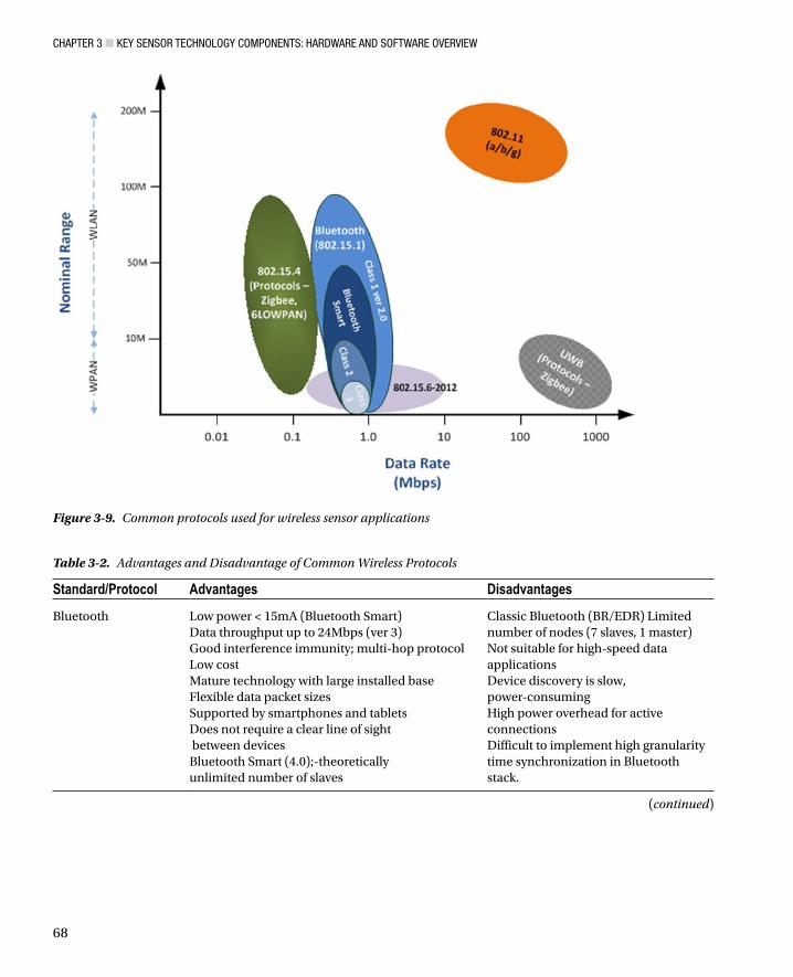
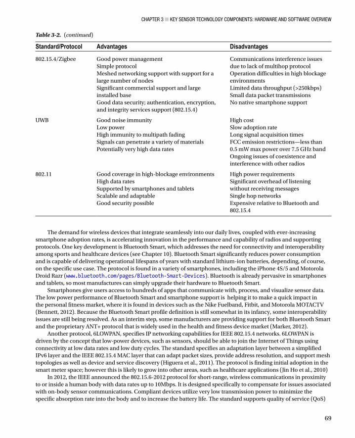
Four key short-range, low-power, wireless communication standards predominate in the sensor application domain. These are: Bluetooth (IEEE 802.15.1) (Eliasson et al., 2008), UWB (IEEE 802.15.3), ZigBee (IEEE 802.15.4), and Wi-Fi (IEEE 802.11). Each of these standards has different data throughputs and ranges (Lee et al., 2007), as shown in Figure 3-9. Bluetooth has been heavily adopted for body-worn applications; Zigbee or 802.15.4 is used for indoor and outdoor multinode network applications; and UWB supports a variety of applications, ranging from implantable sensors (Yuan et al., 2011) to high-precision geolocation determination (Win et al., 2009). Wi-Fi is usually applied in ambient applications where longer ranges, higher data rates, and immunity to signal attenuation in high blockage environments are required. The advantages and disadvantages of each protocol as outlined in Table 3-2 should be considered when selecting the communications method for an application.
Chapter 3 ■ Key SenSor teChnology ComponentS: hardware and Software overview
68
Table 3-2. Advantages and Disadvantage of Common Wireless Protocols
Standard/Protocol Advantages Disadvantages
Bluetooth Low power < 15mA (Bluetooth Smart)Data throughput up to 24Mbps (ver 3)Good interference immunity; multi-hop protocolLow costMature technology with large installed baseFlexible data packet sizesSupported by smartphones and tabletsDoes not require a clear line of sight between devicesBluetooth Smart (4.0);-theoretically unlimited number of slaves
Classic Bluetooth (BR/EDR) Limited number of nodes (7 slaves, 1 master)Not suitable for high-speed data applicationsDevice discovery is slow, power-consumingHigh power overhead for active connectionsDifficult to implement high granularity time synchronization in Bluetooth stack.
Figure 3-9. Common protocols used for wireless sensor applications
(continued)
Chapter 3 ■ Key SenSor teChnology ComponentS: hardware and Software overview
69
The demand for wireless devices that integrate seamlessly into our daily lives, coupled with ever-increasing smartphone adoption rates, is accelerating innovation in the performance and capability of radios and supporting protocols. One key development is Bluetooth Smart, which addresses the need for connectivity and interoperability among sports and healthcare devices (see Chapter 10). Bluetooth Smart significantly reduces power consumption and is capable of delivering operational lifespans of years with standard lithium-ion batteries, depending, of course, on the specific use case. The protocol is found in a variety of smartphones, including the iPhone 4S/5 and Motorola Droid Razr (www.bluetooth.com/pages/Bluetooth-Smart-Devices). Bluetooth is already pervasive in smartphones and tablets, so most manufactures can simply upgrade their hardware to Bluetooth Smart.
Smartphones give users access to hundreds of apps that communicate with, process, and visualize sensor data. The low power performance of Bluetooth Smart and smartphone support is helping it to make a quick impact in the personal fitness market, where it is found in devices such as the Nike Fuelband, Fitbit, and Motorola MOTACTV (Bennett, 2012). Because the Bluetooth Smart profile definition is still somewhat in its infancy, some interoperability issues are still being resolved. As an interim step, some manufacturers are providing support for both Bluetooth Smart and the proprietary ANT+ protocol that is widely used in the health and fitness device market (Marker, 2012).
Another protocol, 6LOWPAN, specifies IP networking capabilities for IEEE 802.15.4 networks. 6LOWPAN is driven by the concept that low-power devices, such as sensors, should be able to join the Internet of Things using connectivity at low data rates and low duty cycles. The standard specifies an adaptation layer between a simplified IPv6 layer and the IEEE 802.15.4 MAC layer that can adapt packet sizes, provide address resolution, and support mesh topologies as well as device and service discovery (Higuera et al., 2011). The protocol is finding initial adoption in the smart meter space; however this is likely to grow into other areas, such as healthcare applications (Jin Ho et al., 2010)
In 2012, the IEEE announced the 802.15.6-2012 protocol for short-range, wireless communications in proximity to or inside a human body with data rates up to 10Mbps. It is designed specifically to compensate for issues associated with on-body sensor communications. Compliant devices utilize very low transmission power to minimize the specific absorption rate into the body and to increase the battery life. The standard supports quality of service (QoS)
Standard/Protocol Advantages Disadvantages
802.15.4/Zigbee Good power managementSimple protocolMeshed networking support with support for a large number of nodesSignificant commercial support and large installed baseGood data security; authentication, encryption, and integrity services support (802.15.4)
Communications interference issues due to lack of multihop protocolOperation difficulties in high blockage environmentsLimited data throughput (>250kbps)Small data packet transmissionsNo native smartphone support
UWB Good noise immunityLow powerHigh immunity to multipath fadingSignals can penetrate a variety of materialsPotentially very high data rates
High costSlow adoption rateLong signal acquisition timesFCC emission restrictions—less than 0.5 mW max power over 7.5 GHz bandOngoing issues of coexistence and interference with other radios
802.11 Good coverage in high-blockage environmentsHigh data ratesSupported by smartphones and tabletsScalable and adaptableGood security possible
High power requirementsSignificant overhead of listening without receiving messagesSingle hop networksExpensive relative to Bluetooth and 802.15.4
Table 3-2. (continued)

Chapter 3 ■ Key SenSor teChnology ComponentS: hardware and Software overview
70
and strong security, essential given the nature of its intended applications, which include EEG, EKG/ECG, and monitoring vital signs such as temperature, heart rate, oxygen, and blood pressure. Beyond healthcare, 802.15.6-2012 may find application in areas such as body-worn game controllers (WPAN-Working-Group, 2012) (Wang et al., 2012).
Another recent wireless standard is ISO/IEC 1453-3-10, which is based on a protocol developed by EnOcean and is optimized for energy harvesting. Sensors based on this standard are mainly focused on monitoring and industrial automation applications (EnOcean, 2012).
Proprietary Wireless Protocols A number of propriety wireless protocols can be found in commercial sensors. These protocols can operate in either the industrial, scientific, and medical (ISM) band or on propriety radio frequencies. They are normally focused on optimizations for specific applications, such as ultra-low power to deliver battery lifespans of years (Smith, 2012). Because of the specific application focus, these protocols are lighter weight, have less overhead, and generally provide more predictable performance than standards-based protocols. It is up to application developers to decide whether the advantages of specific optimizations afforded by proprietary solutions outweigh the flexibility and openness of standard protocols.
ANT is a proprietary ISM band wireless sensor network protocol designed and marketed by Dynastream Innovations Inc. (a subsidiary of the GPS manufacturer, Garmin). It has been incorporated into a number of low-power RF transceivers from companies such as Nordic Semiconductor and Texas Instruments (TI). ANT focuses primarily on applications with low frequency parameters and has been widely adopted in the health and fitness domain, with over 300 companies offering products based on this protocol. A key limitation of ANT, however, is the lack of smartphone and tablet support; only the HTC Rhyme and Sony Ericsson Xperia phones offer native ANT support.
Sensium, a system on a chip (SoC) developed by Toumaz Technology Ltd, is used in ultra-low power body-worn applications to continuously monitor vital signs, such as temperature, heart rate, pulse, and respiration at date rates up to 50Kbps. Data is streamed over 868/915MHz radio to a base station for storage. Sensium is based on a mixed signaling approach, where digital elements are used to dynamically control analog processing blocks to achieve low power utilization. The sensor is designed to operate for a year on a single 30mAhr battery (Bindra, 2008) (Toumaz, 2013).
The BodyLAN wireless protocol from FitLinxx is another proprietary solution for body-worn applications, reportedly used in over 4 million activity, wellness, fitness, and medical devices (FitLinxx, 2013). SimpliciTI from TI is a low-power protocol that runs on the RF SoC series or MSP430 MCU, both from TI, for simple ambient applications such as occupancy detection, carbon monoxide sensing, smoke detection, and automatic meter reading (Texas Instruments, 2008). Other solutions include MicrelNet from Micrel (Micrel, 2012) and MiWi/MiWi P2P from Microchip Technology, based on the IEEE 802.15.4 for wireless personal area network (WPAN) implementations (Microchip, 2013).
Power Management and Energy HarvestingMany sensors, particularly wireless sensors, rely on batteries as their power source. Energy becomes a significant constraint in applications where the sensor must operate unattended for long durations. Replacing batteries can be a costly overhead, particularly if deployments are geographically dispersed or if there are logistical issues in accessing the sensors—for example, sensors attached to a street light post. As a result, much effort has been invested in the efficient use of battery energy and in the harvesting of energy from the environment. Power management has focused primarily in the wireless sensor domain; however, it is relevant to any sensor with a battery power source. Power management employs a variety of mechanisms to minimize power consumption, including turning off sensor subsystems, such as radio communications; using more power-efficient protocols; and optimizing message structures. The choice of power-management technique is determined by the application’s environmental characteristics and performance requirements, such as reliability, and protocol needs. We will briefly look at the most important elements of power management and energy harvesting that application developers should be cognizant of.
Chapter 3 ■ Key SenSor teChnology ComponentS: hardware and Software overview
71
Power ManagementAlthough an in-depth analysis of power control algorithms and protocols is beyond our current scope, we will briefly look at the key elements of power management. Communications—particularly the physical, data link, and network protocol layers of wireless communications—consume a significant proportion of the overall sensor energy (Lin et al., 2009). One area of focus has been the development of energy-efficient MAC protocols. Overhead—associated with managing network functions, such as collision management, control packets, and listening to send/resend—is a constant power drain. Contention-based MAC protocols, such as CSMA/CA (carrier sense multiple access/collision avoidance), require nodes to contend for access to the transmission medium and are therefore are less power-efficient due to that overhead. Scheduled-based protocols, such as TDMA, offer more predictable network behavior as each node has a transmission slot to transmit in. This results in lower overhead, lower power requirements, and the ability to switch sensors off between communications cycles. This off-on cycle is not without overhead, however, and needs to be balanced against the potential energy savings (Chin et al., 2012).
A variety of energy-efficient MAC protocols based on TDMA have been reported in the literature, such as using the frequency of the heartbeat to perform TDMA synchronization, avoiding the energy consumption associated with transmitting time synchronization beacons. In environments where the radio link quality is marginal or there is intermittent inference, the reliability of the packet transmission is related to packet size. Reducing the packet size can improve transmission reliability in fading environments. However, if the packet size is too small, excessive transmissions are required, resulting in energy inefficiency.
Other approaches to power management include policy-based methods such as timeouts, which are implemented in firmware. The sensor is automatically switched into low-power sleep mode if it is idle for a defined period of time. It “wakes up” from its sleep state to make measurements or send and receive transmissions before returning to its sleep state. This approach can be augmented with the addition of a tilt or vibration sensor for detecting movement or motion, which can be used to wake other subsystems that are maintained in a sleep state until required. Alternatively, acoustic or optical sensors (for example, near-infra red) can also be used as the triggering mechanism. The rendezvous approach, where sensor nodes are synchronized to periodically wake and communicate with each other, is also used in the sensor world. Similarly, asynchronous wakeup can be used to wake sensor nodes individually on a scheduled basis. The waking time for each sensor is designed to overlap sufficiently with neighboring nodes to enable the exchange of messages. Another method is topology control, where the power output of the radio is adjusted based on the known position of each node in the network. This can be used effectively in static networks, where the distance between the nodes does not change (Zheng et al., 2006).
Energy HarvestingThe operational lifespan of many sensors is based the availability of power. A variety of battery types are commonly used in sensors, ranging from standard alkaline to Li-ion/NiMH/Li-polymer. However, batteries have a finite energy capacity, and this limitation has generated significant interest in the use of energy-harvesting or energy-scavenging techniques to increase battery life by either recharging them on an on-going basis or at regular intervals, coupled with effective power management to maximize operational lifetime.
Alternatively, an energy-harvesting mechanism can replace a battery altogether, allowing the sensor to operate perennially. This can be thought of as an energy-neutral operation, as the harvesting node consumes only as much energy as the energy-harvesting source is generating (Kansal et al., 2006). The use of energy harvesting with wireless sensors is challenging, as sensors normally require power in the range of 1 to 100 milliwatts (depending on configuration and sensor types) when fully powered up. Current energy-harvesting technologies generally can’t supply this level of power continuously.
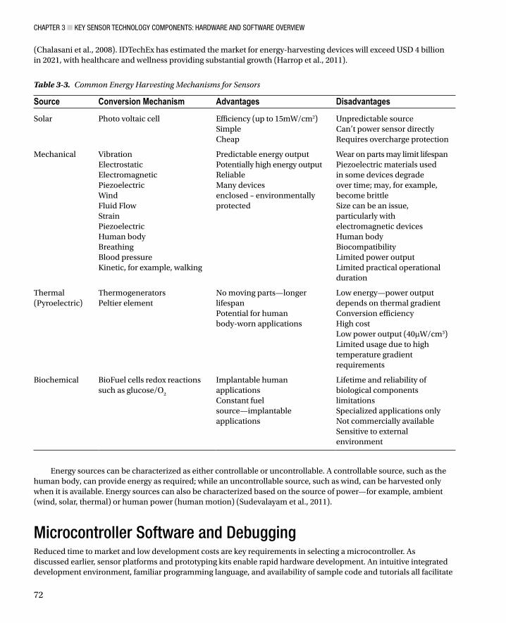
To address this limitation, wireless sensor nodes often adopt an intermittent mode where the sensor remains in a deep sleep or standby mode between measurement cycles. An energy-harvesting mechanism, such as solar, charges a high-capacity energy storage device that can supply the short term high-energy output required during the wake cycle (Boisseau et al., 2012). A variety of methods have been utilized for energy harvesting. A summary of these methods with their respective advantages and disadvantages is presented in Table 3-3 (Gilbert et al., 2008)
Chapter 3 ■ Key SenSor teChnology ComponentS: hardware and Software overview
72
(Chalasani et al., 2008). IDTechEx has estimated the market for energy-harvesting devices will exceed USD 4 billion in 2021, with healthcare and wellness providing substantial growth (Harrop et al., 2011).
Table 3-3. Common Energy Harvesting Mechanisms for Sensors
Source Conversion Mechanism Advantages Disadvantages
Solar Photo voltaic cell Efficiency (up to 15mW/cm2)SimpleCheap
Unpredictable sourceCan’t power sensor directlyRequires overcharge protection
Mechanical VibrationElectrostaticElectromagneticPiezoelectricWindFluid FlowStrainPiezoelectricHuman bodyBreathingBlood pressureKinetic, for example, walking
Predictable energy outputPotentially high energy outputReliableMany devices enclosed – environmentally protected
Wear on parts may limit lifespanPiezoelectric materials used in some devices degrade over time; may, for example, become brittleSize can be an issue, particularly with electromagnetic devicesHuman bodyBiocompatibilityLimited power outputLimited practical operational duration
Thermal(Pyroelectric)
ThermogeneratorsPeltier element
No moving parts—longer lifespanPotential for human body-worn applications
Low energy—power output depends on thermal gradientConversion efficiencyHigh costLow power output (40mW/cm3)Limited usage due to high temperature gradient requirements
Biochemical BioFuel cells redox reactions such as glucose/O
2
Implantable human applicationsConstant fuel source—implantable applications
Lifetime and reliability of biological components limitationsSpecialized applications onlyNot commercially availableSensitive to external environment
Energy sources can be characterized as either controllable or uncontrollable. A controllable source, such as the human body, can provide energy as required; while an uncontrollable source, such as wind, can be harvested only when it is available. Energy sources can also be characterized based on the source of power—for example, ambient (wind, solar, thermal) or human power (human motion) (Sudevalayam et al., 2011).
Microcontroller Software and Debugging Reduced time to market and low development costs are key requirements in selecting a microcontroller. As discussed earlier, sensor platforms and prototyping kits enable rapid hardware development. An intuitive integrated development environment, familiar programming language, and availability of sample code and tutorials all facilitate
Chapter 3 ■ Key SenSor teChnology ComponentS: hardware and Software overview
73
rapid software development. Reductions in development cost can be achieved using free IDEs, such as the Arduino IDE, the MPLAB IDE (for PIC microcontrollers) and Eclipse (plus the Android SDK for Android devices). For complex applications, however, commercial IDEs that include optimized machine code generators and debug tools, such as Keil mVision (www.keil.com/uvision/), may provide time savings and prove less costly overall.
Programming a microcontroller requires two computers: a target computer (the microcontroller to be programmed) and a host computer (the PC used to develop the microcontroller software and send it to the target). Several types of software are required at various stages of the development process: editors, to create and edit code; compilers, to convert code to a machine-readable format; device-programming software, to download the machine code to the target; and a bootloader, to invoke the machine code on the target device. Of course, the compiled code, which is used to control the microcontroller, is also software.
This section covers the different types of software and their use during the software development lifecycle. It also describes the software and hardware debugging methods employed to test embedded applications.
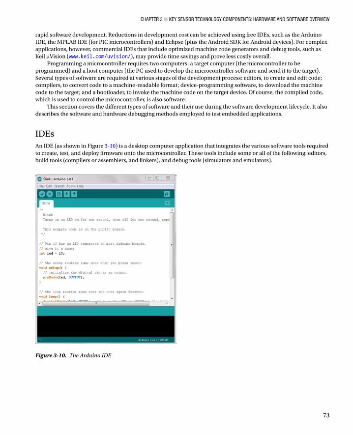
IDEsAn IDE (as shown in Figure 3-10) is a desktop computer application that integrates the various software tools required to create, test, and deploy firmware onto the microcontroller. These tools include some or all of the following: editors, build tools (compilers or assemblers, and linkers), and debug tools (simulators and emulators).
Figure 3-10. The Arduino IDE
Chapter 3 ■ Key SenSor teChnology ComponentS: hardware and Software overview
74
A source code editor is a text editor designed specifically for editing source code. Although •any text editor can be used to write and edit source code, source code editors are easier for programmers to use because they include features such as syntax highlighting, autocomplete, and bracket matching.
A compiler is a computer program that evaluates and optimizes high-level source code, such •as C, against the programming language’s syntax. If the source code correctly follows the rules of the syntax, the compiler translates the source code into machine code and places it in an object file. The compilers in microcontroller IDEs are more accurately described as “cross compilers,” because the code is compiled on one type of computer and deployed on another.
An assembler translates low-level assembly code into machine code.•
A linker links the object file from the compiler to object files from other sources, including •other compiled files, real-time operating system (RTOS) modules, and system libraries. The result is an executable file, called a hex file. In microcontroller IDEs, the linker is often part of the compiler rather than a standalone piece of software.
Most modern MCUs support in-system programming (ISP), which allows the user to program •the device in the circuit by connecting an adapter between the circuit board and the PC. The device-programming software is usually integrated into the IDE, but it can also be used as standalone software.
The bootloader is a piece of software that resides in the ROM of the MCU and executes when it •is started or reset. It is a key component in supporting the ISP features of an MCU.
The most common IDEs are the Arduino IDE, MPLAB for the PIC microcontroller (www.microchip.com/pic) and Keil mVision. Each of these IDEs offers a code editor, an integrated compiler and linker, and a device programmer. The Keil IDE also features debug and emulation tools and can be used to program 8051-based and ARM devices from various manufacturers.
Development LanguagesThe CPU can only understand and execute machine code, which consists of very simple instructions (opcodes) and data (operands) that must be processed. Machine code instructions are difficult to read and vary greatly among individual processors. Almost all MCU programs are written in assembly language or C, which are closer to natural language than obscure machine code. However, they still support key system functionality, such as access to registers. Java can also be used to program embedded devices, but this is less common.
Assembly is a low-level language, in which each instruction corresponds to a single machine •code instruction. Opcodes are described using an English word, such as jump, rather than a number. As with machine code, it is very closely coupled to an individual processor and produces very efficient code. However, it is slow and difficult to program.
C (or variants of C including the Arduino programming language and nesC) is the most •common programming language for microcontrollers. It provides all the features of a higher-level language while allowing the programmer to insert assembly statements if granular control is required. Modern C compilers generate efficient machine code for the MCU, without the programmer having to understand machine code. In many cases, this layer of abstraction from the MCU ensures that code can be recompiled and used for similar MCUs with minimal effort.

Chapter 3 ■ Key SenSor teChnology ComponentS: hardware and Software overview
75
nesC (network embedded systems C) is a C-variant language used to create real-time TinyOS •applications. It consists of components that are wired together via their interfaces to create an application. Shimmer and TelosB motes are programmed using this language.
Java is an interpreted object-orientated language and therefore requires a more powerful •processor than 8-bit and 16-bit MCUs. However, it is becoming more widely used: Java is the main programming language for Android applications, and a Java runtime (Java ME Embedded) has been developed especially for ARM-based MCUs.
Testing CodeDebugging embedded systems requires different methods than debugging PC-based applications, because of the different peripherals available to each computer type. Embedded systems lack a mouse, keyboard, and monitor; however, they have easy access to LEDs, LCDs, and breakout pins, which can be used to provide debug information to the user. In-circuit emulation, background debug mode (BDM), and simulators are the most common methods for performing step-by-step debugging of the source code.
• Line-by-line debugging: ICE and BDM were described earlier: ICE physically replaces the target processor with a processor that emulates the target’s functionality, while BDM uses the target processor to step through and test the code. Simulators model the behavior of the target microcontroller in software (and some simulators allow the programmer to model basic external events). However, simulators are not fast enough to replicate a microcontroller’s real-time behavior, nor can they accurately model the behavior of external components. Simulators are most useful for evaluation of software, which does not use external peripherals, or for initial evaluation of software before debugging the hardware.
• Verbose error messages: The RS232 interface can be used to print error and debug messages from the microcontroller to the serial port. Data from the serial port can be entered and viewed on a terminal emulator on the PC. Verbose messages can also be printed to the microcontroller’s LCD display, if one exists.
• Pin debugging: Setting or clearing a port pin is a quick and crude method for indicating that a certain point in code has been activated, and controlling the timing between events. Similarly, an LED can be set and cleared to provide a visual indication of the software status.
SummaryIn this chapter we have described features and differences among smart sensors, sensor systems, and sensor platforms. We’ve also outlined the hardware and software components required to interface with sensors, build sensor systems, and integrate sensors into high-level systems or to display data to end users. Microcontrollers, the building blocks of low-cost sensor-based systems, have been described in detail, as were the internal and external communication protocols used to transfer data. Finally, we reviewed the software languages and development environments required to control a smart sensor and discussed various debug methods that are commonly used.

Chapter 3 ■ Key SenSor teChnology ComponentS: hardware and Software overview
76
ReferencesHuijsing, Johan H, “Smart Sensor Systems: Why? Where? How?,” in Smart Sensor Systems, Meijer, Gerard C. M., Ed.,
New York, Wiley, 2008.Mathas, Carolyn. “Smart Sensors - Not Only Intelligent, but Adaptable”, Last Update: 2011, http://www.digikey.com/
us/en/techzone/sensors/resources/articles/intelligent-adaptable-smart-sensors.htmlPRWeb. “Global Smart Sensors Market to Reach US$6.7 Billion by 2017, According to New Report by Global Industry
Analysts, Inc.”, Last Update: 2012, http://www.prweb.com/releases/smart_sensors/flow_pressure_sensors/prweb9251955.htm
Córcoles, Emma P. and Martyn G. Boutelle, “Implantable Biosensors,” in Biosensors and Invasive Monitoring in Clinical Applications, Springer International Publishing, 2013, pp. 21–41.
Meijer, Gerard, “Interface Electronics and Measurement Techniques for Smart Sensor Systems,” in Smart Sensor Systems, Meijer, Gerard, Ed., Chichester, John Wiley & Sons, 2008, pp. 23–24.
Hunter, Gary W., Joseph R. Stetter, Peter J. Hesketh, and Chung-Chiun Liu, “Smart Sensor Systems”, Interface, vol. 19 (4), 29–34, 2010.
Pecht, Michael G., Prognostics and Health Management of Electronics. Hoboken, New Jersey: Wiley, 2008.Burns, Adrian, et al., “SHIMMER™ – A Wireless Sensor Platform for Noninvasive Biomedical Research,” IEEE Sensors,
vol. 10 (9), pp. 1527–1534, 2010.Hector, Jonathan. “How to choose an in-circuit emulator”, Last Update: 2002, http://eetimes.com/electronics-news/
4134723/How-to-choose-an-in-circuit-emulatorLee, Kang, “A Smart Transducer Interface Standard for Sensors and Actuators,” in The Industrial Information
Technology Handbook, Zurawski, R., Ed., Boca Raton, FL, CRC Press, 2005, pp. 1–16.Rouse, Margaret. “Serial Peripheral Interface (SPI)”, Last Update: March 2011, http://whatis.techtarget.com/
definition/serial-peripheral-interface-SPIEE Hearld, “SPI Bus interface”, http://www.eeherald.com/section/design-guide/esmod12.html, 2006.Bates, Martin, “Sensor Interfacing,” in Interfacing PIC Controllers, Oxford, Newnes, 2006, pp. 236–238.Kester, Walt, “Sensor Signal Conditioning,” in Sensor Technology Handbook, Wilson, Jon S., Ed., Burlington, MA,
Elsevier, 2005, pp. 87–89.Eliasson, Jens, Per Lindgren, and Jerker Delsing, “A Bluetooth-based Sensor Node for Low-Power Ad Hoc Networks,”
Journal of Computers, vol. 3 (5), pp. 1–10, 2008.Lee, Jin-Shyan, Yu-Wei Su, and Chung-Chou Shen, “A Comparative Study of Wireless Protocols: Bluetooth, UWB,
ZigBee, and Wi-Fi,” presented at the 33rd Annual Conference of the IEEE Industrial Electronics Society (IECON), Taipei, Taiwan, 2007.
Yuan, Gao, et al., “Low-Power Ultrawideband Wireless Telemetry Transceiver for Medical Sensor Applications,” Biomedical Engineering, IEEE Transactions on, vol. 58 (3), pp. 768–772, 2011.
Win, Moe Z., Davide Dardari, Andreas F. Molisch, and Jinyun Zhange, “History and Applications of UWB,” Proceedings of the IEEE, vol. 97 (2), pp. 198–204, 2009.
Bennett, Brian. “The Power of Bluetooth 4.0: It’ll change your life”, Last Update: March 2nd 2012, http://news.cnet.com/8301-1035_3-57389687-94/the-power-of-bluetooth-4.0-itll-change-your-life/
Marker, Ray. “The current state of Bluetooth Smart/Low Energy in Sports Technology (and why it matters to you)”, Last Update: July 31st 2012, http://www.dcrainmaker.com/2012/07/the-current-state-of-bluetooth-smartlow.html
Higuera, Jorge E. and Jose Polo, “IEEE 1451 Standard in 6LoWPAN Sensor Networks Using a Compact Physical-Layer Transducer Electronic Datasheet,” Instrumentation and Measurement, IEEE Transactions on, vol. 60 (8), pp. 2751–2758, 2011.
Jin Ho, Kim, Haw Rim, and Hong Choong Seon, “Development of a Framework to Support Network-based Mobility of 6LoWPAN Sensor Device for Mobile Healthcare System,” in Consumer Electronics (ICCE), 2010 Digest of Technical Papers International Conference on, 2010, pp. 359–360.
Wireless Personal Area Network WPAN Working Group, “802.15.6-2012 - IEEE Standard for Local and Metropolitan Area Networks - Part 15.6: Wireless Body Area Networks”, http://standards.ieee.org/findstds/ standard/802.15.6-2012.html, 2012.

Chapter 3 ■ Key SenSor teChnology ComponentS: hardware and Software overview
77
Wang, Jianqing and Qiong Wang, “Introduction to Body Area Communications,” in Body Area Communications: Channel Modeling, Communication Systems, and EMC, Singapore, Malaysia Wiley-IEEE Press, 2012.
EnOcean. “EnOcean Wireless Standard - First ISO/IEC wireless standard optimized for solutions with ultra-low power consumption and energy harvesting”, Last Update: 2012, http://www.enocean.com/en/enocean-wireless-standard/
Smith, Phil. “Comparing Low-Power Wireless Technologies”, Last Update: 2012, http://www.digikey.com/us/en/ techzone/wireless/resources/articles/comparing-low-power-wireless.html
Bindra, Ashok, “Medical Info-communications Signals an Era of Body Area Networking”, Microwaves and RF, vol. 47, 10–14, 2008, http://rfdesign.com/next_generation_wireless/short_range_wireless/0208RFDFeature1.pdf
Toumaz. “SensiumVitals®”, Last Update: 2013, http://www.toumaz.com/toumaz-healthcare#.UoNbQ_nQCSpFitLinxx. “BodyLAN Wireless Protocol”, Last Update: 2013, http://www.fitlinxx.net/bodylan-wireless-protocol.htmTexas Instruments, “SimpliciTI™ - RF Made Easy”, http://www.ti.com/corp/docs/landing/simpliciTI/index.htm?
DCMP=hpa_rf_general&HQS=NotApplicable+OT+simpliciti, 2008.Micrel. “Introducing the RadioWire® MicrelNet™”, Last Update: 2012, http://qwikradio.com/page.do?page=product-
info/Micrelnet/Micrelnet.shtmlMicrochip. “MiWi™ Protocol”, Last Update: 2013, http://www.microchip.com/pagehandler/en-us/technology/
personalareanetworks/technology/home.htmlLin, Xiao-Hui, Yu-Kwong Kwok, and Hui Wang, “Energy-Efficient Resource Management Techniques in Wireless
Sensor Networks,” in Guide to Wireless Sensor Networks, Misra, Sudip, Subhas Chandra Misr, and Isaac Woungang, Eds., London, Springer-Verlag, 2009, pp. 439–468.
Chin, Craig A., Garth V. Crosby, Tirthankar Ghosh, and Renita Murimi, “Advances and Challenges of Wireless Body Area Networks for Healthcare Applications,” in Computing, Networking and Communications (ICNC), 2012 International Conference on, 2012, pp. 99–103.
Zheng, Rong, Jennifer C. Hou, and Ning Li, “Power Management and Power Control in Wireless Networks,” in Ad Hoc and Sensor Networks, Pang, Yi and Yang Xiao, Eds., New York, Nova Science, 2006, pp. 1–30.
Kansal, Aman, Jason Hsu, Mani Srivastava, and Vijay Raghunathan, “Harvesting Aware Power Management for Sensor Networks,” in 43rd Annual Design Automation Confernce San Francisco, California, 2006, pp. 651–656.
Boisseau, Sebastien and Ghislain Despesse. “Energy Harvesting, Wireless Sensor Networks & Opportunities for Industrial Applications”, Last Update: 27th Febuary, 2012, http://www.eetimes.com/design/smart-energy-design/4237022/Energy-harvesting--wireless-sensor-networks---opportunities-for-industrial-applications?pageNumber=1
Gilbert, James M. and Farooq Balouchi, “Comparison of Energy Harvesting Systems for Wireless Sensor Networks,” International Journal of Automation and Computing, vol. 5 (4), pp. 334–347, 2008.
Chalasani, Sravanthi and James M. Conrad, “A Survey of Energy Harvesting Sources for Embedded Systems,” in IEEE Southeastcon 2008, pp. 442–447.
Harrop, Peter and Raghu Das, “Energy Harvesting and Storage for Electronic Devices 2011–2021”, IDTechEx, Cambridge, UK, 2011.
Sudevalayam, Sujesha and Purusgottam Kulkarni, “Energy Harvesting Sensor Nodes: Survey and Implications,” IEEE Communications Surveys & Tutorials, vol. 13 (3), pp. 443–461, 2011.