kepco power supply - american memory: remaining...
TRANSCRIPT

KEPCO POWER SUPPLY Latest InformatIon on the development and application of VoltageCurrent Regulted Power SupplIes
KEPCO Inc bull 131-38 Sanford Ave Flushing NY 11352 bull Phone (212) IN 1-7000 bull TWX 212-539-6623 bull Cable KEPCOPOWER NEWYORK VOLUME 9 - NUMBER 146-1147 copy KEPCO Inc 1966
THE NEW KG ISOLATED MODULAR POWER SUPPLY by JOSEPH R GATLEY Sr Design Engineer
Model KG 25-02 was designed and developed to fili the need
for a super-regulated isolated modular power supply of Kepco
quality Its voltage and current range of 0 -25 volts at 0-02 ampshy
eres was selected to cover the requirements of most transducer apshy
plications The package is designed for convenient eight-in-a-row
rack mounting (514 high ) to match multiunit installations comshy
mon in transducer system installations
Batteries have long been used as isolated power sources in critishycal applications but the obvious drawbacks of aging drift and reshy
placement nuisance plus the lack of adjustment and means of
remote error sensing have caused a shift to more sophisticated
hardware
In order to achieve the required accuracy with modern bridge
ISOLATION TRANSFORMER FOR STRAIN GAUGE POWER SUPPLY
by ARTHUR ROSIN and FRANKLIN ROSENDUSCH
Kepro Magnetics Division
A power supply for strain gauge operation imposes a number
of unusual requirements on the transformer which powers it A companion article in this issue of the Kepco Power Supply News
The New KG Modular Power Supply develops in detail the
necessity for minimizing AC line leak-through and maximizing
common mode rejection
Translated into transformer terminology the critical parameters
may be summarized as follows
I The effective input-to--output capacitance (C x) is to be less
than 10 pf
2 Capacitance (Cg) between transformer secondary and
ground is to be less than 100 pf and the parallel leakage
resistance (Rg) is to be much greater than 10000 megohms
3 Pickup of stray AC fields by the transFormer secondary or
subsequent circuitry is to be minimized
This article will outline the techniques employed to realize
the desired specifications
Continued on Page 3 - Col 1
measurement systems unusual demands are made on the power
supplies The ideal source for such applications has been described
as a zero-impedance battery suspended in free space While this
ideal will never be realized a close approximation has b~en attained
in the new Kepco Model KG 25-02 Power Source
The isolation capacitance from output to AC input is called C
and is less than 10 picofarad in this new moclcl Capacitance beshy
tween DC output and ground (Cg) is held to less than 200 picoshy
farads with a parallel resistance greater than 10000 megohms
The importance of these parameters will be illustrated in an exshy
ample given further on
Regulation the variation of output versus line and load parashy
meters is also extremely important in transducer applications The
regulation of Model KG 25-02 power supply has been conservashy
tively designed for less than 0 00 I output voltage change versus
line voltage variation of 105-125V AC and less than 0005
output voltage change (or 05 mY whichever is greater) for a
lc1ad change of 0 -200 rna These specs are typically conservative
and allow a wide margin of safety Temperature coefficient anshy
other very important parameter has been given a great deal of attention in this model to reduce its contribution to variation in
output to less than 0005 per C Eight hour stability the reshy
sidual driFt at constant line load and temperature is less than
0005 (or 10 mY whichever is greater)
Continued on Page 2 - Col I
SHOW VAN USED BY NACO ELECTRONICS CORP
The NACO Electronics Corp Kepcos upstate New York State
sales representatives cover a great deal of territory with th eir sales
demonstration van This brings to Kepco customers first hand
demonstrations and visual inspection of Kcpco regulated power
supplies The following tells their story
Continued on Page 5 - Col
ISOLATEO MODULAR POWER SUPPLY Page 1 ISOLATION TRANSFORMATION Page 1 SHOW VAN DEMONSTRATES APPLICATIONS Page 1 NEW POWER SUPPLY ADOITIONS ___ Page 5 GLOSSARY OF POWER SUPPLY TERMS Page 6
vi
THE NEW KG ISOLATED MODULAR POWER SUPPLY s Continued from Page 1 - Col 2 in the input transformer so there are no AC leads whatsoever on
the front panel (There is no AC switch and the pilot lamp is Tight regulation such as this is achieved through the use of new DC operated)
and improved circuitry which maintains extremely close control of ic Of the component parts the most severe requirements are imshyall critical voltages and currents internal to the unit The allshy to
posed on the input transformer supplied by Kepco ~Jagnetics Inc e esilicon circuit includes fOllr temperature-compensated zener dishyThe design considerations for this special transformer are describedodes all with operating currents rigidly pegged to their optimum G in detail elsewhere The isolation capabilities of the Ilodel KGmiddotalues High internal gain and high quality loll noise circuit comshy ar 25-02 arc closely linked to the characteristics of this componentponents reduce the residual output ripple and noise voltage to less y
than 100 microvolts rms ipplications ior isolated or glarded DC power supplies range m
from field civil engineering to tIle laboratories of medical electronshy faA ten-turn locking voltage control mounted on the front panel ics In fact such supplies find lise in any branch of science orprOlides a voltage adjustment resolution to better than 002 (5 engineering where precise measurel1lents free from spurious inshymillivolts) A vcr) sharp current-limit adjust also accessible from su dicattions are reqUiredthe front can be set to limit short-circuit current as close as 20 rna gr
above working load current thus providing a high degree of proshy Resistive bridge transducers especially require a clean freeshy
tection for external circuitry Aoating source of DC voltage so do the free-Aoating amplifiers 10
The current limit is 110t affected by accidental opening of the which boost their minute signals Since the isolation of such an
error sensing leads amplifier is no better than its power supply the need for a well
isolated source is obviousOutput impedance is ery low (6 milliohms at DC) and negli shy
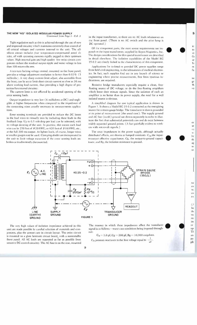
gible at higher frequencies hen compared to the impedance of A simplified diagram for one typical application is shown in
the connecting wires usually necessary in measurements applicashy Figure 1 It shows a ilodel KG 25-02 connected as the energizing
tions source for a strain gauge bridge The transducer is shown grounded
at its point of measurement (the usual case) The supply groundError sensing terminals arc provided to reduce the DC losses and C line (earth) ground are shown separately in order to illusshyin the load wires to virtually zero by including these leads in the trate the fact that substantial potentials can and do exist betweenfeedback loop lip to 05 volt drop per lead can be tolerated with erwidely separated ground points (A fact painfully evident to workshyno voltage derating of the unit In practice this means each load ers with microvolt signals)
se lire can be 250 feet of 20 WG or 620 feet of 16AWG etc middot 8
at the full 200 ma output At lighter loads of course longer wires The stray impedances in the power supply although actually II
or smaller gauges mal be used Clamping diodes are incorporated in distributed effects are shown as lumped constants C x the inputshy
the unit to limit oltage excursion if the error sensing leads arc to-outPlit effective capacitance Cg the output-to-ground capacishy th broken or inadertently disconnected tance and Rg the isolation resistance to ground
e e he
ag
thLINE SUPPLY TRANSDUCER (EARTH) GROUND GROUND vo
FIGURE 1 GROUND rei
itse erThe manner in which these impedances affect the transducerThe very high alues of isolation impedance achieved in this signal is as follows-worst case conditions being imposed throughshy op
out unit are made possible bv careful selection of materials and comshy
T~ponents plus the utmost care in circuit layout The enire circuit -C x = 10 pf C g = 200 pf Rg = 10000 megohms anis mounted on a glass laminate circuit board with a nonmetallic
poftont panel All AC Jeads are separated as far as possible from C x presents reactance to the line voltage equal to 1
phsensitie DC control circuitrl The AC fuse is on the rear mounted we
2
r------------
AC LINE
I I I L
I I L J
I
+e + ()-I---I shy
KG 25 -02
- (J ()-I---- shy
I ~
------amp-----shypound2
se
se
STRAIN GAUGE BRIDGE (350Il )
SU
m Wi
en
a (
cr ln
At 60 Hz this is
I =26 5xI0ohms (628)(60 )( 10-)
For a 120 volt input an AC lea kage current of 120 _ _
2 6 5 x 10 - 452 x 10
amperes will Ao This current re turning through a typical 350
ohm bridge will generale a voltage equal to( 4 52 x 10 x 350)
volts o r 15 8 microvolts ( rms) This voltage o f course will onl y
appear in the tr ansd ucer output as a percentage proportional to
the bridge unbalance eg with a 1 unbalancc the AC ripple or
noise vo ltage attribu ta ble to C x at th e bridge output would be ap shy
proximately 016 microvol t rm s or 045 microvolt peak-to-peak
Cg offe rs a reac tance to the comm on-mode vo ltage of E2 of
( 8) ( O~ ( - 0) = 133 x 10 ohms 6 2 62x10
The pa ralleled res istance Rg o f at leas t 10 0 ohms being nearl y
th ree orde rs of magnitu de grea ter has il neg li gib le effect on the
absolut e magnitude of the impedance T he ripp le and noise introshy
duced in the bridge output through thi s impeda nce by the comshy
mon-mode voltage E2 is of course directly proportional to the
magnitude of E2 but if we ass ume E2 to be 10 volt rms then a
current thro ugh Cg and Rg in para lle l will be
E2 _ 1 0 007- - - = 5 mIcroamperesIZI I 33 x 10
This across a 350 ohm bridge will ge nera te
7 5 x 10-8 x 35 x 10 = 262 microvolts
which will aga in at a 1 unbalance result in 026 microvolt s
rms or 0 7 4 microvolts peak-topeak at the output
The foregoing disc ussion points up th e fact th at high impedan ce
to ground is of a t leas t equal impo rtance with ou tp ut-to-Iine isoshy
lation T oo little em phasis is ofte n placed on th is and some manu shy
facture rs neg lec t to specify this parameter
The necessity for the tightest possible regula tion and freedom
from drift in the supply voltage o f low-leve l transducers is too ob shy
vious to be labo r The Model KG 25 -02 h as been designed and
deve loped with all of th ese requirements cle arly in mind and is
representatie of th e present state of Ih e ar t
ISOLATION TRANSFORMER
FOR STRAIN GAUGE POWER SUPPLIES Con tinued fro m Page 1 - Col I
To ga in some perspective into th e nature of the problem the
characteristics of an ordinary tr ansformer such as the one used
in a Kepco Model ABC Power Supply may be used as a reference point The effec tive input-to-output capacitance (C ) of such a
transfo rmer is of the order of 600 pf The seeondary- to-ground
capacitance (Cg) approxim ates 100 pf and the insulation resisshy
tance ma y be as high as 400000 mego hms However the insula shy
ti on resistance of most orga nic mate ri als becomcs h alved for eve ry
6degC increase in tem perature If such material is used in a tran sshy
fonner the initi a l 400 000 megohm insula tion resistan ce may
decrease to as little as 100 megohm s at interna l temperatures of
90degC ( typica l for a 50degC ambient ra ting)
A conventional tra nsformer co mpri ses a coil consisting of conshycen tric primary and secondary windings The mutual capacitance
(C x) between these wind ings can be appreCiated by reference to Figure I
3
LENGTH - L
SEC
PRI
INTERWINDING INSULATiON
(CIRC UM FERENCE =Ll
THICKNESS-T DIELECTRIC CONSTANTK
T~ I 2Q~~~~OOOOOOOooooooooqgggg
~~SlggggggggggQggg
1_ WIDTH OF J r WtNDING=WI
CAPACITANCE =K- WHERE A=WL
FIGURE 1
Th e a rea occupied by the last laye r of the primary winding and
th e fir st laye r of th e second ary form th e cC] ui valc nt of a two-plate
capacitor separated by th e intern-i nding insulation Threc meth ods
offer red uction of the intcrwi nd in g ca pacitance
a ) increase T
b ) decrease K or
c) dec rcase A
Jncreas in g T is practical fur a red uction o f about one order
of magnitude Beyond this point the tr ansformer becomes imprac shy
ticably large Also thc leakage induc tance increases to a poi nt
where the electrica l perform ance is affected
K the die lec tric co nstant of the impregnated paper be twee n
the windings has value of 25 to 30 By making thc primary and
seco nd ary coils se lf-s upportin g the dielectri c become s principally
air and K app roaches 10 This makes poss ible a reduction of
25 to 30 times
1 red uction in the value o f A is not practicable Since th e
volume of the coi l windings is fix ed by the number of turns and
required wire sizes any reduc tion of W will necess itatc a n
inc rease in L and vice ve rsa Therefore no app reciable ad shy
vantage ca n be gai ned in thi s area
The next logica l step is 10 interpose a grounded electrostati c
sh ield be tween the primary and secondary windin gs This effec shy
tively increases the capacity between primary and ground and
be tween secondary and g round but is effec tive in greatl y reduc shy
ing the ca pac itance between primary and secondary In the case of th e Kepco ABC design power tran sformer refe renced above
the mutu al capaci tance was reduced from 600 pf to 10 pf but the secondary-to-ground capacitance increased from 100 pf to
400 pf
It is a l
sign is n
2 is a seT
has been Supply
r I I
I
I I I I L
The S2
I The
nan
are tWCt
2 The
tain miz
tanlt
3 The
ing
furl
sece
4 In
90deg as t
latic Sine
con
at a
con ~
5 ThE
mag
duc
6 The exc
er v
CONSTANT-K
+L
~ary winding and
ent of a two-plate
gtn oThree methods
f about one order
r becomes impracshy
reases to point
cd pa per between
g the primary and comes principally
)Ie a reduction of
tieable Since the
nber of turns and
ill necessitate an
o appreciable adshy
nded electrostatic
dings This effeeshy
ancl ground and in greatly reduc-
Idary In the case
referenced above pf to 10 pf but from 100 ppound to
It is apparent that a radical departure from conventional deshysign is necessary to achieve the desired characteristics Figure
2 is a semi-schematic representation of such an assembly which
has been adopted in the new Kepco IVlodel KG Transducer Power
Supply
INPUT
r --------shy - - I I I I FUSE
I I
I I I
I I I I I I PRIMARY I L - ff r 1 E
J
r-SECONDARY
t-r I Ishy
-
OUTPUT FIGURE 2
The salient features of this special transformer are as follows
I The primary and secondary coils are wound in two separate
narrow pies minimizing the areas over the core and the
areas facing each other This minimizes the capacitance beshy
tween windings as well as the capacitance to core
2 The primary winding including thc fuse is completely conshy
tained in its own elcctrosttic shield This not only minimiddot miz~s mutual capacitance but virtually eliminates capacishy
tance bctween the fu se its wiring and the output
3 The secondary coil is liberally spaced from the primry windshy
ing as well as the core and adjacent surfaces This not only
further attenuates the mutual capacitance but reduces the
secomlary-to-ground capacitance
4 In order to provide the necessary insulation resistance at
90degC (interior temperatures) nonorganic TeAon is used
as the insulating mellium This material has superior insu shy
lation resistance which it retains at elevatecl temperatures
Since its dielectric eonstnt is rather high (~2 5 ) a shell
construction is employed which supports the secondary coil
at a minimum number of points This leaves air (cIielectric
constant =10 ) to fill mos t of the space
5 The entire assembly is surrounded by a case which provides magnetic s well as electrostatic shielcling effcctively reshy
ducing pickup of stray fielcls in the secondary coil
6 The design of the transformer case and its terminals provide exceptionally short (pin) wiring from the various transform shy
er windings to a printed circuit (PC ) board Short leads of
4
approximately I are used to the AC connector giving comshyplete separation of primary and secondary wiring In addishy
tion the location of the transformer on the power supplys
main circuit board serves to enhance the shielding and isoshy
lation of the supply output
Typical performance characteristics of the final production transformers are as follows
Effective input-to-output capacitance (C x) 003-008 pf
Effective secondary-to-g round capacitance (Cg) 20-35 pf
Secondary-to-ground resistance (Rg) 200 K - 250K meg shy
ohms ( at 90degC)
When installed in the power supply with its own unavoidable
capacitances and leakage paths the required specifications are
met with a comfortable margin of safety
At Kepco each magnetic component requirem ent is treated
as an integral part of the circuit design problem with the Circuit
Design and Magnetic Design groups working closely together
Many unique solutions result from this ability to shape circuit pershy
formance by tailoring the electrical and mechanical characteristics
of the magnetic components The Kepco KG 25-02 Strin Gauge
Power Supply is an outstanding example of the aclvantagcs to be gained from this integrated design approach
COMPLEMENTARY PROGRAMMING The use of PNP pnss elements in the Kepco PAX module group
with NPN transistors used ~s the pass in PBX modules ( their sister group ) opens an area of interconnection hitherto not feasshyible Operationally PNP elements require a negativ~ common with a positive output while NPN elements result in a positive common terminal and negat ive output
co
PNP
OPERAT IONAL CONF IGURAT tON
NPN
The fact that the polarity of E(l from one kind of module matches the requirement for EI ( input ) to its complement pershymits the use of cascade circuits in specinl application
NON INVERTING AMPLIFIER PAIR
NEW 52 PAGE 1966 KEPCO CATALOG
Detailed specifications of more than 320 standard Kepco Regulated Power Supplies together with much useful power supply inshyformation are contained in Ctalog Bmiddot663 Write for your copy to Kepco Inc Publica shytions Dept 131-38 Sanford Avenue Flushing NY 11352
SHOW VAN USED BY NACO NEW KS DESIGN GROUP POWER SUPPLIES Ton Continued from Page 1 - Col 2 p is
Kepcos representative in Upstate New York NACO Electronshy
ics finishe d a very successful 2 month mobile demon stration van imshy
tour of the upst He area in December The Mobile Demonstrator Inc e
visiteu such facilities as lBiJ GE Sylvania Bell Aerosystcmsibeu General Dynamics Xerox Westinghouse Griffiss AFB Univac KG MODEL KS 120-tM
and many colleges and universities located in the Upstate New lent The range of output voltage available in the KS Design GroupYork area On board were many representative power supplies ange manufactured by Kepco Jnc as lIell as products of other manushy of Kepco voltage current regulated power supplies has been dou shy
bled by the recent availability of the KS 120-IM KS 120-25Mron - facturers they represent KS 120-5M and KS 120- IOM models These suppbes withe or By using the remote programming capability of the Kepco power
s in shy 0005 line regulation and 00 I load regulation combined supplics one d emonstration cxplaincd the versatility of this proshy
with other important features of the KS series such as automatic gramming capability by electronically varying the frequency of a
voltage current crossover VIX signal mode indicators ( which free- Wavetek function gcnerator as a function of thi s programme d
visually indicate whether the power supply is regulating in voltage fiers Ioltage change
or current mode ) and 10 turn controls for both current and voltshyh an
age make these new KS supplies an important addition to this well outstanding design group engineered and manufactured by Kepco
MODEL MODEL MP 1-3000
n in A8C 40-05M
zing
WAVETEK 105
VOLTAGE CONTROL
GENERATOR NEW PWR ded
und POWER Jlus-
Another demonstra tion illustrated the importance of remote MODULESeen error sensing at the power supply load Without the Rem ote Errorork- BYsensing capability of the Kepco power supplies the voltage
variation at thc load would include the voltage drop in the long KEPCO lally lire leads to the load By the use of the error sensing capability put- e however the load was effectively placed at the output terminals of )acishy the power supply electrically thus in effect eliminating any volt shy
age drop from the powe r supply to the load By switching the error
sense leads in and out of the circuit the load lead drop was obshy
served on a DVM The unique protective current cutoff characteristics of the Kepco
PWR modules make them especially useful in applications re shy
quiring circuit safety These power supplies when heavily overshy
loaded or short circuited automatically reduce output current to a CuBIC MODEL
small fraction of maximum ratings When the overload is removed
however PWR units immediately return to normal operation CK 8-5M DV M
The complete story of this unusual and most useful design group
was carried in Kepco Power Supply News Vol 7 No 146- J 128 Still another demonstra tion showed the ability of a Kepco power Particularly aimcd at the microcircuit field and other Jow voltage
supply to maintain a con stant speed of a motor as the load on the applications two nCI models have iu s t been announced namel) motor was changed J n this demonstration a tachometer output the PWR4-14 and PWR 7- 11 providing 0-4 volts at 0-14 amperes was fed back to the power supply which in turn decreased or inshy and 0-7 volts at 0-11 amperes respec tive l These are highly regushycreased the output voltage from the supply in order to maintain hued power modules rated at 0 005 line and 005 load regushya constant speed of the motor under a varying load
lation They arc full y programmable in voltage Or current modes
Other demonstrations showed the versatility of the VIX~ with external sensing The des ign is based on the Kepco patented
( Automatic Voltage-Current Crossover) of the power supplies Flux-O-Tran line regulating transfonner and fully transistorized
J n demonstrating this fe ature a current limit control was set on bridge regulator also a Kepco patented feature
the Kepco Model CK-8-5i1 I ith a constant load value ( R ) The A further addition to the line is the PWR 36-3 providing 0-36 voltage Iould be increased until the maximum current was volts at 0-3 amperes This unit also possesses all the features ami reached At this point the power supply automatically changed to characteristics of the PWR Design Group as set forth above its constant current mode and became a current regulated pow shy
ucer er supply At the same time the VIX indicator lights slOwed the Complete specifications and desc riptions of these and mOre than
320 standard model Power Supplies a re detailed in the new Kepco
Catalog B-66 3 and available on request Write Kepco I nc Dept ugh- operator he was in the current moue rather than the voltage mode
The output of the VIX Indica tors were then used to close a relay
and actute an alarm light This also clemonstrated the use of a PS 13 LI8 Sanford Avenue Flushing NY 11352
pOler supply to control external devices in man y industrial apshy 1 Ihe n programmed for less than the rated voltage (plusmnS) current rating
plications reduces proportionally
5
TOP KEPCO ENGINEERS SERVE AT IEEE Kepco Display Host to Thousands of Engineers
Kepcos General Manager Mr Max Kupferberg reports that
Kepco will once again play host to visiting electronic engineers at the New York IEEE Meeting
The Kepco show booth itself is a spectacularly attractive design which has had favorable comment wherever shown The arched
backdrop designed by FUNCTIONAL DISPLAYS of Amityville
New York is a handsome yet practical format for the presentation
of Kepco Power Supplies and instruments
Some twenty models will be on displar representing the more
than 320 different power supply models presently available A new
1966 catalog will be distributed and visitors may register for a
complimentary copy of the Kepco Power Supply Handbook Of
greater importance is the fact that this unique display will be conshy
tinuousl) manned by the highest level engineering personnel for
consultation and assistance on application problems
THE KEPCO POWER SUPPLY HANDBOOK Note The respon se to the offer of the Kepco Power Supply Handbook carried in the last issues of Kepco Power Supply News has been so great that IVe are repeating it this month for those who may have missed it Regular readers of the Kepco Power Supply News have become familiar with the many unconventional power supply applications that have been evolved over the years Beyond the classic job of powering other circuits Power Supplies are increasingly finding application as instruments in their own right This field has grown so in the past few )ears that we have undertaken to publish a Handbook covering the more interestshying and useful power supply applicashytions
The Kepco Power Supply Handbook written by Paul Birman Kepcos Application Engineer covers the subject of regulated DC Power Supplies in detail Particular emphasis is placed On the programming concept and its myriad applications to complex systems control problems
Profusely illu strated with innumerable circuit diagrams block diagrams and photographs the Kepco Power Supply Handbook is a valuable addition to any engineering library For a complimenshytary copy contact lOur closest Kepco representative or write on your companys letterhead to Publications Manager Dept K Kepco Inc 131 -3 8 Sanford Avenue Flushing New York 11352
GLOSSARY OF POWER SUPPLY TERMS The new Kepco Power Supply Handbook contains a Glossary of Power Supply Terms addjng 29 new definitions to the already comprehensive list previously published by Kepco Here are some of these new terms and their definitions
FILTERS Filters are RC or LC networks arranged as low pass devices to atshytenuate the varying component that remains when a-c voltage is rectified In power supplies without subsequent active series regushylators the filters determine the amount of ripple that will remain in the d-c output In supplies with active feedback series regulators the regulator mainly controls the ripple with output filtering servshying chiefly for phase-gain control as a lag element
FLUX-O-TRAN shyA registered trademark of Kepco Inc applied to ferro-resonant voltage regulating transformers of a special design which are used in many proprietary designs The Flux-O-Tran with its resonating capacitor provides a squarewave output (for higher rectifier and filter efficiency ) whose magnitude is largely independent of the primary voltage amplitude
AG NETWORKS Resistance -reactive components arranged to control phase-gain rolloff versus frequency Useu to assure the dynamic stability of a power supplys comparison amplifier The main effect of a lag network is a reduction of gain at relatively low frequencies so that the slope of the remaining rolloff can be relatively more gentle
LEAD NETWORKS Resistive-reactive components arranged to control phase-gain rollshyoff versus frequency Used to assure the dynamiC stability of a power supplys comparison amplifier The main effect of a lead network is to introduce a phase lead at higher frequencies near the unity gain frequency
LOOP (LEAKAGE) CURRENT A d-c current flowing in the feedback loop (voltage control) indeshypendent of the control current generated by the reference zener diode source and reference resistor The loop (leakage) current remains when the reference current is made zero It may be comshypensated for or nulled in special applications to achieve a very high impedance (zero current ) at the feedback (voltage control) terminals
LOOP GAIN A measure of the feedback in a closed-loop system being equal to the ratio of the open-loop to the closed-loop gains in db A -G The magnitude of the loop gain determines the error attenuation and therefore the performance of an amplifier used as a voltage regulator (See Open-loop and Closed-loop gain)
MTBF Mean time between (or before) failure
A measure of the reliability giving either the time before first fnilshyure or for repairable equipment the average time between repairs MTBF may be approximated or predicted by summing the reciproshycal failure rates of individual components in an assembly
In place of the overworked term ripple and instead of the reshycently proposed acronym PARD ( Periodic And Random Deviashytion) Kepco proposes a new term CRUD C ontinuous amp Random U nwanted Deviation CRUD has mnemonic advantages over other terms and in addition spedfies that ripples be restricted to unwanted as distinguished from wanted periodic or random waveforms What do Our readers think
6
vi
THE NEW KG ISOLATED MODULAR POWER SUPPLY s Continued from Page 1 - Col 2 in the input transformer so there are no AC leads whatsoever on
the front panel (There is no AC switch and the pilot lamp is Tight regulation such as this is achieved through the use of new DC operated)
and improved circuitry which maintains extremely close control of ic Of the component parts the most severe requirements are imshyall critical voltages and currents internal to the unit The allshy to
posed on the input transformer supplied by Kepco ~Jagnetics Inc e esilicon circuit includes fOllr temperature-compensated zener dishyThe design considerations for this special transformer are describedodes all with operating currents rigidly pegged to their optimum G in detail elsewhere The isolation capabilities of the Ilodel KGmiddotalues High internal gain and high quality loll noise circuit comshy ar 25-02 arc closely linked to the characteristics of this componentponents reduce the residual output ripple and noise voltage to less y
than 100 microvolts rms ipplications ior isolated or glarded DC power supplies range m
from field civil engineering to tIle laboratories of medical electronshy faA ten-turn locking voltage control mounted on the front panel ics In fact such supplies find lise in any branch of science orprOlides a voltage adjustment resolution to better than 002 (5 engineering where precise measurel1lents free from spurious inshymillivolts) A vcr) sharp current-limit adjust also accessible from su dicattions are reqUiredthe front can be set to limit short-circuit current as close as 20 rna gr
above working load current thus providing a high degree of proshy Resistive bridge transducers especially require a clean freeshy
tection for external circuitry Aoating source of DC voltage so do the free-Aoating amplifiers 10
The current limit is 110t affected by accidental opening of the which boost their minute signals Since the isolation of such an
error sensing leads amplifier is no better than its power supply the need for a well
isolated source is obviousOutput impedance is ery low (6 milliohms at DC) and negli shy
gible at higher frequencies hen compared to the impedance of A simplified diagram for one typical application is shown in
the connecting wires usually necessary in measurements applicashy Figure 1 It shows a ilodel KG 25-02 connected as the energizing
tions source for a strain gauge bridge The transducer is shown grounded
at its point of measurement (the usual case) The supply groundError sensing terminals arc provided to reduce the DC losses and C line (earth) ground are shown separately in order to illusshyin the load wires to virtually zero by including these leads in the trate the fact that substantial potentials can and do exist betweenfeedback loop lip to 05 volt drop per lead can be tolerated with erwidely separated ground points (A fact painfully evident to workshyno voltage derating of the unit In practice this means each load ers with microvolt signals)
se lire can be 250 feet of 20 WG or 620 feet of 16AWG etc middot 8
at the full 200 ma output At lighter loads of course longer wires The stray impedances in the power supply although actually II
or smaller gauges mal be used Clamping diodes are incorporated in distributed effects are shown as lumped constants C x the inputshy
the unit to limit oltage excursion if the error sensing leads arc to-outPlit effective capacitance Cg the output-to-ground capacishy th broken or inadertently disconnected tance and Rg the isolation resistance to ground
e e he
ag
thLINE SUPPLY TRANSDUCER (EARTH) GROUND GROUND vo
FIGURE 1 GROUND rei
itse erThe manner in which these impedances affect the transducerThe very high alues of isolation impedance achieved in this signal is as follows-worst case conditions being imposed throughshy op
out unit are made possible bv careful selection of materials and comshy
T~ponents plus the utmost care in circuit layout The enire circuit -C x = 10 pf C g = 200 pf Rg = 10000 megohms anis mounted on a glass laminate circuit board with a nonmetallic
poftont panel All AC Jeads are separated as far as possible from C x presents reactance to the line voltage equal to 1
phsensitie DC control circuitrl The AC fuse is on the rear mounted we
2
r------------
AC LINE
I I I L
I I L J
I
+e + ()-I---I shy
KG 25 -02
- (J ()-I---- shy
I ~
------amp-----shypound2
se
se
STRAIN GAUGE BRIDGE (350Il )
SU
m Wi
en
a (
cr ln
At 60 Hz this is
I =26 5xI0ohms (628)(60 )( 10-)
For a 120 volt input an AC lea kage current of 120 _ _
2 6 5 x 10 - 452 x 10
amperes will Ao This current re turning through a typical 350
ohm bridge will generale a voltage equal to( 4 52 x 10 x 350)
volts o r 15 8 microvolts ( rms) This voltage o f course will onl y
appear in the tr ansd ucer output as a percentage proportional to
the bridge unbalance eg with a 1 unbalancc the AC ripple or
noise vo ltage attribu ta ble to C x at th e bridge output would be ap shy
proximately 016 microvol t rm s or 045 microvolt peak-to-peak
Cg offe rs a reac tance to the comm on-mode vo ltage of E2 of
( 8) ( O~ ( - 0) = 133 x 10 ohms 6 2 62x10
The pa ralleled res istance Rg o f at leas t 10 0 ohms being nearl y
th ree orde rs of magnitu de grea ter has il neg li gib le effect on the
absolut e magnitude of the impedance T he ripp le and noise introshy
duced in the bridge output through thi s impeda nce by the comshy
mon-mode voltage E2 is of course directly proportional to the
magnitude of E2 but if we ass ume E2 to be 10 volt rms then a
current thro ugh Cg and Rg in para lle l will be
E2 _ 1 0 007- - - = 5 mIcroamperesIZI I 33 x 10
This across a 350 ohm bridge will ge nera te
7 5 x 10-8 x 35 x 10 = 262 microvolts
which will aga in at a 1 unbalance result in 026 microvolt s
rms or 0 7 4 microvolts peak-topeak at the output
The foregoing disc ussion points up th e fact th at high impedan ce
to ground is of a t leas t equal impo rtance with ou tp ut-to-Iine isoshy
lation T oo little em phasis is ofte n placed on th is and some manu shy
facture rs neg lec t to specify this parameter
The necessity for the tightest possible regula tion and freedom
from drift in the supply voltage o f low-leve l transducers is too ob shy
vious to be labo r The Model KG 25 -02 h as been designed and
deve loped with all of th ese requirements cle arly in mind and is
representatie of th e present state of Ih e ar t
ISOLATION TRANSFORMER
FOR STRAIN GAUGE POWER SUPPLIES Con tinued fro m Page 1 - Col I
To ga in some perspective into th e nature of the problem the
characteristics of an ordinary tr ansformer such as the one used
in a Kepco Model ABC Power Supply may be used as a reference point The effec tive input-to-output capacitance (C ) of such a
transfo rmer is of the order of 600 pf The seeondary- to-ground
capacitance (Cg) approxim ates 100 pf and the insulation resisshy
tance ma y be as high as 400000 mego hms However the insula shy
ti on resistance of most orga nic mate ri als becomcs h alved for eve ry
6degC increase in tem perature If such material is used in a tran sshy
fonner the initi a l 400 000 megohm insula tion resistan ce may
decrease to as little as 100 megohm s at interna l temperatures of
90degC ( typica l for a 50degC ambient ra ting)
A conventional tra nsformer co mpri ses a coil consisting of conshycen tric primary and secondary windings The mutual capacitance
(C x) between these wind ings can be appreCiated by reference to Figure I
3
LENGTH - L
SEC
PRI
INTERWINDING INSULATiON
(CIRC UM FERENCE =Ll
THICKNESS-T DIELECTRIC CONSTANTK
T~ I 2Q~~~~OOOOOOOooooooooqgggg
~~SlggggggggggQggg
1_ WIDTH OF J r WtNDING=WI
CAPACITANCE =K- WHERE A=WL
FIGURE 1
Th e a rea occupied by the last laye r of the primary winding and
th e fir st laye r of th e second ary form th e cC] ui valc nt of a two-plate
capacitor separated by th e intern-i nding insulation Threc meth ods
offer red uction of the intcrwi nd in g ca pacitance
a ) increase T
b ) decrease K or
c) dec rcase A
Jncreas in g T is practical fur a red uction o f about one order
of magnitude Beyond this point the tr ansformer becomes imprac shy
ticably large Also thc leakage induc tance increases to a poi nt
where the electrica l perform ance is affected
K the die lec tric co nstant of the impregnated paper be twee n
the windings has value of 25 to 30 By making thc primary and
seco nd ary coils se lf-s upportin g the dielectri c become s principally
air and K app roaches 10 This makes poss ible a reduction of
25 to 30 times
1 red uction in the value o f A is not practicable Since th e
volume of the coi l windings is fix ed by the number of turns and
required wire sizes any reduc tion of W will necess itatc a n
inc rease in L and vice ve rsa Therefore no app reciable ad shy
vantage ca n be gai ned in thi s area
The next logica l step is 10 interpose a grounded electrostati c
sh ield be tween the primary and secondary windin gs This effec shy
tively increases the capacity between primary and ground and
be tween secondary and g round but is effec tive in greatl y reduc shy
ing the ca pac itance between primary and secondary In the case of th e Kepco ABC design power tran sformer refe renced above
the mutu al capaci tance was reduced from 600 pf to 10 pf but the secondary-to-ground capacitance increased from 100 pf to
400 pf
It is a l
sign is n
2 is a seT
has been Supply
r I I
I
I I I I L
The S2
I The
nan
are tWCt
2 The
tain miz
tanlt
3 The
ing
furl
sece
4 In
90deg as t
latic Sine
con
at a
con ~
5 ThE
mag
duc
6 The exc
er v
CONSTANT-K
+L
~ary winding and
ent of a two-plate
gtn oThree methods
f about one order
r becomes impracshy
reases to point
cd pa per between
g the primary and comes principally
)Ie a reduction of
tieable Since the
nber of turns and
ill necessitate an
o appreciable adshy
nded electrostatic
dings This effeeshy
ancl ground and in greatly reduc-
Idary In the case
referenced above pf to 10 pf but from 100 ppound to
It is apparent that a radical departure from conventional deshysign is necessary to achieve the desired characteristics Figure
2 is a semi-schematic representation of such an assembly which
has been adopted in the new Kepco IVlodel KG Transducer Power
Supply
INPUT
r --------shy - - I I I I FUSE
I I
I I I
I I I I I I PRIMARY I L - ff r 1 E
J
r-SECONDARY
t-r I Ishy
-
OUTPUT FIGURE 2
The salient features of this special transformer are as follows
I The primary and secondary coils are wound in two separate
narrow pies minimizing the areas over the core and the
areas facing each other This minimizes the capacitance beshy
tween windings as well as the capacitance to core
2 The primary winding including thc fuse is completely conshy
tained in its own elcctrosttic shield This not only minimiddot miz~s mutual capacitance but virtually eliminates capacishy
tance bctween the fu se its wiring and the output
3 The secondary coil is liberally spaced from the primry windshy
ing as well as the core and adjacent surfaces This not only
further attenuates the mutual capacitance but reduces the
secomlary-to-ground capacitance
4 In order to provide the necessary insulation resistance at
90degC (interior temperatures) nonorganic TeAon is used
as the insulating mellium This material has superior insu shy
lation resistance which it retains at elevatecl temperatures
Since its dielectric eonstnt is rather high (~2 5 ) a shell
construction is employed which supports the secondary coil
at a minimum number of points This leaves air (cIielectric
constant =10 ) to fill mos t of the space
5 The entire assembly is surrounded by a case which provides magnetic s well as electrostatic shielcling effcctively reshy
ducing pickup of stray fielcls in the secondary coil
6 The design of the transformer case and its terminals provide exceptionally short (pin) wiring from the various transform shy
er windings to a printed circuit (PC ) board Short leads of
4
approximately I are used to the AC connector giving comshyplete separation of primary and secondary wiring In addishy
tion the location of the transformer on the power supplys
main circuit board serves to enhance the shielding and isoshy
lation of the supply output
Typical performance characteristics of the final production transformers are as follows
Effective input-to-output capacitance (C x) 003-008 pf
Effective secondary-to-g round capacitance (Cg) 20-35 pf
Secondary-to-ground resistance (Rg) 200 K - 250K meg shy
ohms ( at 90degC)
When installed in the power supply with its own unavoidable
capacitances and leakage paths the required specifications are
met with a comfortable margin of safety
At Kepco each magnetic component requirem ent is treated
as an integral part of the circuit design problem with the Circuit
Design and Magnetic Design groups working closely together
Many unique solutions result from this ability to shape circuit pershy
formance by tailoring the electrical and mechanical characteristics
of the magnetic components The Kepco KG 25-02 Strin Gauge
Power Supply is an outstanding example of the aclvantagcs to be gained from this integrated design approach
COMPLEMENTARY PROGRAMMING The use of PNP pnss elements in the Kepco PAX module group
with NPN transistors used ~s the pass in PBX modules ( their sister group ) opens an area of interconnection hitherto not feasshyible Operationally PNP elements require a negativ~ common with a positive output while NPN elements result in a positive common terminal and negat ive output
co
PNP
OPERAT IONAL CONF IGURAT tON
NPN
The fact that the polarity of E(l from one kind of module matches the requirement for EI ( input ) to its complement pershymits the use of cascade circuits in specinl application
NON INVERTING AMPLIFIER PAIR
NEW 52 PAGE 1966 KEPCO CATALOG
Detailed specifications of more than 320 standard Kepco Regulated Power Supplies together with much useful power supply inshyformation are contained in Ctalog Bmiddot663 Write for your copy to Kepco Inc Publica shytions Dept 131-38 Sanford Avenue Flushing NY 11352
SHOW VAN USED BY NACO NEW KS DESIGN GROUP POWER SUPPLIES Ton Continued from Page 1 - Col 2 p is
Kepcos representative in Upstate New York NACO Electronshy
ics finishe d a very successful 2 month mobile demon stration van imshy
tour of the upst He area in December The Mobile Demonstrator Inc e
visiteu such facilities as lBiJ GE Sylvania Bell Aerosystcmsibeu General Dynamics Xerox Westinghouse Griffiss AFB Univac KG MODEL KS 120-tM
and many colleges and universities located in the Upstate New lent The range of output voltage available in the KS Design GroupYork area On board were many representative power supplies ange manufactured by Kepco Jnc as lIell as products of other manushy of Kepco voltage current regulated power supplies has been dou shy
bled by the recent availability of the KS 120-IM KS 120-25Mron - facturers they represent KS 120-5M and KS 120- IOM models These suppbes withe or By using the remote programming capability of the Kepco power
s in shy 0005 line regulation and 00 I load regulation combined supplics one d emonstration cxplaincd the versatility of this proshy
with other important features of the KS series such as automatic gramming capability by electronically varying the frequency of a
voltage current crossover VIX signal mode indicators ( which free- Wavetek function gcnerator as a function of thi s programme d
visually indicate whether the power supply is regulating in voltage fiers Ioltage change
or current mode ) and 10 turn controls for both current and voltshyh an
age make these new KS supplies an important addition to this well outstanding design group engineered and manufactured by Kepco
MODEL MODEL MP 1-3000
n in A8C 40-05M
zing
WAVETEK 105
VOLTAGE CONTROL
GENERATOR NEW PWR ded
und POWER Jlus-
Another demonstra tion illustrated the importance of remote MODULESeen error sensing at the power supply load Without the Rem ote Errorork- BYsensing capability of the Kepco power supplies the voltage
variation at thc load would include the voltage drop in the long KEPCO lally lire leads to the load By the use of the error sensing capability put- e however the load was effectively placed at the output terminals of )acishy the power supply electrically thus in effect eliminating any volt shy
age drop from the powe r supply to the load By switching the error
sense leads in and out of the circuit the load lead drop was obshy
served on a DVM The unique protective current cutoff characteristics of the Kepco
PWR modules make them especially useful in applications re shy
quiring circuit safety These power supplies when heavily overshy
loaded or short circuited automatically reduce output current to a CuBIC MODEL
small fraction of maximum ratings When the overload is removed
however PWR units immediately return to normal operation CK 8-5M DV M
The complete story of this unusual and most useful design group
was carried in Kepco Power Supply News Vol 7 No 146- J 128 Still another demonstra tion showed the ability of a Kepco power Particularly aimcd at the microcircuit field and other Jow voltage
supply to maintain a con stant speed of a motor as the load on the applications two nCI models have iu s t been announced namel) motor was changed J n this demonstration a tachometer output the PWR4-14 and PWR 7- 11 providing 0-4 volts at 0-14 amperes was fed back to the power supply which in turn decreased or inshy and 0-7 volts at 0-11 amperes respec tive l These are highly regushycreased the output voltage from the supply in order to maintain hued power modules rated at 0 005 line and 005 load regushya constant speed of the motor under a varying load
lation They arc full y programmable in voltage Or current modes
Other demonstrations showed the versatility of the VIX~ with external sensing The des ign is based on the Kepco patented
( Automatic Voltage-Current Crossover) of the power supplies Flux-O-Tran line regulating transfonner and fully transistorized
J n demonstrating this fe ature a current limit control was set on bridge regulator also a Kepco patented feature
the Kepco Model CK-8-5i1 I ith a constant load value ( R ) The A further addition to the line is the PWR 36-3 providing 0-36 voltage Iould be increased until the maximum current was volts at 0-3 amperes This unit also possesses all the features ami reached At this point the power supply automatically changed to characteristics of the PWR Design Group as set forth above its constant current mode and became a current regulated pow shy
ucer er supply At the same time the VIX indicator lights slOwed the Complete specifications and desc riptions of these and mOre than
320 standard model Power Supplies a re detailed in the new Kepco
Catalog B-66 3 and available on request Write Kepco I nc Dept ugh- operator he was in the current moue rather than the voltage mode
The output of the VIX Indica tors were then used to close a relay
and actute an alarm light This also clemonstrated the use of a PS 13 LI8 Sanford Avenue Flushing NY 11352
pOler supply to control external devices in man y industrial apshy 1 Ihe n programmed for less than the rated voltage (plusmnS) current rating
plications reduces proportionally
5
TOP KEPCO ENGINEERS SERVE AT IEEE Kepco Display Host to Thousands of Engineers
Kepcos General Manager Mr Max Kupferberg reports that
Kepco will once again play host to visiting electronic engineers at the New York IEEE Meeting
The Kepco show booth itself is a spectacularly attractive design which has had favorable comment wherever shown The arched
backdrop designed by FUNCTIONAL DISPLAYS of Amityville
New York is a handsome yet practical format for the presentation
of Kepco Power Supplies and instruments
Some twenty models will be on displar representing the more
than 320 different power supply models presently available A new
1966 catalog will be distributed and visitors may register for a
complimentary copy of the Kepco Power Supply Handbook Of
greater importance is the fact that this unique display will be conshy
tinuousl) manned by the highest level engineering personnel for
consultation and assistance on application problems
THE KEPCO POWER SUPPLY HANDBOOK Note The respon se to the offer of the Kepco Power Supply Handbook carried in the last issues of Kepco Power Supply News has been so great that IVe are repeating it this month for those who may have missed it Regular readers of the Kepco Power Supply News have become familiar with the many unconventional power supply applications that have been evolved over the years Beyond the classic job of powering other circuits Power Supplies are increasingly finding application as instruments in their own right This field has grown so in the past few )ears that we have undertaken to publish a Handbook covering the more interestshying and useful power supply applicashytions
The Kepco Power Supply Handbook written by Paul Birman Kepcos Application Engineer covers the subject of regulated DC Power Supplies in detail Particular emphasis is placed On the programming concept and its myriad applications to complex systems control problems
Profusely illu strated with innumerable circuit diagrams block diagrams and photographs the Kepco Power Supply Handbook is a valuable addition to any engineering library For a complimenshytary copy contact lOur closest Kepco representative or write on your companys letterhead to Publications Manager Dept K Kepco Inc 131 -3 8 Sanford Avenue Flushing New York 11352
GLOSSARY OF POWER SUPPLY TERMS The new Kepco Power Supply Handbook contains a Glossary of Power Supply Terms addjng 29 new definitions to the already comprehensive list previously published by Kepco Here are some of these new terms and their definitions
FILTERS Filters are RC or LC networks arranged as low pass devices to atshytenuate the varying component that remains when a-c voltage is rectified In power supplies without subsequent active series regushylators the filters determine the amount of ripple that will remain in the d-c output In supplies with active feedback series regulators the regulator mainly controls the ripple with output filtering servshying chiefly for phase-gain control as a lag element
FLUX-O-TRAN shyA registered trademark of Kepco Inc applied to ferro-resonant voltage regulating transformers of a special design which are used in many proprietary designs The Flux-O-Tran with its resonating capacitor provides a squarewave output (for higher rectifier and filter efficiency ) whose magnitude is largely independent of the primary voltage amplitude
AG NETWORKS Resistance -reactive components arranged to control phase-gain rolloff versus frequency Useu to assure the dynamic stability of a power supplys comparison amplifier The main effect of a lag network is a reduction of gain at relatively low frequencies so that the slope of the remaining rolloff can be relatively more gentle
LEAD NETWORKS Resistive-reactive components arranged to control phase-gain rollshyoff versus frequency Used to assure the dynamiC stability of a power supplys comparison amplifier The main effect of a lead network is to introduce a phase lead at higher frequencies near the unity gain frequency
LOOP (LEAKAGE) CURRENT A d-c current flowing in the feedback loop (voltage control) indeshypendent of the control current generated by the reference zener diode source and reference resistor The loop (leakage) current remains when the reference current is made zero It may be comshypensated for or nulled in special applications to achieve a very high impedance (zero current ) at the feedback (voltage control) terminals
LOOP GAIN A measure of the feedback in a closed-loop system being equal to the ratio of the open-loop to the closed-loop gains in db A -G The magnitude of the loop gain determines the error attenuation and therefore the performance of an amplifier used as a voltage regulator (See Open-loop and Closed-loop gain)
MTBF Mean time between (or before) failure
A measure of the reliability giving either the time before first fnilshyure or for repairable equipment the average time between repairs MTBF may be approximated or predicted by summing the reciproshycal failure rates of individual components in an assembly
In place of the overworked term ripple and instead of the reshycently proposed acronym PARD ( Periodic And Random Deviashytion) Kepco proposes a new term CRUD C ontinuous amp Random U nwanted Deviation CRUD has mnemonic advantages over other terms and in addition spedfies that ripples be restricted to unwanted as distinguished from wanted periodic or random waveforms What do Our readers think
6