junior's earth-moving little digger dummy traction … · dummy traction treads are mounted on...
TRANSCRIPT

• JUNIOR'S EARTH-MOVING and road-buildingprograms will be greatly extended with this toypower shovel. Comfortably seated on the cab, hepushes himself about and can swivel in anydirection. One control lever operates the boom,another the shovel position, while a push rodopens and closes the shovel. There's also a winchto use as a "stump puller," and the cab opensto store valuables.
Dummy traction treads are mounted on twopairs of holders, each pair fitted with spacers.The four pieces having rounded ends are stackedand clamped together so axle holes can be drilledin alignment. Two of these pieces are assembledto a T-shaped crosspiece with waterproof glueand screws. Then the spacers are glued andnailed on and the two outside pieces are attachedsimilarly.
The cleated treads are made from two stripsof 3/8-in. white pine. Saw kerfs 5/16 in. deep, andspaced 3/4 in., are cut across them. The strips aresoaked with water at points where they are to bebent over the rounded ends of the tread holders.The treads are cut out to fit around the ends ofthe chassis crosspiece, and are attached withwaterproof glue and brads, two brads to eachcleat. Treads project 1/4 in. beyond the outer treadholders.
Ends of the axles come almost flush with theouter surface of the tread holders. Axles aredrilled for cotter pins, then slipped through onetread holder, wheels and washers added, thenslipped through the other tread holder, afterwhich the cotter pins are installed. Use 5-in.rubber-tired wheels which will project % in.below the tread holders.
Dummy drive and bearing wheels for treadscan be made of cardboard (Bristol board) asshown in the lower right detail on page 2342.They are glued and bradded in place, laterpainted and then coated with spar varnish toseal out moisture. The bearing wheels also can
Little diggerfor
junior engineersBy RON ANDERSON
Junior construction engineers can ridethis toy power shovel that operates
realistically by using hand controls
2343

2342
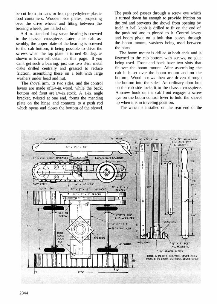
be cut from tin cans or from polyethylene-plasticfood containers. Wooden side plates, projectingover the drive wheels and fitting between thebearing wheels, are nailed on.
A 4-in. standard lazy-susan bearing is screwedto the chassis crosspiece. Later, after cab as-sembly, the upper plate of the bearing is screwedto the cab bottom, it being possible to drive thescrews when the top plate is turned 45 deg. asshown in lower left detail on this page. If youcan't get such a bearing, just use two 3-in. metaldisks drilled centrally and greased to reducefriction, assembling these on a bolt with largewashers under head and nut.
The shovel arm, its two sides, and the controllevers are made of 3/4-in. wood, while the back,bottom and front are 1/4-in. stock. A 1-in. anglebracket, twisted at one end, forms the mendingplate on the hinge and connects to a push rodwhich opens and closes the bottom of the shovel.
The push rod passes through a screw eye whichis turned down far enough to provide friction onthe rod and prevents the shovel from opening byitself. A ball knob is drilled to fit on the end ofthe push rod and is pinned to it. Control leversand boom pivot on a bolt that passes throughthe boom mount, washers being used betweenthe parts.
The boom mount is drilled at both ends and isfastened to the cab bottom with screws, no gluebeing used. Front and back have two slots thatfit over the boom mount. After assembling thecab it is set over the boom mount and on thebottom. Wood screws then are driven throughthe bottom into the sides. An ordinary door bolton the cab side locks it to the chassis crosspiece.A screw hook on the cab front engages a screweye on the boom-control lever to hold the shovelup when it is in traveling position.
The winch is installed on the rear end of the
2344

boom mount. There should be enough clearancebetween the winch drum and the boom mountso the drum can move endwise permitting a boltat the end of the crank to slide between two pinson the boom mount to lock the winch. Nyloncord is fastened to the drum and is provided withan S-hook made of No. 11 -ga. wire, for easyattachment to objects to be pulled. When not inuse the cord is wound up on the drum and theS-hook is clipped in a screw eye on the cab.
It is advisable to partly disassemble the unitfor painting. The chassis is flat black; the treadsand dummy wheels are aluminum and the sideplates red. The cab is red as are the handles ofthe control levers. The rest of the levers areblack, as are the doors, windows, boom mountand the ventilating grille, which is cut from ordi-nary screen and tacked in place.
2345