june 18, 2010 the focus issue 74 june 18, 2010 a ......june 18, 2010 the focus issue 74 2...
TRANSCRIPT

June 18, 2010 The Focus Issue 74
www.padtinc.com 1 1-800-293-PADT
June 18, 2010 A Publication for ANSYS Users Issue 74
By Eric Miller
If you are reading this article you are either a practitioner of Computer AidedEngineering or you are stuck on a desert island and this is the only thing you haveto read. Let's assume the former. If you boil down why your company doesCAE, you should come to one or both of the following reasons: to reduce yourcosts for physical prototyping and/or to increase the number of design iterationsthrough the use of virtual prototypes. Study after study, even ones not paid forby CAE software companies, show that leading companies use more CAE,earlier in the design cycle. Figure 1 shows the results of one such study fromthe Aberdeen Group.
You may be new to CAE, or a 20+ year user. Either way, how does your company maximize the return from their investment in you,your co-workers, the software and the hardware? And do not forget that annual maintenance fee you pay. PADT's internal experienceand lessons learned from our customers, leads us to recommend that the best way to get the most out of that investment
ANSYS supports several of the common techniques used to analyze cracks. In atypical first analysis, an engineer assumes a flaw shape and size and then uses thestress results from an FEA model as input into NASGRO. If a more detailedsimulation is required, an FEA model with a crack included can be created.
There are a few guidelines for using ANSYS to model cracks, the guidelines willbe demonstrated through an example of a steel turbine wheel, shown in Figure 1,which has been assumed to have a crack introduced during the balancing process.A link to the geometry model (v12 UP20090415) and APDL command files areprovided at the end of this article in order to allow the user to reproduce thisanalysis step by step.
In this Issue...
1........Maximizing the ROI on yourCAE Investment
1........Part 2: Modeling Cracks withANSYS
5........Thin Sweep: Sweeping AwaySweep Mesh Restrictions
9........Banishing the Bad GeometryBlues with Design Modeler
8........Training Schedule
11......About PADT
Part 2
ModelingCracks with
ANSYSYou do an article on crack modeling, andyou have to go with the classic “fat guys
on a stool” pictures. No Choice.
Maximizing the ROI onyour CAE Investment
(Cont. on pg. 7)
Instead of using cheesy graphics with money bags, scales,and overly attractive “employees” in meetings, we decided todress up this article with pictures from around Arizona. This isfrom the top of Four Peaks, the mountains east of Phoenix.
(Cont. on pg. 2)
Issue 74, the Last “Magazine” Style Issue of The FocusIt is hard to believe that the next issue of The Focus will be the 75th! We hope you have enjoyed reading it as much as we haveenjoyed making it. As we prepared this issue we came to the realization that this format has served its purpose and that variousInternet based publishing tools have matured to the point where it is time to make a change. We are leaning towards more of ablog approach where we put out single articles once every other week or so, instead of the big issue.
So look for a lot of changes to how we publish and distribute The Focus in the coming months. And thank you again for everyone'scontinued support of this publication!
June 18, 2010 The Focus Issue 74
www.padtinc.com 2 1-800-293-PADT
is to focus on four key aspects of CAE: goals, people, tools, and process. In thisarticle we will talk about each and how to make each aspect work for you.
GoalsIf you have every read an article or attended a seminar hosted by PADT on beingmore efficient/productive you will always hear us start off with goals. We feelthat a lack of clear goals is a huge productivity killer. We find again and againthat companies or teams that successfully use CAE have clear goals for theirentire CAE effort. Goals that they develop, document, and modify as needed.As an example, PADT's CAE goal is: To answer questions raised in productdevelopment in the most cost effective manner with the proper level of accuracyand detail. It may not roll of the tongue but it gets the job done and helps keepus from going off track.
Just as every organization should have goals for their total CAE effort, theyshould also get into the habit of forming goals for each CAE task they undertake.This does not need to be formal but should at least address what you want fromthe calculations you are doing and how accurate they need to be. You shouldwrite them out, kind of like a customer specification and they should never be longer than one sentence. Once they are written downthey can help the engineers involved in the middle of the project, and will help new engineers understand why they are doing the CAEtasks that they have been assigned. Example task goals could be:
· Determine cooling hole size and distribution to obtain required wafer cool down in between 45 and 60 seconds· Report LCF and HCF life based upon customer supplied loading specification· Modify antenna design to minimize material costs and meet signal strength requirements in ES 123.31· Determine min, max and average percent enobarnotopital to provide a between 95% and 99% probanotinaium yield
If the tasks are part of a major effort, it might not be a bad idea to review them weekly. Making goal setting and review part of yourCAE culture can have a huge impact — keeping projects on focus, under budget and most importantly, delivering the information thatthe design team actually wants.
PeopleIt is hard to understate the importance of people in making a CAE effort asuccess, a failure, or just so-so. From key super users to engineers who are inover their heads, people are the most important aspect of getting the most out ofyour CAE investment. They are also the hardest to control.
Dig deep into companies that are true CAE superstars — time and time againyou will find one or more key users. Some call them gurus, some are calledpower users, and still others are simply referred to as simulation gods. We preferthe less charged term "key users." They prove that one person can make adifference by pushing technology and applying it properly. They also helpmanagement make smart tool decisions. Most importantly they mentor, train,and serve as examples for the other users in the organization. Sometimes thesekey users are simply users, sometimes they are managers or members of methodsteams. Regardless of where they come from they share some common charac-teristics:
· Balance between theory and practical· Creative, willing to experiment and try different ways· Fast thinkers· Obsessed with efficiency· Learn things quickly with minimal input· Good at programming/scripting· Involved in real world applications· Strong computer skills
If you are a key user, embrace it and work to help make your organization better. If you are a manager or user who sees the need, workto grow key users by identifying them and encouraging them to take on a strong role. Then focus on keeping them engaged in keyactivities and decisions. Doing so will be one of the best investments any organization can make.
(ROI, Cont...)
(Cont. on pg. 3)
A picture from Sedona looking up to the Red Rocks. Noticethe reflection in the pool. This is a required shot for all visi-
tors to Sedona.
Oak Creek Canyon is one of the green oases that we go nutsfor here. People back east have this sort of thing in their
backyard but for us it is a big deal.

June 18, 2010 The Focus Issue 74
www.padtinc.com 3 1-800-293-PADT
On the other end of the spectrum, and just as powerful, is the anti-particle to thekey user — the bad user. We would like to live in a world where "everyone gets atrophy" but in the real world some people should not be involved in computer aidedengineering. A few are bad users by nature. They are generally too practical or tootheoretical. They also do not remember steps in a process or have a lack of concernabout speed. Lastly they are often not computer experts and get stuck a lot,struggling with solving problems independently. The key thing is to find peoplelike this and take them out of CAE. There are plenty of other engineering tasks outthere that may be a better fit for this type of person.
However, the more common bad user is not bad by nature, they are bad by nurture.A perfectly capable engineer can do a rotten job at CAE because their company didnot use them properly. Typical problems are not enough training, spreading themtoo thin or not giving them the compute horsepower they need. It is also commonto not allow them to do CAE often enough to be good at it. Even if those problemsdo not exist you can get bad results by giving people unreasonable schedules,unrealistic expectations or punishing them for delivering bad news. The good thing about someone who is a bad user because of externalinfluence is that you can flip them into being a good user by removing the negative parts of their environment.
In talking about key users and bad users, we have left out the largest group of users - the mainstream day to day engineers who do thebulk of the CAE work. Because they are the largest group, it is important to remain focused on them. Make sure your organizationmaximizes your considerable investment in them by making some key commitments like giving them the proper hardware and softwarethat they need. Then provide them the time to learn those tools, clear goals, and encouraging them to work together and share theirknowledge and skill.
In short, focus on your people and they will deliver for you. Encourage the truly capable and nurture the average users. And do not beafraid to move those who are not a good match for CAE out of the area.
ToolsWhen people think about CAE, most of the time they focus on tools. Hardware and software are cool, always getting better and fun toevaluate. But, they also cost a bit so companies need to be smart about how they choose and use their CAE tools.
It is obvious that hardware tools (computers) are an essential part of CAE. Even though this is obvious, many companies often makehorrible mistakes in choosing and setting up their hardware. Users end up with machines that struggle to solve their problems. A majorcause of this is IT departments that have no understanding of CAE. It is up to your CAE team to educate them to recognize that yourneeds are different. And eventually convince them to proactively help you.
When purchasing hardware for running numerical simulations it is important to make the right decisions. The most important is to makesure you have more speed, memory and disk storage than you think you will need. This is because no matter how much you think youneed, you will need more. Saving a few hundred, or even thousand dollars on a computer can end up costing your company tens if nothundreds of thousands in schedule delays or reduced accuracy. Along those lines, it is also important to not get too hung
The Editor for ANSYS APDL UsersPeDAL is a Windows text editor for ANSYS APDL scripts. It integrates with the ANSYS helpsystem to provide instantaneous help on any one of the 1,000s of ANSYS commands. PeDALwas written by Matt Sutton, an Engineer at PADT, to make his own job easier. Matt has yearsof experience writing APDL scripts and has long wished for a tool that would provide help fora given command right at his fingertips. Pedal can be purchased for $49 by pressing on theBuy Pedal button below.
Key Features� Side-by-side editor and help viewer layout.� Instant help on any documented APDL command by pressing F1.� Full syntax highlighting for ANSYS v12 Mechanical APDL.� Auto-complete drop downs for APDL Commands.� APDL Command argument hints while typing commands.� Mouse hover command descriptions.� Much More...
Download your 30 day free trial or learn more details at:www.padtinc.com/pedal
(ROI, Cont...)
Up in Northern Arizona on the Navajo Nation there arethese incredible slot canyons. Cut by wind and water,
the way the light shines down is incredible.
(Cont. on pg. 4)

June 18, 2010 The Focus Issue 74
www.padtinc.com 4 1-800-293-PADT
The Focus is a periodic publication of Phoenix Analysis & Design Technologies (PADT). Its goal is to educate and entertain the worldwideANSYS user community. More information on this publication can be found at: http://www.padtinc.com/epubs/focus/about
(ROI, Cont...)
(Cont. on pg. 5)
up just on speed. Often times capacity ismore important than raw compute speed.Look at the overall time it takes to run jobsincluding file transfers, I/O to disk, beingable to run in core and actual CPU speed.
In larger organizations PADT recommendsa tiered approach to hardware: good largedesktops, departmental servers for mediumsized jobs and a corporate cluster if you needto solve lots of problems or big ones. Thisgives your team greater flexibility and pro-vides the right machine for different jobs.Another suggestion is to work closely withyour IT department to make sure they under-stand that you cannot use a "standard build."We see many of our customers hamstrung by the fact that they can only get a machine that is a PLM or CAD standard box and it doesnot have the RAM or disk capacity needed for their analysis.
Software for CAE is the one area the usually gets a lot of focus, and it deserves it. But not just for the CAE software itself. It is importantto also focus on utility software that leverages your CAE software and makes your users more productive. As an example, werecommend that all CAE users have access to a CAD tool or some sort of geometry translate/repair tool. Often times the tool imbeddedin your CAE software is not powerful enough and waiting on someone from the CAD group can kill a schedule.
Other utility software that every user should have include:
· MS Office - do not waste time trying to get some other office tool to work. Just suck it up, pay Microsoft their blood money,and be productive
· Text Editor - Invest in a good text editor for looking at output files, writing scripts, and viewing text information. These don'tcost much and getting a nice one can save hours every month.
· Image Editor - Making pretty pictures is a large part of a CAE user's time. Not having a good image tool can waste hours innon-value added fiddling trying to get pictures just right. Get PaintShop Pro, Photoshop, Gimp or some other tool and learn howto use it.
· Virtual Meeting Tool - Share your data easily and quickly with your customers, support provider and co-workers with a tool likeWebEx, iLinc, or go2Meeting
· Linux Shell on Windows, Virtual Windows on Linux - If you have a multi-OS environment, invest in emulators so you are notalways working around the system.
ProcessLast but certainly not least is process. One of the problems with CAE is that there are so many different ways to solve a problem, andthey all involve detailed steps so it is easy to lose your way. Taking the time to establish standard processes can avoid reinventing thewheel. They keep users on task, allow productivity gains to be captured, and provide a great guide to new or occasional users. The mostimportant benefit of having well documented process is the repeatability of the work.
Like a lot of good things, an organization can go way overboard in this area. Processes need to be flexible and adaptable to real worldcircumstances. Our experience is that if a company has rigid processes, engineers often "go rogue" simply out of spite. A goodcompromise is to standardize the steps in the ideal process in detail, and give guidelines for the overall process. This allows users toreuse what applies and adapt as needed. That same experience has taught us one more thing about the effective use of processes - theyare most effective in companies where a person who is reasonable but strong willed is given the authority to collect, maintain and enforceprocesses.
General RecommendationsThese four areas of focus should help any organization that uses CAE be more efficient and get more value from their CAE investment.Think: GOALS, PEOPLE, TOOLS, PROCESS and try and not focus on the minute details of applying CAE. Also, try and focus on thethings you can change. Goals are the easiest but if you can make changes to your people, that may deliver the best results. Try and getyour whole organization, users, project engineers, management, thinking about CAE as a tool instead of as a black box or a magic bullet.
Another recommendation that we have seen generate good results is to build a positive relationship with your IT team. We have seencompanies that fight with their IT, get nowhere, and end up not having the compute resources they need to be efficient.
You can’t show pictures of Arizona without one of our spectacular sunsets
June 18, 2010 The Focus Issue 74
www.padtinc.com 5 1-800-293-PADT
(ROI, Cont...)And when something goes wrong it takes forever to get back ontrack. Take the time to work with IT, letting them know what youplan on doing way ahead of time. Also, take the time to understandwhat they do. If you can do these things and build a strong personalrelationship with them and maybe even help them out every once ina while, you will get greater efficiency and less down time.
A similar recommendation is to get to know your internal andexternal technical support providers and build a good relationshipwith them. Recognize the fact that providing tech support is a hardjob with little thanks. If you go out of your way to appreciate whatthey do for you, the result will be an extra effort from the supportprovider to make you successful. Lastly, do not cheap out, pay yourmaintenance fees.
The last recommendation that PADT usually makes is the hardest tomake happen. In company after company we see people using thewrong tools, using tools in the wrong way, and wasting time onarguing about tools because some of the engineers get "religious"about their CAE tools. They need to remember that they are engi-neers doing calculations to solve problems, not ANSYS or NASTRAN jockeys. To stretch the analogy even further, when you starthaving faith in your tools, it is time for a reality check. A healthy dose of skepticism is important to making sure you get the most outof your CAE investment.
Next StepsThe first step in maximizing your ROI in CAE is to first recognize that you need to do things to maximize it. The next step is to identifyyour goals and document them. Work on getting the proper people involved and make sure you have the right tools and your users knowhow to use them. Then identify and document some flexible processes.
Looking at this as a bigger picture, the key aspect turns out to be changing the way your company thinks about CAE. In every area listedabove it really boils down to not treating simulation as a black box but as a powerful tool that needs to be used properly by the properpeople. Once you make this change, work on getting your organization to understand the value of CAE and to treat it as a strategic asset.When you look back on the efforts you have made to improve your use of CAE, the biggest change you should see is that you are nowdriving most of your designs efficiently and accurately with simulation.
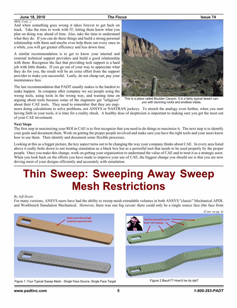
By Jeff StrainFor many versions, ANSYS users have had the ability to sweep mesh extrudable volumes in both ANSYS "classic" Mechanical APDLand Workbench Simulation Mechanical. However, there was one big caveat: there could only be a single source face (the face from
This is a place called Boulder Canyon. It is a fairly typical desert can-yon with stunning rocks and endless vistas.
(Cont. on pg. 6)
Thin Sweep: Sweeping Away SweepMesh Restrictions
Figure 1: Your Typical Sweep Mesh - Single Face Source, Single Face Target Figure 2 Bwuh?? How'd he do dat?
June 18, 2010 The Focus Issue 74
www.padtinc.com 6 1-800-293-PADT
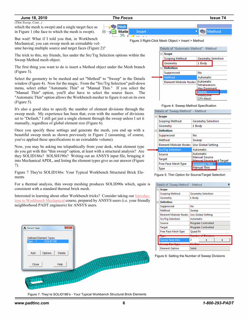
which the mesh is swept) and a single target face asin Figure 1 (the face to which the mesh is swept).
But wait! What if I told you that, in WorkbenchMechanical, you can sweep mesh an extrudable vol-ume having multiple source and target faces (Figure 2)?
The trick to this, my friends, lies under the Src/Trg Selection options within theSweep Method mesh object.
The first thing you want to do is insert a Method object under the Mesh branch(Figure 3).
Select the geometry to be meshed and set "Method" to "Sweep" in the Detailswindow (Figure 4). Now for the magic. From the "Src/Trg Selection" pull-downmenu, select either "Automatic Thin" or "Manual Thin." If you select the"Manual Thin" option, you'll also have to select the source faces. The"Automatic Thin" option allows the Workbench mesher to figure it out on its own(Figure 5).
It's also a good idea to specify the number of element divisions through thesweep mesh. My experience has been that, even with the number of divisionsset to "Default," I still get just a single element through the sweep unless I set itmanually, regardless of global element size (Figure 6).
Once you specify these settings and generate the mesh, you end up with abeautiful sweep mesh as shown previously in Figure 2 (assuming, of course,you've applied these specifications to an extrudable volume).
Now, you may be asking me telepathically from your desk, what element typedo you get with this "thin sweep" option, at least with a structural analysis? Arethey SOLID186s? SOLSH190s? Writing out an ANSYS input file, bringing itinto Mechanical APDL, and listing the element types give us our answer (Figure7).
Figure 7 They're SOLID186s: Your Typical Workbench Structural Brick Ele-ments
For a thermal analysis, thin sweep meshing produces SOLID90s which, again isconsistent with a standard thermal brick mesh.
Interested in learning about other Workbench tricks? Consider taking our Introduc-tion to Workbench Mechanical course, prepared by ANSYS users (i.e. your friendlyneighborhood PADT engineers) for ANSYS users.
Figure 5: Thin Option for Source/Target Selection
Figure 6: Setting the Number of Sweep Divisions
Figure 7: They’re SOLID186’s - Your Typical Workbench Structural Brick Elements
(Thin Sweep, Cont...)
Figure 4: Sweep Method Specification
Figure 3 Right-Click Mesh Object > Insert > Method

June 18, 2010 The Focus Issue 74
www.padtinc.com 7 1-800-293-PADT
Part 1 of this article in the previous issue of The Focus covered the use of KCALC andthe steps used to prepare a mesh for its use. Recent versions of ANSYS have addedcommands to simplify the process. Refer to Part 1 for details of the model creation. Themeshing scheme is similar with the exception that we use solid186 and solid187 insteadof solid95 and solid92.
Figure 2 shows the mesh, note that the wedge elements at the crack tip need to have themidside nodes moved to the 1/4 radius location. This creates the stress singularity neededto properly model the stress distribution seen in a crack front.
A baseline model was first run without a crack. The S1 result from that run is shown inFigure 3. Maximum S1 shown is equal to 28.4 ksi.
The model was then run with a 0.020in deep crack. Maximum S1 shown in Figure 4 isequal to 79.6 ksi.
Issue CINT,TYPE,JINT prior to solution for ANSYS to calculate the J-integrals. If youissues a CINT,TYPE,SIFS prior to solution, ANSYS will calculate the Stress IntensityFactors (K1, etc).
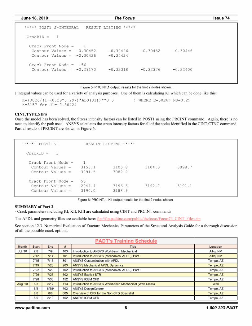
CINT,TYPE,JINTOnce the model has been solved, the J-integral can be listed in POST1 using the PRCINT command. One advantage of using PRCINTinstead of KCALC is that you no longer need to identify the path used. ANSYS calculates the J-integral for all of the nodes identifiedin the CINT,CTNC command. Partial results of PRCINT are shown in Figure 5. This example used 6 contours (CINT,NCON,6) sothere are 6 values calculated. Each contour represents a calculation including that "number of rings of elements". In other words,contour number 3 includes 3 rings of elements when integrating the path around the crack.
Figure 1: Fictitious Turbine Wheel Analyzed
Figure 2: Meshed model, red=solid187, purple=solid186, elements at the crack tip have the midside nodes
Figure 3: S1 plot of the model without a crackFigure 4: S1 plots of the model with a 0.020in crack
(Crack, Cont...)
June 18, 2010 The Focus Issue 74
www.padtinc.com 8 1-800-293-PADT
J integral values can be used for a variety of analysis purposes. One of them is calculating KI which can be done like this:
K=(30E6/(1-(0.29*0.29))*ABS(J1))**0.5 ! WHERE E=30E6; NU=0.29K=3157 for J1=-0.30424
CINT,TYPE,SIFSOnce the model has been solved, the Stress intensity factors can be listed in POST1 using the PRCINT command. Again, there is noneed to identify the path used. ANSYS calculates the stress intensity factors for all of the nodes identified in the CINT,CTNC command.Partial results of PRCINT are shown in Figure 6.
SUMMARY of Part 2- Crack parameters including KI, KII, KIII are calculated using CINT and PRCINT commands
The APDL and geometry files are available here: ftp://ftp.padtinc.com/public/thefocus/Focus74_CINT_Files.zip
See section 12.3. Numerical Evaluation of Fracture Mechanics Parameters of the Structural Analysis Guide for a thorough discussionof all the possible crack options.
***** POST1 J-INTEGRAL RESULT LISTING *****
CrackID = 1
Crack Front Node = 1 Contour Values = -0.30452 -0.30426 -0.30452 -0.30446 Contour Values = -0.30436 -0.30424
Crack Front Node = 56 Contour Values = -0.29170 -0.32318 -0.32376 -0.32400
Figure 5: PRCINT,1 output, results for the first 2 nodes shown.
***** POST1 K1 RESULT LISTING *****
CrackID = 1
Crack Front Node = 1 Contour Values = 3153.1 3105.8 3104.3 3098.7 Contour Values = 3091.5 3082.2
Crack Front Node = 56 Contour Values = 2944.4 3196.6 3192.7 3191.1 Contour Values = 3190.0 3188.9
Figure 6: PRCINT,1,,K1 output results for the first 2 nodes shown
PADT’s Training ScheduleMonth Start End # Title LocationJul '10 7/8 7/9 103 Introduction to ANSYS Workbench Mechanical Albq, NM
7/12 7/14 101 Introduction to ANSYS (Mechanical APDL), Part I Albq, NM7/15 7/16 801 ANSYS Customization with APDL Tempe, AZ7/19 7/20 203 ANSYS Mechanical APDL Dynamics Tempe, AZ7/22 7/23 102 Introduction to ANSYS (Mechanical APDL), Part II Tempe, AZ7/26 7/27 502 ANSYS Explicit STR Tempe, AZ7/28 7/30 152 ANSYS ICEM CFD Tempe, AZ
Aug ‘10 8/3 8/12 113 Introduction to ANSYS Workbench Mechanical (Web Class) Web8/5 8/58/ 702 ANSYS DesignXplorer Tempe, AZ8/6 8/6 605 Overview of CFX for the Non-CFD Specialist Tempe, AZ8/9 8/10 152 ANSYS ICEM CFD Tempe, AZ
June 18, 2010 The Focus Issue 74
www.padtinc.com 9 1-800-293-PADT
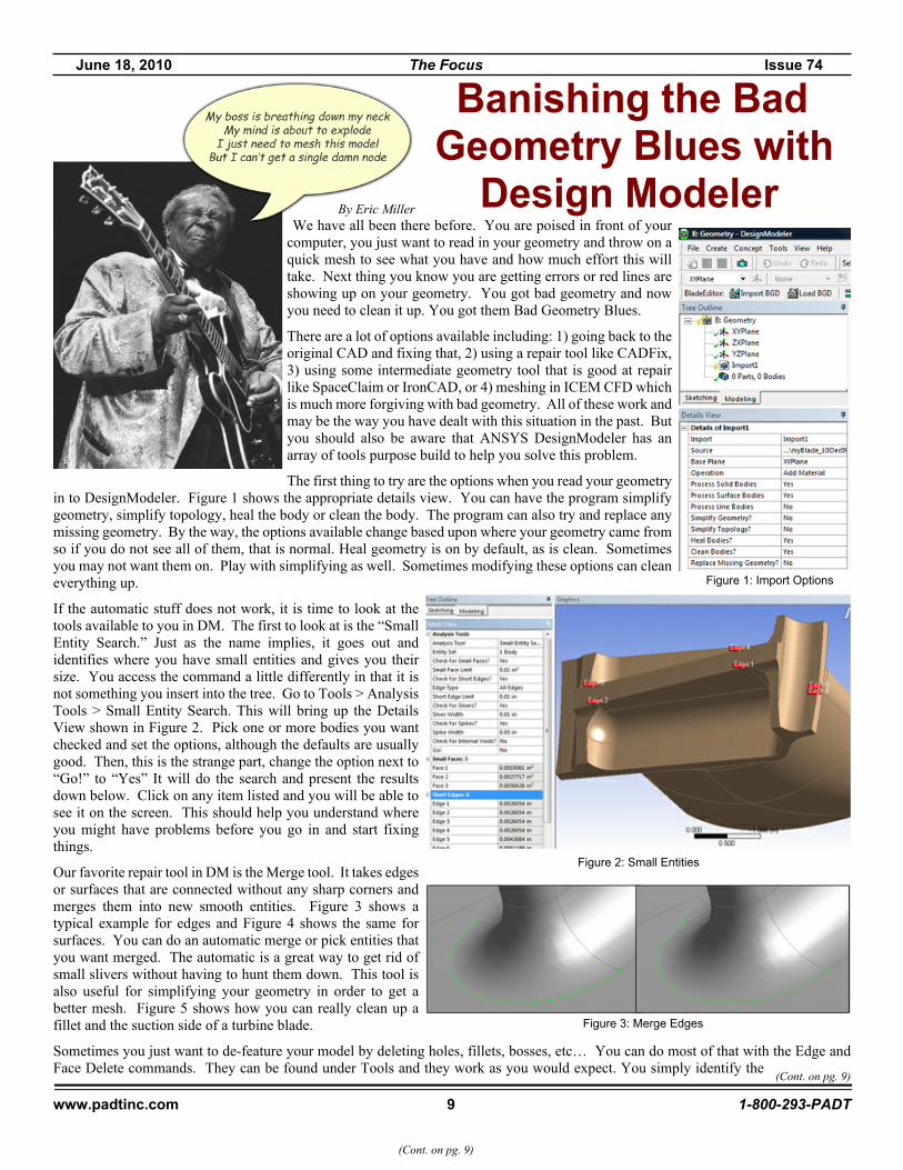
By Eric MillerWe have all been there before. You are poised in front of your
computer, you just want to read in your geometry and throw on aquick mesh to see what you have and how much effort this willtake. Next thing you know you are getting errors or red lines areshowing up on your geometry. You got bad geometry and nowyou need to clean it up. You got them Bad Geometry Blues.
There are a lot of options available including: 1) going back to theoriginal CAD and fixing that, 2) using a repair tool like CADFix,3) using some intermediate geometry tool that is good at repairlike SpaceClaim or IronCAD, or 4) meshing in ICEM CFD whichis much more forgiving with bad geometry. All of these work andmay be the way you have dealt with this situation in the past. Butyou should also be aware that ANSYS DesignModeler has anarray of tools purpose build to help you solve this problem.
The first thing to try are the options when you read your geometryin to DesignModeler. Figure 1 shows the appropriate details view. You can have the program simplifygeometry, simplify topology, heal the body or clean the body. The program can also try and replace anymissing geometry. By the way, the options available change based upon where your geometry came fromso if you do not see all of them, that is normal. Heal geometry is on by default, as is clean. Sometimesyou may not want them on. Play with simplifying as well. Sometimes modifying these options can cleaneverything up.
If the automatic stuff does not work, it is time to look at thetools available to you in DM. The first to look at is the “SmallEntity Search.” Just as the name implies, it goes out andidentifies where you have small entities and gives you theirsize. You access the command a little differently in that it isnot something you insert into the tree. Go to Tools > AnalysisTools > Small Entity Search. This will bring up the DetailsView shown in Figure 2. Pick one or more bodies you wantchecked and set the options, although the defaults are usuallygood. Then, this is the strange part, change the option next to“Go!” to “Yes” It will do the search and present the resultsdown below. Click on any item listed and you will be able tosee it on the screen. This should help you understand whereyou might have problems before you go in and start fixingthings.
Our favorite repair tool in DM is the Merge tool. It takes edgesor surfaces that are connected without any sharp corners andmerges them into new smooth entities. Figure 3 shows atypical example for edges and Figure 4 shows the same forsurfaces. You can do an automatic merge or pick entities thatyou want merged. The automatic is a great way to get rid ofsmall slivers without having to hunt them down. This tool isalso useful for simplifying your geometry in order to get abetter mesh. Figure 5 shows how you can really clean up afillet and the suction side of a turbine blade.
Sometimes you just want to de-feature your model by deleting holes, fillets, bosses, etc… You can do most of that with the Edge andFace Delete commands. They can be found under Tools and they work as you would expect. You simply identify the
Banishing the BadGeometry Blues with
Design Modeler
(Cont. on pg. 9)
Figure 2: Small Entities
Figure 1: Import Options
Figure 3: Merge Edges
(Cont. on pg. 9)
June 18, 2010 The Focus Issue 74
www.padtinc.com 10 1-800-293-PADT
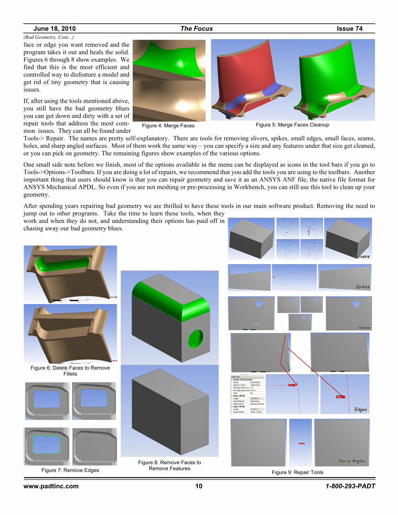
face or edge you want removed and theprogram takes it out and heals the solid.Figures 6 through 8 show examples. Wefind that this is the most efficient andcontrolled way to disfeature a model andget rid of tiny geometry that is causingissues.
If, after using the tools mentioned above,you still have the bad geometry bluesyou can get down and dirty with a set ofrepair tools that address the most com-mon issues. They can all be found underTools-> Repair. The names are pretty self-explanatory. There are tools for removing slivers, spikes, small edges, small faces, seams,holes, and sharp angled surfaces. Most of them work the same way – you can specify a size and any features under that size get cleaned,or you can pick on geometry. The remaining figures show examples of the various options.
One small side note before we finish, most of the options available in the menu can be displayed as icons in the tool bars if you go toTools->Options->Toolbars. If you are doing a lot of repairs, we recommend that you add the tools you are using to the toolbars. Anotherimportant thing that users should know is that you can repair geometry and save it as an ANSYS ANF file, the native file format forANSYS Mechanical APDL. So even if you are not meshing or pre-processing in Workbench, you can still use this tool to clean up yourgeometry.
After spending years repairing bad geometry we are thrilled to have these tools in our main software product. Removing the need tojump out to other programs. Take the time to learn these tools, when theywork and when they do not, and understanding their options has paid off inchasing away our bad geometry blues.
(Bad Geometry, Cont...)
Figure 4: Merge Faces Figure 5: Merge Faces Cleanup
Figure 6: Delete Faces to RemoveFillets
Figure 7: Remove EdgesFigure 8: Remove Faces to
Remove FeaturesFigure 9: Repair Tools
June 18, 2010 The Focus Issue 74
www.padtinc.com 11 1-800-293-PADT
In the past we have finished up The Focus with a page we called “Shameless Advertising...”The truth was that the page was really only advertising PADT, and PADT related things. So,instead of doing advertising we thought we would just dedicate the final page to explainingwho PADT is, what we do and how we can hopefully help you. And, to make sure you readit, we will try and stick something funny in. Want to know more? Call Stephen Hendry at207-333-8780 or e-mail [email protected].
Humor: Why the Chicken Crossed the Road... In the Words of the Star Wars Characters(www.maniacworld.com/star_wars_jokes/Star_Wars_Jokes.html)
Rapid PrototypingDid you know that PADT, Inc. is one of the most respected Rapid Prototyping servicebureaus in the world? For 16 years, since the founding of the company, PADT’s RPgroup has been providing high quality prototype parts to customers around the world.
In that time the RP market has changed, and most small service bureaus have long since been gobbled up by larger firms or just plaingone out of business. But PADT has held our own by providing a high level of technical expertise and customer focus - similar towhat has made the company a leader in the ANSYS world.On site we have machines that use the three leading technologies: Photolithography, Fused Deposition Modeling, and Selective LaserSintering. We also have a CNC mill and lathe, hand finishing tools, and a full paint booth so we can create that perfect part thatcustomers expect. The same team also provides soft tooling (rubber molding) and injection molding for when you need to movebeyond prototypes. Next time you need a prototype, please consider having PADT provide a quote.Visit the rapid manufacturing part of our web site (www.padtinc.com/rm) or e-mail [email protected] to learn more.
PADT on the Webwww.PADTINC.com PADT’s main website
www.PADTMedical.com Medical device developmentwww.DimensionSCA.com A machine that PADT makes
www.PADTMarket.com A place to buy 3D Printers & Supplieswww.XANSYS.org ANSYS User forum
Need ANSYS Help?PADT can help in many different ways, here are a few:
� We hold training here or at your facility <link>
� Leverage our APDL knowledge with the APDL Guide <link>
� Consider one-on-one support through mentoring, a greatway to get a quick start on something new <link>
� Attend a PADT Webinar <link>Join us on Facebook!
Search for PADT, Inc. and become a fan!
VADER: Because it could not resist the power of the Dark Side.YODA: Crossing the road makes not a chicken great.LUKE: I want to follow the ways of the chicken and cross the road like myfather.LEIA: I don't know... but I have a bad feeling about this.HAN: Hurry up, colonel sanders, or you're gonna be a permanent resi-dent!THREEPIO: I am fluent in over six million ways of crossing the road.BEN: Cross the road, chicken. Let go, chicken. Chicken - trust me.
BIGGS: At that speed, will you be able to cross in time?TARKIN: The regional governors now have direct control over theirchickens. Fear will keep those chickens in line... fear of getting hit by acar!ADMIRAL ACKBAR: All chickens - prepare to cross the road on my markLANDO: Why you slimy, no good, double-crossing chicken!! You got a lotof guts crossing that road, after what you pulled!EMPEROR: Young fool. Only now, after getting hit by a car do youunderstand.JABBA: Bo shuda chicken!