juliosilva - portfolio - rev1
TRANSCRIPT

JULIO SILVA
ELECTRICAL ENGINEER

JULIO SILVA – WORK PORTFOLIO 22
1. Electrical Motor Drilling GD-120 1.1. Portfolio Details
Company Companhia Vale do Rio Doce Site Sossego’s mine (Mina do Sossego)
Year 2005 Motivation Issue Report
1.2. Introduction This report aims to try to elucidate the possible reasons that led to the Rotor of Direct Current Rotation motor of Drilling GD-120 (2002) burns.
1.3. Problem Description The operator and shift facilitator reported the motor failure, with the presence of electric arc engine. When photographing the motor rotor could be proved that, it showed cracks in its periphery, compromising the structure thereof. This can be seen in the figures below:
Figure 1.1 - Cracks along the DC rotation motor
In addition, it has been observed, according to the reading of the meter drive motor drive, which time the "burning" of the rotor happened, there were high values of current in the motor armature. This event reminds us of a possible event: the torque of the motor burned, "slave", migrated to a very high value. In this way we will describe this phenomenon to validate this placement and propose some possible causes for the same. 1.4. Operation of the integrated system with motors
Both engines work in master slave system, with the central pinion rotary head, with the engine in green on the right is the engine "Master" and the engine in question, the green of the left engine, is the "slave" motor. The centre circle in yellow is the central pinion rotary head.
JULIO SILVA – WORK PORTFOLIO 33
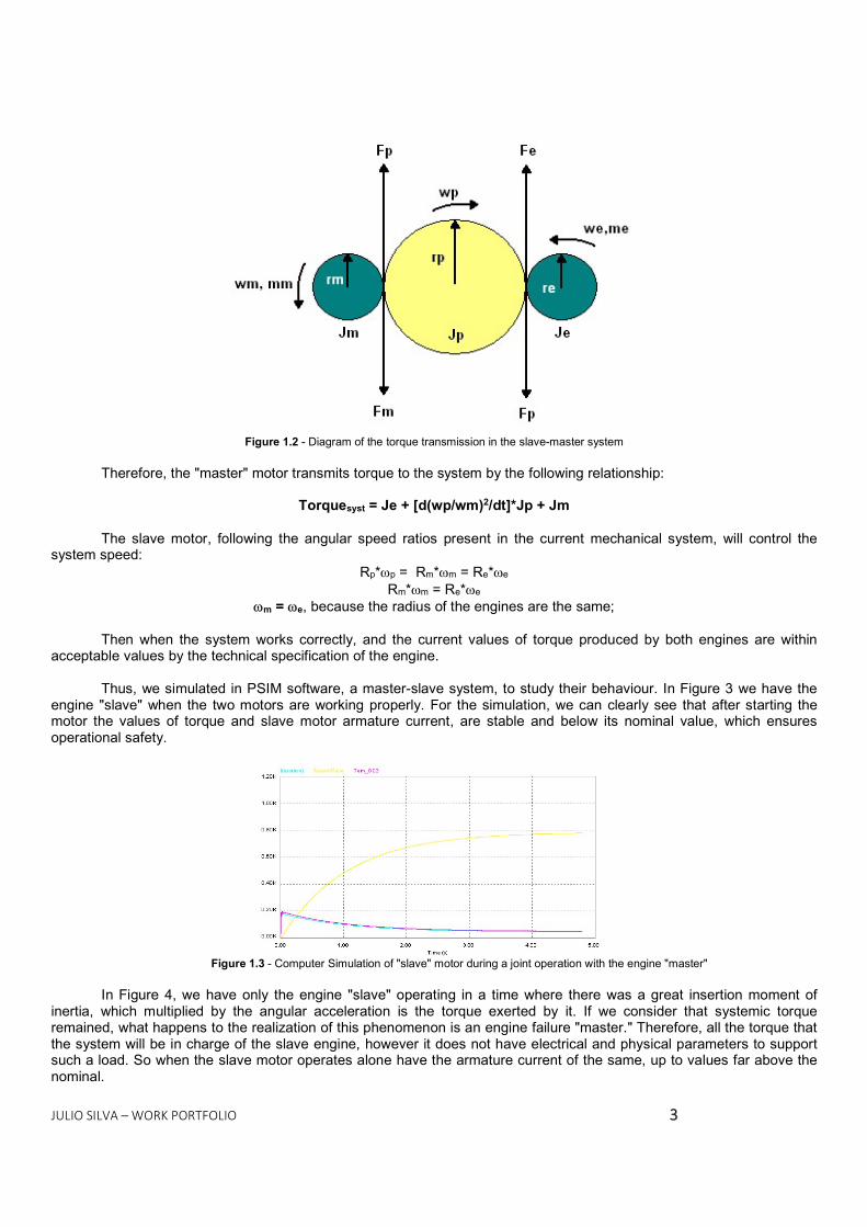
Figure 1.2 - Diagram of the torque transmission in the slave-master system Therefore, the "master" motor transmits torque to the system by the following relationship:
Torquesyst = Je + [d(wp/wm)2/dt]*Jp + Jm
The slave motor, following the angular speed ratios present in the current mechanical system, will control the system speed: Rp*p = Rm*m = Re*e
Rm*m = Re*e m = e, because the radius of the engines are the same; Then when the system works correctly, and the current values of torque produced by both engines are within
acceptable values by the technical specification of the engine.
Thus, we simulated in PSIM software, a master-slave system, to study their behaviour. In Figure 3 we have the engine "slave" when the two motors are working properly. For the simulation, we can clearly see that after starting the motor the values of torque and slave motor armature current, are stable and below its nominal value, which ensures operational safety.
Figure 1.3 - Computer Simulation of "slave" motor during a joint operation with the engine "master" In Figure 4, we have only the engine "slave" operating in a time where there was a great insertion moment of
inertia, which multiplied by the angular acceleration is the torque exerted by it. If we consider that systemic torque remained, what happens to the realization of this phenomenon is an engine failure "master." Therefore, all the torque that the system will be in charge of the slave engine, however it does not have electrical and physical parameters to support such a load. So when the slave motor operates alone have the armature current of the same, up to values far above the nominal.

JULIO SILVA – WORK PORTFOLIO 44
Figure 1.4 - Computer Simulation of "slave" motor with the master off Armature current is proportional to torque, independent of voltage and motor speed. So, we can normalize the
current values and torque generated during typical connections in order to generate a safe range of DC motors operation: -0,2 (Tl/To) (Ia/Iao) 0,2
Where: Tl - torque produced by the engine; E - Nominal torque; Ia - instant armature current; Iao - nominal armature current;
In addition, if we assume that the standard current and torque values are equal, we got the following operating region in yellow:
Figure 1.5 - Operating Bandwidth DC motors It is expected that the motors to operate within this band of operation to thereby achieve the same balancing
operation rate of armature voltage which is -1Ua/Uao1 where Ua is the instantaneous motor voltage, and is a UAO nominal voltage. When a voltage outside this range is generated in the armature is sparking the motor brushes, leading switch failed the same and short-circuit training in brushes, a phenomenon we call flashover.
1.5. Conclusions That is for a described phenomenon that occurred with the engine removed from the Drilling Machine 2002, which
has been necessary that the torque exerted by the same value, exceeds the operating band associated with the current. As the value of the torque exerted during the correct operation of the rotating head, has operational security, we came to the conclusion that one of the possible factors for this sudden increase in torque is the engine failure "master" during drilling.
1.6. Propositions for solution of this issue and future problems of overload

JULIO SILVA – WORK PORTFOLIO 55
The contactor K1 is controlled by the motor drive of each drive, and a fuse make the protections on the motor armature, which is located before K1. Both the contactor and the fuse are shown in Figure 6, which is the wiring diagram of the motor drive. As the nominal current of the equipment is 182 A and considering that the drive has an overshoot of 60% can scale a 300A fuse protection, but remembering that it still has extensive protection area.
Now what we found the machine is a fuse 500 A, figure 7 and 8. This fuse may not be providing protection for the drive motor armature to be over dimensioned for the same.
Figure 1.6 - Electrical scheme of rotation Drive
Figure 1.7 - Motor drive - the circle is where the fuse500A

JULIO SILVA – WORK PORTFOLIO 66
Figure 1.8 - Fuse Zoom with specifications

JULIO SILVA – WORK PORTFOLIO 77
2. Reliability quantification based on failure rate for mining equipment 2.1. Portfolio Details Company Companhia Vale do Rio Doce
Site Sossego’s mine (Mina do Sossego) Year 2006
Motivation Paper presented on 61o ABM Congress 2.2. Summary
The Sossego’s Mine, producer of copper concentrate, is a mining which produces an average of 400,000 tons / year of concentrate. Currently has 6 Drilling Machines with an average production rate of 16,43 m / h, and 3 Rope Shovels (71 yd3), an average rate of 3100 tbn / h, these equipment have the main function ensuring the movement of about 4,000,000 tons / month in the mine. As the fleet is relatively small, all equipment have a very marked impact on mine production, so the physical availability of them must have high values with little change during the year. Therefore, this study aims to estimate reliability alerts for these machines to aid in the formulation of maintenance plans, regarding Reliability Centre on Maintenance. 2.3. Development
2.3.1. Description of Failures For the acquisition of a reliable database containing data relating to failures in the excavator 4100 XPB and GD-
120 drill, we will use the electronic dispatch of the Sossego’s mine and so we came to a description of how they behave failures in existing equipment:
2.3.2. Shovel 4100 XPB
Figure 2.1 – Failures Pareto of Shovel 4100XPB

JULIO SILVA – WORK PORTFOLIO 88
Thus, the set of excavation is the one that most infers the unavailability of equipment. Moreover, the main cause of failures on that is the adapters, the Tooth Cover and Latches, all parts of the bucket. In addition, we have the electrical components, which account for 13% of the charts Excavator 4100 XPB and the drive drum Lifting system by another 11%. 2.3.3. Drilling Machine GD-120
Figure 2.2 – Pareto Failure of Drilling DD-120 In Drilling’s Pareto, we divided the unavailability in the main subsets, according to Pareto done through the
maintenance history data obtained by the electronic dispatch of the Sossego mine. Therefore, we have to the rotary head (which are encompassed by the engines even beyond the system that connects and sustains) the unavailability caused by the same is 45%, and power and control system of the drilling rig (which are included, locomotion engine, electrical panels, control drivers, etc...), the unavailability is that it contributes 43%. Once inserting RCM alerts, we hope to reduce the mean time between failure (MTTF) occurred in subsets of which we are working, so as to diminish the general MTTF of the machines in the cumulative average. Through the historical generated by machines, we have daily values of physical availability achieved by the machines, through this value, we will calculate the global lifetimes of our machines, and use Paretos values that we have shown above. As the mine dispatch does not give us the inherent availability of the equipment, only the availability achieved, we propose the following hypothesis to give beginning to our reasoning:
MTTF = MTBF Mean time to failure = Mean Time between Maintenance Corrective and Preventive
We will make this approach because the intention of this article is to get a great point in preventive maintenance,
but to decrease the rate of corrective maintenance, so the MTTF and MTBF tend to similar values. The MTTF of the machines will be given by:
1)(1 rifi ttNMTTF
Equation <1> Therefore, the idea is to reduce the rate of failure to thereby increase our MTTF and thus increase our reliability
for each machine in question. 2.3.4. Study of the performance of the machines concerning their failure rates of the analysed sub-
systems According to the Pareto made for the two machines we assume that all components of both machines (excavator
4100 XPB and Drilling GD-120) they are mutually independent. Therefore, we will use the Markov method to analyse the failure interactions. Thus, we will define as will behave fault combinations and operation of the components, which form part of the proposed system for each machine. Thus, the goal is to calculate the probability from a state i at a time t,

JULIO SILVA – WORK PORTFOLIO 99
promoting changes in failure rates, caused by the insertion of the supervisory systems and thus to measure the hypothetical gains in availability and reliability of our equipment. For this, we have the reliability over time for the systems that we are proposing will be:
oii tPtR
Equation <2> To determine the Pi(t) values, which are the probability of a system switches from one operating state to a fault
stat, we will use using differential equations, one for each state of the proposed system, referring to the state transitions. Thereby calculate the probability that a component will fail between a state t and t + t. Thus, it will develop faults interaction diagram for the equipment in question analysed. 2.3.5. Shovel 4100XPB At Pareto raised, we have much of the physical reliability and availability of the machine is given by the following subsystems: Excavation, Force and Hoist, so we will build your fault interaction diagram, but for this you need to build a table with all possible failure interactions:
1 2 3 4 5 6 7 8ShovelPowerHoist
Markov's Table
OperatingFailureSubtitle >>>
4100XPB ShovelComponents States
Table 1 – Markov’s Table for Shovel 4100 XPB As the machine depends both on the operation of the three systems, we can assume that the combination that the
alloy is in series, so when one of the systems fails we have the equipment will assume the failed state.
Figure 2.3 - Block Diagram for Excavator 4100XPB So, we will have our transition map:

JULIO SILVA – WORK PORTFOLIO 1100
Figure 2.4 - Transition Map for Failures in the Shovel 4100 XPB Where according to the table and delivery done in the excavator we will have: e+ele+f = 0, 031 e - Failure rate for excavation = 0.022 f - Failure rate for power = 0.004 ele - failure rate for hoist = 0,005 Thus, we have the differential equations for the proposed map
1
87654321
00000000000000000000000000000000000000000000000000000000)(*4
P
PPPPPPPP
dtd
elefefele
eleefe
elef
eelefe
Equation <3> Solving the differential equation above and applying the relationship with the reliability, we got the following
relationship:
4)( 031,0009,0027,0026,0005,0004,0022,0124,0 tttttttt eeeeeeeetR Equation <4>

JULIO SILVA – WORK PORTFOLIO 1111
Figure 2.5 – Shovel’s Function Reliability Clock failure rate for a period of 720 h (one month 24/7) Through computer simulation for 720h, we have the alarm values for Shovel, what occurs approximately at the
time 328h, i.e., on the 14th day. Thus, it would launch a low-reliability alarm on the machine to the planning team of maintenance, which goes into the RCM premises.
2.3.6. Drilling GD-120
Keeping the same think applied to excavator 4100 XPB, we will raise all interactions caused by the sub-systems that were considered key in drill GD-120, so we have:
1 2 3 4
Markov's TableDrilling Machine GD-120
Subtitle >>> OperatingFailure
Power and ControlRotary Head
Components States
Table 2 Likewise, the two systems are arranged in series, or if any of the sub-assemblies fail, lead to drill failure.
Figure 2.6 - Block Diagram for Excavator 4100XPB This made the transition map is with the following provision:

JULIO SILVA – WORK PORTFOLIO 1122
Figure 2.7 - Failure of Transition Map for Drilling GD-120
Where in accordance with the table and the Pareto made for the Drilling we will have: cr+f = 0, 050 cr - failure rate for rotary head = 0.022 f - Failure rate for power and control = 0,021 Thus, we have the following equations for the proposed map:
1
4321
000000000000)(*2
PPPPP
dtd
fcrf
crfcr
Equation <4> Solving the differential equation above and applying the relationship with the reliability, we got the following
relationship: 1)( 43,021,022,086,0 tttt eeeetR
Equation <5>
Figure 2.8 - Function Reliability Clock failure rate for a period of 720 h (one month 24/7)

JULIO SILVA – WORK PORTFOLIO 1133
As in 4100XPB Shovel, we have function reliability clock failure rate for Drilling GD-120, where the alert is in 70 hours or 3 days.
2.4. Conclusion
Through the simulations produced, it is clear that small variations in the failure rate provide big gains in reliability and physical availability. However, due to fewer interactions and greater weight of the subsystems, the alarm value for the Drilling is much smaller than the Shovel’s. However, the estimate here has another preamble; reliability values for both devices are very low when compared to benchmark values from other mines: Excavator (450h for Alarm) and Drilling even worse when compared (350h for Alarm).

JULIO SILVA – WORK PORTFOLIO 1144
3. Collision Avoidance System 3.1. Portfolio Details
Company SKM Consulting Site Adelaide Terrace
Year Motivation
2010 Project S11D – Iron Ore Project
3.2. Introduction The purpose of this document is to describe the implementation of the Collision Avoidance System (CAS) under Schneider Modicon/Citect on the SKM HLS Prototype developed for Vale. The intent is to provide detailed information on design configuration in the event that the original developers are not available when any future development occurs.
The CAS is primarily responsible for preventing mobile machines from colliding into each other during normal operation. It is also responsible for helping operators avoid putting mobile machines into situations where in normal operation they may trip to prevent collision.
The CAS is algorithmic logic that uses positioning information from the machines to mathematically determine minimum distance between machines, collision zones and stockpile areas where multiple machines working together should be avoided. The CAS has built-in safeguards to limit the movement of machines in the event that an instrument responsible for critical collision prevention has failed.
The CAS system developed on the SKM HLS Prototype for Vale is designed around four mobile machines in the Product Yard. These machines include two slewing stackers and two slewing reclaimers, with the reclaimers sharing a common rail. With these four machines, it is possible to simulate all the potential collision scenarios.

JULIO SILVA – WORK PORTFOLIO 1155
3.3. PLC Configuration
The basic flow of the CAS PLC program can be seen in the figure below.
Figure 3.1 - CAS PLC Flowchart

JULIO SILVA – WORK PORTFOLIO 1166
3.3.1. Initialise Machine Models This section in the PLC initializes the machine model by hard-coding all the coordinates into the respective machine model array. The coordinates are based on the machine being positioned at 0m Long Travel, 0° Slew and 0°
Luff. In the PLC, the coordinates are stored in a 100-element array of data type CASPointDDT. This section also initializes the array of Groups used throughout the program. Each group contains information on whether a particular area on the machine is able to slew or luff, along with relative slew and luff adjustments. 3.3.2. Mobile Machine Data
The Long Travel, Slew and Luff position information is read by the CAS PLC via communications paths. The mobile machines also communicate status bits to the CAS PLC indicating the health of the encoders for Long Travel, Slew and Luff. Mobile machine data is stored in the data type CASFromMMDDT. The system is designed to use dual encoders for each machine movement. Since it is imperative that the positional information is accurate, any faults with the devices that report the position of the machine must be handled accordingly. For example, when a Long Travel encoder faults, and the machine is running on a single encoder, the allowable protection distance doubles. 3.3.3. Update Model Positions
The actual machine model coordinates are relative to an imaginary datum point with the coordinates (0,0,0). In the Product Yard, this is in the South-West corner of the stockyard. Each point on the machine is offset in the X and Y direction according to its Long Travel and Rail Offset respectively. Each point is then translated onto the XYZ plane according to the machine’s current travel, slew and luff position. 3.3.4. Exclusion Zones
Exclusion zones are activated on a machine whenever there are faults with Long Travel, Slew or PLC communications. The exclusion zones are derived from the PLC section Calculate_Exclusion_Zones.
For a Long Travel exclusion zone, the machine is enveloped in a rectangular zone, which covers the entire length of the stockyard. The width of the rectangular zone depends on the slew angle of the machine, as the distance between the rail and the farthest points of the machine will increase as the machine slews further away from its park position.
A slew exclusion zone is made up of segments to form a circular shape around the machine. On the HMI it appears as a perfect circle, however in reality it is a 20-sided polygon. The size of each segment is determined by the slew radius of the machine, which is calculated based on a point on the boom, which is the farthest point from the centre of slew.
If there is a communications fault between the CAS and the mobile machine, or if the machine reports a fault in both long travel and slew positioning systems, then the worst case is assumed. The exclusion zone covers the entire length of the yard, and extends out either side of the rail at the length of the slew radius.
Each zone is defined as a series of points and stored in an array of CASPointDDTs, so it is identical to a mobile machine model. This enables the distance calculation algorithm to function as normal; the only difference is the model is a different shape to a regular mobile machine (i.e. a rectangle or circle). 3.3.5. Calculate Minimum Distances Calculating Horizontal Distance (2D)
Each machine pair uses an instance of the CALC_DIST block to determine the minimum distance between them. The block uses the machine model arrays, the current working quadrant and exclusion zone information to output the minimum distance and the corresponding X and Y coordinates.
Note: this block only calculates a two-dimensional distance using the X and Y axis. The CALC_DIST_3D block also calculates a two-dimensional distance; however, it uses the Y and Z axes only..
The machine model connected to the MachineModel1 pin should be the adjacent machine to the north of MachineModel2. The machine models used to calculate the distance could be the actual machine model, the rectangular exclusion zone model, or the circular exclusion zone model. The section Determine_Model is used to decide which model is used in the calculation.

JULIO SILVA – WORK PORTFOLIO 1177
Figure 3.2 - Determine Model flowchart
The working quadrant number is used to compare only a subset of the points used in the model. For example, if stacker EP01 is working in quadrant 3 and reclaimer RC01 is working in quadrant 1, their booms will be in the same
canyon. Thus, it is necessary to only compare the points around the boom, as these are the only parts of the machine capable of colliding. This reduces overhead on the PLC.
Figure 3.3 shows a flowchart of the algorithm used for the CALC_DIST function block.

JULIO SILVA – WORK PORTFOLIO 1188
Figure 3.3 - Algorithm used for finding minimum distance
Calculating Vertical Distances (3D) For the system to calculate the minimum vertical height between machines, certain conditions need to be met. The machines need to be operating in a quadrant that could result in a boom-to-counterweight collision. There must be healthy communications between the CAS and mobile machine PLCs The luff system must be healthy on both machines

JULIO SILVA – WORK PORTFOLIO 1199
For each machine pair, the 3D Collision Detection Enabled tag is used to mask the 3D collision alarm, as well as enable the function block CALC_DIST_3D which determines the minimum vertical distance. This block won’t necessarily calculate the minimum distance between current closest points; rather it looks along the whole length of the yard to determine if the machine can pass by another machine without tripping.
As mentioned previously, the vertical distance calculation looks at Y and Z coordinates only. By comparison, the minimum horizontal distance is calculated as if the machines were viewed from a top-down plan perspective. The vertical distance is calculated as if the machines were viewed from a side elevation perspective. The algorithm for calculating the minimum vertical distance is identical to Figure 3.3.
3.3.6. Collision Alarms A collision alarm is generated when the minimum distance between machines is less than the minimum protection distance. There are three types of alarms:
Collision warning – when the minimum horizontal protection distance is breached. Collision alarm – When the emergency horizontal protection distance is breached. Vertical collision warning – when a collision warning is active, and the minimum vertical distance is
breached. The alarm logic uses the INDLIM_REAL block, such that to reset the alarm the machines must be farther than the
protection distance + 5% apart. See Figure 3.4 for sample logic for collision alarms between stacker EP01 and reclaimer RC01.
In the prototype, the following constants are used for the protection distances. MIN_PROT_DIST_U Minimum collision protection
distance (horizontal) 10.0m
MIN_EMRGCY_DIST_U Minimum collision emergency distance
5.0m
MIN_PROT_VERT_DIST_U Minimum collision protection vertical distance
10.0m
MIN_SNGL_DIST_U Minimum single-encoder collision protection distance
20.0m
A coll ision warning is raised if the closest distance between the machines is less than the minimum protection distance. To reset the warning, the machines must be separated by the minimum protection distance + 5%.A vertical col l ision warning is raised if the vertical and horizontal protection distances are breached, and '3D' mode is enabled. A col l ision alarm is raised if the EMERGENCY DISTANCE is breached.
IN3IN1EP01_RC01_COLL_WIN2EP01_RC01_3D_EN OUT EP01_RC01_VERT_COLL_W
.19AND 12
IN1MIN_SNGL_DIST_UGIN0MIN_PROT_DIST_U OUT
.20SEL 2 IN1
IN21.05 OUT
.21MUL_REAL3
MX_LOWMN_LOW
XEP01_RC01_DISTMX_HIGH
MN_HIGH
MX_INDMN_IND
FBI_64INDLIM_REAL 4
IN1MIN_EMRGCY_DIST_UIN21.05 OUT
.22MUL_REAL7
MX_LOWMN_LOW
XEP01_RC01_DISTMX_HIGH
MN_HIGHMIN_EMRGCY_DIST_U
MX_INDMN_IND
FBI_65INDLIM_REAL 8
MX_LOWMN_LOW
XEP01_RC01_VERT_DISTMX_HIGH
MN_HIGHMIN_PROT_VERT_DIST_U
MX_INDMN_IND
FBI_66INDLIM_REAL 11
IN1MIN_PROT_VERT_DIST_UIN21.05 OUT
.23MUL_REAL10
IN3RC01_ZT01_SNGL_ENC01IN4RC01_ZT02_SNGL_ENC01
IN1EP01_ZT01_SNGL_ENC01IN2EP01_ZT02_SNGL_ENC01 OUT
.24OR 1
IN1IN2
OUT EP01_RC01_COLL_W
.9AND 6
IN3EP01_SAFE_ZONEIN4RC01_SAFE_ZONE
IN1EP01_SRV_SIN2RC01_SRV_S OUT
.14AND 5
IN1IN2
OUT EP01_RC01_COLL_A
.15AND 9
Figure 3.4 - Collision Alarm PLC Logic
JULIO SILVA – WORK PORTFOLIO 2200
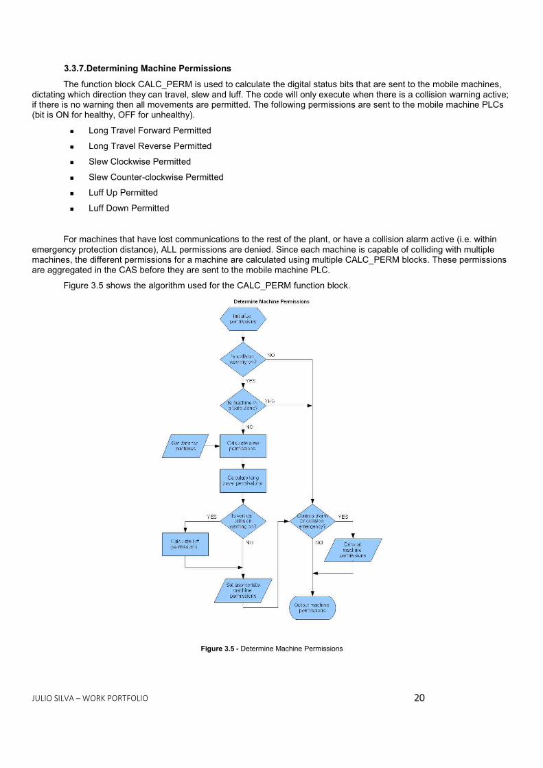
3.3.7. Determining Machine Permissions The function block CALC_PERM is used to calculate the digital status bits that are sent to the mobile machines,
dictating which direction they can travel, slew and luff. The code will only execute when there is a collision warning active; if there is no warning then all movements are permitted. The following permissions are sent to the mobile machine PLCs (bit is ON for healthy, OFF for unhealthy).
Long Travel Forward Permitted Long Travel Reverse Permitted Slew Clockwise Permitted Slew Counter-clockwise Permitted Luff Up Permitted Luff Down Permitted
For machines that have lost communications to the rest of the plant, or have a collision alarm active (i.e. within emergency protection distance), ALL permissions are denied. Since each machine is capable of colliding with multiple machines, the different permissions for a machine are calculated using multiple CALC_PERM blocks. These permissions are aggregated in the CAS before they are sent to the mobile machine PLC.
Figure 3.5 shows the algorithm used for the CALC_PERM function block.
Figure 3.5 - Determine Machine Permissions

JULIO SILVA – WORK PORTFOLIO 2211
3.3.8. Permission Alarms When a collision warning is active, and permissions are denied to a machine, an alarm is generated for each type
of permission movement which is denied. This is done in the Machine_Permission_Alarms section, where the aggregated permissions word is reversed (i.e. a logical NOT is performed) to generate the alarms. 3.3.9. Queue Due to the nature of the CAS, the program is quite resource hungry on the PLC. Thus measures have been taken
to reduce the number of calculations done in one PLC scan. The CALC_QUEUE block maintains a queue that dictates which calculations can be executed. Each of the major
function blocks (CALC_POSN, CALC_ZONES, CALC_DIST, CALC_DIST_3D) have input pins for determining when each block will execute.
The input pins used are: Calc_Set – An integer used to identify a block instance. Queue – An integer, which corresponds with the first item in the queue.
When the first item in the queue (as seen by the Queue input) matches the Calc_Set number of a function block, the block will run. Multiple blocks can have the same Calc_Set number; which means that more than one block will execute in the same scan. Care must be taken in having multiple blocks executing, so as not to overload the controller. During prototyping, the scan time for the CAS PLC was 130 – 150ms.
The queue acts as a FIFO stack and is stored as a 40-element array. On every scan, the first item in the queue is cleared and all the elements are shifted up by one. Elements are added to the queue based on their communications status; for example, when the CAS PLC retrieves new data from a mobile machine PLC, or there is a communications error, then all the blocks associated with that PLC should run.
In the prototype, the “new data” pulses are simulated since the individual mobile machine PLCs don’t exist. In a real plant, the communications logic should trigger a successful read pulse, which in turn should add an item to the queue for processing.
See the table below for a list of the Calc_Set numbers and their corresponding machines\machine pairs.
Calc_Set Machine 1 EP01 2 RC01 3 RC02 4 EP02 10 EP01 -> RC01 3D 11 EP01 -> RC02 3D 12 RC01 -> EP02 3D 13 RC02 -> EP02 3D
3.3.10. Bump Turnaround The Bump Turnaround is a digital status bit sent to the mobile machine PLCs, but it is only can be required for the
Stackers. The status bit will remain ON for 5 seconds while the machines are in a state that requires a Bump Turnaround. Figure 6 below shows the current conditions for a Bump Turnaround.

JULIO SILVA – WORK PORTFOLIO 2222
EP01 Bump Turnaround logicThe Bump Turnaround signal is held up for 5s, to enable the signal to be read over comms before resetting.
IN1EP01_RC01_COLL_XIN2RC01_EP01_COLL_X OUT
.1SUB_REAL1
IN OUT
.2ABS_REAL2
IN1IN2
OUT
.3LT_REAL4
IN1MIN_PROT_DIST_UIN210.0 OUT
.4ADD_REAL3
IN1IN2RC01_SAFE_ZONE OUT
.5AND 5
IN1EP01_RC02_COLL_XIN2RC02_EP01_COLL_X OUT
.6SUB_REAL6
IN OUT
.7ABS_REAL7
IN1IN2
OUT
.8LT_REAL9
IN1MIN_PROT_DIST_UIN210.0 OUT
.9ADD_REAL8
IN1IN2RC02_SAFE_ZONE OUT
.10AND 10
IN1IN2
OUT
.11OR 11
INPTSYS_5s_U Q EP01_BMP_TRN_REQ
ET
FBI_41TOF 13
CLK Q
FBI_43R_TRIG12
Figure 3.6 - Bump Turnaround PLC logic
The relative mobile machine PLC will contain logic to check if the Stacker is stacking as part of a sequence, as well as handle the direction and maximum number of Bump Turnarounds, as the CAS does not do this.
3.3.11. YMS Collision Avoidance When the user requests custody of a stockpile, the new Work Zone is compared to existing Work Zones and
checked for any overlaps. If the new Work Zone overlaps, a message is sent back to the HMI and appropriately, informative text is displayed on the screen.
Figure 3.7 shows the workflow for managing this process.
Figure 3.7- YMS Collision Avoidance

JULIO SILVA – WORK PORTFOLIO 2233
3.3.12. Inter-PLC Communications The CAS communicates with both the Mobile Machine PLCs and the YMS. For information on the interface
between the CAS and Mobile Machine PLCs, see the interface document TESP ET-6071KS-J-70564 HLS Interface. The data between these PLCs will align with the workflow intended for the YMS Collision Avoidance. Preliminary design has been done and can be found in the data type YMSMMDataDDT in the CAS PLC. 3.3.13. SSC Interface
The screenshot below shows the CAS overview screen from the Citect prototype.
LEGEND: 1. EP01 Stacker, with faulted Long Travel and Slew drives 2. RC01 Reclaimer, with faulted Long Travel and Slew drives 3. EP01 and RC01 text showing collision alarm status 4. Machine position information 5. Machine CAS alarms 6. Permission fault status 7. RC02 showing “Safe Zone” status 8. Collision information for EP01 to RC01 collision 9. Table shows 3D distances (vertical distances between machines) and 3D enabled status 10. “Out of Service” SSC command buttons
1
2
3
4 4 4 4
5 5 5 5
6 6
7
8
9 10

JULIO SILVA – WORK PORTFOLIO 2244
3.3.14. Supporting Information Data Structures CASFromMMDDT
Data sent from the mobile machines to the CAS. TAG SUB-TAG TYPE DESC ZT01 REAL Long Travel Position ZT02 REAL Slew angle ZT03 REAL Luff Angle STS CASMMStsDDT Machine Status Bits ZT01SENC BOOL Long Travel Single Encoder Mode Enabled ZT01DENC BOOL Long Travel Dual Encoders Healthy ZT02SENC BOOL Slew Single Encoder Mode Enabled ZT02DENC BOOL Slew Dual Encoders Healthy ZT03SENC BOOL Luff Single Encoder Mode Enabled ZT03DENC BOOL Luff Dual Encoders Healthy LOCBYP BOOL Local CAS Bypass Enabled
CASToMMDDT
Data sent from the CAS to the mobile machines TAG TYPE DESC LTFWD BOOL Long Travel Forward Permitted LTREV BOOL Long Travel Reverse Permitted SLCW BOOL Slew Clockwise Permitted SLCCW BOOL Slew Counter-clockwise Permitted LFUP BOOL Luff Up Permitted LFDN BOOL Luff Down Permitted BMPTRN BOOL Stacker Bump Turnaround Required
CASPointDDT
Defines a cartesian coordinate in the (x,y,z) plane. TAG TYPE DESC GRP INT The group that this point belongs to XCRD REAL X coordinate of the cartesian coordinates YCRD REAL Y coordinate of the cartesian coordinates ZCRD REAL Z coordinate of the cartesian coordinates CON1 INT Array index position of the first point that connects to this one CON2 INT Array index position of the second point that connects to this one CON3 INT Array index position of the third point that connects to this one
JULIO SILVA – WORK PORTFOLIO 2255
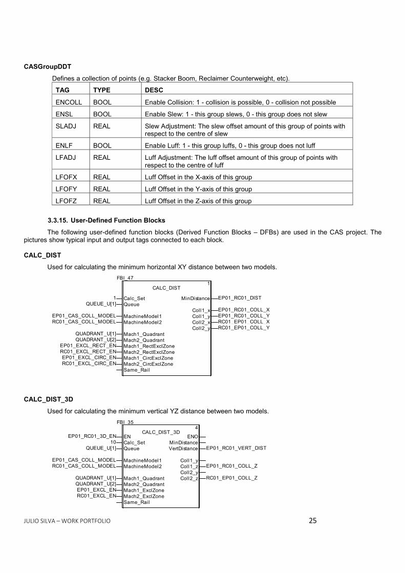
CASGroupDDT
Defines a collection of points (e.g. Stacker Boom, Reclaimer Counterweight, etc). TAG TYPE DESC ENCOLL BOOL Enable Collision: 1 - collision is possible, 0 - collision not possible ENSL BOOL Enable Slew: 1 - this group slews, 0 - this group does not slew SLADJ REAL Slew Adjustment: The slew offset amount of this group of points with respect to the centre of slew ENLF BOOL Enable Luff: 1 - this group luffs, 0 - this group does not luff LFADJ REAL Luff Adjustment: The luff offset amount of this group of points with
respect to the centre of luff LFOFX REAL Luff Offset in the X-axis of this group LFOFY REAL Luff Offset in the Y-axis of this group LFOFZ REAL Luff Offset in the Z-axis of this group
3.3.15. User-Defined Function Blocks The following user-defined function blocks (Derived Function Blocks – DFBs) are used in the CAS project. The
pictures show typical input and output tags connected to each block. CALC_DIST
Used for calculating the minimum horizontal XY distance between two models.
Mach1_CircExclZoneEP01_EXCL_CIRC_EN
MachineModel2RC01_CAS_COLL_MODEL
Mach2_QuadrantQUADRANT_U[2]
QueueQUEUE_U[1]
Mach2_RectExclZoneRC01_EXCL_RECT_ENMach2_CircExclZoneRC01_EXCL_CIRC_EN
Mach1_RectExclZoneEP01_EXCL_RECT_ENMach1_QuadrantQUADRANT_U[1]
MachineModel1EP01_CAS_COLL_MODEL
Same_Rail
Calc_Set1
Coll2_y RC01_EP01_COLL_Y
Coll1_x EP01_RC01_COLL_XColl1_y EP01_RC01_COLL_Y
MinDistance EP01_RC01_DIST
Coll2_x RC01_EP01_COLL_X
FBI_47CALC_DIST 1
CALC_DIST_3D Used for calculating the minimum vertical YZ distance between two models.
ENEP01_RC01_3D_EN
Same_Rail
MachineModel2RC01_CAS_COLL_MODEL
Mach2_QuadrantQUADRANT_U[2]
QueueQUEUE_U[1]
Mach2_ExclZoneRC01_EXCL_EN Mach1_ExclZoneEP01_EXCL_ENMach1_QuadrantQUADRANT_U[1]
MachineModel1EP01_CAS_COLL_MODEL
Calc_Set10 ENO
Coll2_z RC01_EP01_COLL_ZColl2_yColl1_y
MinDistanceVertDistance EP01_RC01_VERT_DIST
Coll1_z EP01_RC01_COLL_Z
FBI_35CALC_DIST_3D 4

JULIO SILVA – WORK PORTFOLIO 2266
CALC_PERM
Determines the machine permissions based on the relative positions of the machine models, and the status of collision\communications alarms.
Mach1_Travel_PosEP01_ZT01Mach2_Travel_PosRC01_ZT01
Coll1_yEP01_RC01_COLL_Y
Coll2_yRC01_EP01_COLL_Y
Mach2_Rail_OffsetRC01_OFFSETYMach2_QuadrantQUADRANT_U[2]
Mach1_Comms_AlmEP01_PLC_COMMS_F
Coll2_xRC01_EP01_COLL_X
Mach1_ExclZoneEP01_EXCL_EN
Mach2_Comms_AlmRC01_PLC_COMMS_F
Coll_AlarmEP01_RC01_COLL_A
Mach1_Rail_OffsetEP01_OFFSETY
Coll1_xEP01_RC01_COLL_X
Mach1_Safe_ZoneEP01_SAFE_ZONEMach1_QuadrantQUADRANT_U[1]
Coll1_zEP01_RC01_COLL_Z
PiSYS_PI_U
Coll_Vert_WarnEP01_RC01_VERT_COLL_W
Coll2_zRC01_EP01_COLL_Z
Mach2_ExclZoneRC01_EXCL_EN
Coll_WarnEP01_RC01_COLL_W
Mach2_Safe_ZoneRC01_SAFE_ZONE
Mach1_Permissions EP01_CAS_PERM1Mach2_Permissions RC01_CAS_PERM1
FBI_75CALC_PERM 1
CALC_POSN
This is used to update the base machine model so that it matches the actual position of the machine in the stockyard, relative to the datum point.
PiSYS_PI_U
GroupsEP01_CAS_GROUP
Slew_PosEP01_ZT02
QueueQUEUE_U[1]
Rail_OffsetEP01_OFFSETY
Travel_PosEP01_ZT01
Base_ModelEP01_CAS_BASE
Luff_PosEP01_ZT03
Calc_Set1Slew_Radius EP01_EXCL_CIRC_RAD
Actual_Model EP01_CAS_MODELValid
FBI_42CALC_POSN 1
CALC_QUAD Used to update an array of 8 integers with values of the working quadrant of each machine in the stockyard.
SlewAngle3RC02_ZT02 SlewAngle2RC01_ZT02
SlewAngle5EP03_ZT02
SlewAngle8SlewAngle7
SlewAngle4EP02_ZT02
SlewAngle1EP01_ZT02
SlewAngle6RC03_ZT02
QuadrantQUADRANT_U Quadrant
FBI_288CALC_QUAD 1

JULIO SILVA – WORK PORTFOLIO 2277
CALC_QUEUE Manages the Queue used for processing machine model and collision scenario calculations.
ErrorERROR_UQueueQUEUE_UNewDataNEWDATA_U Queue
FBI_5CALC_QUEUE 1
CALC_YMS_LIMIT
Calculates the working zone of each machine based on data received from the YMS.
ENSYS_1s_pulse
Mach4_BaseModelEP02_CAS_BASEPiSYS_PI_U
Mach3_GroupRC02_CAS_GROUP
Mach2_BaseModelRC01_CAS_BASE
Rail_Offset_ArrayRail_Offset_Array_U
Machine_YMSDataYMS_MC_Data_U
Mach3_BaseModelRC02_CAS_BASE
Mach4_GroupEP02_CAS_GROUPMach1_BaseModelEP01_CAS_BASE
Mach2_GroupRC01_CAS_GROUP Mach1_GroupEP01_CAS_GROUP
Empty_PointEMPTY_POINT_U
YMS_GeneralYMS_General_U ENO
Mach2_WorkZone RC01_WORKZONEMach3_WorkZone RC02_WORKZONEMach4_WorkZone EP02_WORKZONE
Mach1_WorkZone EP01_WORKZONE
FBI_39CALC_YMS_LIMIT 9
CALC_ZONES
This block calculates the rectangular and circular exclusion zones, based on the status of the Long Travel, Slew and communications for a machine.
Sle w_R ad iusEP 01 _EX CL _CIR C_ RAD
Com m s_O KE P0 1_P LC_ CO MM S_F
Rai l_O ffse tE P01 _O FFS ETYSle w_O KE P01 _ZT 02 _EN C_F
Qu eueQ UE UE_ U[1 ]
Em pty_ Po intEM PTY _P OIN T_U
PiSY S_P I_U
Cal c_S et
Circ _M ode l EP 01_ EXC L_ CIR C
S ou th_L imi t EP 01_ EXC L_ STH _L MT
E na ble_ Cir c EP 01_ EXC L_ CIR C_E N
Ea st_L imi t EP 01_ EXC L_ EAS T_ LMT
E nab le_ Rec t EP 01_ EXC L_ REC T_ EN
FB I_5 7CA LC_ ZO NES
Slew_RadiusEP01_EXCL_CIRC_RAD
Comms_OKEP01_PLC_COMMS_F
Rail_OffsetEP01_OFFSETY Slew_OKEP01_ZT02_ENC_F
QueueQUEUE_U[1]
Empty_PointEMPTY_POINT_U
PiSYS_PI_UTravel_OKEP01_ZT01_ENC_F
ModelEP01_CAS_MODEL
Travel_PosEP01_ZT01
Calc_Set1
Circ_Model EP01_EXCL_CIRC
South_Limit EP01_EXCL_STH_LMT
Enable_Circ EP01_EXCL_CIRC_EN
West_Limit EP01_EXCL_WEST_LMT
North_Limit EP01_EXCL_NTH_LMT
Rect_Model EP01_EXCL_RECT
East_Limit EP01_EXCL_EAST_LMT
Enable_Rect EP01_EXCL_RECT_EN
FBI_57CALC_ZONES 1
INIT_MODEL
Configure the properties of a point within a machine model.
Connect211
Y_Coord2.0
Connect3
Z_Coord10.12
Group3X_Coord-47.0
Connect12
Point_Data EP01_CAS_BASE[1]
FBI_28INIT_MODEL 1

JULIO SILVA – WORK PORTFOLIO 2288
INIT_GROUP Configure the properties of a group, used to classify the points on a machine model.
Enable_Luff1
Luff_Y_Offset0.0 Luff_X_Offset0.0
Enable_Slew1
Luff_Z_Offset6.85
Luff_Adjustment
Slew_AdjustmentEnable_Coll ision1 Group_Data EP01_CAS_GROUP[1]
FBI_0INIT_GROUP 88
IN1EP01_ZT02IN2-2.0 OUT
.3MUL_REAL85
IN1GEP01_ZT03_DUAL_ENC01IN00.0 OUT
.2SEL 87
IN10.0IN2EP01_ZT03 OUT
.1SUB_REAL86

JULIO SILVA – WORK PORTFOLIO 2299
4. Control of Ore Tonnage at OHP’s Screening House 4.1. Portfolio Details Company HWE Mining
Site Area C Year
Motivation 2008 Design Report 4.2. Introduction
The Screening House area is composed of five belt feeders that remove ore from silo and discharge into screens
classifiers. The passing material of the screens can be discharged into three conveyor belts, the overflow material from the screens goes to two crushers, and the crushed material returns to the Screening House.
OHP SCREENING HOUSE
Bins
Feeders
Screens
MC - go to CrushersMC - LumpMC - Fines
Figure 4.1 – Process diagram of Screening House
4.3. The Control Loop The flow control loop acts on the speed of the feeder controlling the flow on conveyor belts receiving the through
material from the classification screens. Each feeder has a PI control, in which the manipulated variable is the feeder speed, driven by a frequency inverter. The controlled variable is a fraction of the total flow in the belt, calculated according to the position of the derailleurs. The flow is measured on the scale divided by the number of feeders targeted for that belt.
JULIO SILVA – WORK PORTFOLIO 3300
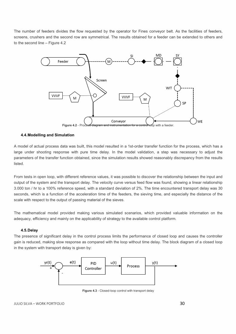
The number of feeders divides the flow requested by the operator for Fines conveyor belt. As the facilities of feeders, screens, crushers and the second row are symmetrical. The results obtained for a feeder can be extended to others and to the second line – Figure 4.2
Figure 4.2 - Process diagram and instrumentation for a control loop with a feeder.
4.4. Modelling and Simulation A model of actual process data was built, this model resulted in a 1st-order transfer function for the process, which has a large under shooting response with pure time delay. In the model validation, a step was necessary to adjust the parameters of the transfer function obtained, since the simulation results showed reasonably discrepancy from the results listed.
From tests in open loop, with different reference values, it was possible to discover the relationship between the input and output of the system and the transport delay. The velocity curve versus feed flow was found, showing a linear relationship 3.000 ton / hr to a 100% reference speed, with a standard deviation of 2%. The time encountered transport delay was 30 seconds, which is a function of the acceleration time of the feeders, the sieving time, and especially the distance of the scale with respect to the output of passing material of the sieves.
The mathematical model provided making various simulated scenarios, which provided valuable information on the adequacy, efficiency and mainly on the applicability of strategy to the available control platform.
4.5. Delay The presence of significant delay in the control process limits the performance of closed loop and causes the controller gain is reduced, making slow response as compared with the loop without time delay. The block diagram of a closed loop in the system with transport delay is given by:
Figure 4.3 - Closed-loop control with transport delay

JULIO SILVA – WORK PORTFOLIO 3311
Delay compensation techniques to propose ways to predict the process output without time delay and feeds it to the controller. The idea of a delay compensator was proposed by Smith (1957) and is often described as a Smith predictor. The compensator is added to a conventional control loop with shown in Figure 4. The shape and positioning compensator remove, effectively, the delay time of the loop dynamics, resulting in a more stable system.
Figure 4.5 - Separation of the transmission process delay block unit 4.6. Results
Performing simulation for control models in Matlab Simulink, PI control and control using the Smith predictor, response graphics to a unit step were obtained for each model, and the comparison between them, as shown in Figures 4.6 to 4.8. The figure 4.9 shows a series combination of the two. The values of the model parameters found by approximation to the real response curve and the simulated response time are shown in Table 1.
Figure 4.6 – The step response curve for the PI controller

JULIO SILVA – WORK PORTFOLIO 3322
Figure 4.7 - Response curve the unit step to the controller with Smith predictor
Figure 4.8 - Response curve to unit step with combined controlled

JULIO SILVA – WORK PORTFOLIO 3333
Figure 4.9 – Response curve to the unit step for the three models
Red - PID Control closed loop.Blue - Control using Smith predictor.
Green - combined control (open loop + closed loop) Control Kp Ki Kd TresponsePI 0,015 0,010 0,000 300Preditor Smith 1,000 0,200 0,000 75Combined 0,015 0,004 0,000 125
Table 4.1 - Parameters of controllers and simulated response time The proposed control system was implemented and it tested in Screening House and the curves were recorded using the existing PI control and the curve after activation of the proposed control, as shown in Figures 4.10 and 4.11. The reduction in the response time was approximately 3 minutes (Table 2).
Figure 4.10 – Plant response curve with existing PI control

JULIO SILVA – WORK PORTFOLIO 3344
Figure 4.11 – Plant response curve using the combined control
Real Simulation
PI 300 300Preditor Smith 120 125
Difference 180 175
Control Response Time
Table 4.2 - Real response time versus simulation
4.7. Conclusion
The proposed control model showed a significant improvement on time response in the Screening House without causing conditions that compromise safety and the permitted operating limits.
Therefore, the proposed control solution can be regarded as a simple, low cost and efficient in reducing the time for system response delay of a dominant transport, since known approximate relationship between the input and output.

JULIO SILVA – WORK PORTFOLIO 3355
5. Solution of Substation Automation System using PLX81 5.1. Portfolio Details
Company Vale Site Cauê’s Mine (Mina do Cauê)
Year Motivation
2014 Design and Test Report
5.2. Objective This report aims to validate the integration solution between IEDs ABB (REx630) and Quantum PLC through PLX81-
MNET-61850 converter. In addition, present the results for the pre-commissioning of this system in a real Substation. 5.3. Procedures and achieved results for the integration Tests
Initially, we have performed tests with a PLX81-MNET-61850 converter. A platform with 1 ABB relay Power
Laboratory Practices and 44 IEDs of Cauê’s Project was mounted a PLX81-MNET-61850 protocol converter, a Cisco IE3000 switch, a computer for monitoring devices and a PLC Quantum with NOE card (Modbus TCP / IP), as illustrated in the figure below:
Figure 5.1 - Network topology used in the test.
22 RET 630 Cauê 22 RET 630
Cauê

JULIO SILVA – WORK PORTFOLIO 3366
Using the converter configuration software ProSoft MNET-61850, the SCD Cauê’s files and IADC LPE were imported:
Figure 5.2 – Importation of the SCD files. After importing the SCD and CID files to the configuration software, the IEDs was added to establish communication:
Figure 5.3 - IED Insertion into the configuration.
The next step was to configure the Modbus TCP / IP device, in this case used the PLC Quantum with NOE card as the following figure:

JULIO SILVA – WORK PORTFOLIO 3377
Figure 5.4 - Modbus device for communication establishment The points to be published by each IED in Modbus TCP-IP network must be mapped by IED, as shown below:
Figure 5.5 - Configuration of the points to be read from the IED The defined memory map for the tests was comprised of 12 writing of words read and 9 (relative to Quantum PLC) for FDI. After performing the mapping of variables in all IEDs, just download logic to the drive:

JULIO SILVA – WORK PORTFOLIO 3388
Figure 5.6 - Uploading the setting for the converter With the converter properly configured, the next step was to export the XSY file for configuration of communication via the PLC Quantum NOE card, as shown below:
Figure 5.7 – XSY File Export

JULIO SILVA – WORK PORTFOLIO 3399
With the XSY file in hand, it held all the necessary settings in the PLC Quantum to establish communication with IEDs through PLX81-MNET-61850. Below are some configuration details:
It was used to perform the IO Scan readings of variables; Reading and writing were conducted in the same word;
The controls are performed only on FDI Power Laboratory Practices. The IEDs Cauê served to simulate the actual
implementation of the project.
For the opening and closing commands the points was used SPC8GGIO1$CO$SPCSO3$Oper$ctlVal and SPC8GGIO1$CO$SPCSO3$Oper$ctlVal respectively.
After some tests it was noted that when the application starts, the Quantum PLC must write 6 in points
SPC8GGIO1$CO$SPCSO3$Oper$origin$orCat e SPC8GGIO1$CO$SPCSO2$Oper $origin$orCat (IEC 61850-7-3). • orCat: The orCat must contain information on the source that caused changes in the value of the signal. Below is
a summary of the values that orCat can take:
Tag Descriptionnot-supported OrCat is not supported.bay-control control operation located bay level.station-control control operation located at station level.remote-control control operation by a remote operator outside the substation.automatic-bay control operation by an automatic function bay level.automatic-station control operation by an automatic function the station level.automatic-remote control operation by an automatic function outside the substation.maintenance control operation by a maintenance / service toolprocess Operation without external control action. Table 5.1 - Description of the values that orCat can take.
Following the philosophy that will be implemented in the project Adequacy Cauê, the Open Breaker command should not have any limitation, whether the IED is in Local or Remote, the operator will always have permission to open the breaker. The Close command will only be released if the IED is in Remote.

JULIO SILVA – WORK PORTFOLIO 4400
Below is the information that IEDs (REM630) sent to the PLC Quantum:
BI Sinal Típico 4.16kV Típico 13.8kVCOM_101.BI1 Circuit breakerCOM_101.BI2 Closed circuit breakerCOM_101.BI3 Test breakerCOM_101.BI4 breaker SetCOM_101.BI5 Extracted breakerCOM_101.BI6 spring LoadedCOM_101.BI7 Def Int Cub NeighborCOM_101.BI8 Local Key (Panel)COM_101.BI9 Remote Key (Panel)COM_101.BI10 Key League (Allows only in test position)COM_101.BI11 SECC ClosedCOM_101.BI12 SECC OpenCOM_101.BI13 Command breakersCOM_101.BI14 reserve
BIO_3.BI1 Emergency buttonBIO_3.BI2 Reservation (Open Door / Local / Lever InsertionBIO_3.BI3 Disj Circ Command (4.16kV) / Equiptos (13.8kV)BIO_3.BI4 Disj Motor Ext and SpringBIO_3.BI5 Disj MM and TPBIO_3.BI6 Switch Off (Allows only in test position)BIO_3.BI7 emergency FieldBIO_3.BI8 Motor Alarm RTDBIO_3.BI9 Motor Trip RTDBIO_4.BI1 Disj TP IEDBIO_4.BI2 reserveBIO_4.BI3 reserveBIO_4.BI4 reserveBIO_4.BI5 reserveBIO_4.BI6 reserveBIO_4.BI7 reserveBIO_4.BI8 reserveBIO_4.BI9 Def Int REA
MVGGIO1 MVGGIO1
MVGGIO2 MVGGIO2

JULIO SILVA – WORK PORTFOLIO 4411
- 27 - undervoltage- 50/51 - Overcurrent- 50/51 GS - Overcurrent Ground Sensor- 37 - Undercurrent- 46 - Current Negative Sequence- 48 - Fail to Start- 49 - Thermal Overload- 66 - Number of Matches exceeded- 50BF - Breaker Failure- 86 - Blocking- reserve- reserve- reserve- reserve- Ready to Open Breaker- Ready to Close Breaker- A current (A) CPHMMXU CPHMMXU
B Current (A) CPHMMXU CPHMMXUC Current (A) CPHMMXU CPHMMXU
- Active Phase (W) Power PWRMMXU PWRMMXU- Energy Supplied Phase (kWh) MVGGIO4 MVGGIO4- Cooling Time A SER DEFINIDO A SER DEFINIDO- Time to Restart Enable A SER DEFINIDO A SER DEFINIDO- Open command SPC8GGIO6 SPC8GGIO6- Open command (Source) SPC8GGIO6 SPC8GGIO6- Open command (Check) SPC8GGIO6 SPC8GGIO6- Close command SPC8GGIO7 SPC8GGIO7- Close command (Source) SPC8GGIO7 SPC8GGIO7- Close command (Check) SPC8GGIO7 SPC8GGIO7- Watchdog command SPC8GGIO8 SPC8GGIO8- Watchdog Command (Source) SPC8GGIO8 SPC8GGIO8- Watchdog Command (Check) SPC8GGIO8 SPC8GGIO8
MVGGIO3 MVGGIO3
It was found that due to the rapid time of operation of the protections, the MVGGIO3 block not sensitized. For protections appear correctly on the system, they will be informed by the IED SRMEMORY block. Below is some data for integration tests:
Response time between the command and reception status: average 1,8s Communication reestablishment time if the PLX leave the network: average 73,3s; Communication reestablishment time if the NOE leave the network: average 65,7s.
5.4. Substation Automation System – Commissioning Tests Local: Mactron (SC) Date: November 2014 Voltage Source: 380V in the Automation Bus and Circuit Breakers 5.4.1. Observed Safety Procedures

JULIO SILVA – WORK PORTFOLIO 4422
The purpose of this topic is to all personnel involved on tests an explanation of general safety procedures that should be followed when working in the pre-commissioned Substations. These procedures are intended to reduce risk of injury and incidents. All the rules below were discussed daily with the personnel involved in the Morning Toolbox meeting. The floor maps of Substation can be seen below:
SUBSTATION MAP
During the tests, the Automation System (SAS) were sourced with 220V. The Rest of Buses were energized with 380V.
Automation Room
Air Con
ditione
d Roo
m
High Voltage VVVF
Low Vo
ltage D
rawers
Low Vo
ltage V
VVF
High V
oltage C
ubicles
Muster Point
Figure 5.8 – Substation Map Evacuation When evacuating the building, follow strictly the arrows in the Substation Map. It is mandatory that all personnel go to the Muster point in events, when evacuation to be necessary.
Try to rescue any personnel in immediate danger if it does not put you in imminent danger. Alarm: Activate the building fire alarm (by pulling a fire alarm pull station) and/or follow the Call out Table.
Observations inside the Substation
Wear proper footwear (closed-toe shoes, with skid resistance) Smoking is never allowed. Food and drinks are prohibited. Eye Protection must be worn when operating cubicles or Drawers. Avoid baggy clothing and long loose hair. General Safety
Do not work with wet hands or large amounts of metal jewellery. Keep work space clean and free of clutter.

JULIO SILVA – WORK PORTFOLIO 4433
Check equipment and cables carefully before applying power. Return any faulty equipment to the tests responsible personnel (Julio Silva).
Keep soldering tools in stand and far away from flammable materials. Electrical Shock: A victim of electrical shock could be knocked unconscious. If the victim is still in contact with the
live power source, turn off the live source or press the emergency power cut-off button before administering aid. Do not touch anyone that is still in contact with a live power source, as you could be electrocuted as well. After disconnecting power, call 196 and administer first aid.
Treat voltages levels have been applied in the substation: 220V RMS AC, 380 RMS AC and 24V DC (from internal transformers) with additional care. Remember, only a few amps of current can potentially injure or kill you. Electrical Fire
If a small electrical fire occurs, disconnect the electrical power source. If this is not possible, press the emergency
power cut-off button. Only extinguish with the proper extinguisher for electrical fires. Never use water to extinguish electrical fires.
Figure 5.9 – Substation Fire Exthinguished

JULIO SILVA – WORK PORTFOLIO 4444
Equipment Faults or Material incidents XPersonnel Injury or Incident X XSmall Electrical Fire XDrawer or Cubicle Fire XSubit Illness X
Julio Si
lva - (3
1) 971
07792
Emerg
ency 19
6
Police
190
Hospita
l (47) 3
270
1401
Call Out TableOccurring any event below, please call
first to the mark numbers in the table. All safety issue must be reported to Julio
Silva
Table 5.2 – Call Out Table 5.4.2. Substation Tests: 1) Tests of drawers HV Mills (UMC22):
The following points were tested: a. Shutdown / reclosing of the power circuit breaker; b. Drive contactor drawer; c. triggered emergency simulation (by unplugging the jumper at terminals 7/8 and verifying that the contactor is
dropped); d. Drawer sign on connected / disconnected position (DIO3); e. Loss of communication by extracting the drawer; f. Leakage Signal Earth (DIO1);
The tested UMC22 refer to the following loads, for mill drawer:
a) MO-1491EE-01 (MC-1495EE-05): MO-1491EE-01M02 a M07, BQ-1491EE-01M until 13M; b) MO-1491EE-02 (MC-1495EE-06): MO-1491EE-02M02 a M07, BQ-1491EE-16M a 28M, w/ e; c) MO-1491EE-03 (MC-1495EE-07): MO-1491EE-03M02 a M07, BQ-1491EE-31M a 43M; except inexistent
drawers: BQ-1491EE-21M, BQ-1491EE-22M, BQ-1491EE-23M, BQ-1491EE-24M, MO-1491EE-02M03, MO-1491EE-02M05
d) MO-1491EE-04 (MC-1495EE-08): MO-1491EE-04M02 a M07, BQ-1491EE-46M a 58M; e) MO-1491EE-05 (MC-1495EE-09): MO-1491EE-05M02 a M07, BQ-1491EE-61M a 72M; f) MO-1491EE-06 (MC-1495EE-10): MO-1491EE-06M02 a M07, BQ-1491EE-76M a 88M;
Each mill drawer recorded shown the following disputes: 1. MO-1491EE-01 (MC-1495EE-05): MO-1491EE-01M04 (MMI burnt), MO-1491EE-01M05 (drawer micro switch issue) BQ-1491EE-13 (drawer micro switch issue) BQ-1491EE -08M (issues on the contactor insertion); 2. MO-1491EE-02 (MC-1495EE-06): follow drawers BQ-1491EE-21M, BQ-1491EE-22M, BQ-1491EE-23M, BQ-1491EE-24M, MO-1491EE-02M03, MO-1491EE -02M05. In addition, lack 1 PDQ-22 and BQ-1491EE-19M drawer presents problem in micro switch; 3. MO-1491EE-03 (MC-1495EE-07): BQ-1491EE-37M (problem in the drawer micro switch) BQ-1491EE-38M problem in the drawer micro switch) BQ-1491EE-40M (problem in the drawer micro switch) BQ-1491EE-42M (problem in the drawer micro switch), MO-1491EE-03M06 (problem in the drawer micro switch) 4. MO-1491EE-05 (MC-1495EE-09): MO-1491EE-05M03 (problem in the drawer micro switch), BQ-1491EE-62M (gauntlet drive the broken circuit breaker), BQ-1491EE-82M (problem in RCD) BQ-1491EE-61M (problem in the drawer micro switch) BQ-1491EE-65M (problem in the drawer micro switch), MO-1491EE-05M02 (problem in the drawer micro switch); 5. MO-1491EE-06 (MC-1495EE-10): MO-1491EE-06M05 (return problems contactor drawer - DI0) BQ-1491EE-82M (problem in the extraction drawer);

JULIO SILVA – WORK PORTFOLIO 4455
Stand out the following observations:
a) It required update of BT drawers (UMC 22) for the mills in order to maintain consistency of DP network (to avoid duplicate nodes on the network). b)
2) Tests of LV drawers (UMC 100): The UMC-100 tested refer to the following loads per mill; g) MC-1495EE-11: TR-1491EEE-01M to 11M, EE-1491EEE-01M to 03M, SC-1461EE-01M / 02M, BA-1690EE-01M; h) MC-1495EE-14: AM-1441EE-04M / 08M / 09m / 15m / 17m; i) MC-1495EE-15 AG-1461EE-01M to 09m, BQ-1461EE-01M to 04M, BO-1461EE-01M; j) MC-1495EE-16: EE-1481EE-01M to 10M, PN-1481EE-01M to 10M, 01M-TR-1481EE, TR-1481EE-06M, TR-
1481EE-07M, TR-1481EE-04 M1 / M2 , RT-1481EE-05 M1 / M2, PD-TR-03M-1481EE; k) MC-1495EE-17 AG-1441EE-01M to 06M, BA-1690EE-03M, AG-1482EE-01M;
The following points were tested:
g. Shutdown / reclosing of the power circuit breaker; h. Drive contactor drawer; i. Triggered emergency simulation (by unplugging the jumper at terminals 7/8 and verifying that the contactor is
dropped); j. Loss of communication by extracting the drawer; k. Leakage signal Earth (DIO1);
Stand out the following observations:
a) Changing the parameter "Multi-Function 1" GSD UMC 100 for "STOP (CN)", so that: a. The. The circuit breaker, when turned off, drops the contactor; b. The contactor does not close the circuit breaker is turned off;
b) Changing the parameter "Language" GSD UMC 100 for "Portuguese", so that the HMI has the menus and options in Portuguese;
c) Because of the change of the fieldbus converter / profibus of pdp-22 to pdq-22 was necessary modification of the nodes of the UMC-100 substation. as-built ABB was held in conjunction with Accenture; 3) Test of LV ACS800 drives: Cmmunication was tested with the RPBA module, but in ABB operating mode Drive / Vendor Specific different Generic / Profidrive design pattern. The test was only observed change in the status word (changing the location of the drive to remote and remote to local) and writing PLC speed reference to the drive via the Profibus communication. VVVF were tested regarding the following charges: • BO-1461EE-01M; • BQ-1461EE-05M a 11M; • BQ-1461EE-13M; • BQ-1461EE-15M; • BQ-1461EE-17M a 22M; • BQ-1461EE-24M a 28M; • BQ-1461EE-31M; • BQ-1461EE-35M/36M; Stand out the following observations:
a) During testing, it was found that the drive / communication PLC consists of the following words, in order: a. The. Words PLC Writing: b. Word Drive Control (control word); c. Speed reference; d. Words PLC Reading: e. Drive Status Word (word status); f. Speed; g. Current;

JULIO SILVA – WORK PORTFOLIO 4466
h. Status of IDPs (digital inputs); b) Changes to existing communication block in the PLC may be required. Therefore, it is necessary to analyse the
status of the DIs typical design of LV VVVF; 4) Test of BT ACS850 drives: Communication has only been tested with the drive (via FPBA module), but inconsistency was found in the speed reference reading: the read speed the drive had a factor of 6000 relative to the value sent by the PLC. The test was only observed change in the status word (changing the location of the drive to remote and remote to local) and writing PLC speed reference to the drive. VVVF were tested regarding the following charges: • PN-1482EE-01M1M2 a 20 M1M2; • AL-1491EE-01M/02M/03M; • AL-1482EE-01M a AL-1482EE-10M; • BP-1441EE-01M/02M/03M; • BP-1482EE-02M a 06M; • TR-1481EE-04 M3M4; • TR-1481EE-05 M3M4; Stand out the following observations:
a) During testing, it was found that the drive / communication PLC consists of the following words, in order: a. The Words PLC Writing: b. Word Drive Control (control word); c. Speed reference; d. Words PLC Reading: e. Drive Status Word (word status); f. Motor Speed; g. Motor Current; h. Status of IDPs (digital inputs); b) Changes to existing communication block in the PLC may be required. Therefore, it is necessary to analyse the
status of the DIs typical design of LV.
5) Test of HV RET630 relays: The following points were tested: 1. Relay Drive in remote mode (On and Off); 2. Relay shutdown in local mode; 3. Breaker position in test and inserted; 4. Communication failure (removal of the optical fibre); 5. Field emergency simulation (jumper removed); 6. Panel Emergency Drive; 7. Discharged spring test;
REM630 tested refer to the following loads, to convert (Pro Linx): 1.CV-1495EE-02: MO-1491EE-01M01/04M01, BP-1492EE-01M/02M/07M/08M, CF-1441EE-01M/04M/07M/10M, BO-1441EE-01M; 2.CV-1495EE-03: MO-1491EE-02M01/05M01, BP-1492EE-03M/04M/09M/10M, CF-1441EE-02M/05M/08M/11M, BO-1441EE-02M; 3.CV-1495EE-04: MO-1491EE-03M01/06M01, BP-1492EE-05M/06M/11M/12M, CF-1441EE-03M/06M/09M/12M, BO-1441EE-03M/04M; 4.CV-1495EE-05: CB-1461EE-01M/02M/03M, CB-1920EE-01M/02M/08M; 5.CV-1495EE-06: TR-1481EE-01M/03M/08M/09M/10M; Stand out the following observations:
c) Some cubicles of media relays had the charge tag inconsistent with the project. The correct tags were marked provisionally in these cubicles, remained pending exchange nameplate;

JULIO SILVA – WORK PORTFOLIO 4477
a. There were two changes made in the PLC unit, related to communication with the REM630: b. The. Creating a watch dog sent by the IED to communication failure detection;
d) It was requested a relay shutdown in local mode via the PLC command. In this case, if the circuit breaker is closed in REMOTE (equipment running) and changes to LOCAL, remain closed and can be opened (equipment not working) via PLC command. If the circuit breaker is closed LOCAL can be opened only in LOCAL.
6) Test of MT ACS 2040 drives:
It tested the only communication with the drive (via NPBA module). The test was only observed change in the status word (change local drive to remote and remote to local communication failure shipping) and writing PLC speed reference to the drive, it worked correctly. ACS 2040 tested refer to the following charges: BP-1491EE-01M to 09m, TR-1481EE-02M1 / M2; Stand out the following observations:
e) During testing, it was found that the drive / communication PLC consists of the following words, in order: a. The. Words PLC Writing: b. Word Drive Control (control word); c. Speed reference; d. Words PLC Reading: e. Drive Status Word (word status); f. Motor Speed; g. Motor Current; h. Engine Temperature Phase U; i. Engine Temperature Phase V; j. Engine Temperature Phase W; k. Engine temperature in LA bearings; l. Engine temperature LOA bearing; m. Status of IDPs (more than one word);
f) Changes to existing communication block in the PLC may be required. Therefore, it is necessary to analyze the DIs considered in the typical design of the HV inverters;

JULIO SILVA – WORK PORTFOLIO 4488
6. Integration of the LFM installation 6.1. Portfolio Details Company HWE Mining
Site Area C Year
Motivation 2010 Work Report 6.2. Introduction
Intalysis has been engaged by BHPB to supply, install and commission the LFM and weightometer at OHP2 Sampling Station. The scope of work for HWE Mining is to supply a permanent conditioned power supply (240VAC 2A) to the LFM and integrate the LFM into the plant PLC system and the vendor support system.
6.3. Scope Detailing The detailed scope of the work for HWE Mining has been outline below:
Offloading and supply of any equipment delivered to site. Supply and connection of permanent conditioned electrical power supply. Supply and connection of fibre cabling to the LFMMA for plant communications. Supply and connection of fibre cabling for external communications (vendor support). Supply necessary scaffolding, work permits, necessary lifting equipments, any penetrations to allow fitting
of cabinets or supports and supply of hold down bolts. Supply As-Built drawings after commissioning. Assistance to Intalysis in commissioning.
Integrate BF201 LFM output into Citect System. 6.4. Design
An investigation has been carried out for power supply and network connection of converting a temporary LFMMA installation to a permanent installation. The followings outlines the requirements/steps for powering up the LFMMA, integrating the system into existing plant PLC and vendor support system: Providing a permanent conditioned power supply (240VAC 2A) to the BF201 LFM with appropriate isolation. Providing a connection to the PLC using TCP/IP over fibre through a Sixnet Switch ET-GT-3ES-3SC single mode fibre convertor installed in the LFM cabinet. Providing external communications to the BF201 LFM for vendor support and monitoring. Integrating BF201 LFM output into site Citect system using the fibre optic network. Two different options to power up the BF201 LFM and integrate it into the plant PLC and vendor support system has been investigated and presented in this scope of work. Option 1 presented below is the preferred option. Option 2 shown in the Appendix is the alternative.

JULIO SILVA – WORK PORTFOLIO 4499
Option 1: Power The followings have been found during the power investigation carried out on site:
240V Field Terminal Box TB219 nearby can be used to supply a permanent conditioned power to the BF201 LFM. 6A 240VAC circuit breaker located in the TB C of the Field Terminal Box TB219 can be used as a feeder
to the BF201 LFM though a separate circuit breaker. 6A 240VAC circuit breaker located in the TB C of the Field Terminal Box TB219 is fed from 240VAC UPS
Distribution Board DB209 as indicated on the drawing 865-E-00152. 6A 240VAC Circuit Breaker is sufficient to feed both 2A BF201 LFM and a 2A spare circuit.
To complete power supply to the BF201 LFM, followings need to be supplied and installed:
A new 4A double pole circuit breaker is required for BF201 LFM isolation and protection purpose. 50 meters of 2.5mm2 cable is required to be installed between BF201 LFM and TB219, terminated and tested. Modifications need to be carried out at Field Terminal Box TB219 in order to supply power to the BF201
LFM from the existing 240VAC power supply inside the TB219. Detailed changes can be found on the attached red-line drawing 865-E-00152. Communications The followings have been found during the communications investigation carried out on site:
Moisture Analyser 3260MM202 at MC207 has no longer being used and will be decommissioned, equipments used at 3260MM202 can be utilised for the new BF201 LFM installation. The existing LFM 3260MM202 connects to plant PLC and vendor support via FOBOT 3260FB372
located in the Rotor Cubicle Conveyor 3260MC207 cubicle. To connect to the Plant PLC as well as for the external vendor support, followings need to be carried out:
Existing fibre optic runs between the Moisture Analyser 3260MM202 and Rotor Cubicle Conveyor 3260MC207 shall be disconnected as the Moisture Analyser 3260MM202 on MC207 is planned to be decommissioned. This will free the FOBOT 3260FB372 located in the Rotor Cubicle Conveyor 3260MC207 and thus it can be utilised by the new LFM installation.
Existing FOBOT located at the Moisture Analyser 3260MM202 shall be relocated to the new OHP2 Sampling Station BF201 LFM. A new 12 core single mode fibre optic shall be installed and terminated between the new BF201 LFM
and FOBOT 3260FB372 located in the Rotor Cubicle Conveyor 3260MC207. This would allow the communication to be established between the LFM and plant PLC as well as between the LFM and

JULIO SILVA – WORK PORTFOLIO 5500
vendor support by using the existing fibre optic network. Changes need to be carried out for Fibre optic and FOBOT labels.
Picture below shows changes required for the existing fibre optic network to accommodate the new BF201 LFM (indicative only):
Detailed changes to the existing fibre optic network can be found on the attached red-line drawings 860-E-00015, 860-E-00142, 860-E-00116 and communication cable schedule 869-E-00070. Control System Following steps need to be carried out for integrating the BF201 LFM into the plant Citect System based on the assumption that MC207 moisture is planned for decommissioning and its Citect and PLC logic can be utilised by BF201 LFM:
Modify Citect variable tags, alarm tags, trend tags of the existing MC207 moisture analyser to accommodate the new BF201 LFM.
Modify the existing MC207 moisture analyser Citect mimic (Page 3240MM01) to suit the requirements of BF201 LFM.
Duplicate BF201 LFM mimic and place it on Citect page 3270MM01 as indicated on the picture below. Modify MC207 moisture analyser PLC tags to BF201 moisture analyser in PLC206. Modify relevant MC207 moisture logic with modified PLC tags. Test and commissioning the system.

JULIO SILVA – WORK PORTFOLIO 5511
Modify MC207 moisture analyser to suit requirements
Place a duplicated BF201 moisture Mimic in the location indicated

JULIO SILVA – WORK PORTFOLIO 5522
Procurement/Supply The following items need to be purchased/supplied by HWE Mining:
1 x 4A double pole circuit breaker 50meters of 2C+E PVC/PVC, Cu, 2.5mm2 cable Galvanised steel conduits and mounting brackets Elevated Working Platform LFM FOBOT Cabinet support Sun roof over the BF201 LFM system 50meters of 12 core single mode fibre optic Scaffolding work platforms and portable working platform Fibre termination and testing by external contractor Consumables
Installation Installation shall comply with all relevant BHPB standards especially these outlined below: SPEC-008-E-00006 WAIO STANDARDS CABLES FIBRE OPTIC CABLE INSTALLATION AND TESTING SPEC-003-E-12001 WAIO STANDARDS POWER ACCESSORIES EQUIPMENT INDUSTRIAL AND ORE HANDLING FACILITIES ELECTRICAL EQUIPMENT INSTALLATION Prior to the installation, all external contractors shall supply their relevant test sheets for approval by HWE Mining. HWE Mining personal shall witness all testing and commissioning. Test results shall be recorded on the relevant test sheets and signed off by both contractors and HWE Mining.

JULIO SILVA – WORK PORTFOLIO 5533
Picture below shows the route of proposed power cable. Please note this is indicative only.
Field Terminal Box TB219
BF201 Moisture Analyser

JULIO SILVA – WORK PORTFOLIO 5544
Pictures below show the proposed route of new optic fibre to be installed between the BF201 LFM FOBOT and Rotor Cubicle Conveyor 3260MC207 FOBOT 3260FB372. Please note this is indicative only.
Time Frame This project shall be carried out during normal operation together with some shut down works.
Power cable shall be installed during the shut as the EWP is planned for use. Scaffolding work for fibre installation shall be carried out during shut down and 48 hours shut is required for completing the required scaffolding. Fibre installation shall be carried out during normal operation once the scaffolding has been completed. Termination of the fibre optic and modifications to the power supply cubicle TB219 shall be carried out
during a normal plant shutdown. Commissioning of the LFM system shall be carried out during normal operation time.
The time frame and completion date of the project depends on the plant shutdown schedule, equipment availability, and availability of installation contractors (fibre optic contractor and Intalysis).
Rotor Cubicle Conveyor 3260MC207
BF201 Moisture Analyser

JULIO SILVA – WORK PORTFOLIO 5555
Exclusions and Clarifications
It is assumed that Westermo MA66 fibre to serial convertor and Westermo TR35 telephone modem used for vendor support can be utilised from the CV207 installation and no allowance has been made for supplying these equipments.
It is assumed that the existing moisture analyser 3260MM202 has no longer in service, can be decommissioned and its equipments, PLC/Citect logic can be utilised by the new installation. It is assumed that the existing FOBOT located next to the Moisture Analyser 3260MM202 can be utilised
for the new LFM installation. No allowance has been made for purchasing a new FOBOT. It is assumed that the permanent LFM location will be the same as the trailed temporary LFM. It is assumed that free un-impeded access will be provided for the installation works. No allowance has
been made for stand-down time due to delays or restricted access to the plant. It is assumed that the new LFM will be configured to the same specifications as the existing LFM’s on OHP2. It is assumed that existing FOBOT 3260FB372 located at the Rotor Cubicle Conveyor 3260MC207 is in a
good working order and is communicating to the plant PLC and vendor support. It is assumed that existing cable trays can be utilised for additional one power cable and one fibre optic
cable. It is assumed that as-built conformed drawings will be supplied by BHPB in Mircostation V8 format. No allowance has been made for replacing the existing power cables on site. No allowance has been made for Citect/PLC operational changes as outlined in the BHPB SOW-BF201
LFMMA Permanent Install OHP2 Sampling Station document.
Deliverables The project deliverables include:
Project management of the works by HWE mining. This will include change management control, work permits and project documentation.
Drafting of required drawings. Two mechanical drawing, four electrical drawings and two sets of cable schedules have been allowed for. These drawings will be in Microstation V8 and compliant with the current BHPB drawings specifications.
Site supervision of the installation works and assist in commissioning of the LFM. As-built drafting of the drawings. Once the as-built drawings have been completed, they will be submitted
to BHPB to be added to their document control system. Materials:

JULIO SILVA – WORK PORTFOLIO 5566
A 4A double pole circuit breaker will be supplied 50m of 2C+E PVC/PVC, Cu, 2.5mm2 cable will be supplied 50m of 12 core single mode fibre optic cable will be supplied Galvanised steel conduits and mounting brackets will be supplied for power cable installation as well as
small portion of the fibre optic installation Scaffolding work platform and portable work platform will be supplied for fibre optic cable installation EWP will be supplied for power cable installation Sun roof over the LFM similar to the one installed over 3260MM202 will be supplied BF201 LFM FOBOT cabinet support will be supplied Consumables
Installation Works:
Install and terminate new power cable between the OHP2 Sampling Station BF201 LFM and the Field Terminal Box TB219 in the existing cable tray and new steel conduits. Relocate the existing FOBOT located next to the Moisture Analyser 3260MM202 to the new BF201 LFM
station. Disconnect the fibre optic runs between FOBOT 3260FB378 located at the Moisture Analyser
3260MM202 and FOBOT 3260FB372 located at the Rotor Cubicle Conveyor 3260MC207. Install new 12 core single mode fibre optic between BF201 LFM FOBOT and FOBOT 3260FB372
located at the Rotor Cubicle Conveyor 3260MC207 in the existing cable tray. Terminate and test new fibre installation by external contractor. Integrate BF201 LFM output into Citect system using the fibre optic network. Assist in LFM testing and commissioning.
Safety
Following specific safety requirements need to be taken into consideration when carrying out the work outlined in this scope of work: Specific site requirements (inductions, procedures, JSA, span of control, permits etc)
Shutdown interaction Work at Heights Isolation procedures Dropped objects
6.5. Reference Documents
Standards, Codes and Specifications The work shall comply with latest revision of all relevant Australian Standards as well as BHPB Standards especially standards outlined below:

JULIO SILVA – WORK PORTFOLIO 5577
AS/NZS 3008.1.1:1998 Australia/New Zealand Standard Electrical Installations – Selection of cables Part 1.1 SPEC-008-E-00006 WAIO STANDARDS CABLES FIBRE OPTIC CABLE INSTALLATION AND TESTING SPEC-003-E-12001 WAIO STANDARDS POWER ACCESSORIES EQUIPMENT INDUSTRIAL AND ORE HANDLING FACILITIES ELECTRICAL EQUIPMENT INSTALLATION
Drawings
Drawing Number Rev Title
865-E-00427 1 MINE ORE HANDLING – AREA C SAMPLE STATION FIELD TERMINAL BOX TB225 – TS210 TERMINATION DIAGRAM –
SHEET 6 of 6
866-E-00633 2 ORE HANDLING – AREA C STACKER STOCKYARD 1 SUB 240V UPS DIST BOARD DB209 SCHEMATIC DIAGRAM
860-E-00015 3 MINE ORE HANDLING – MINING AREA C PLANT CONTROL
PROCESS CONTROL SYSTEM BLOCK DIAGRAM MOISTURE ANALYSERS
860-E-00142 1 MINE ORE HANDLING – AREA C PLANT CONTROL 3260FB372 TO 3260FB378 TERMINATION DIAGRAM
860-E-00116 2 MINE ORE HANDLING – AREA C PLANT CONTROL 3160FB273 TO 3260FB372 TERMINATION DIAGRAM
6.6. Appendix
Option 2: Power The followings have been found during the power investigation carried out on site:
240V Field Terminal Box TB225 nearby can be used to supply a permanent conditioned power to the BF201 LFM. 6A 240VAC circuit breaker located in the TB F of the Field Terminal Box TB225 can be used as a feeder to the
BF201 LFM though a separate circuit breaker. 6A 240VAC circuit breaker located in the TB F of the Field Terminal Box TB225 is fed from 240VAC UPS Distribution Board DB209 as indicated on the drawing 865-E-00427. 6A 240VAC Circuit Breaker is sufficient to feed both 2A Hydraulic Power pack HP208 and 2A BF201 LFM. Compare with option 1, option 2 require some scaffolding.
To complete power supply to the BF201 LFM, followings need to be supplied and installed:
A new 4A double pole circuit breaker is required for BF201 LFM isolation and protection purpose.
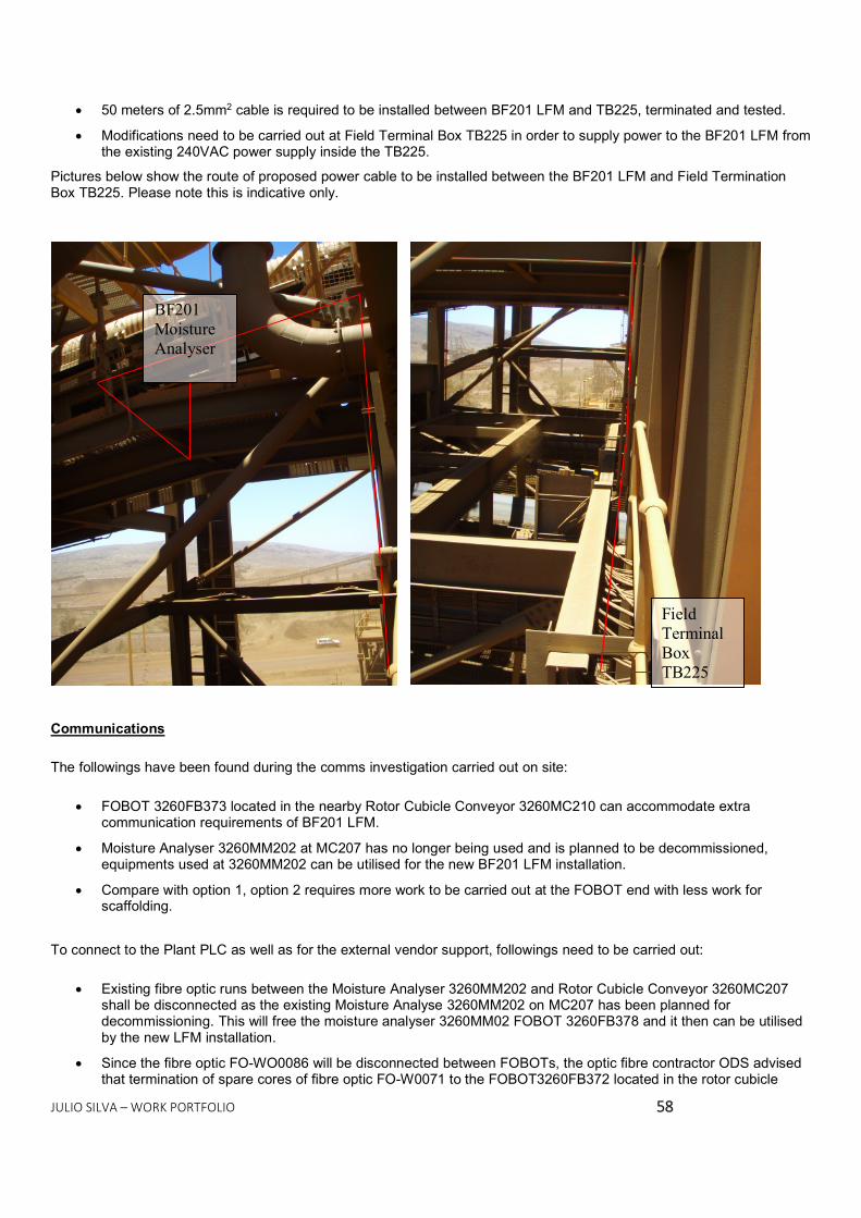
JULIO SILVA – WORK PORTFOLIO 5588
50 meters of 2.5mm2 cable is required to be installed between BF201 LFM and TB225, terminated and tested. Modifications need to be carried out at Field Terminal Box TB225 in order to supply power to the BF201 LFM from
the existing 240VAC power supply inside the TB225. Pictures below show the route of proposed power cable to be installed between the BF201 LFM and Field Termination Box TB225. Please note this is indicative only.
Communications The followings have been found during the comms investigation carried out on site:
FOBOT 3260FB373 located in the nearby Rotor Cubicle Conveyor 3260MC210 can accommodate extra communication requirements of BF201 LFM.
Moisture Analyser 3260MM202 at MC207 has no longer being used and is planned to be decommissioned, equipments used at 3260MM202 can be utilised for the new BF201 LFM installation.
Compare with option 1, option 2 requires more work to be carried out at the FOBOT end with less work for scaffolding. To connect to the Plant PLC as well as for the external vendor support, followings need to be carried out:
Existing fibre optic runs between the Moisture Analyser 3260MM202 and Rotor Cubicle Conveyor 3260MC207 shall be disconnected as the existing Moisture Analyse 3260MM202 on MC207 has been planned for decommissioning. This will free the moisture analyser 3260MM02 FOBOT 3260FB378 and it then can be utilised by the new LFM installation.
Since the fibre optic FO-WO0086 will be disconnected between FOBOTs, the optic fibre contractor ODS advised that termination of spare cores of fibre optic FO-W0071 to the FOBOT3260FB372 located in the rotor cubicle
BF201 Moisture Analyser
Field Terminal Box TB225

JULIO SILVA – WORK PORTFOLIO 5599
conveyor 3260MC207 needs to be carried out accordingly to the BHPB standards. A new 12 core single mode fibre optic shall be installed between BF201 LFM FOBOT and Rotor Cubicle Conveyor 3260MC210 FOBOT. New fibre optic shall be terminated at Stockyard 1 substation 3260SUB206 FOBOT 3160FB274 via in line splice
though rotor cubicle conveyor 3260MC210 FOBOT 3260FB373. Modifications shall be carried out at following FOBOTs:
o Rotor cubicle conveyor 3260MC07 FOBOT 3260FB375 o Stockyard 1 substation 3260SUB206 FOBOT 3160FB274 o Stockyard 1 substation 3160TXS272 media converter o Stockyard 1 substation 3160SUB206 FOBOT 3160FB272 o Stockyard 1 substation 3160SUB206 FOBOT 3160FB273 o Rotor cubicle conveyor 3260MC207 FOBOT 3260FB372
Label modifications shall be carried out for all modified FOBOTs and fibre optics. Pictures below show changes required for the existing fibre optic network to accommodate the new BF201 LFM for option 2 (indicative only):
Figure 6.1 - Existing Fibre Optic Network
Figure 2 - Proposed Fibre Optic Network for option 2
Detailed changes to the existing fibre optic network can be found on the attached red-line drawings 860-E-00015, 860-E-00142, 860-E-00119, 860-E-00118, 860-E-00094, 860-E-00046, 860-E-00116 and communication cable schedule 869-E-00070.
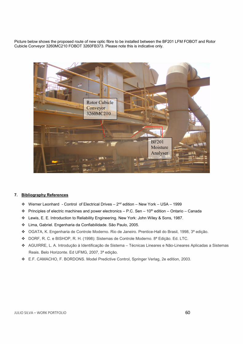
JULIO SILVA – WORK PORTFOLIO 6600
Picture below shows the proposed route of new optic fibre to be installed between the BF201 LFM FOBOT and Rotor Cubicle Conveyor 3260MC210 FOBOT 3260FB373. Please note this is indicative only.
7. Bibliography References
Werner Leonhard - Control of Electrical Drives – 2nd edition – New York – USA – 1999 Principles of electric machines and power electronics – P.C. Sen – 10th edition – Ontario – Canada Lewis, E. E. Introduction to Reliability Engineering. New York: John Wiley & Sons, 1987. Lima, Gabriel. Engenharia da Confiabilidade. São Paulo, 2005. OGATA, K. Engenharia de Controle Moderno. Rio de Janeiro. Prentice-Hall do Brasil, 1998, 3ª edição. DORF, R. C. e BISHOP, R. H. (1998): Sistemas de Controle Moderno. 8ª Edição. Ed. LTC. AGUIRRE, L. A. Introdução à Identificação de Sistema – Técnicas Lineares e Não-Lineares Aplicadas a Sistemas
Reais. Belo Horizonte. Ed UFMG, 2007, 3ª edição. E.F. CAMACHO, F. BORDONS. Model Predictive Control, Springer Verlag, 2e edition, 2003.
Rotor Cubicle Conveyor 3260MC210
BF201 Moisture Analyser