juggler user manual 1 - seitecno.com juggler.pdf · 5 juggler user manual 1.0 1.1 information...
TRANSCRIPT

Juggler
Seite 1
User Manual
USO
RES
TRIT
O

© 2013 Riedel Communications GmbH & Co KG. All rights reserved.
Under the copyright laws, this manual may not be copied, in whole or in part, without the written consent of Riedel. Every effort has been made to
ensure that the information in this manual is accurate. Riedel is not responsible for printing or clerical errors. All trademarks are the property of their
respective owners.
Seite 2
USO
RES
TRIT
O
Juggler User Manual 1.0
Seite 3
CONTENT
4Preface 1
............................................................................................................................................................................................................................................ 5Information1.1
............................................................................................................................................................................................................................................ 8Version1.2
9About Juggler 2
10Software 3
............................................................................................................................................................................................................................................ 12General Settings3.1
............................................................................................................................................................................................................................................ 14Audio Stream3.2
............................................................................................................................................................................................................................................ 17Artist3.3
............................................................................................................................................................................................................................................ 18Miscellaneous3.4
............................................................................................................................................................................................................................................ 19Disk Logging3.5
20Hardware 4
............................................................................................................................................................................................................................................ 20Frame4.1
............................................................................................................................................................................................................................................ 23Status LEDs4.2
24Connection to a Damm System 5
............................................................................................................................................................................................................................................ 24Setup of the System5.1
.............................................................................................................................................................................................................................. 24System assembly5.1.1
.............................................................................................................................................................................................................................. 25Remote Desktop Connection5.1.2
............................................................................................................................................................................................................................................ 26Damm - Juggler Configuration5.2
.............................................................................................................................................................................................................................. 26Software & Network M anagement5.2.1
.............................................................................................................................................................................................................................. 27M CC & M NC transfer5.2.2
.............................................................................................................................................................................................................................. 28Enable Application Gateway5.2.3
.............................................................................................................................................................................................................................. 29Damm Organization5.2.4
.............................................................................................................................................................................................................................. 30Damm Profile5.2.5
.............................................................................................................................................................................................................................. 31Create Subscr iber List5.2.6
.............................................................................................................................................................................................................................. 32Create and transfer Application SSI5.2.7
.............................................................................................................................................................................................................................. 34Configure Audio Stream5.2.8
............................................................................................................................................................................................................................................ 35Artist - Juggler Configuration5.3
.............................................................................................................................................................................................................................. 35Configure of M adi 4-Wire5.3.1
.............................................................................................................................................................................................................................. 36Create Conferences5.3.2
.............................................................................................................................................................................................................................. 38Set Conferences5.3.3
.............................................................................................................................................................................................................................. 40Configure Send Str ing5.3.4
.............................................................................................................................................................................................................................. 41Connect Artist with Juggler5.3.5
............................................................................................................................................................................................................................................ 41Program Radio5.4
............................................................................................................................................................................................................................................ 42Troubleshooting5.5
43Appendix 6
............................................................................................................................................................................................................................................ 43Technical Specifications6.1
............................................................................................................................................................................................................................................ 44Glossary6.2
............................................................................................................................................................................................................................................ 45Pin Outs6.3
............................................................................................................................................................................................................................................ 46Service6.4USO
RES
TRIT
O
4
Juggler User Manual 1.0
1 Preface
Thank you for choosing a Riedel product.
This Operating Manual provides detailed information about the Juggler system, especially operating and
installing instructions, pin outs, mechanical and electrical data. This Operating Manual is dedicated to
engineers and field technicians.
NOTICE
This manual, as well as the software and any examples contained herein are provided “as is” and are subject
to change without notice. The content of this manual is for informational purpose only and should not be
construed as a commitment by Riedel Communications GmbH & Co. KG or its suppliers. Riedel
Communications GmbH & Co. KG gives no warranty of any kind with regard to this manual or the software,
including, but not limited to, the implied warranties of merchantability and fitness for a particular purpose.
Riedel Communications GmbH & Co. KG shall not be liable for any errors, inaccuracies or for incidental or
consequential damages in connection with the furnishing, performance or use of this manual, the software
or the examples herein. Riedel Communications GmbH & Co. KG reserves all patent, proprietary design, title
and intellectual property rights contained herein, including, but not limited to, any images, text,
photographs incorporated into the manual or software.
Juggler User Manual 1.0
© November 2013 Copyright Riedel Communications GmbH & Co. KG.
All rights reserved. Reproduction, adaptation, or translation of this manual in whole or in part is prohibited
without prior written permission of Riedel GmbH, except as allowed under the copyright laws.
All other trademarks are the property of their respective owner.
USO
RES
TRIT
O
5
Juggler User Manual 1.0
1.1 Information
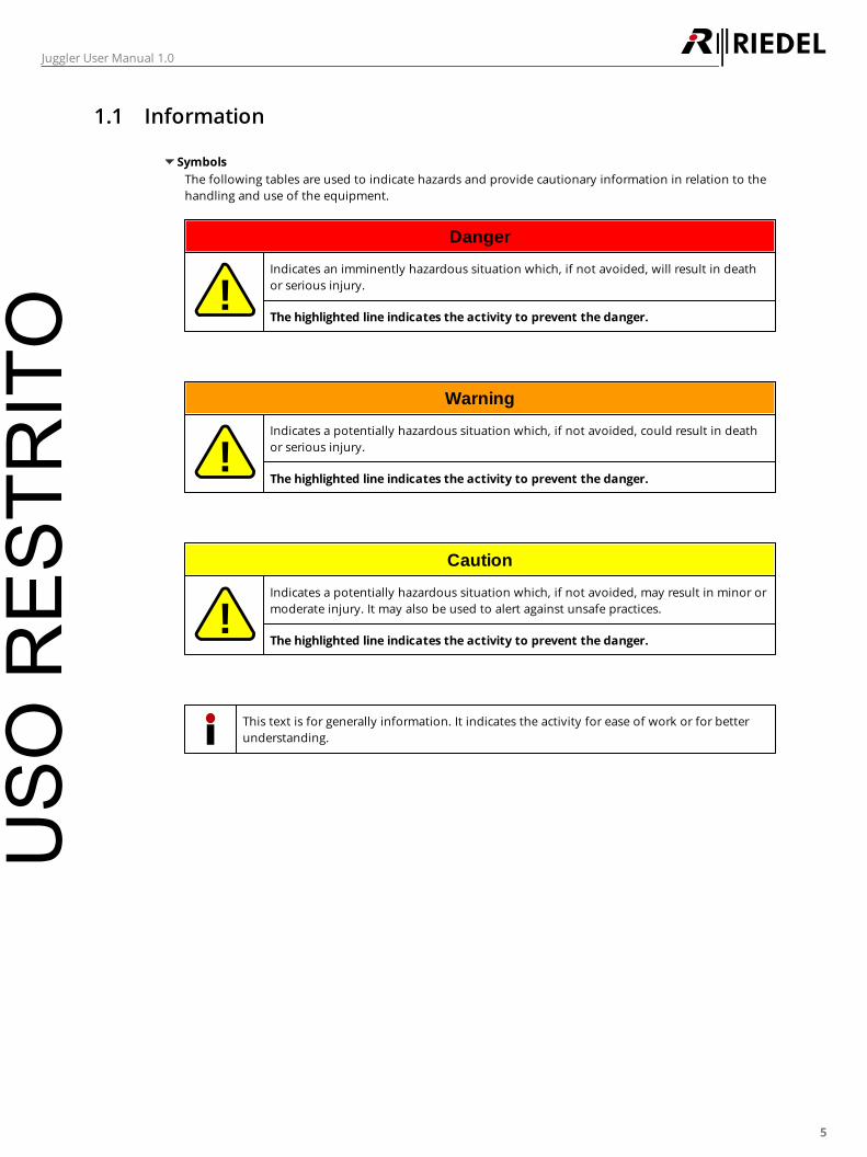
Symbols
The following tables are used to indicate hazards and provide cautionary information in relation to the
handling and use of the equipment.
Danger
!Indicates an imminently hazardous situation which, if not avoided, will result in death
or serious injury.
The highlighted line indicates the activity to prevent the danger.
Warning
!Indicates a potentially hazardous situation which, if not avoided, could result in death
or serious injury.
The highlighted line indicates the activity to prevent the danger.
Caution
!Indicates a potentially hazardous situation which, if not avoided, may result in minor or
moderate injury. It may also be used to alert against unsafe practices.
The highlighted line indicates the activity to prevent the danger.
This text is for generally information. It indicates the activity for ease of work or for better
understanding.
USO
RES
TRIT
O
6
Juggler User Manual 1.0
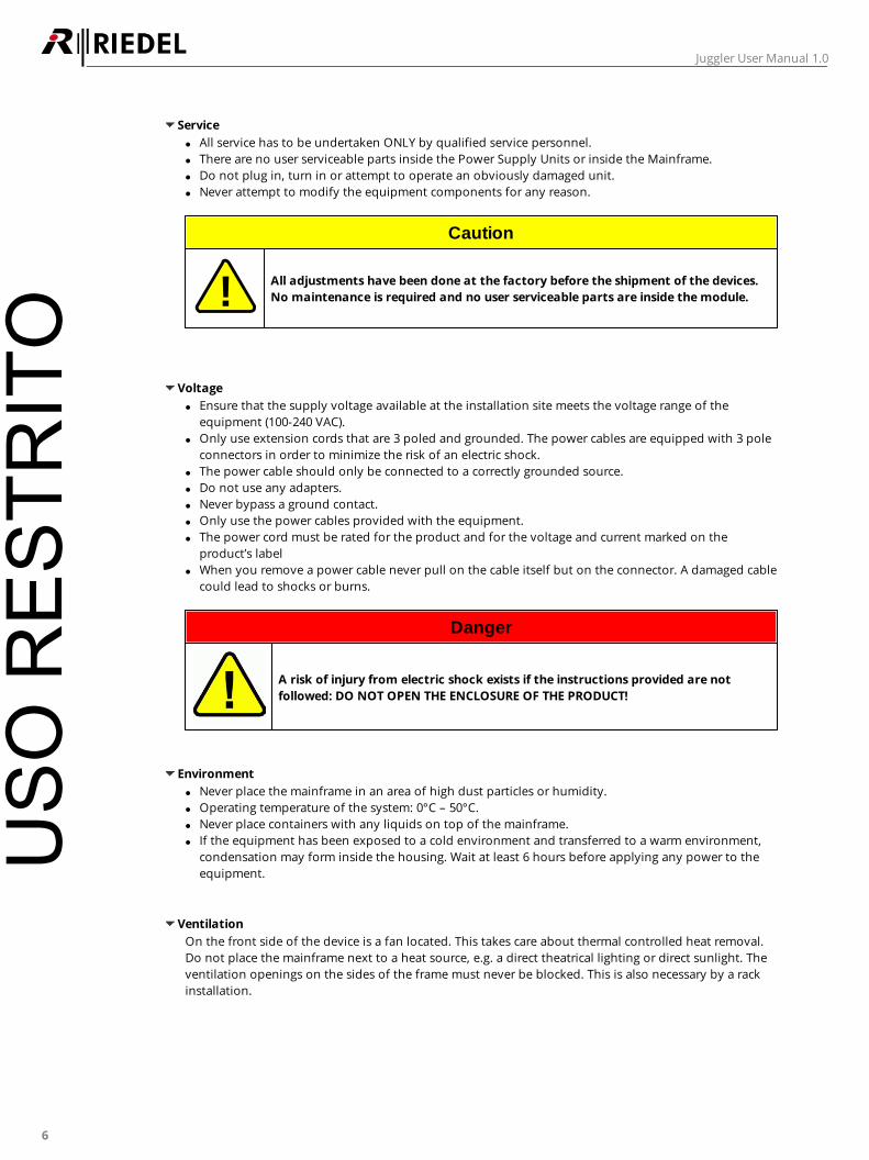
Service
All service has to be undertaken ONLY by qualified service personnel.
There are no user serviceable parts inside the Power Supply Units or inside the Mainframe.
Do not plug in, turn in or attempt to operate an obviously damaged unit.
Never attempt to modify the equipment components for any reason.
Caution
! All adjustments have been done at the factory before the shipment of the devices.
No maintenance is required and no user serviceable parts are inside the module.
Voltage
Ensure that the supply voltage available at the installation site meets the voltage range of the
equipment (100-240 VAC).
Only use extension cords that are 3 poled and grounded. The power cables are equipped with 3 pole
connectors in order to minimize the risk of an electric shock.
The power cable should only be connected to a correctly grounded source.
Do not use any adapters.
Never bypass a ground contact.
Only use the power cables provided with the equipment.
The power cord must be rated for the product and for the voltage and current marked on the
product’s label
When you remove a power cable never pull on the cable itself but on the connector. A damaged cable
could lead to shocks or burns.
Danger
A risk of injury from electric shock exists if the instructions provided are not
followed: DO NOT OPEN THE ENCLOSURE OF THE PRODUCT!
Environment
Never place the mainframe in an area of high dust particles or humidity.
Operating temperature of the system: 0°C – 50°C.
Never place containers with any liquids on top of the mainframe.
If the equipment has been exposed to a cold environment and transferred to a warm environment,
condensation may form inside the housing. Wait at least 6 hours before applying any power to the
equipment.
Ventilation
On the front side of the device is a fan located. This takes care about thermal controlled heat removal.
Do not place the mainframe next to a heat source, e.g. a direct theatrical lighting or direct sunlight. The
ventilation openings on the sides of the frame must never be blocked. This is also necessary by a rack
installation.
USO
RES
TRIT
O
7
Juggler User Manual 1.0
Installation
Please familiarize yourself with the device and its operation and read this Operating Manual carefully.
Juggler are designed for 19” rack mount installation. Please make sure that common installation basics
are taken care of:
Do not install any devices in a location subjected to excessive heat such as direct theatrical lighting or
direct sunlight
Make sure sufficient airflow is granted
Use devices in environmental temperature range between
0°C and 50°C or 32°F and 122°F
Do not place any items on top of the devices
Protect devices from mechanical and electrical shock
Protect devices from mechanical vibration
Protect devices from moisture and liquidity impact of any kind
Protect devices from dust and dirt
Unpacking
Save all the packing materials. They will prove valuable should it become necessary to transport or
ship this product.
Please inspect the RockNet device carefully for any signs of damage incurred during transportation.
If the product shows any signs of damage, please notify the transportation company without delay.
Do not connect a damaged device to AC power outlets.
Only the consignee may institute a claim against the carrier for damage during transportation.
If necessary, contact your supplier or as a last resort, your local Riedel distributor, dealer or agent,
who will fully cooperate under such circumstances.
Disposal
Disposal of old Electrical & Electric Equipment
(Applicable throughout the European Union and other European countries with separate collection
programs)
This symbol, found on your product or on its packaging, indicates that this product
should not be treated as household waste when you wish to dispose of it. Instead, it
should be handed over to an applicable collection point for the recycling of electrical
and electronic equipment. By ensuring this product is disposed of correctly, you will
help prevent potential negative consequences to the environment and human health,
which could otherwise be caused by inappropriate disposal of this product. The
recycling of materials will help to conserve natural resources. For more detailed
information about the recycling of this product please contact your local city office.
CE Declaration of Conformity
The Artist devices conform to the EU guideline
EMC 2004 / 108 / EC,
Low - Voltage 2006 / 95 / EC
as attested by the CE mark.
USO
RES
TRIT
O

8
Juggler User Manual 1.0
1.2 Version
This manual refers to Juggler Version 1.25
The Juggler version 1.25 is only applicable with the Damm software version 7.52.
Version Check
The software version is attached behind the filename of the Juggler application.
After starting the application the software version is displayed in the headline.
By right-clicking the headline a popup-menu appears and the window "About Juggler..." can be opened.
Figure 1: Software versionUSO
RES
TRIT
O
9
Juggler User Manual 1.0
2 About Juggler
Besides wireless intercom systems, wireless communications at events are
usually based on professional mobile radios or digital trunked radios.
While analog radios are easily integrated with the wired intercom system via
the Riedel RiFace, Riedel now provides JUGGLER, a compact TETRA digital
trunked radio network solution for Artist Digital Matrix Intercoms, which
provides seamless integration of wired intercom and professional digital radio
applications.
While digital TETRA radios have been providing many advantages such as
optimal frequency usage, highest transmission quality for audio and data and
maximum security against eavesdropping, TETRA remained unsuitable for
many applications because the installations were large and expensive. Riedel
JUGGLER provides for the first time a cost-effective and compact solution,
which makes it ideal not only for fixed installations but also mobile
applications and OB trucks.
The new Riedel JUGGLER TETRA solution seamlessly integrates the TETRA radio
network into the wired intercom matrix, providing intelligent
integration between TETRA radio groups and Riedel Artist intercom ports. The
system allows calls from any port/group/conference of the Artist system to up
to 64 individual TETRA radio groups and vice versa. JUGGELR works with any
TETRA-standard compliant subscriber station.
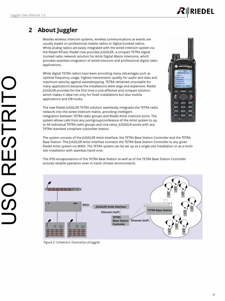
The system consists of the JUGGLER Artist Interface, the TETRA Base Station Controller and the TETRA
Base Station. The JUGGLER Artist Interface connects the TETRA Base Station Controller to any given
Riedel Artist system via MADI. The TETRA system can be set up as a single-site installation or as a multi-
site installation with seamless hand-over.
The IP65 encapsulations of the TETRA Base Station as well as of the TETRA Base Station Controller
ensures reliable operation even in harsh climatic environments.
Figure 2: Schem atic illustration of Juggler
USO
RES
TRIT
O
10
Juggler User Manual 1.0
3 Software
The configuration of the juggler can be done in application with the same name.
After starting the software, a window with 5 different tabs will appear. The tabs will be described in the
following chapters.
The main menu of the Juggler software contains two entries:
File --> Exit Closing the Juggler application
View --> Logging Show/hide the logging window
Please take care to open following network ports, if you are using a firewall on the Juggler:
TCP/IP: 8192, 8194, 42380
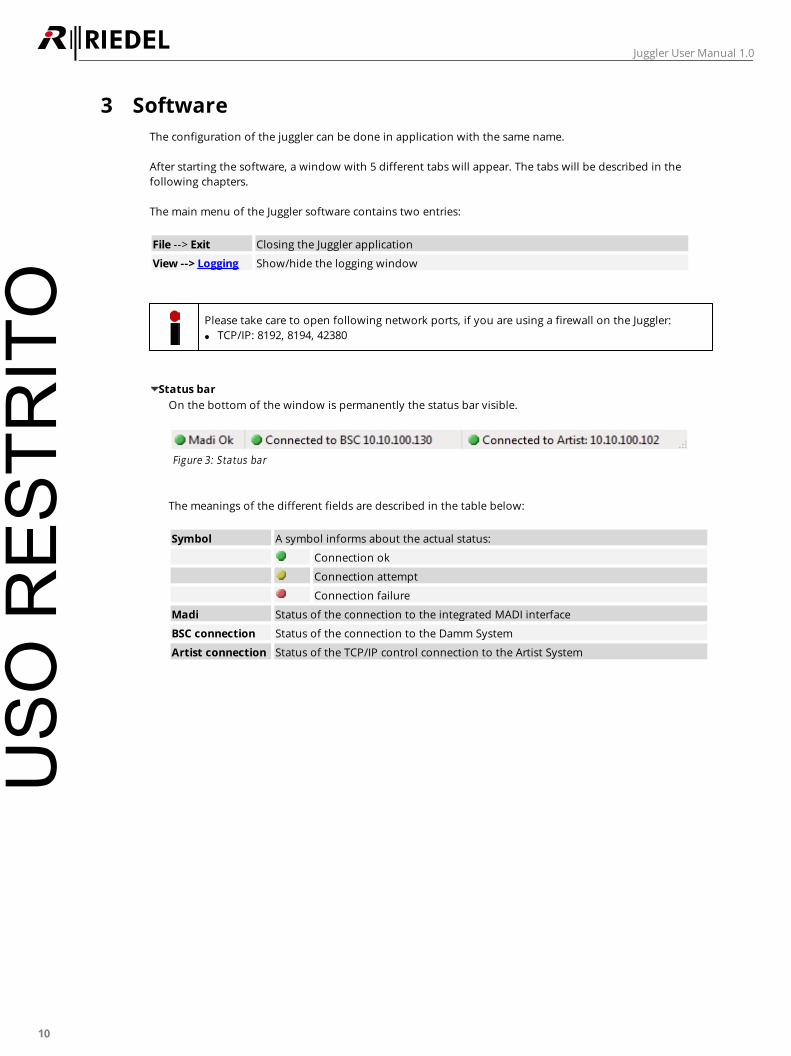
Status bar
On the bottom of the window is permanently the status bar visible.
Figure 3: Status bar
The meanings of the different fields are described in the table below:
Symbol A symbol informs about the actual status:
Connection ok
Connection attempt
Connection failure
Madi Status of the connection to the integrated MADI interface
BSC connection Status of the connection to the Damm System
Artist connection Status of the TCP/IP control connection to the Artist System
USO
RES
TRIT
O
11
Juggler User Manual 1.0
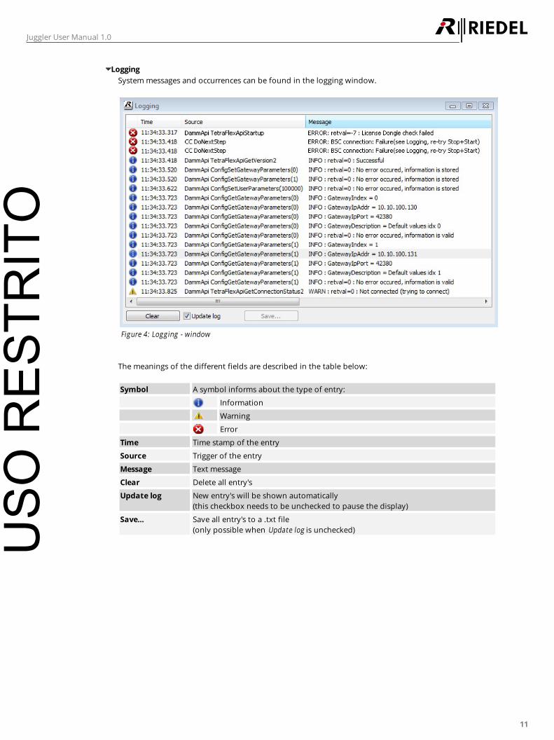
Logging
System messages and occurrences can be found in the logging window.
Figure 4: Logging - window
The meanings of the different fields are described in the table below:
Symbol A symbol informs about the type of entry:
Information
Warning
Error
Time Time stamp of the entry
Source Trigger of the entry
Message Text message
Clear Delete all entry's
Update log New entry's will be shown automatically
(this checkbox needs to be unchecked to pause the display)
Save... Save all entry's to a .txt file
(only possible when Update log is unchecked)USO
RES
TRIT
O
12
Juggler User Manual 1.0
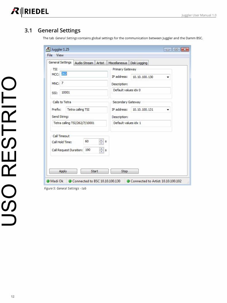
3.1 General Settings
The tab General Settings contains global settings for the communication between Juggler and the Damm BSC.
Figure 5: General Settings - tab
USO
RES
TRIT
O

13
Juggler User Manual 1.0
The meanings of the different fields are described in the table below:
TSI MCC Definition of the Mobile Country Code
(see configuration of the DAMM BSC).
MNC Definition of the Mobile Network Code
(see configuration of the DAMM BSC).
SSI Definition of the Short Subscriber Identity
(see configuration of the DAMM BSC).
Primary Gateway IP address Input of the IP address of the primary gateway
(previous inputs can be selected in the drop-down list).
Description Short description of the primary gateway.
Calls to Tetra Prefix Input of the prefix, which will be sent before each call
(command trigger of the Juggler. The Artist need to send this
call command).
Send String Display of the complete command, which is necessary to trigger
the communication between Artist and BSC via Juggler. This
string can be copied from this field and pasted in the respective
Artist configuration (combination of:
Prefix+"/"+MMC+"/"+MNC+"/"+SSI).
Secondary
Gateway
IP address Input of the IP address of the secondary gateway
(previous inputs can be selected in the drop-down list).
Description Short description of the secondary gateway.
Call Timeout Call Hold Time Input of the time, how long a call will be hold.
Call Request
Duration
Input of the time, how long a call will be requested.
Apply Confirm/activate the entries.
Start Starting the connection to the BSC.
Stop Stopping the connection to the BSC.
USO
RES
TRIT
O
14
Juggler User Manual 1.0
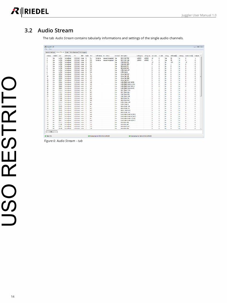
3.2 Audio Stream
The tab Audio Stream contains tabularly informations and settings of the single audio channels.
Figure 6: Audio Stream - tab
USO
RES
TRIT
O
15
Juggler User Manual 1.0
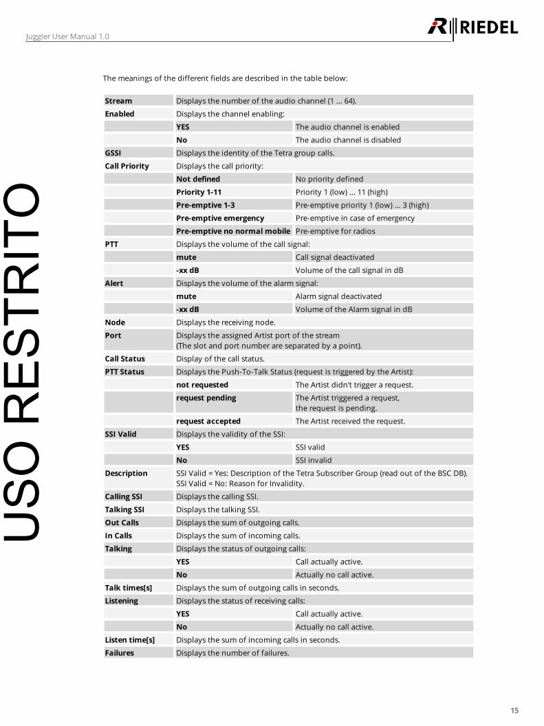
The meanings of the different fields are described in the table below:
Stream Displays the number of the audio channel (1 ... 64).
Enabled Displays the channel enabling:
YES The audio channel is enabled
No The audio channel is disabled
GSSI Displays the identity of the Tetra group calls.
Call Priority Displays the call priority:
Not defined No priority defined
Priority 1-11 Priority 1 (low) ... 11 (high)
Pre-emptive 1-3 Pre-emptive priority 1 (low) ... 3 (high)
Pre-emptive emergency Pre-emptive in case of emergency
Pre-emptive no normal mobile Pre-emptive for radios
PTT Displays the volume of the call signal:
mute Call signal deactivated
-xx dB Volume of the call signal in dB
Alert Displays the volume of the alarm signal:
mute Alarm signal deactivated
-xx dB Volume of the Alarm signal in dB
Node Displays the receiving node.
Port Displays the assigned Artist port of the stream
(The slot and port number are separated by a point).
Call Status Display of the call status.
PTT Status Displays the Push-To-Talk Status (request is triggered by the Artist):
not requested The Artist didn't trigger a request.
request pending The Artist triggered a request,
the request is pending.
request accepted The Artist received the request.
SSI Valid Displays the validity of the SSI:
YES SSI valid
No SSI invalid
Description SSI Valid = Yes: Description of the Tetra Subscriber Group (read out of the BSC DB).
SSI Valid = No: Reason for Invalidity.
Calling SSI Displays the calling SSI.
Talking SSI Displays the talking SSI.
Out Calls Displays the sum of outgoing calls.
In Calls Displays the sum of incoming calls.
Talking Displays the status of outgoing calls:
YES Call actually active.
No Actually no call active.
Talk times[s] Displays the sum of outgoing calls in seconds.
Listening Displays the status of receiving calls:
YES Call actually active.
No Actually no call active.
Listen time[s] Displays the sum of incoming calls in seconds.
Failures Displays the number of failures.
USO
RES
TRIT
O

16
Juggler User Manual 1.0
The selected stream can be edited by double clicking or by clicking the EDIT button.
Figure 7: Edit Audio Stream Param eters - window
The meanings of the different fields are described in the table below:
Stream Displays the number of the audio channel (1 ... 64) to be edit.
Enabled Enabling of the audio channel:
checked Activate the audio channel.
unchecked Deactivate the audio channel.
Group Call SSI Definition of the identity of the Tetra group calls.
Call Priority Selection of the call priority:
Not defined No priority selected.
Priority 1-11 Priority 1 (low) ... 11 (high).
Pre-emptive 1-3 Pre-emptive priority 1 (low) ... 3 (high).
Pre-emptive emergency Pre-emptive in case of emergency.
Pre-emptive no normal mobile Pre-emptive for radios.
PTT Setting the volume of the call signal:
mute Call signal deactivated
-xx dB Volume of the call signal in dB
Alert Setting the volume of the alarm signal:
mute Alarm signal deactivated
-xx dB Volume of the alarm signal in dB
Node Entering the receiving Artist node of this stream.
Slot Entering the receiving slot number (of the Artist node) of this stream.
Port Entering the receiving port
number (of the Artist slot) of this
steam.
USO
RES
TRIT
O
17
Juggler User Manual 1.0
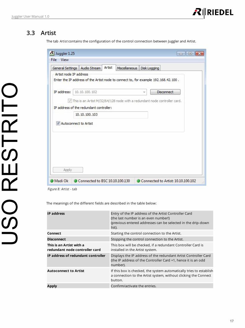
3.3 Artist
The tab Artist contains the configuration of the control connection between Juggler and Artist.
Figure 8: Artist - tab
The meanings of the different fields are described in the table below:
IP address Entry of the IP address of the Artist Controller Card
(the last number is an even number!)
(previous entered addresses can be selected in the drip-down
list).
Connect Starting the control connection to the Artist.
Disconnect Stopping the control connection to the Artist.
This is an Artist with a
redundant node controller card
This box will be checked, if a redundant Controller Card is
installed in the Artist system.
IP address of redundant controller Displays the IP address of the redundant Artist Controller Card
(the IP address of the Controller Card +1, hence it is an odd
number).
Autoconnect to Artist If this box is checked, the system automatically tries to establish
a connection to the Artist system, without clicking the Connect
button.
Apply Confirm/activate the entries.
USO
RES
TRIT
O
18
Juggler User Manual 1.0
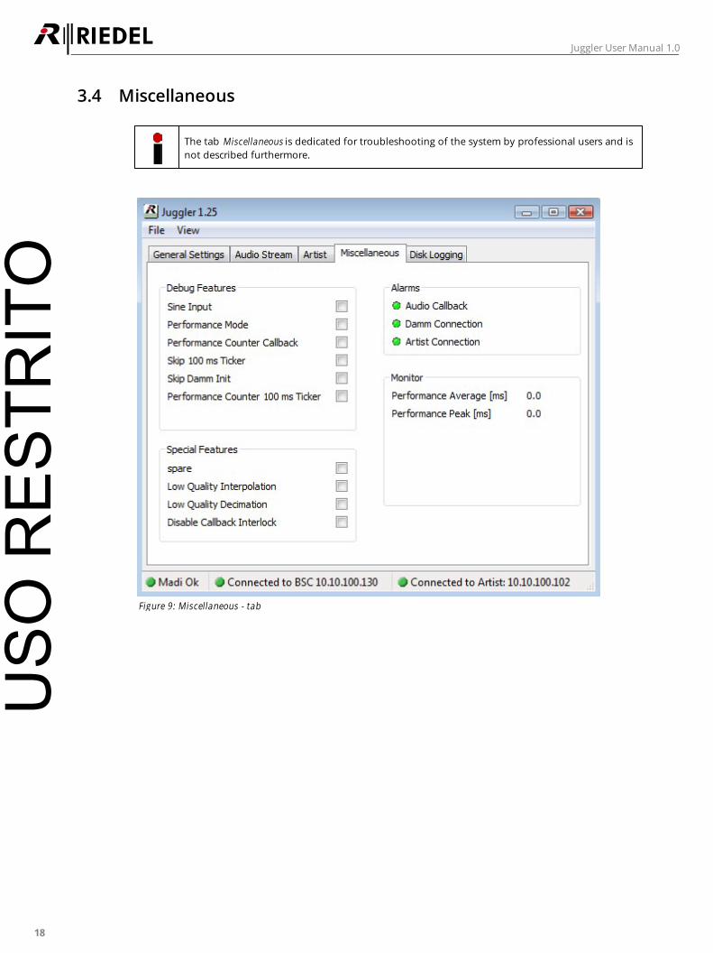
3.4 Miscellaneous
The tab Miscellaneous is dedicated for troubleshooting of the system by professional users and is
not described furthermore.
Figure 9: Miscellaneous - tab
USO
RES
TRIT
O
19
Juggler User Manual 1.0
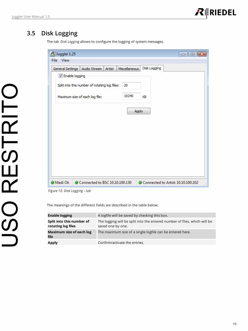
3.5 Disk Logging
The tab Disk Logging allows to configure the logging of system messages.
Figure 10: Disk Logging - tab
The meanings of the different fields are described in the table below:
Enable logging A logfile will be saved by checking this box.
Split into this number of
rotating log files
The logging will be split into the entered number of files, which will be
saved one by one.
Maximum size of each log
file
The maximum size of a single logfile can be entered here.
Apply Confirm/activate the entries.USO
RES
TRIT
O
20
Juggler User Manual 1.0
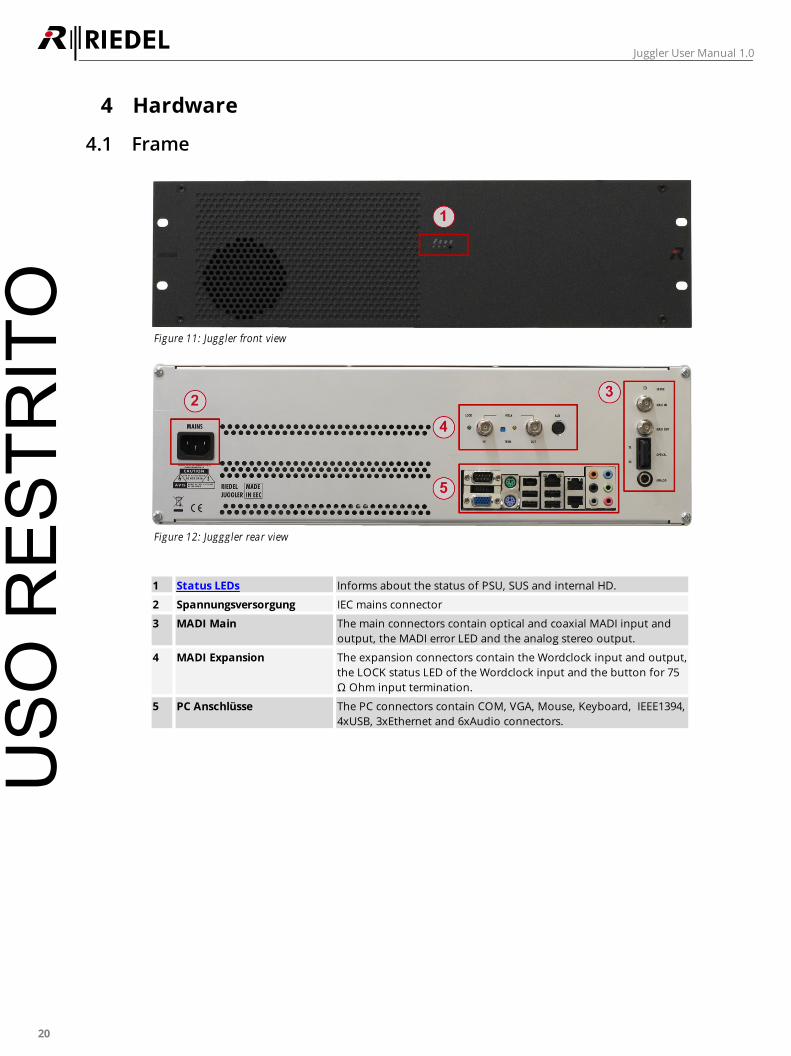
4 Hardware
4.1 Frame
Figure 11: Juggler front view
Figure 12: Jugggler rear view
1 Status LEDs Informs about the status of PSU, SUS and internal HD.
2 Spannungsversorgung IEC mains connector
3 MADI Main The main connectors contain optical and coaxial MADI input and
output, the MADI error LED and the analog stereo output.
4 MADI Expansion The expansion connectors contain the Wordclock input and output,
the LOCK status LED of the Wordclock input and the button for 75
Ω Ohm input termination.
5 PC Anschlüsse The PC connectors contain COM, VGA, Mouse, Keyboard, IEEE1394,
4xUSB, 3xEthernet and 6xAudio connectors.
USO
RES
TRIT
O
21
Juggler User Manual 1.0
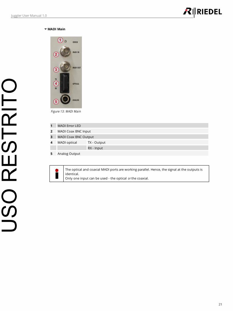
MADI Main
Figure 13: MADI Main
1 MADI Error LED
2 MADI Coax BNC Input
3 MADI Coax BNC Output
4 MADI optical TX - Output
RX - Input
5 Analog Output
The optical and coaxial MADI ports are working parallel. Hence, the signal at the outputs is
identical.
Only one input can be used - the optical or the coaxial.
USO
RES
TRIT
O
22
Juggler User Manual 1.0
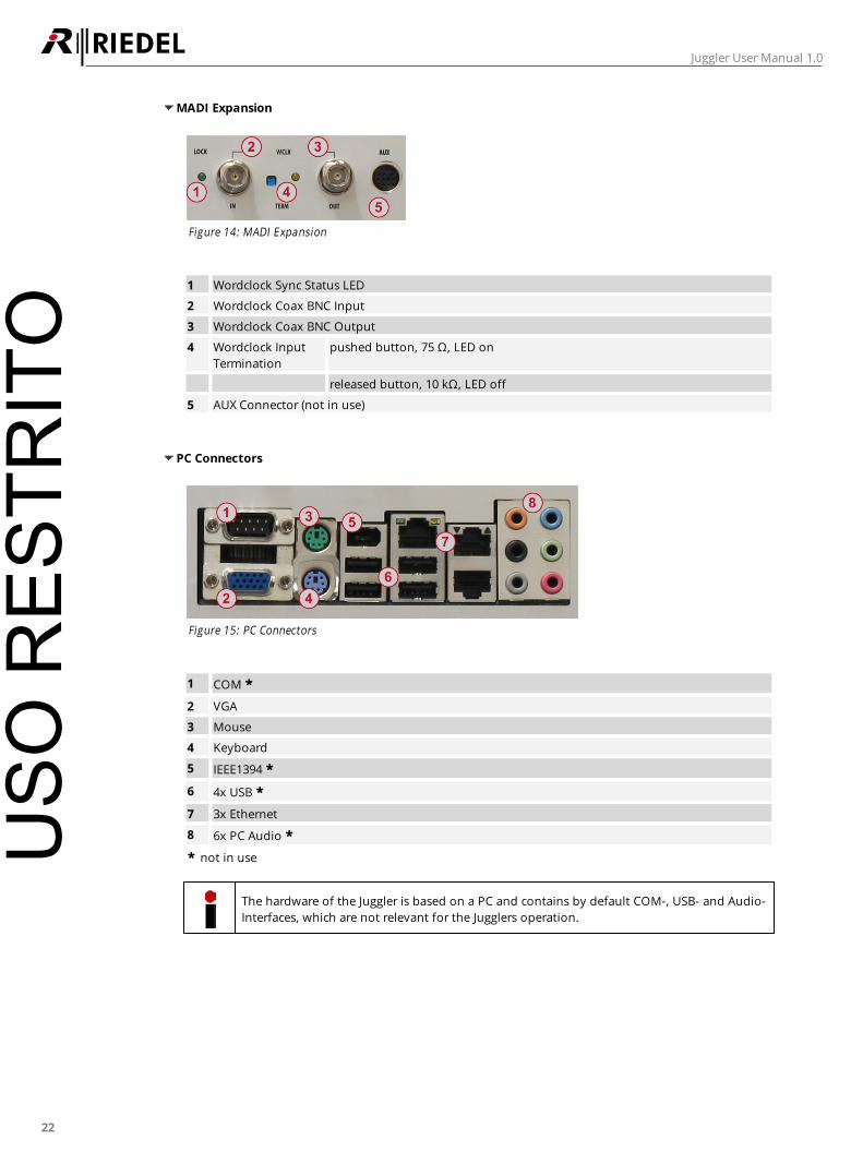
MADI Expansion
Figure 14: MADI Expansion
1 Wordclock Sync Status LED
2 Wordclock Coax BNC Input
3 Wordclock Coax BNC Output
4 Wordclock Input
Termination
pushed button, 75 Ω, LED on
released button, 10 kΩ, LED off
5 AUX Connector (not in use)
PC Connectors
Figure 15: PC Connectors
1 COM *
2 VGA
3 Mouse
4 Keyboard
5 IEEE1394 *
6 4x USB *
7 3x Ethernet
8 6x PC Audio *
* not in use
The hardware of the Juggler is based on a PC and contains by default COM-, USB- and Audio-
Interfaces, which are not relevant for the Jugglers operation.
USO
RES
TRIT
O
23
Juggler User Manual 1.0
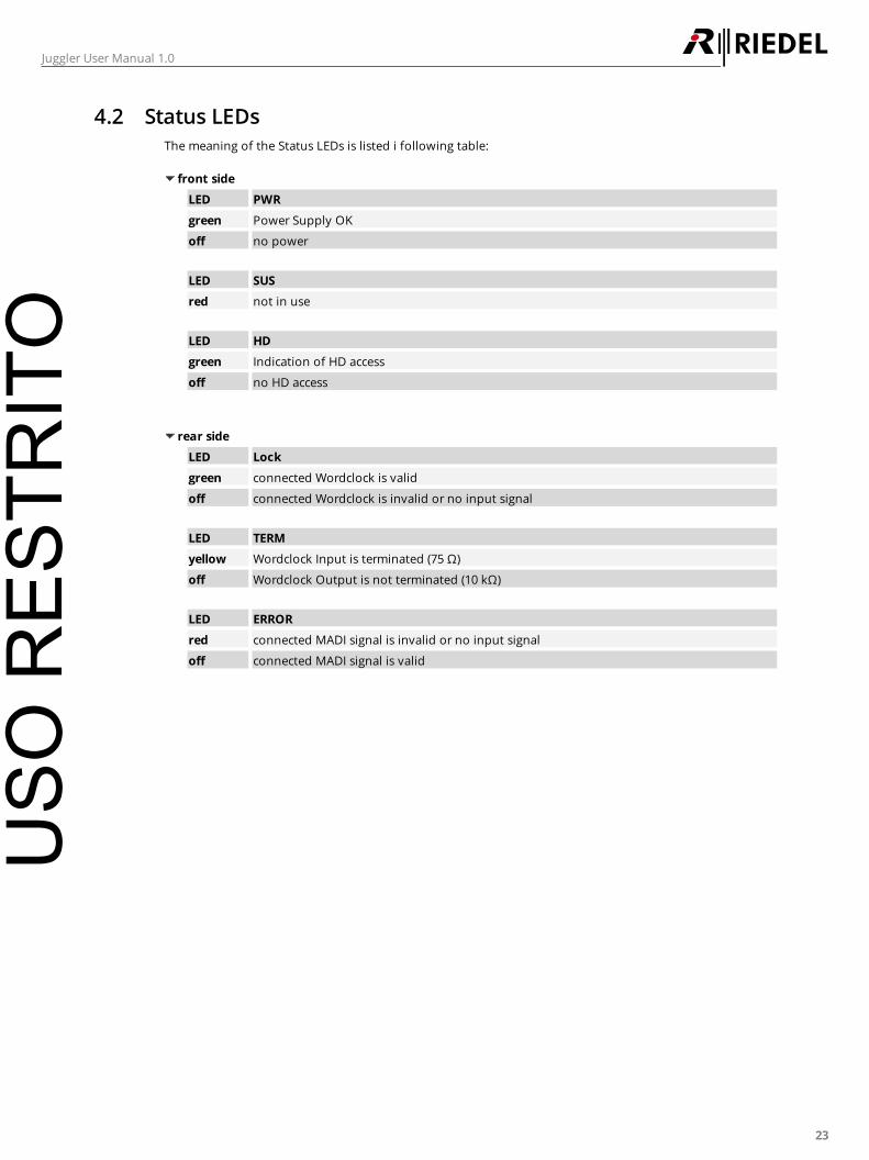
4.2 Status LEDs
The meaning of the Status LEDs is listed i following table:
front side
LED PWR
green Power Supply OK
off no power
LED SUS
red not in use
LED HD
green Indication of HD access
off no HD access
rear side
LED Lock
green connected Wordclock is valid
off connected Wordclock is invalid or no input signal
LED TERM
yellow Wordclock Input is terminated (75 Ω)
off Wordclock Output is not terminated (10 kΩ)
LED ERROR
red connected MADI signal is invalid or no input signal
off connected MADI signal is valid
USO
RES
TRIT
O

24
Juggler User Manual 1.0
5 Connection to a Damm System
This chapter describes the necessary steps to establish a connection between a Damm system and an Artist
system via the Juggler.
5.1 Setup of the System
5.1.1 System assembly
First of all the required equipment needs to be collected
Following items are required:
1 x Artist with MADI – Client Card and Key-Panel
1 x Juggler PC
1 x Tetra Damm System
1 x Network Switch
1 x Configuration PC
1 x API Dongle for the Juggler
Coax- and/or Cat5-Cable and/or Optical Fiber
Now its time to connect the configuration PC, the Artist system, the Damm system and both network
interfaces of the Juggler with the network switch.
Further connect the MADI interfaces of the Artist node and the Juggler via coax or optical fiber. Take care that
the RX-Artist is connected to the MADI Out of the Juggler and the TX-Artist to the MADI In of the Juggler.
Then the Artist key-panel is configured in the Artist system and connected to the respective port.
Take care that the configuration PC is configured to the same IP network as the other devices.
These may be different for all devices.
This example shows 8 radio groups configured independently to 8 conferences on one key-panel. The WAN
network interface of the Damm system is set to 10.10.100.130 for instance to another LAN as the Artist
network interface with 192.168.42.110. The Juggler contains two network interfaces. Both ones needs to be
connected to the network switch to be able to work in both LANs without an additional router. For this the
TCP/IPv4 settings need to contain the respective IP ranges. In this example the Juggler has the IP
192.168.42.200 on the internal network interface and the IP 10.10.100.100 on the external one. In case the
Juggler has only one network interface, the second IP range need to be entered in the advanced properties of
the TCP/IPv4 settings.
USO
RES
TRIT
O
25
Juggler User Manual 1.0
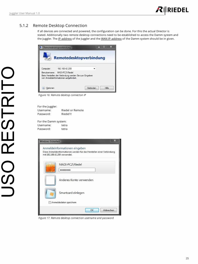
5.1.2 Remote Desktop Connection
If all devices are connected and powered, the configuration can be done. For this the actual Director is
stated. Additionally two remote desktop connections need to be established to access the Damm system and
the Juggler. The IP-address of the Juggler and the WAN IP-address of the Damm system should be in given.
Figure 16: Rem ote desktop connecton IP
For the Juggler:
Username: Riedel or Remote
Password: Riedel1!
For the Damm system:
Username: tetra
Password: tetra
Figure 17: Rem ote desktop connection usernam e and password
USO
RES
TRIT
O
26
Juggler User Manual 1.0
5.2 Damm - Juggler Configuration
After all devices are accessible, proceed with the configuration.
An API-Dongle for the communication between Juggler and Damm system is required.
The API-Dongle is plugged into an unused USB port in the Juggler.
The Damm system should be already set up.
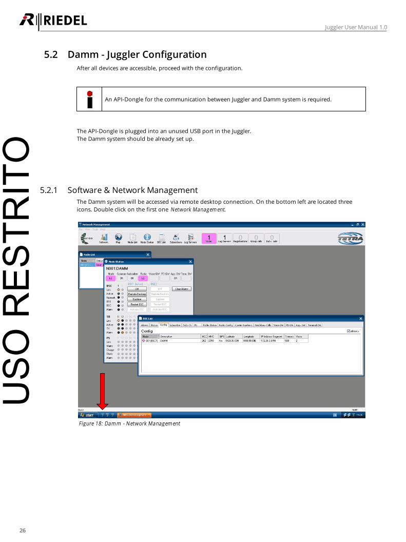
5.2.1 Software & Network Management
The Damm system will be accessed via remote desktop connection. On the bottom left are located three
icons. Double click on the first one Network Managem ent.
Figure 18: Dam m - Network Managem ent
USO
RES
TRIT
O
27
Juggler User Manual 1.0
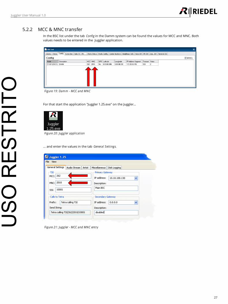
5.2.2 MCC & MNC transfer
In the BSC list under the tab Config in the Damm system can be found the values for MCC and MNC. Both
values needs to be entered in the Juggler application.
Figure 19: Dam m - MCC and MNC
For that start the application "Juggler 1.25.exe" on the Juggler...
Figure 20: Juggler application
... and enter the values in the tab General Settings.
Figure 21: Juggler - MCC and MNC entryUSO
RES
TRIT
O

28
Juggler User Manual 1.0
5.2.3 Enable Application Gateway
To enable the Juggler to operate with the Damm system, set in the BSC list on the tab Application Gateway the
field Config to the value "Yes".
Figure 22: Dam m - Application Gateway in BSC List
USO
RES
TRIT
O
29
Juggler User Manual 1.0
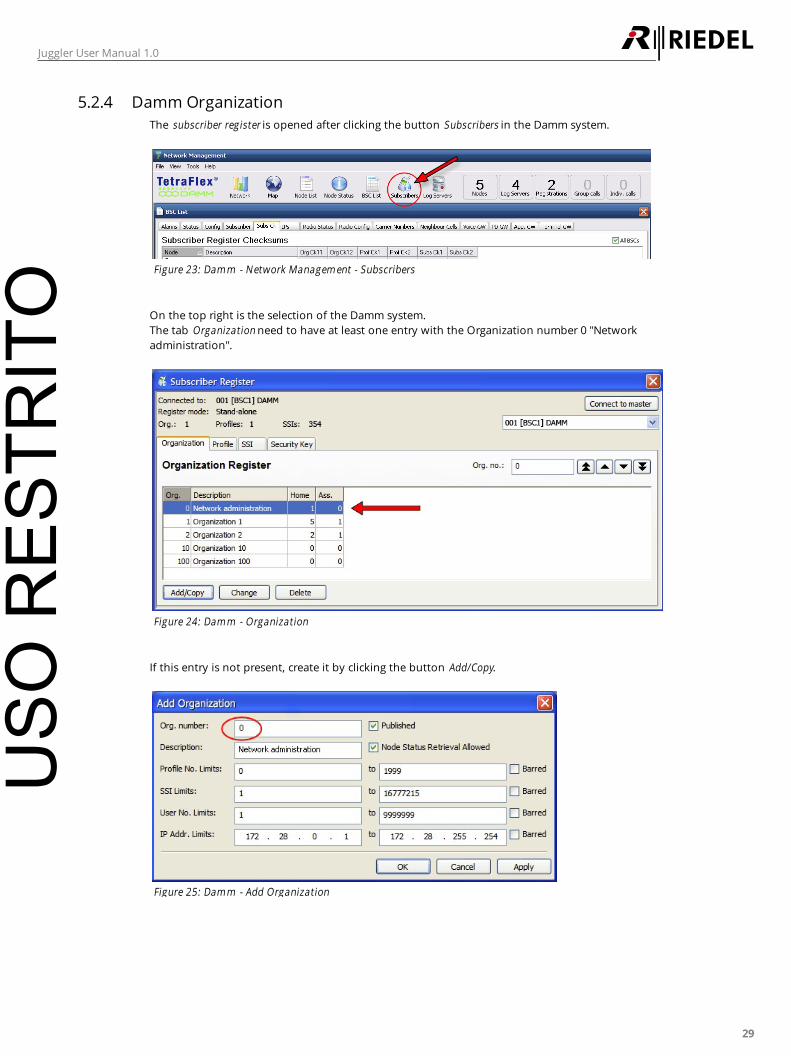
5.2.4 Damm Organization
The subscriber register is opened after clicking the button Subscribers in the Damm system.
Figure 23: Dam m - Network Managem ent - Subscribers
On the top right is the selection of the Damm system.
The tab Organization need to have at least one entry with the Organization number 0 "Network
administration".
Figure 24: Dam m - Organization
If this entry is not present, create it by clicking the button Add/Copy.
Figure 25: Dam m - Add Organization
USO
RES
TRIT
O
30
Juggler User Manual 1.0
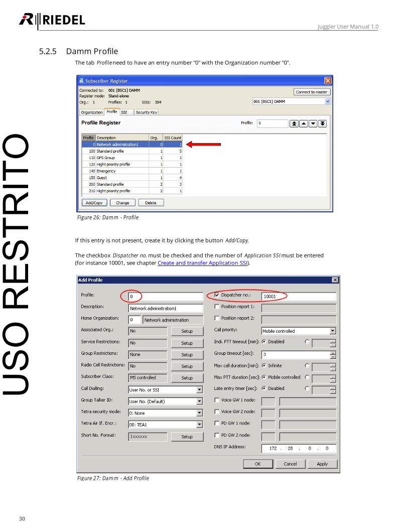
5.2.5 Damm Profile
The tab Profile need to have an entry number "0" with the Organization number "0".
Figure 26: Dam m - Profile
If this entry is not present, create it by clicking the button Add/Copy.
The checkbox Dispatcher no. must be checked and the number of Application SSI must be entered
(for instance 10001, see chapter Create and transfer Application SSI).
Figure 27: Dam m - Add Profile
USO
RES
TRIT
O

31
Juggler User Manual 1.0
5.2.6 Create Subscriber List
In the tab SSI unused Groups are selected and the SSI number for the configuration of the Juggler is set. It is
helpful to label the Groups meaningful (for instance Radio 1...8).
Figure 28: Dam m - Groups in the tab Subscriber
By clicking the button Add/Copy, new Groups can be created.
Existing Groups can be modified by clicking the button Change.
Figure 29: Dam m - Change SSI Group
USO
RES
TRIT
O
32
Juggler User Manual 1.0
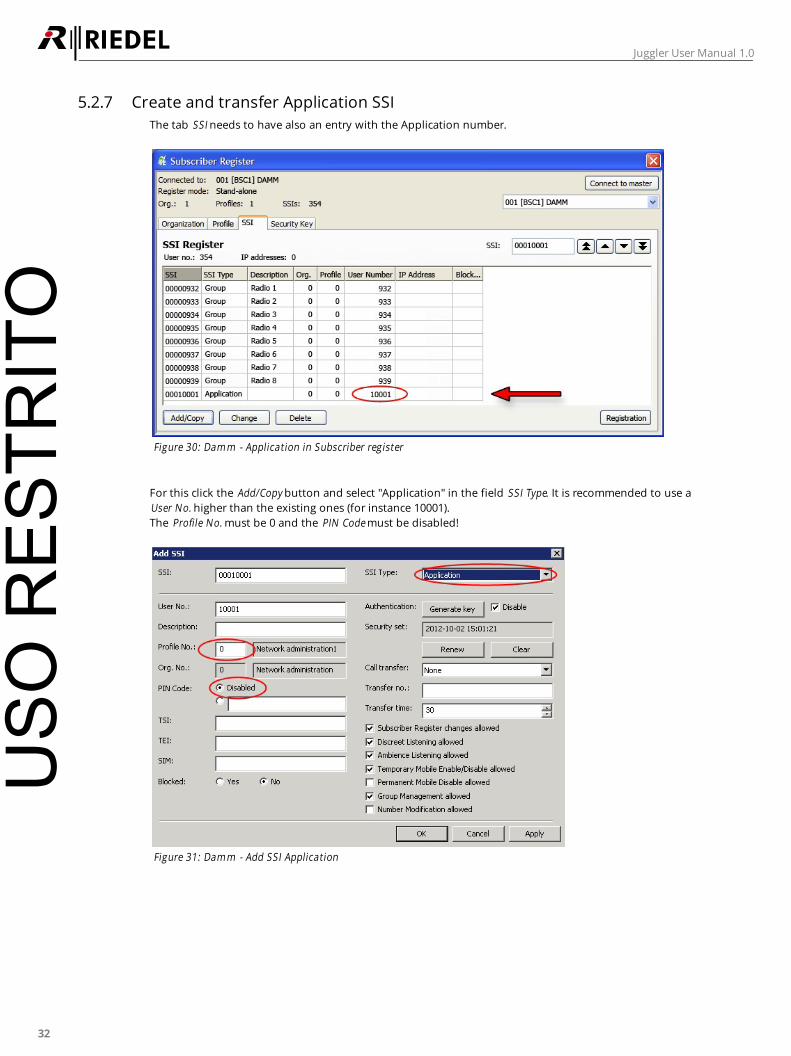
5.2.7 Create and transfer Application SSI
The tab SSI needs to have also an entry with the Application number.
Figure 30: Dam m - Application in Subscriber register
For this click the Add/Copy button and select "Application" in the field SSI Type. It is recommended to use a
User No. higher than the existing ones (for instance 10001).
The Profile No. must be 0 and the PIN Code must be disabled!
Figure 31: Dam m - Add SSI Application
USO
RES
TRIT
O

33
Juggler User Manual 1.0
The User No. needs to be set also in the Juggler application in tab General Settings.
Figure 32: Juggler - Application User No. in tab General Settings
USO
RES
TRIT
O

34
Juggler User Manual 1.0
5.2.8 Configure Audio Stream
In the tab Audio Stream in the Juggler application the streams will be assigned to the respective Damm-SSIs
and Artist node and ports. To fetch the slot and port numbers of the Artist system it is helpful to pre-
configure it first (see chapter Artist - Juggler Configuration).
Figure 33: Juggler - tab Audio Stream
By double-clicking a row, a window opens to change the contents.
The SSI in the Juggler need to match the SSI of the Damm system.
Figure 34: Juggler - Edit Audio Stream
The selected SSIs need to be enabled. PTT Feedback and Alert may be adjusted as required.
USO
RES
TRIT
O
35
Juggler User Manual 1.0
5.3 Artist - Juggler Configuration
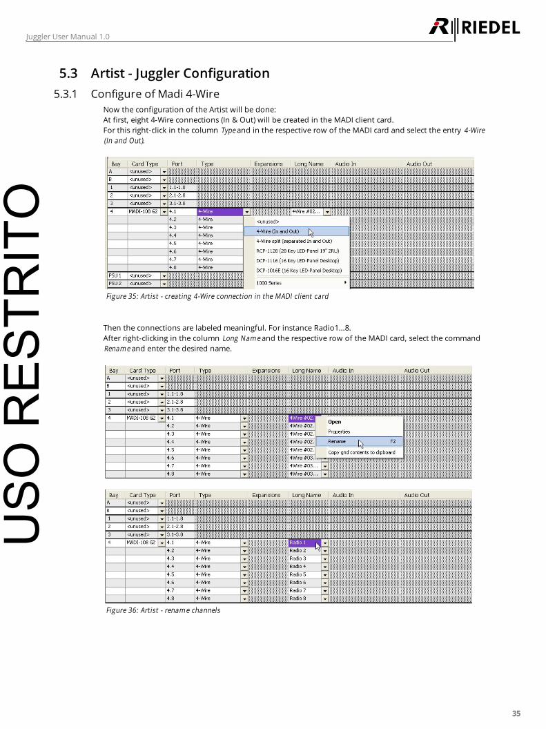
5.3.1 Configure of Madi 4-Wire
Now the configuration of the Artist will be done:
At first, eight 4-Wire connections (In & Out) will be created in the MADI client card.
For this right-click in the column Type and in the respective row of the MADI card and select the entry 4-Wire
(In and Out).
Figure 35: Artist - creating 4-Wire connection in the MADI client card
Then the connections are labeled meaningful. For instance Radio1...8.
After right-clicking in the column Long Nam e and the respective row of the MADI card, select the command
Renam e and enter the desired name.
Figure 36: Artist - renam e channels
USO
RES
TRIT
O
36
Juggler User Manual 1.0
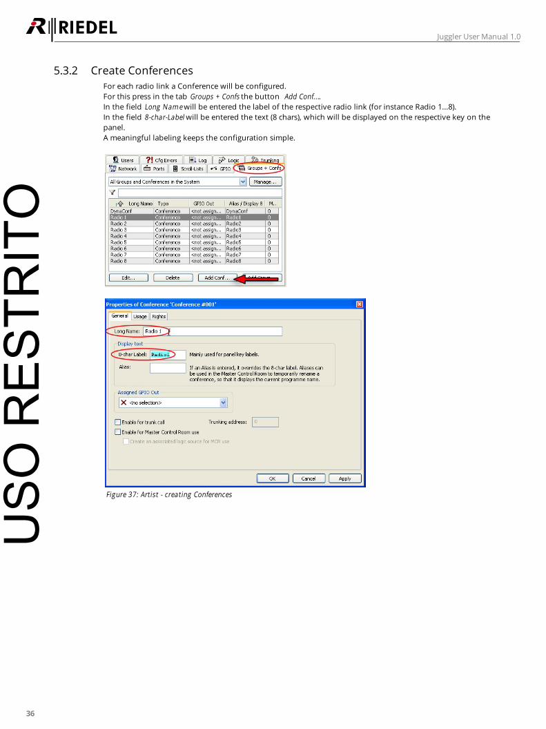
5.3.2 Create Conferences
For each radio link a Conference will be configured.
For this press in the tab Groups + Confs the button Add Conf....
In the field Long Nam e will be entered the label of the respective radio link (for instance Radio 1...8).
In the field 8-char-Label will be entered the text (8 chars), which will be displayed on the respective key on the
panel.
A meaningful labeling keeps the configuration simple.
Figure 37: Artist - creating Conferences
USO
RES
TRIT
O

37
Juggler User Manual 1.0
One MADI card can be configured to 8 sequential channels within one MADI signal. The selection of the
channels is done in the properties of the MADI card, which can be opened by right-clicking on the respective
MADI card in the column Card Type, followed by selecting the command Properties.
Figure 38: Artist - MADI Properties
In the field MADI Channels can be selected the block of required channels.
Figure 39: Artist - MADI Channel selection
USO
RES
TRIT
O

38
Juggler User Manual 1.0
5.3.3 Set Conferences
Each Conference will be assigned to the VOX function of the respective MADI 4-Wire interface and to an
unused key on the panel.
For this right-click in the respective MADI 4-Wire and select the entry Open.
Figure 40: Artist - assigning the Conference
After right-clicking on "Virtual Functions - VOX", select the command "Add Function - Call to Conference".
Figure 41: Artist - VOX Function - Call to Conference
Select in the following window in the field Destination the respective name of the radio link.
Figure 42: Artist - Select Destination
USO
RES
TRIT
O
39
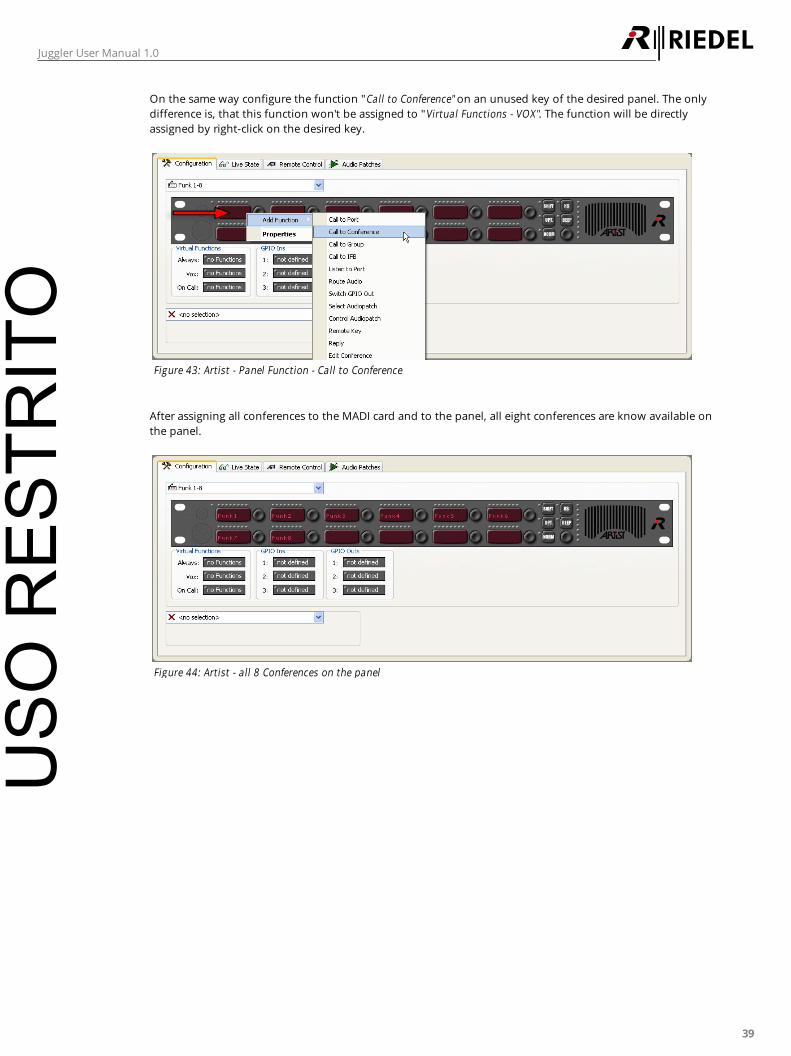
Juggler User Manual 1.0
On the same way configure the function "Call to Conference" on an unused key of the desired panel. The only
difference is, that this function won't be assigned to "Virtual Functions - VOX". The function will be directly
assigned by right-click on the desired key.
Figure 43: Artist - Panel Function - Call to Conference
After assigning all conferences to the MADI card and to the panel, all eight conferences are know available on
the panel.
Figure 44: Artist - all 8 Conferences on the panel
USO
RES
TRIT
O
40
Juggler User Manual 1.0
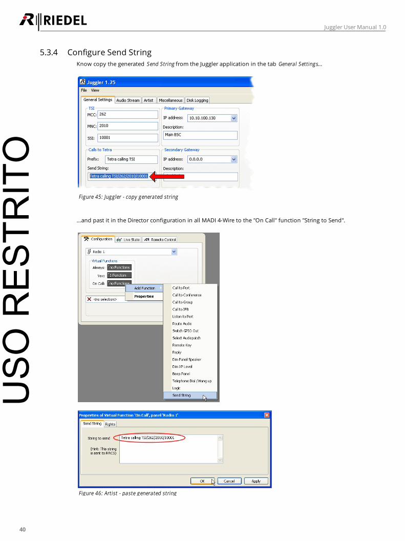
5.3.4 Configure Send String
Know copy the generated Send String from the Juggler application in the tab General Settings...
Figure 45: Juggler - copy generated string
...and past it in the Director configuration in all MADI 4-Wire to the "On Call" function "String to Send".
Figure 46: Artist - paste generated string
USO
RES
TRIT
O
41
Juggler User Manual 1.0
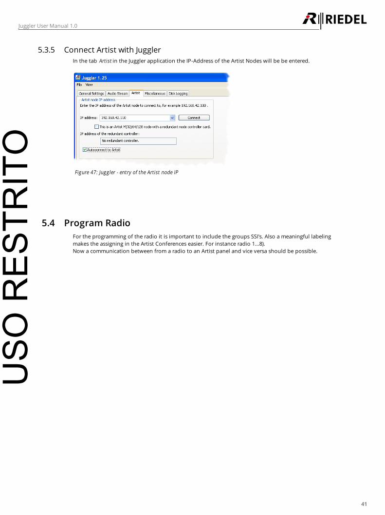
5.3.5 Connect Artist with Juggler
In the tab Artist in the Juggler application the IP-Address of the Artist Nodes will be be entered.
Figure 47: Juggler - entry of the Artist node IP
5.4 Program Radio
For the programming of the radio it is important to include the groups SSI's. Also a meaningful labeling
makes the assigning in the Artist Conferences easier. For instance radio 1...8).
Now a communication between from a radio to an Artist panel and vice versa should be possible.
USO
RES
TRIT
O
42
Juggler User Manual 1.0
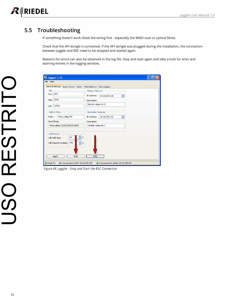
5.5 Troubleshooting
If something doesn't work check the wiring first - especially the MADI coax or optical fibres.
Check that the API dongle is connected. If the API dongle was plugged during the installation, the connection
between Juggler and BSC need to be stopped and started again.
Reasons for errors can also be observed in the log file. Stop and start again and take a look for error and
warning entries in the logging window.
Figure 48: Juggler - Stop and Start the BSC Connection
USO
RES
TRIT
O

43
Juggler User Manual 1.0
6 Appendix
6.1 Technical Specifications
MADI Input Channels 56 / 64
Sample rate 24 Bit, 48 kHz
Sync range 25 ... 54 kHz
Coax-BNC
Impedance 75 Ω
Optical FDDI Duplex SC
Input power -31 ... -14 dBm
Wavelength 1270 ... 1380 nm
Multimode 62.5/125 and 50/125 µm
MADI Output Channels 56 / 64
Sample rate 24 Bit, 48 kHz
Coax-BNC
Impedance 75 Ω
Output power max. 600 mVss
distance up to 100m
Optical FDDI Duplex SC
Output power -20 ... -14 dBm (62.5/125 µm)
-24 ... -14 dBm (50/125 µm)
Wavelength 1270 ... 1380 nm
distance up to 2 km
Multimode 62.5/125 and 50/125 µm
Wordclock Input BNC
Impedance 75 Ω / 10 kΩ switchable
Input power 1,0 ... 5,6 Vss
Sync range 28 ... 200 kHz
Wordclock Output BNC
Impedance 10 Ω
Output power max. 5 Vss
(4 Vss with 75 Ω termination)
Analog Output 6.3mm stereo jack socket
Impedance 75 Ω
Output power max. +13 dBu
Frequency response -0.5 dB, 5 ... 22 kHz
THD+N < -102 dB, < 0.0008 %
Operating Temperature -20 ... +55°C -4 ... +131°F
Input power 100 ... 240 VAC 47 ... 63 Hz
Power 120 VA
Dimensions (W × H × D) 483 × 133 (3HE) × 230 mm 19” × 5.25” (3RU) × 9.1”
Weight 2.4 kg 5.3 lbs
USO
RES
TRIT
O
44
Juggler User Manual 1.0
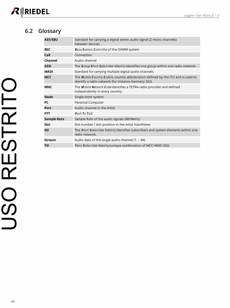
6.2 Glossary
AES/EBU Standard for carrying a digital stereo audio signal (2 mono channels)
between devices.
BSC Base Station Controller of the DAMM system
Call Connection
Channel Audio-channel
GSSI The G roup Short Subscriber Identity identifies one group within one radio network.
MADI Standard for carrying multiple digital audio channels.
MCC The Mobile Country Code is country abbreviation defined by the ITU and is used to
identify a radio network (for instance Germany 262).
MNC The Mobile Network Code identifies a TETRA-radio provider and defined
independently in every country.
Node Single Artist system
PC Personal Computer
Port Audio-channel in the Artist
PTT Push To Talk
Sample Rate Sample Rate of the audio signals (48/96kHz)
Slot Slot number / slot position in the Artist mainframe
SSI The Short Subscriber Identity identifies subscribers and system elements within one
radio network.
Stream Audio data of the single audio channel (1 ... 64)
TSI Tetra Subsrciber Identity (unique combination of MCC+MNC+SSI)
USO
RES
TRIT
O
45
Juggler User Manual 1.0
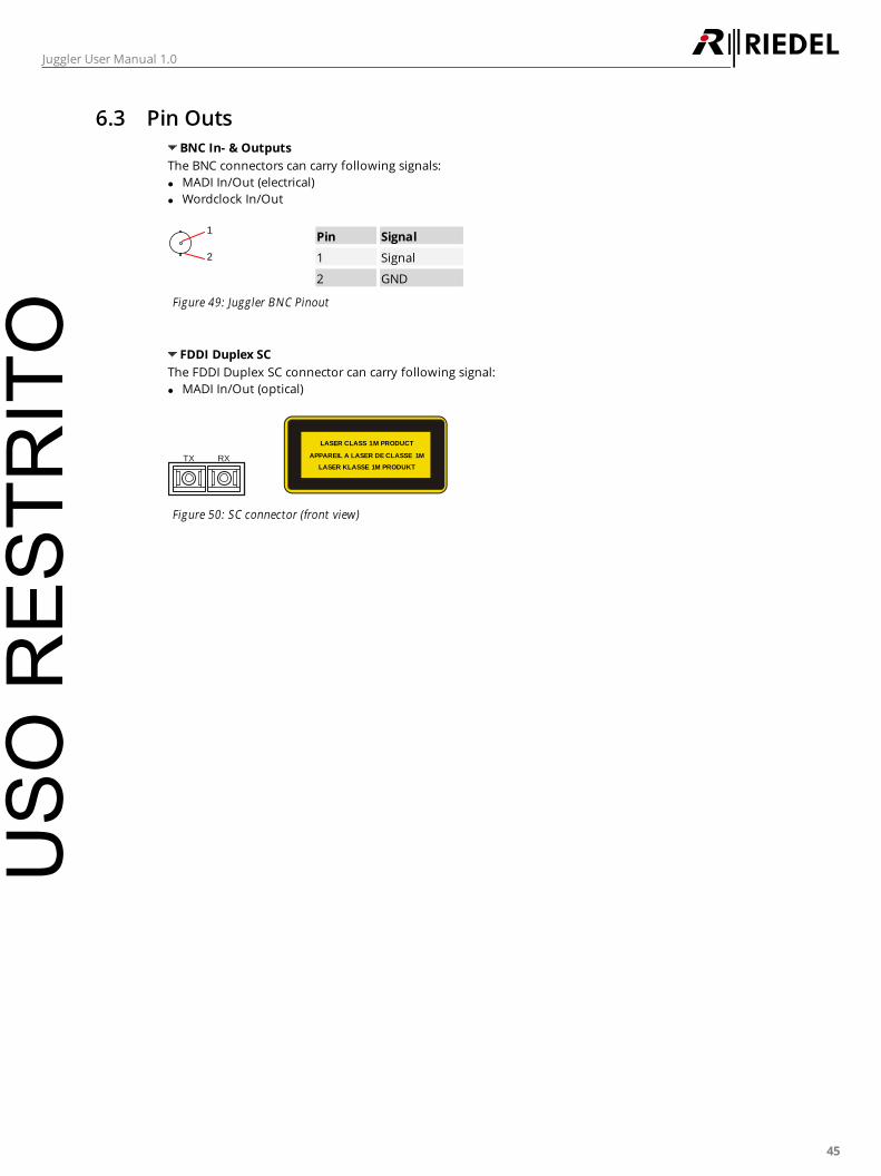
6.3 Pin Outs
BNC In- & Outputs
The BNC connectors can carry following signals:
MADI In/Out (electrical)
Wordclock In/Out
2
1Pin Signal
1 Signal
2 GND
Figure 49: Juggler BNC Pinout
FDDI Duplex SC
The FDDI Duplex SC connector can carry following signal:
MADI In/Out (optical)
TX RX
LASER CLASS 1M PRODUCT
APPAREIL A LASER DE CLASSE 1M
LASER KLASSE 1M PRODUKT
Figure 50: SC connector (front view)
USO
RES
TRIT
O
46
Juggler User Manual 1.0
6.4 Service
If you have any further questions, we offer comprehensive customer service options for this product
including:
Telephone Service
Email Service
Skype Service
Fax Service
Configuration Support
Trainings
Repair
Your primary point of contact for any service issues is your local dealer.
In addition, Riedel Customer Service in Wuppertal, Germany is also available to assist you.
Telephone: +49 (0) 202 292 9400
(Monday - Friday, 8am – 5pm, Central European Time)
Fax: +49 (0) 202 292 9419
Skype: riedel.communications.service
Or use the contact form on our website: www.riedel.net
For repairs, please contact your local dealer. Your dealer will be able to help process your repair as fast as
possible and/or arrange for the delivery of spare parts.
The address for repairs sent directly to Riedel Communications GmbH is:
Riedel Communications GmbH & Co. KG
- Repairs -
Uellendahler Str. 353
D-42109 Wuppertal
Germany
Please add a completed repair form to all your repairs.
The form can be found at the Riedel website -> download -> formsUSO
RES
TRIT
O

47
Juggler User Manual 1.0
Notes
USO
RES
TRIT
O

www.riedel.netRiedel Communications GmbH & Co. KG | Uellendahler Str. 353 | 42109 Wuppertal | Germany
USO
RES
TRIT
O