jt-60sa newsletter · delivered to the qst naka site on 8 august 2017. after the acceptance tests...
TRANSCRIPT
1 JT-60SA Newsletter No.93
Headline
TF coil delivery and assembly update
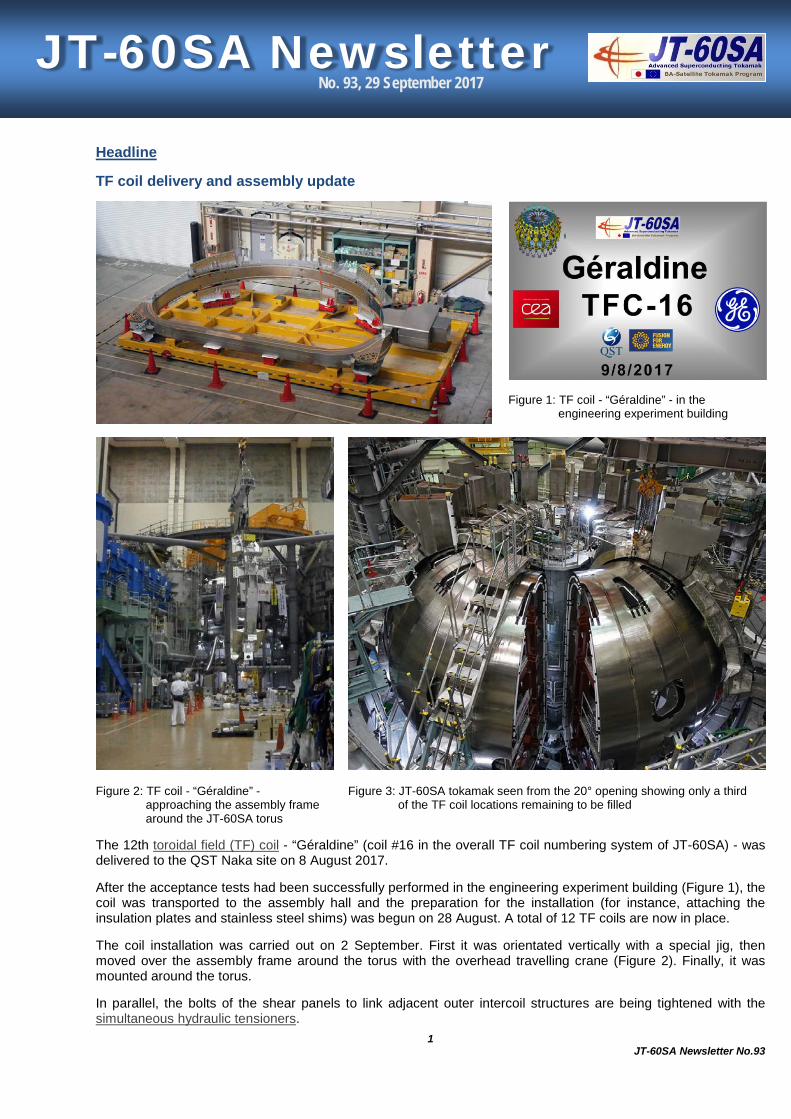
Figure 1: TF coil - “Géraldine” - in the engineering experiment building
Figure 2: TF coil - “Géraldine” - approaching the assembly frame around the JT-60SA torus
Figure 3: JT-60SA tokamak seen from the 20° opening showing only a third of the TF coil locations remaining to be filled
The 12th toroidal field (TF) coil - “Géraldine” (coil #16 in the overall TF coil numbering system of JT-60SA) - was delivered to the QST Naka site on 8 August 2017.
After the acceptance tests had been successfully performed in the engineering experiment building (Figure 1), the coil was transported to the assembly hall and the preparation for the installation (for instance, attaching the insulation plates and stainless steel shims) was begun on 28 August. A total of 12 TF coils are now in place.
The coil installation was carried out on 2 September. First it was orientated vertically with a special jig, then moved over the assembly frame around the torus with the overhead travelling crane (Figure 2). Finally, it was mounted around the torus.
In parallel, the bolts of the shear panels to link adjacent outer intercoil structures are being tightened with the simultaneous hydraulic tensioners.
JT-60SA Newsletter No. 93, 29 September 2017

2 JT-60SA Newsletter No.93
News
TF coil cold test optimisation at CEA Saclay
Figure 1: TF coil hanging on its support and surrounded by the thermal shroud in the cryostat at CEA Saclay
Because all the toroidal field (TF) coils of JT-60SA (18 production and 2 spare coils) have to be fully tested, there is always the risk that such testing will lie on the critical planning path of the device, where any delays may have a significant impact on the overall JT-60SA construction and commissioning schedule. It was therefore realised early on that optimisation of this testing would play a significant role in the success of JT-60SA.
When the cool-down of the first TF coil (TF coil #10 - “Annie” -) was begun on 1 February 2016 in the dedicated TF coil cold test facility (TFCTF) of CEA in Saclay, France (Figure 1), it took about 15 days for the coil to reach the operating temperature of about 4 K. Performing all the required functional tests, bringing the coil to the quench temperature, and warming the coil again to ambient temperature needed another 20 days. In total, the TFCTF cryostat was blocked for 56 days before it became available for the next test.
By September 2017, a total of 14 TF coils have been tested and the stay time of a single TF coil in the cryostat has decreased to below 27 days (Figure 2). This acceleration could be achieved by an improved, sophisticated cooling strategy and optimised execution of the different test procedures.
Figure 2: Duration the cryostat was occupied by a coil
Figure 3: Maximum resistance in Nano-Ohm of the single joints (orange) and total resistance of the tested TF coils (blue)

3 JT-60SA Newsletter No.93
Due to the heat input onto the coil, the coolant temperature in the winding pack (WP) increased typically by about 0.7 K. To have a more homogeneous temperature across the WP, it was decided to replace the temperature margin test at constant temperature with the quench test using a transient temperature profile. This approach was validated by F4E through a 3D thermal, hydraulic, and structural model. The quench temperatures measured were all between 7.44 K and 7.51 K, which were slightly higher than expected but in good agreement with the model.
Another important requirement to reduce ohmic heating losses is a very low joint resistance (below 2 nΩ) between the pancakes of the TF coil. To achieve such small resistances, it was required to measure very small voltages in the microvolt range in a very noisy environment. As can be seen in Figure 3, the measured joint resistances were typically around 1 nΩ, which were well within the specification.
The pressure drops of the TF coil WPs was also measured during the test, and compared with the predictions. On the basis of the individual flow coefficients (measured by CEA) of the samples of all conductors, the 12 parallel conductors in a WP were modelled, which reproduced the measured pressure drop within about 5 percent error range, indicating also that no degradation of the conductor occurred during winding.
With these improvements, the cold testing of all TF coils for JT-60SA will be completed by summer 2018.
News
Site acceptance test of CEA SCMPSs successfully completed
Figure 1: Group photo of the SCMPS team at the end of site acceptance tests
It has been a long ride.
When, in March 2013, the contract for the design, manufacturing, installation, and commissioning of the superconducting magnet power supplies (SCMPSs) related to the equilibrium field (EF) coils 2-5 and toroidal field (TF) coils was awarded to a Spanish supplier, Jema Energy S.A. (JEMA) by the French Voluntary Contributor, CEA (F4E procurement), the completion of the contract seemed very far away. Here is a short recap of the main milestones:
• approval of the Final Design Report (FDA) for the EF2-5 PSs: November 2014, • approval of the TF PS FDA: June 2015,

4 JT-60SA Newsletter No.93
• completion of the EF2-5 PSs: February 2016, • completion of the TF PS and shipment of all PSs from Europe: May 2016, • arrival at the QST Naka site: June 2016, • start of installation: July 2016.
Many challenges had to be faced along the way, but the full dedication and cooperation among the parties made it possible to start the site acceptance tests (SATs) for the EF portion on 8 May 2017. With the constant support of QST for the operation of the motor generator, (indispensable to perform the SATs), the tests were declared to be completed and successful on 14 July 2017.
In the meantime, finalisation of the installation and preliminary check were ongoing for the TF PS and the relevant SATs started on 21 July 2017. All the tests, including a critical 7 hour long full current endurance test, were successfully performed and declared to be completed one week later, on 28 July 2017 (Figure 1).
JEMA/CEA are coming back to the Naka site next autumn to perform the train the QST operators, to agree on the final documentation, and to fix the last minor punch list items which were identified during the tests.
Figure 2: Rectifier building in July 2016 (before)
Figure 3: Rectifier building in July 2017 (after)
News
Remote laser welding for divertor cassette maintenance
The remote handling (RH) system is necessary for the maintenance of the in-vessel components in JT-60SA. It will be used for the repair and exchange of divertor cassettes and the repair of the first wall on the inboard side and the baffle plates in the JT-60SA Integrated Research Phase II and later.

5 JT-60SA Newsletter No.93
A total of 36 divertor cassettes, whose cooling pipes are connected to each other, will be installed in the vacuum vessel (VV). For maintenance, the cassette will be detached and carried out of the VV by the RH system. Therefore, the pipes must be cut from and welded to those of the adjacent cassette in the VV. A remote pipe welding tool to perform such operations from inside the cooling pipe is being developed for JT-60SA, because the space outside around the cooling pipe connected to the divertor cassette is very limited. The tool is manipulated in the cooling pipe remotely.
A laser welding method rotating a reflecting mirror to change the beam direction was employed to perform circumferential welding inside the pipe. However, it is very difficult to align the ends of connection pipes precisely for welding. Therefore, it was required to develop a reliable tool for pipe welding without defects such as undercut welds due to a gap caused by angular and axial misalignments of the ends. In addition, an angular misalignment between 2 pipes due to their inclination had to be taken into account to position the laser beam precisely during welding.
The following were proposed to solve the above issues:
1. the cooling pipe connected to the divertor should be machined to be thickened at the end so as to expand the acceptable welding gap up to 0.5 mm,
2. the positioning control mechanism provided with the tool should realise the laser beam positioning with a tolerance of less than ±0.1 mm along the circumferential target for reliable welding even in the case of an angular misalignment of up to 0.5° between connection pipes.
Based on the above solutions, this newly developed tool has achieved robust welding for a large gap up to 0.5 mm as well as the maximum angular misalignment of 0.5° between the connection pipes.
The figure shows the detail of the welding tool head. The laser beam is focussed on the pipe end with a spot radius of 1.2 mm. This radius has been optimised to reduce sputtering as well as to obtain a proper penetration depth. The outer diameter of the welding tool head is 36 mm, which was required to be small to minimise the temperature rise by radiation from the welding point. The tool head has a pendulum-like tilt mechanism operated by compressed air. The tool is pushed to the opposite side to that of the laser emission maintaining contact with the inner surface of the upper pipe at 2 balls (Figure (a) and (b)). Thus, the distance between the welding head and the pipe end will always be maintained constant during the welding, which leads to the good positioning accuracy of the laser beam.
The tool head is equipped with 3 nitrogen gas feed lines, namely, the “central gas”, “cross jet gas”, and “shield gas”. As shown in Figure (b), the central gas is fed through the inside of the welding tool head. It passes through the slits near the focussing lenses and exits through the injection hole of the laser beam to prevent the fumes and sputtered particles from entering the tool. The cross jet gas flows upward just in front of the mirror like an air curtain to sweep away the fumes and sputtered particles. The feeding line and slit of the cross jet gas is shown in Figure (c) and (d), respectively. The central and cross jet gases extend the life spans of mirror and lenses. The shield gas flows directly toward the pipe end through the small hole next to the laser emission hole in order to prevent the oxidation of the weld bead.
News
Vacuum exhaust system modification progressing steadily
The existing vacuum pumping system of JT-60U will be re-used for JT-60SA to evacuate the vacuum vessel (VV). The system consists of a pre-exhaust system (roughing pump) and a main exhaust system (main, first fore-, and second fore-pumps) as shown in Figure 1.
The first fore-pump and control equipment are being modified in the torus hall. The vacuum exhaust unit, unnecessary piping and supports have been removed, and relocation of the cables inside the local control panel and modification of the VV vent system piping are being carried out steadily as scheduled (Figure 2 and 3).
Figure 1: VV exhaust system diagram

6 JT-60SA Newsletter No.93
Figure 2: Cutting the existing piping
Figure 3: Modified piping of the first fore-pump
News
NFRI members visit QST Naka site
On 27 July 2017, 4 members of the National Fusion Research Institute (NFRI) in Korea: Mr. Y. Kim (director), Mr. M. Kwon (research fellow), Mr. S. W. Lee (chief executive officer), and Mr. S. Kwon (researcher) (from left to right in the figure), visited the QST Naka site. They discussed the research collaboration and project implementation of KSTAR, ITER, and JT-60SA.
H. Shirai, Project Leader of the Satellite Tokamak Programme (on the right in the figure), welcomed and guided them on a tour to see the JT-60SA device in assembly in the torus hall of the JT-60 main building.

7 JT-60SA Newsletter No.93
Local
Firework display in Tokai
On 12 August 2017, a grand display of fireworks was held at Akogigaura park in Tokai, Japan, which is located at 5.5 km to the east of the QST Naka site. The event was a part of the 39th Tokai festival. Approximately 3000 fireworks were set off in the night sky (see the figures). They were bright in the photos thanks to fine weather.
In summer, many firework shows are held at many locations in Japan. In Ibaraki prefecture alone, more than 10 displays took place in Mito, Hitachi, and surrounding areas. This traditional Japanese summer-time feature is very popular.
8 JT-60SA Newsletter No.93
Calendar
17 October 2017 21st Meeting of the STP Project Committee (PC-21) Naka, Japan
5 - 8 December 2017 Joint meeting of the 26th International Toki Conference and the 11th Asia Plasma and Fusion Association Conference (ITC-26 & APFA-11) Toki, Japan
13 December 2017 21st Meeting of the BA Steering Committee (SC-21) Mol, Belgium
17 - 18 January 2018 29th Technical Coordination Meeting (TCM-29) Saclay, France
13 March 2018 22nd Meeting of the STP Project Committee (PC-22) Naka, Japan
Contact Us
The JT-60SA Newsletter is released monthly by the JT-60SA Project Team.
Suggestions and comments are welcome and can be sent to [email protected].
For more information, please visit the website: http://www.jt60sa.org/.