recent progress of jt-60sa project · on jt-60sa project research collaboration on jt-60sa project...
TRANSCRIPT
1
IAEA Fusion Energy Conference 2016 17-22 October 2016
@Kyoto International Conference Center
Recent Progress of JT-60SA Project H. Shirai1, P. Barabaschi2, Y. Kamada3 and the JT-60SA
OV/3-3
1JT-60SA Project Leader, 2EU Project Manager, 3JA Project Manager
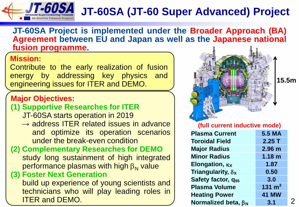
JT-60SA (JT-60 Super Advanced) Project
Major Objectives: (1) Supportive Researches for ITER
JT-60SA starts operation in 2019 → address ITER related issues in advance
and optimize its operation scenarios under the break-even condition
(2) Complementary Researches for DEMO study long sustainment of high integrated performance plasmas with high bN value
(3) Foster Next Generation build up experience of young scientists and technicians who will play leading roles in ITER and DEMO.
Mission: Contribute to the early realization of fusion energy by addressing key physics and engineering issues for ITER and DEMO.
15.5m
JT-60SA Project is implemented under the Broader Approach (BA) Agreement between EU and Japan as well as the Japanese national fusion programme.
2
Plasma Current 5.5 MA
Toroidal Field 2.25 T
Major Radius 2.96 m
Minor Radius 1.18 m
Elongation, kX 1.87
Triangularity, dX 0.50
Safety factor, q95 3.0
Plasma Volume 131 m3
Heating Power 41 MW
Normalized beta, bN 3.1
(full current inductive mode)
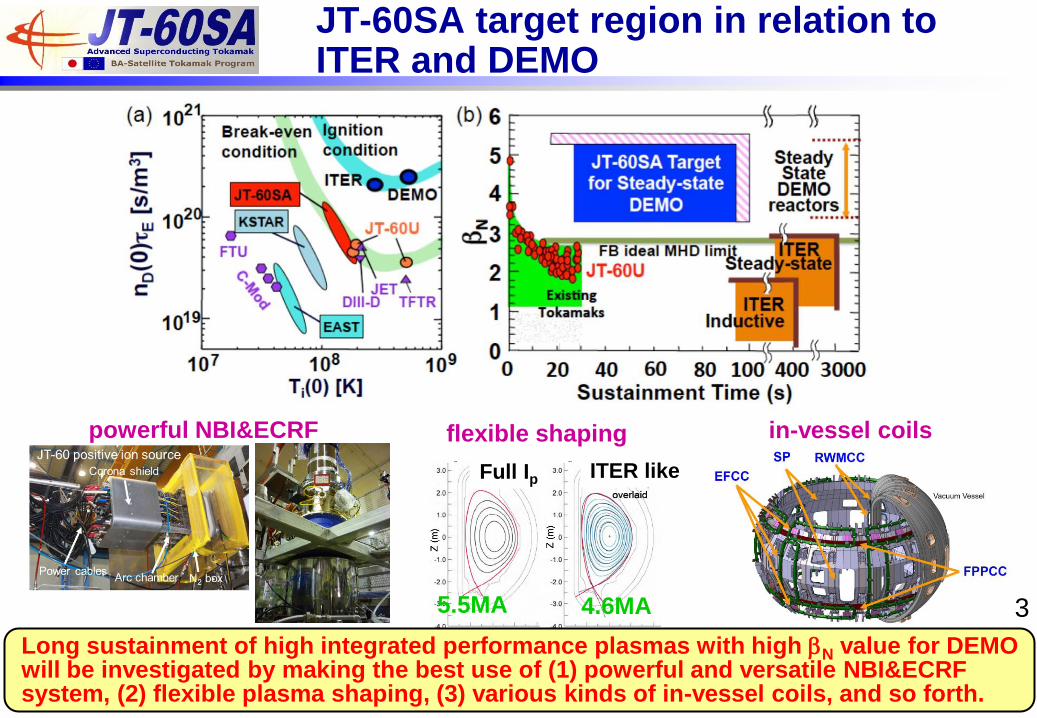
5.5MA 4.6MA
ITER like Full Ip
flexible shaping powerful NBI&ECRF in-vessel coils
JT-60SA target region in relation to ITER and DEMO
Long sustainment of high integrated performance plasmas with high bN value for DEMO will be investigated by making the best use of (1) powerful and versatile NBI&ECRF system, (2) flexible plasma shaping, (3) various kinds of in-vessel coils, and so forth.
3
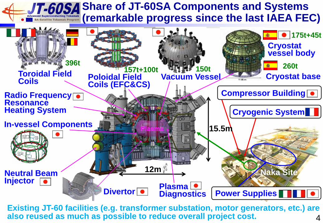
Neutral Beam Injector
Divertor
12m
Plasma
Radio Frequency Resonance Heating System
Plasma Diagnostics
Toroidal Field Coils
396t
Cryostat vessel body
Cryostat base
175t+45t
260t
Poloidal Field Coils (EFC&CS)
Vacuum Vessel 150t
Power Supplies
15.5m
Naka Site
Cryogenic System
Compressor Building
Share of JT-60SA Components and Systems (remarkable progress since the last IAEA FEC)
Existing JT-60 facilities (e.g. transformer substation, motor generators, etc.) are also reused as much as possible to reduce overall project cost.
In-vessel Components
4
157t+100t
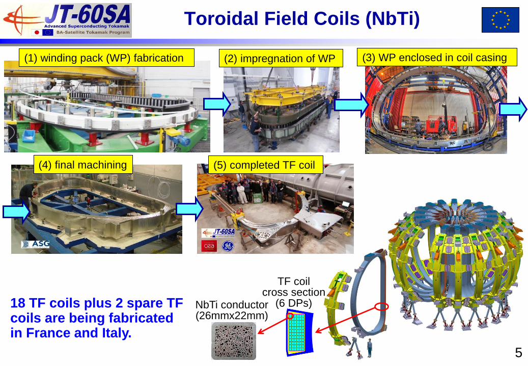
Toroidal Field Coils (NbTi)
(1) winding pack (WP) fabrication (3) WP enclosed in coil casing
(4) final machining (5) completed TF coil
(2) impregnation of WP
5
TF coil cross section
(6 DPs) NbTi conductor (26mmx22mm)
18 TF coils plus 2 spare TF coils are being fabricated in France and Italy.
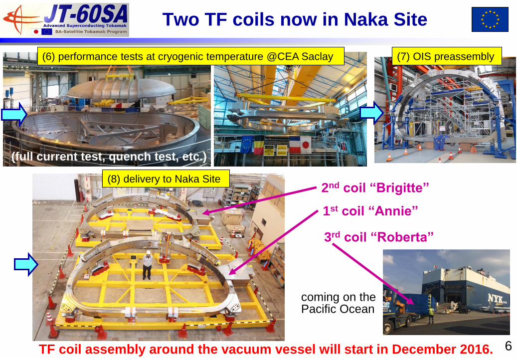
Two TF coils now in Naka Site
(7) OIS preassembly
(full current test, quench test, etc.)
6
(8) delivery to Naka Site
1st coil “Annie”
2nd coil “Brigitte”
(6) performance tests at cryogenic temperature @CEA Saclay
3rd coil “Roberta”
TF coil assembly around the vacuum vessel will start in December 2016.
coming on the Pacific Ocean
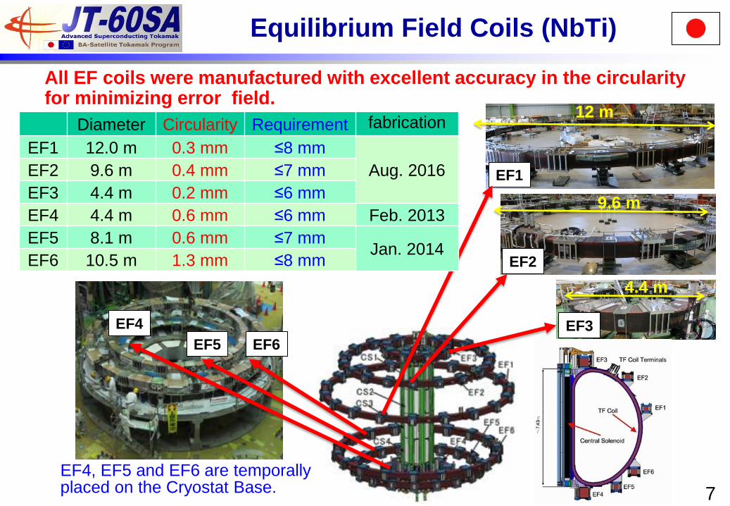
Equilibrium Field Coils (NbTi)
12 m
EF1
EF2
9.6 m
EF3
EF4, EF5 and EF6 are temporally placed on the Cryostat Base.
All EF coils were manufactured with excellent accuracy in the circularity for minimizing error field.
4.4 m
EF6 EF5
EF4
7
Diameter Circularity Requirement fabrication
EF1 12.0 m 0.3 mm ≤8 mm
Aug. 2016 EF2 9.6 m 0.4 mm ≤7 mm
EF3 4.4 m 0.2 mm ≤6 mm
EF4 4.4 m 0.6 mm ≤6 mm Feb. 2013
EF5 8.1 m 0.6 mm ≤7 mm Jan. 2014
EF6 10.5 m 1.3 mm ≤8 mm
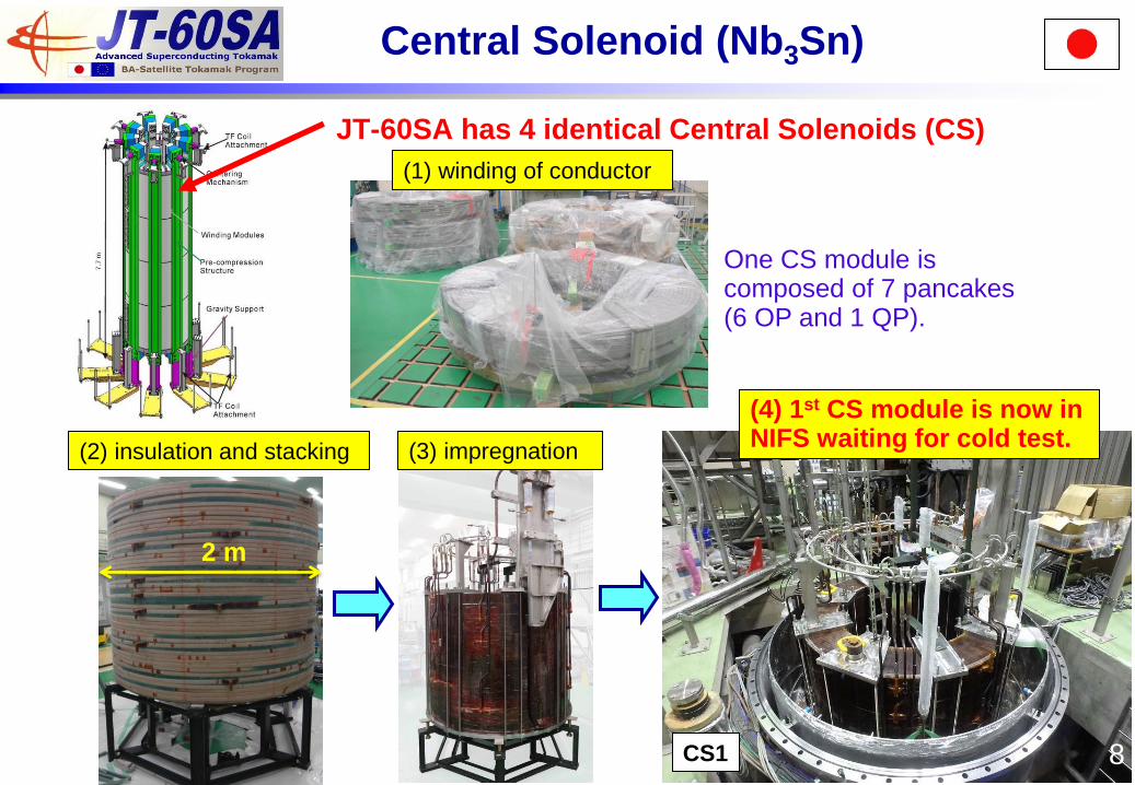
Central Solenoid (Nb3Sn)
CS1
2 m
(4) 1st CS module is now in NIFS waiting for cold test.
JT-60SA has 4 identical Central Solenoids (CS)
One CS module is composed of 7 pancakes (6 OP and 1 QP).
8
(2) insulation and stacking (3) impregnation
(1) winding of conductor
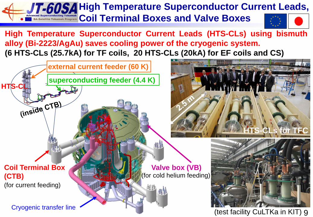
High Temperature Superconductor Current Leads,
Coil Terminal Boxes and Valve Boxes
High Temperature Superconductor Current Leads (HTS-CLs) using bismuth
alloy (Bi-2223/AgAu) saves cooling power of the cryogenic system.
(6 HTS-CLs (25.7kA) for TF coils, 20 HTS-CLs (20kA) for EF coils and CS)
external current feeder (60 K)
superconducting feeder (4.4 K)
HTS-CLs for TFC
(test facility CuLTKa in KIT) 9
HTS-CL
Coil Terminal Box
(CTB)
Cryogenic transfer line
Valve box (VB) (for cold helium feeding)
(for current feeding)
10
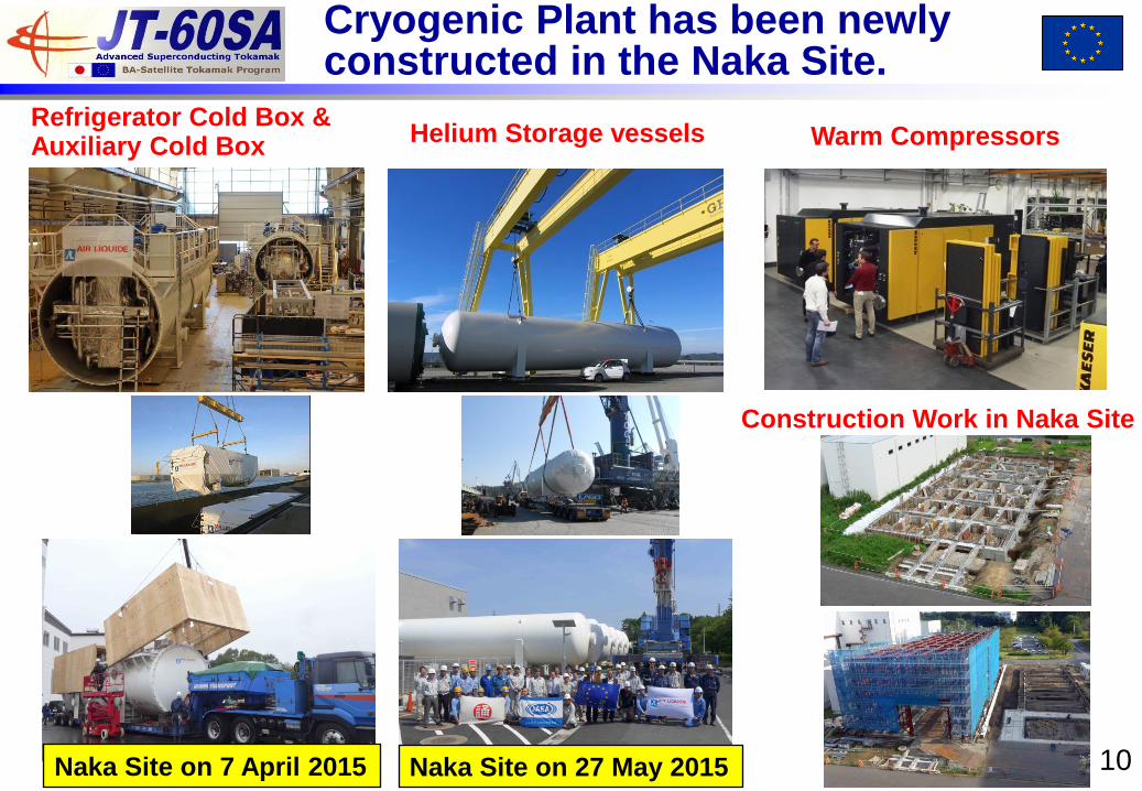
Cryogenic Plant has been newly constructed in the Naka Site.
Refrigerator Cold Box & Auxiliary Cold Box
Helium Storage vessels Warm Compressors
Construction Work in Naka Site
Naka Site on 7 April 2015 Naka Site on 27 May 2015
11
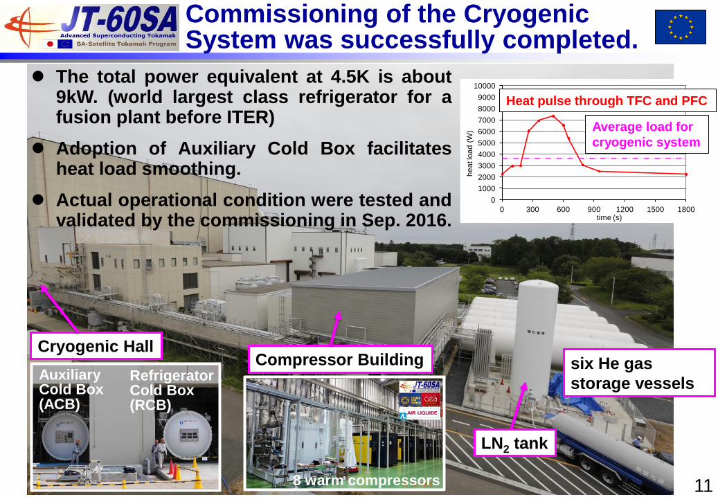
Compressor Building six He gas
storage vessels
Cryogenic Hall
Commissioning of the Cryogenic System was successfully completed.
The total power equivalent at 4.5K is about 9kW. (world largest class refrigerator for a fusion plant before ITER)
Adoption of Auxiliary Cold Box facilitates heat load smoothing.
Actual operational condition were tested and validated by the commissioning in Sep. 2016.
Auxiliary Cold Box (ACB)
Refrigerator Cold Box (RCB)
0
1000
2000
3000
4000
5000
6000
7000
8000
9000
10000
0 300 600 900 1200 1500 1800
he
at lo
ad
(W
)
time (s)
Heat pulse through TFC and PFC
Average load for
cryogenic system
LN2 tank
8 warm compressors
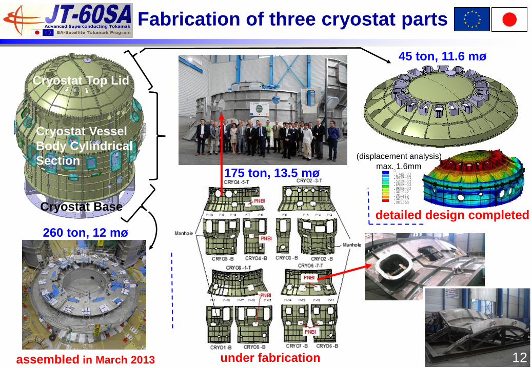
Cryostat Vessel
Body Cylindrical
Section
Cryostat Top Lid
Cryostat Base detailed design completed
assembled in March 2013 under fabrication
260 ton, 12 mø
Fabrication of three cryostat parts
175 ton, 13.5 mø
45 ton, 11.6 mø
max. 1.6mm
(displacement analysis)
12
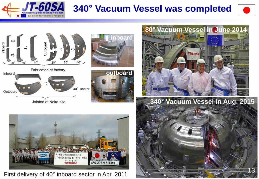
340° Vacuum Vessel was completed
13
340° Vacuum Vessel in Aug. 2015
80° Vacuum Vessel in June 2014
First delivery of 40° inboard sector in Apr. 2011
inboard
outboard
14
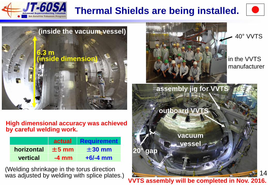
Thermal Shields are being installed.
(inside the vacuum vessel)
VVTS assembly will be completed in Nov. 2016.
assembly jig for VVTS
outboard VVTS
20° gap
vacuum
vessel
6.3 m (inside dimension)
actual Requirement
horizontal ±5 mm ±30 mm
vertical -4 mm +6/-4 mm
High dimensional accuracy was achieved by careful welding work.
in the VVTS
manufacturer
40° VVTS
(Welding shrinkage in the torus direction was adjusted by welding with splice plates.)
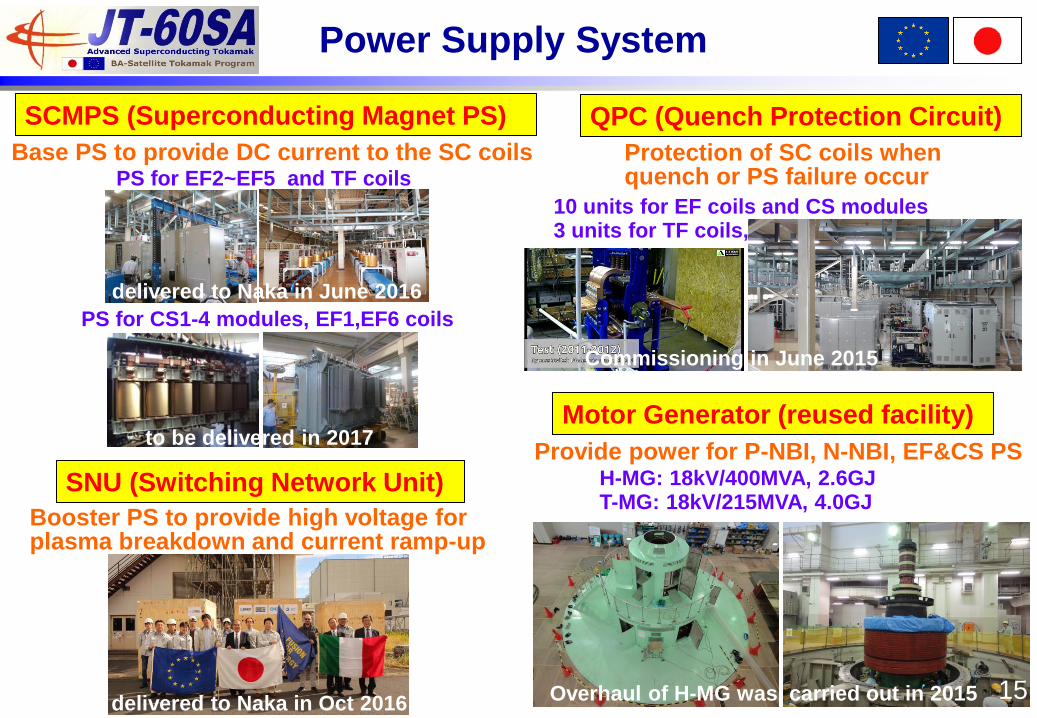
Power Supply System
SCMPS (Superconducting Magnet PS)
PS for CS1-4 modules, EF1,EF6 coils
Shipping ready (52 boxes)
PS for EF2~EF5 and TF coils
Base PS to provide DC current to the SC coils
SNU (Switching Network Unit)
Booster PS to provide high voltage for plasma breakdown and current ramp-up
QPC (Quench Protection Circuit)
Commissioning in June 2015
10 units for EF coils and CS modules 3 units for TF coils,
Protection of SC coils when quench or PS failure occur
to be delivered in 2017
delivered to Naka in June 2016
Motor Generator (reused facility)
H-MG: 18kV/400MVA, 2.6GJ T-MG: 18kV/215MVA, 4.0GJ
Provide power for P-NBI, N-NBI, EF&CS PS
Overhaul of H-MG was carried out in 2015 15 delivered to Naka in Oct 2016
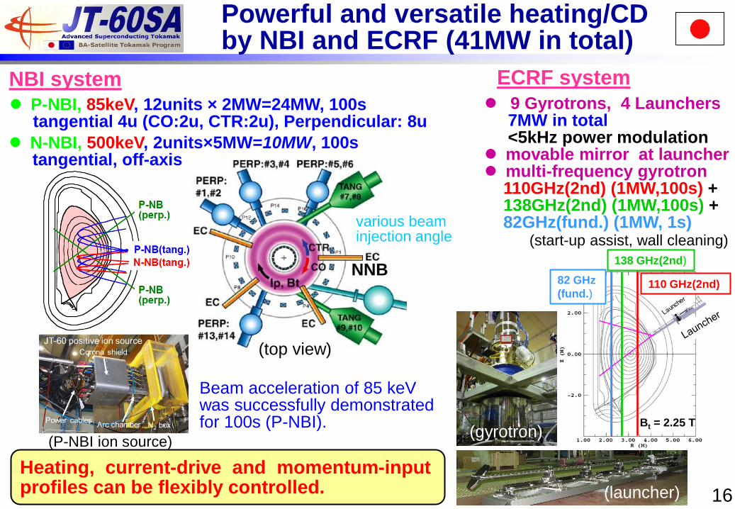
NNB
(top view)
Powerful and versatile heating/CD by NBI and ECRF (41MW in total)
NBI system P-NBI, 85keV, 12units × 2MW=24MW, 100s tangential 4u (CO:2u, CTR:2u), Perpendicular: 8u
N-NBI, 500keV, 2units×5MW=10MW, 100s tangential, off-axis
ECRF system
9 Gyrotrons, 4 Launchers 7MW in total <5kHz power modulation movable mirror at launcher multi-frequency gyrotron 110GHz(2nd) (1MW,100s) + 138GHz(2nd) (1MW,100s) + 82GHz(fund.) (1MW, 1s)
16 (launcher)
Heating, current-drive and momentum-input profiles can be flexibly controlled.
Beam acceleration of 85 keV was successfully demonstrated for 100s (P-NBI).
(start-up assist, wall cleaning)
Bt = 2.25 T
138 GHz(2nd)
110 GHz(2nd) 82 GHz
(fund.)
(P-NBI ion source)
various beam injection angle
(gyrotron)
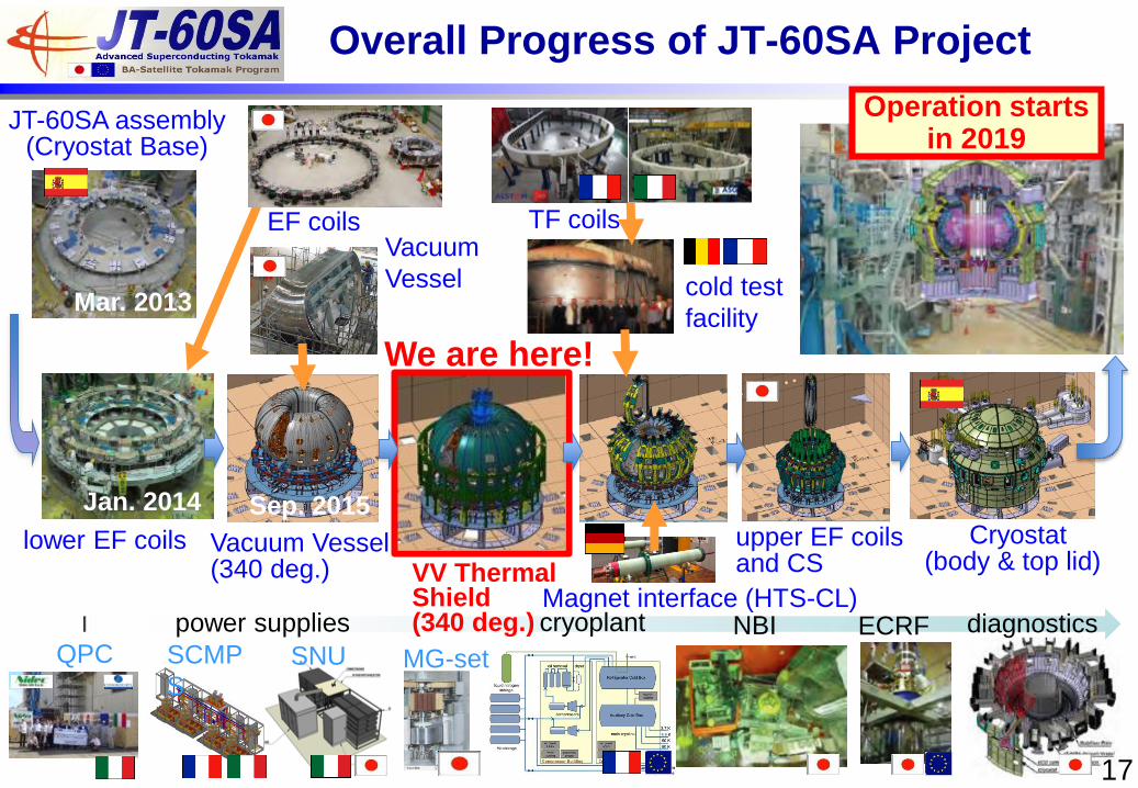
upper EF coils and CS
cold test
facility
Vacuum
Vessel
Cryostat (body & top lid)
TF coils
Mar. 2013
Jan. 2014
17
Operation starts in 2019
EF coils
Overall Progress of JT-60SA Project
Vacuum Vessel (340 deg.)
Magnet interface (HTS-CL)
Sep. 2015
SNU SCMP
S MG-set
power supplies
QPC diagnostics NBI ECRF cryoplant
JT-60SA assembly (Cryostat Base)
lower EF coils
VV Thermal Shield (340 deg.)
We are here!
18
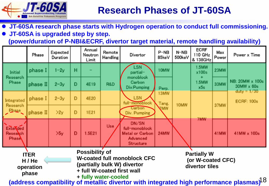
Partially W (or W-coated CFC) divertor tiles
Possibility of W-coated full monoblock CFC (partially bulk W) divertor + full W-coated first wall + fully water-cooled
ITER H / He
operation phase
JT-60SA research phase starts with Hydrogen operation to conduct full commissioning.
JT-60SA is upgraded step by step.
(power/duration of P-NBI&ECRF, divertor target material, remote handling availability)
Research Phases of JT-60SA
(address compatibility of metallic divertor with integrated high performance plasmas)
19
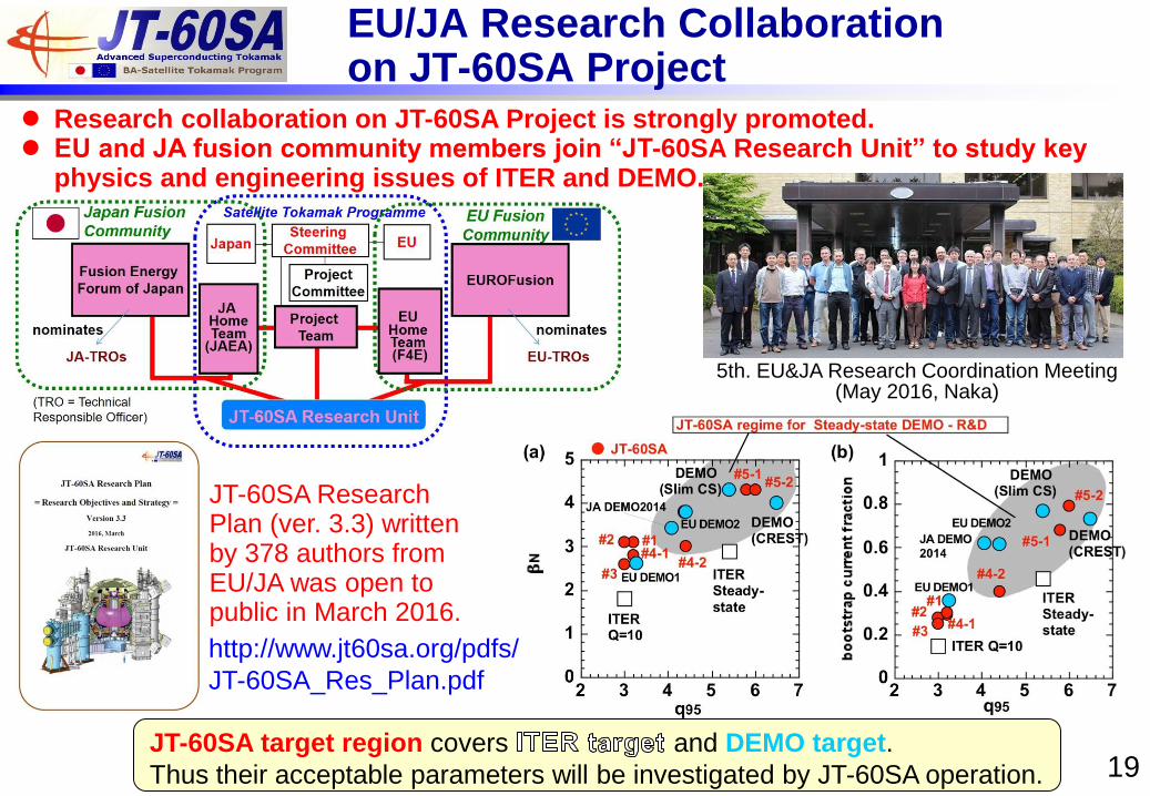
EU/JA Research Collaboration on JT-60SA Project
Research collaboration on JT-60SA Project is strongly promoted. EU and JA fusion community members join “JT-60SA Research Unit” to study key
physics and engineering issues of ITER and DEMO.
JT-60SA Research Plan (ver. 3.3) written by 378 authors from EU/JA was open to public in March 2016.
5th. EU&JA Research Coordination Meeting (May 2016, Naka)
http://www.jt60sa.org/pdfs/
JT-60SA_Res_Plan.pdf
JT-60SA target region covers and DEMO target.
Thus their acceptable parameters will be investigated by JT-60SA operation.
20
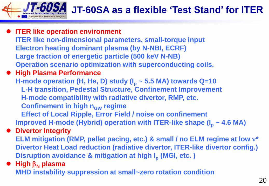
JT-60SA as a flexible ‘Test Stand’ for ITER
ITER like operation environment
ITER like non-dimensional parameters, small-torque input
Electron heating dominant plasma (by N-NBI, ECRF)
Large fraction of energetic particle (500 keV N-NB)
Operation scenario optimization with superconducting coils.
High Plasma Performance
H-mode operation (H, He, D) study (Ip ~ 5.5 MA) towards Q=10
L-H transition, Pedestal Structure, Confinement Improvement
H-mode compatibility with radiative divertor, RMP, etc.
Confinement in high nGW regime
Effect of Local Ripple, Error Field / noise on confinement
Improved H-mode (Hybrid) operation with ITER-like shape (Ip ~ 4.6 MA)
Divertor Integrity
ELM mitigation (RMP, pellet pacing, etc.) & small / no ELM regime at low n*
Divertor Heat Load reduction (radiative divertor, ITER-like divertor config.)
Disruption avoidance & mitigation at high Ip (MGI, etc. )
High bN plasma
MHD instability suppression at small~zero rotation condition
21
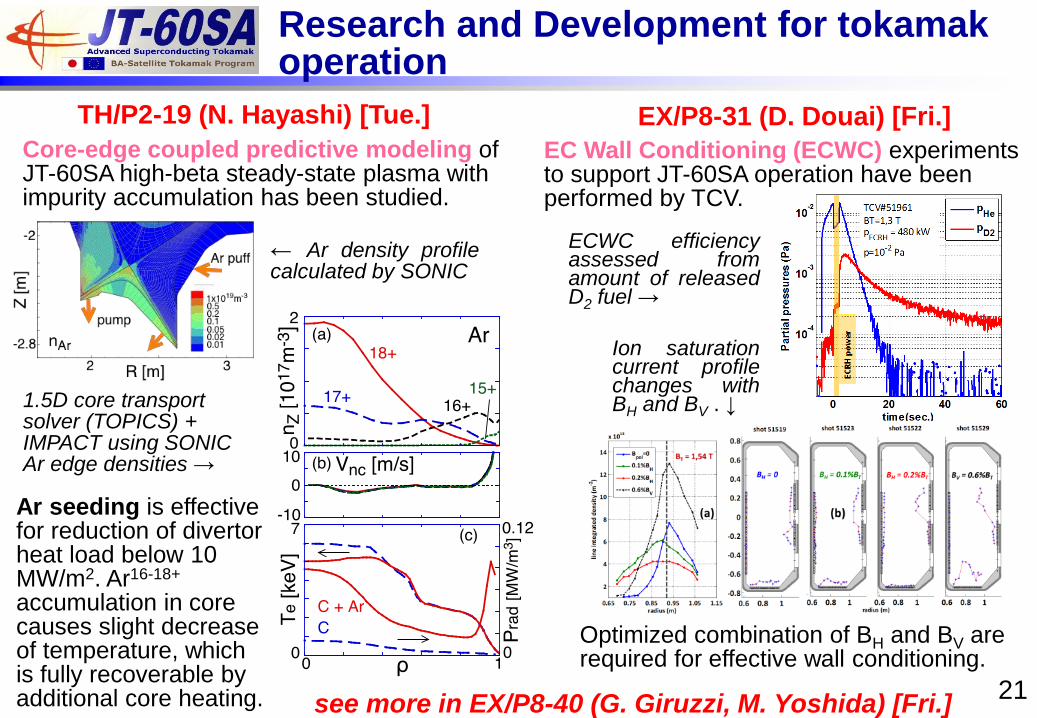
ECWC efficiency assessed from amount of released D2 fuel →
Research and Development for tokamak operation
see more in EX/P8-40 (G. Giruzzi, M. Yoshida) [Fri.]
Core-edge coupled predictive modeling of JT-60SA high-beta steady-state plasma with impurity accumulation has been studied.
TH/P2-19 (N. Hayashi) [Tue.] EX/P8-31 (D. Douai) [Fri.]
1.5D core transport solver (TOPICS) + IMPACT using SONIC Ar edge densities →
← Ar density profile calculated by SONIC
Ar seeding is effective for reduction of divertor heat load below 10 MW/m2. Ar16-18+ accumulation in core causes slight decrease of temperature, which is fully recoverable by additional core heating.
EC Wall Conditioning (ECWC) experiments to support JT-60SA operation have been performed by TCV.
Optimized combination of BH and BV are required for effective wall conditioning.
Ion saturation current profile changes with BH and BV . ↓
1. Fabrication, installation and commissioning of JT-60SA components and systems procured by EU and Japan are steadily progressing. TF coil assembly around the vacuum vessel will start soon. JT-60SA starts operation in 2019.
2. Powerful and versatile NBI/ECRF system, flexible plasma shaping, various kinds of in-vessel coils are advantage of JT-60SA for plasma control.
3. JT-60SA will explore ITER and DEMO relevant parameter region in advance for the purpose of optimization of their operational scenarios, especially in high bN (~5) region.
4. Close research collaboration between EU and Japan has been promoted. JT-60SA Research Plan v.3.3 by 378 researchers from EU and Japan released in March 2016 elaborates on key physics and engineering issues to be addressed for ITER and DEMO.
Summary of JT-60SA Project
22
JT-60SA related presentations in this conference
18 Oct (Tue) FIP/1-3Ra (J. Hiratsuka) Long-pulse acceleration of 1MeV negative ion beams toward ITER and JT-
60SA neutral beam injectors & towards powerful negative ion beams at the test facility ELISE for the ITER and DEMO NBI system
TH/P1-18 (T. Bolzonella) Securing high bN JT-60SA operational space by MHD stability and active control modelling
TH/P2-19 (N. Hayashi) Core-edge coupled predictive modeling of JT-60SA high-beta steady-state plasma with impurity accumulation
TH/P2-20 (M. Romanelli) Investigation of Sustainable Reduced-Power non-inductive Scenarios on JT-60SA
19 Oct (Wed) FIP/P4-42 (C. Day) Assessment of the operational window for JT-60SA divertor pumping under
consideration of the effects from neutral-neutral collisions
20 Oct (Thu) TH/P6-24 (R. Zagorski) Numerical analyses of baseline JT-60SA design concepts with the COREDIV
code
21 Oct (Fri) FIP/P7-37 (J.-C. Vallet) Towards the completion of the CEA Contributions to the Broader Approach
Projects EX/P8-31 (D. Douai) Development of Helium Electron Cyclotron Wall Conditioning on TCV for the
operation of JT-60SA EX/P8-40 (G. Giruzzi) Physics and operation oriented activities in preparation of the JT-60SA
tokamak exploitation FIP/4-1Ra (Y. Shibama) Assembly Technologies of the Superconducting Tokamak on JT-60SA FIP/4-1Rb (P. Decool) JT-60SA TF Coil Manufacture, Test and Preassembly by CEA 23