journal of the electrochemical society, a2427 0013 … · ability to provide some answers to...
TRANSCRIPT

Journal of The Electrochemical Society, 152 �12� A2427-A2440 �2005� A2427
Modeling Elementary Heterogeneous Chemistryand Electrochemistry in Solid-Oxide Fuel CellsHuayang Zhu,a,* Robert J. Kee,a,*,z Vinod M. Janardhanan,b
Olaf Deutschmann,b,* and David G. Goodwinc
aEngineering Division, Colorado School of Mines Golden, Colorado 80401, USAbInstitute for Chemical Technology, University of Karlsruhe, Karlsruhe, GermanycEngineering and Applied Science, California Institute of Technology Pasadena, California 91125, USA
This paper presents a new computational framework for modeling chemically reacting flow in anode-supported solid-oxide fuelcells �SOFC�. Depending on materials and operating conditions, SOFC anodes afford a possibility for internal reforming orcatalytic partial oxidation of hydrocarbon fuels. An important new element of the model is the capability to represent elementaryheterogeneous chemical kinetics in the form of multistep reaction mechanisms. Porous-media transport in the electrodes isrepresented with a dusty-gas model. Charge-transfer chemistry is represented in a modified Butler-Volmer setting that is derivedfrom elementary reactions, but assuming a single rate-limiting step. The model is discussed in terms of systems with defined flowchannels and planar membrane-electrode assemblies. However, the underlying theory is independent of the particular geometry.Examples are given to illustrate the model.© 2005 The Electrochemical Society. �DOI: 10.1149/1.2116607� All rights reserved.
Manuscript received May 4, 2005; revised manuscript received August 8, 2005. Available electronically November 4, 2005.
0013-4651/2005/152�12�/A2427/14/$7.00 © The Electrochemical Society, Inc.
Solid oxide fuel cells �SOFC� can be operated with a variety offuels, including hydrogen, CO, hydrocarbons, or mixtures of these.This is possible because of the relatively high operating tempera-tures, and, at least in conventional SOFC anodes, the use of transi-tion metal catalysts that promote the water–gas-shift reaction
CO + H2O � CO2 + H2 �1�
and steam reforming, which for methane may be written globally as
CH4 + H2O � CO + 3H2 �2�
If sufficient steam is produced electrochemically at the anode/electrolyte interface by the reaction
H2 + O2− � H2O + 2e− �3�
then reforming and shifting can, in principle, lead to full �if indirect�electrochemical oxidation of a hydrocarbon fuel.
However, competing reaction pathways catalyzed by transitionmetals may also lead to solid carbon deposition, which can quicklydestroy the anode. For this reason, some degree of upstream fuelprocessing, eiher by catalytic partial oxidation or by steam reform-ing, is usually used to produce a fuel stream that is rich in H2 andCO and dilute in residual hydrocarbons before reaching the SOFC.Because upstream processing adds to the complexity, size, and costof the overall plant, it is of considerable interest to minimize or eveneliminate the need for it. There is evidence that mixing some oxygenwith a hydrocarbon fuel can deliver good performance.1 In this casethere must be partial oxidation within the anode structrue. Anotherpromising alternative to utilize hydrocarbon fuels “directly” inSOFCs is to use a ceria oxidation catalyst instead of a transitionmetal.2
Whether an SOFC uses a “reforming anode” with a transitionmetal catalyst, or a “direct oxidation” anode with a ceria-based cata-lyst, or perhaps uses a different, novel anode design, optimizing thesystem to run efficiently on hydrocarbon or hydrocarbon-derivedfuels is a very challenging problem, due to the complex, coupledphysico-chemical processes involved. When significant CO and/orhydrocarbons are present in the fuel, models must also account forthe in situ production of hydrogen through reforming and shiftingreactions within the anode, as well as solid-carbon formation.
Many questions of interest for optimization studies cannot cur-rently be answered easily. For example, for a given anode design,what degree of upstream fuel processing is required to avoid carbondeposition, and how does this depend on operating conditions? What
* Electrochemical Society Active Member.z E-mail: [email protected]
anode design �choice of catalyst, anode thickness, porosity, etc.�minimizes the need for upstream fuel processing? What is the effectof fuel depletion, load conditions, temperature, or flow rates? Ananode might be functionally graded through its thickness; whatgrading of porosity or catalyst loading is optimal?
In practice, questions like these are usually answered by exten-sive testing, often with minimal guidance from theory. Clearly, theability to provide some answers to questions such as these based onan understanding of the underlying chemical and physical processes,even if approximate, is of great value in reducing the time andexpense associated with SOFC development.
Although the present state of knowledge of the physical andchemical processes responsible for SOFC performance is incom-plete, enough is known to begin to put together physically basedmodels that can integrate experimental data from multiple sources,and make useful engineering performance predictions. For example,results from pattern-anode studies of hydrogen oxidation at Ni-YSZanodes have led to mechanistic insights into the mechanism ofcharge transfer; these insights may be applied to construct activationpolarization models for Ni-YSZ cermet anodes that may be used inplace of semiempirical models. Also, detailed studies of the hetero-geneous kinetics of shifting and reforming chemistry on transitionmetals have been carried out; the resulting reaction mechanisms canbe used directly in SOFC models, provided they are constructed in amanner that allows use of detailed reaction mechanisms.
In this paper, we present a modeling framework for SOFC simu-lation that is a step toward the physically based, predictive, quanti-tative models that are needed for SOFC optimization and design.Unlike most existing SOFC models that rely heavily on empiricalsystems-level data, here we begin at the microscale, incorporatingwhat is known about important elementary steps �charge transfer,heterogeneous chemistry, porous media transport� into the model ina manner that accounts for the strong nonlinear couplings betweenthem, and that allows assessing the sensitivity of macroscale perfor-mance: open circuit potentials, current-voltage characteristics, fuelutilization, efficiency, etc., to microscale phenomena.
Our focus is particularly on SOFCs using reforming anodes, butthe approach applies generally to direct-oxidation anodes as wellwith minor modifications. The model takes as input a set of physical,chemical, and operating parameters �channel dimensions, reactionrates, electrode porosity, load potential, fuel composition and flowrates, etc.�, and produces as output measurable performance param-eters: current density profiles, efficiencies, exhaust gas composi-tions, that can be compared to experiment.
Developing physically based models of processes as complex asSOFCs is inevitably an iterative process, incorporating new infor-mation as it is available. Basing the model on fundamental physics

A2428 Journal of The Electrochemical Society, 152 �12� A2427-A2440 �2005�A2428
and chemistry enables simulating a wider range of conditions than ispossible with more empirical models. However, validation and re-finement of model assumptions and parameter values is required atevery step of the process. The approaches discussed in this paperprovides a starting point and a framework that is capable ofenhancement and refinement as new fundamental data becomeavailable.
Prior SOFC modeling.— In very broad terms, SOFC modelingis pursued along three general avenues. Stack level models are basedon three-dimensional computational fluid dynamics �CFD� capabili-ties, often using commercial software packages �e.g., Fluent, STAR-CD�. These models, which couple fluid flow, conductive and radia-tive heat transfer, and chemistry, are used to assist system design.3-7
Such models accommodate complex flow passages and cell layouts.In addition to electrochemical performance, predicting temperaturedistributions, pressure drops, and stress distributions is alsoimportant.
A number of investigators have developed models to study flowand chemistry within porous cermet composite electrodes.8-16 Thesemodels may include the gas-phase species transport through the porephase, surface diffusion of adsorbed species, Ohm’s law for thecharge transport within the ionic and electronic conducting phases,charge balance, and charge-transfer kinetics. The models are formu-lated in a continuum differential-equation setting, and usually in onespatial dimension through the electrode thickness. Such models areused to investigate the effects of electrode structure and materialproperties on membrane-electrode assembly �MEA� performance.
Several groups have developed microscopic models to studycharge-transfer processes in the vicinity of three-phaseboundaries.17-27 These TPB models may include adsorption/desorption of the gas-phase species, surface reactions and diffusionof the adsorbed species, and the charge-transfer electrochemical re-actions. The geometrical setting may represent patterned electrodesor may consider a few individual particles of a cermet. Thesemodels are very helpful in the interpretation of electrochemicalimpedance spectroscopy �EIS� measurements or polarizationmeasurements.
With only a few exceptions, the charge-transfer kinetics in allthese models begins with a Nernst potential based on gas-phasecomposition and activation overpotentials represented in Butler-Volmer form. Thermal chemistry is usually handled with significantsimplifying assumptions, such as global reaction kinetics or localequilibration of reforming and water–gas-shift chemistry. The workreported in the present paper emphasizes the incorporation of el-ementary chemical kinetics.
Model Description
Although much of the modeling approach described here couldbe used with any SOFC configuration, we focus in this paper on onespecific configuration: a planar, anode-supported SOFC with adefined-channed coflowing architecture, as illustrated in Fig. 1. Afuel mixture flows from left to right in the fuel channel at the top,and is transported into the pores of the anode by a combination ofFickian and Knudsen diffusion together with convective Darcy flow.Within the anode it may undergo reaction on the catalyst-particlesurfaces, and one or more species in the fuel mixture, either initiallypresent or created in situ, may be electrochemically oxidized uponreaching the inner region of the anode near the dense electrolyte. Weassume here that this electrochemically active region is much thin-ner than the total anode thickness, limited by the need to conductoxygen ions from the dense electrolyte through the oxide particlepore network. In an anode-supported architecture the porous anodeis on the order of a millimeter thick. The charge-transfer region iscomprised of distributed three-phase interfaces limited to a fewmicrometers.9 Thus, on the scale of the relatively thick anode struc-ture, the charge-transfer region can be approximated as a thin inter-face. The electrons produced by electrochemical oxidation reactionsare collected by the network of electronically conducting particles�e.g., Ni or Cu�, which may or may not be the same as the catalyst
particles. In principle, the porosity, particle, and pore sizes, andchemical composition of the anode may all vary through the thick-ness �i.e., functional grading�.
On the cathode side, oxygen from the air is reduced electrocata-lytically to draw electrons from the cathode and to produce theoxygen ions that enter the dense electrolyte, and flow across it toreplenish the ions lost on the anode side.
Along the length of the fuel channel, the fuel stream becomesincreasingly diluted with reaction products �i.e., H2O and CO2�, anddepleted in fuel. The air channel also becomes depleted in oxygen�although it is typical to operate cells with an oversupply of air sothat the relative increase in the N2 fraction is usually a small effect�.As a result, the difference in oxygen ion electrochemical potentialacross the electrolyte drops, reducing the ability to extract furtherelectrical power. This drop in the thermodynamic driving force,along with variation in various internal losses �overpotentials� alongthe length of a channel results in the local current density varyingalong the length of the channel.
Channel flow.— The gas flow in the fuel and air channels isconsidered to be one-dimensional and laminar, neglecting variationsof the gas composition transverse to the flow direction. This is agood approximation, because fuel and air channels typically havecharacteristic diameters less than a centimeter and mean velocitiesof less than 100 cm/s. Under these circumstances, the Reynoldsnumber is on the order of 100 or less. Consequently, the flow ishighly viscous and a fully developed velocity profile is establishedvery near the channel entrance. Rapid diffusion of species across thechannel width homogenizes the composition transverse to the flow.
The steady plug-flow model within the channels can be summa-rized as28-30
d��Yku�dx
=Pe
AcJkWk k = 1, . . . ,Kg �4�
d��u�dx
= �k=1
KgPe
AcJkWk �5�
The independent variable is distance along the channel x, and thedependent variables are mean velocity u, and Kg species mass frac-tions Yk. The local density � is determined from a perfect-gas equa-tion of state
� =p
RT
1
� Yk/Wk
�6�
The species molecular weights are Wk.The channel geometry is characterized by the cross-sectional
area A , and the perimeter associated with the electrochemically
Figure 1. Cutaway view of an anode-supported solid-oxide fuel cell section,showing some possible heterogeneous reaction processes.
c

A2429Journal of The Electrochemical Society, 152 �12� A2427-A2440 �2005� A2429
active MEA is represented by Pe. In Fig. 2 Pe includes the width ofthe gas channel plus the width of the electrode that lies under theinterconnect rib.
As illustrated in Fig. 2, the variables Jk are the species molefluxes that enter �or leave� the flow channels to �or from� the MEAstructure. These fluxes depend on the local electric-current densityi�x� and heterogeneous chemistry within the porous-electrode struc-ture. The mass-exchange between the MEA and the channelscouples the conservation equations for the channel flow and thereacting porous-media flow in the electrodes.
Although species diffusion in the flow direction could be retainedin Eq. 4, it is usually negligible under SOFC conditions. Even forlight species like hydrogen, the diffusion velocities are around1 cm/s, with typical convective velocities on the order of10 to 100 cm/s.
The model could also incorporate gas-phase chemistry within thechannels. Especially for light hydrocarbons, the elementary homo-geneous chemistry is relatively well understood. However, withmethane as a fuel and residence times of a few seconds, there isrelatively little homogeneous reaction below around 800°C.31 How-ever, for higher temperatures or for higher hydrocarbon fuels, ho-mogeneous chemistry can play a substantially larger role. Whenconsidering the formation of polyaromatic deposits, homogeneousreaction plays a large role.32,33 Gas-phase chemistry may also playan important role under partial-oxidation conditions where oxygen ismixed with the fuel. Beyond the need for a reaction mechanism andincreasing the problem size, including homogeneous chemistry addsno essential complications to the modeling or the solution algorithm.
The system can be extended to include momentum and energyequations that are solved to predict pressure and temperature pro-files. The boundary conditions depend on system-wide consider-ations, such as position in the stack, interconnect materials, externalinsulation, etc. In this paper, which is particularly concerned withthe incorporation of detailed chemistry and considers a single set ofchannels, the pressure and temperature are assumed to be uniform.
Porous electrodes.— Within the porous electrodes, the steady-state fluxes of each species satisfy
� · Jk = Assgas,k, k = 1, . . . ,Kg �7�
where Jk is the net molar flux vector for gaseous species k, sgas,k isits net production rate due to heterogeneous chemistry, and As is theactive catalyst area per unit volume.
The molar fluxes are evaluated using the dusty gas model�DGM�, in which the fluxes are driven by gradients in concentra-tions and pressure.34 Because the electrode thickness is muchsmaller than its length, the gradients are primarily in the y direction,and therefore the transport through the electrode is approximatelyone-dimensional. In this case, Eq. 7 may be simplified to
dJk,y
dy= Assgas,k k = 1, . . . ,Kg �8�
The molar production rates are evaluated using a heterogeneous re-action mechanism �e.g., Table I�. Since this mechanism is formu-
Figure 2. Finite volume representation used for simulation.
lated in terms of elementary reactions on the catalyst surface, thereaction rates depend both on the concentrations of the gaseous re-actants and on the coverages of the surface species representingreactive surface sites and adsorbates. Since these coverages are notknown a priori, they must be determined as part of the solution.
Unlike the gaseous species, the surface species are effectivelyimmobile on length scales larger than an individual catalyst particle.Therefore, at steady state, the surface coverages must take on valuessuch that the net production rate due to chemistry is zero for everysurface species
ssurf,k = 0, k = 1, . . . ,Ks �9�
Here, Ks is the total number of surface species.The net production rate of any species �gas or surface� is given
by
sk = �i
�kiqi �10�
where qi is the rate of reaction i and �ki is the net stoichiometriccoefficient of the species in question in reaction i �positive for prod-ucts, negative for reactants�. The reaction rates qi are computedassuming mass-action kinetics,30 with temperature-dependent ratecoefficients in Arrhenius form ki = AiT
n exp�−Ei/RT�. As discussedbelow, for some reactions the activation energy is allowed to dependon species coverages.
The dusty gas model.— The fluxes Jk are computed using the dustygas model,34 which is a multicomponent transport model derivedfrom kinetic theory to describe the transport of a gas mixturethrough a porous matrix consisting of stationary and uniformly dis-tributed particles. It may be used over the full range of Knudsennumber, from values much larger than 1 �molecule-wall collisionsdominate�, to values much less than 1 �molecule-molecule collisionsdominate�, and also includes the flow induced by a pressure gradient�Darcy flow�.
The DGM can be written as an implicit relationship among themolar concentrations, molar fluxes, concentrations gradients, and thepressure gradient35,36
���k
�X��Jk − �Xk�J�
�XT�Dk�e +
Jk
Dk,Kne = − � �Xk� −
�Xk�Dk,Kn
e
Bg
�� p
�11�
In this relationship Jk is the molar flux of gas-phase species k, �Xk�are the molar concentrations, and �XT� = p/RT is the total molarconcentration. The mixture viscosity is given as �, and Dk�
e andDk,Kn
e are the effective molecular binary diffusion coefficients andKnudsen diffusion coefficients. The permeability of the porous net-work is given as Bg.
The effective molecular binary diffusion coefficients in the po-rous media Dk�
e are related to the ordinary binary diffusion coeffi-cients Dk� in the gas phase as
Dk�e =
�g
�gDk� �12�
The porous media porosity is given as �g and the tortuousity isgiven as �g. The ordinary binary diffusion coefficients Dk� and theviscosity � may be determined from standard expressions derivedfrom kinetic theory.30 Software packages that compute these are alsoavailable.37,38
Knudsen diffusion, which occurs due to gas-wall collisions, be-comes dominant when the mean-free path of the molecular speciesis much larger than the pore diameter. The effective Knudsen diffu-sion coefficient can be expressed as
Dk,Kne =
4
3
�g
�grp� 8RT
�Wk�13�
where r is the average pore radius.
p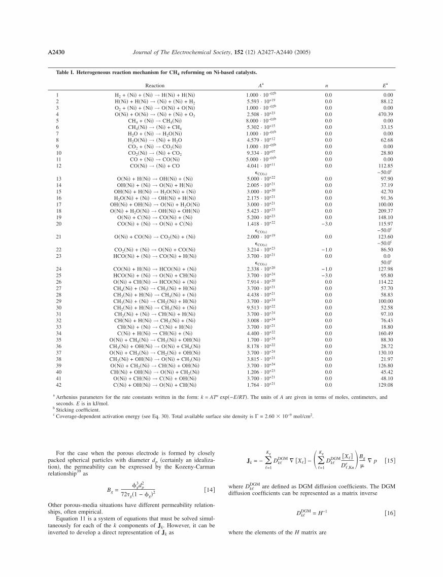
ce site
A2430 Journal of The Electrochemical Society, 152 �12� A2427-A2440 �2005�A2430
For the case when the porous electrode is formed by closelypacked spherical particles with diameter dp �certainly an idealiza-tion�, the permeability can be expressed by the Kozeny-Carmanrelationship39 as
Bg =�g
3dp2
72�g�1 − �g�2 �14�
Other porous-media situations have different permeability relation-ships, often empirical.
Equation 11 is a system of equations that must be solved simul-taneously for each of the k components of Jk. However, it can beinverted to develop a direct representation of J as
Table I. Heterogeneous reaction mechanism for CH4 reforming on N
Reaction
1 H2 + �Ni� + �Ni� → H�Ni� + H�Ni�2 H�Ni� + H�Ni� → �Ni� + �Ni� + H2
3 O2 + �Ni� + �Ni� → O�Ni� + O�Ni�4 O�Ni� + O�Ni� → �Ni� + �Ni� + O2
5 CH4 + �Ni� → CH4�Ni�6 CH4�Ni� → �Ni� + CH4
7 H2O + �Ni� → H2O�Ni�8 H2O�Ni� → �Ni� + H2O9 CO2 + �Ni� → CO2�Ni�10 CO2�Ni� → �Ni� + CO2
11 CO + �Ni� → CO�Ni�12 CO�Ni� → �Ni� + CO
13 O�Ni� + H�Ni� → OH�Ni� + �Ni�14 OH�Ni� + �Ni� → O�Ni� + H�Ni�15 OH�Ni� + H�Ni� → H2O�Ni� + �Ni�16 H2O�Ni� + �Ni� → OH�Ni� + H�Ni�17 OH�Ni� + OH�Ni� → O�Ni� + H2O�Ni�18 O�Ni� + H2O�Ni� → OH�Ni� + OH�Ni�19 O�Ni� + C�Ni� → CO�Ni� + �Ni�20 CO�Ni� + �Ni� → O�Ni� + C�Ni�
21 O�Ni� + CO�Ni� → CO2�Ni� + �Ni�
22 CO2�Ni� + �Ni� → O�Ni� + CO�Ni�23 HCO�Ni� + �Ni� → CO�Ni� + H�Ni�
24 CO�Ni� + H�Ni� → HCO�Ni� + �Ni�25 HCO�Ni� + �Ni� → O�Ni� + CH�Ni�26 O�Ni� + CH�Ni� → HCO�Ni� + �Ni�27 CH4�Ni� + �Ni� → CH3�Ni� + H�Ni�28 CH3�Ni� + H�Ni� → CH4�Ni� + �Ni�29 CH3�Ni� + �Ni� → CH2�Ni� + H�Ni�30 CH2�Ni� + H�Ni� → CH3�Ni� + �Ni�31 CH2�Ni� + �Ni� → CH�Ni� + H�Ni�32 CH�Ni� + H�Ni� → CH2�Ni� + �Ni�33 CH�Ni� + �Ni� → C�Ni� + H�Ni�34 C�Ni� + H�Ni� → CH�Ni� + �Ni�35 O�Ni� + CH4�Ni� → CH3�Ni� + OH�Ni�36 CH3�Ni� + OH�Ni� → O�Ni� + CH4�Ni�37 O�Ni� + CH3�Ni� → CH2�Ni� + OH�Ni�38 CH2�Ni� + OH�Ni� → O�Ni� + CH3�Ni�39 O�Ni� + CH2�Ni� → CH�Ni� + OH�Ni�40 CH�Ni� + OH�Ni� → O�Ni� + CH2�Ni�41 O�Ni� + CH�Ni� → C�Ni� + OH�Ni�42 C�Ni� + OH�Ni� → O�Ni� + CH�Ni�
a Arrhenius parameters for the rate constants written in the form: k = ATseconds. E is in kJ/mol.
b Sticking coefficient.c Coverage-dependent activation energy �see Eq. 30�. Total available surfa
k
Jk = − ��=1
Kg
Dk�DGM � �X�� − ��
�=1
Kg
Dk�DGM �X��
D�,Kne �Bg
�� p �15�
where Dk�DGM are defined as DGM diffusion coefficients. The DGM
diffusion coefficients can be represented as a matrix inverse
Dk�DGM = H−1 �16�
where the elements of the H matrix are
ed catalysts.
Aa n Ea
1.000 · 10−02b 0.0 0.005.593 · 10+19 0.0 88.121.000 · 10−02b 0.0 0.002.508 · 10+23 0.0 470.398.000 · 10−03b 0.0 0.005.302 · 10+15 0.0 33.151.000 · 10−01b 0.0 0.004.579 · 10+12 0.0 62.681.000 · 10−05b 0.0 0.009.334 · 10+07 0.0 28.805.000 · 10−01b 0.0 0.004.041 · 10+11 0.0 112.85
�CO�s� −50.0c
5.000 · 10+22 0.0 97.902.005 · 10+21 0.0 37.193.000 · 10+20 0.0 42.702.175 · 10+21 0.0 91.363.000 · 10+21 0.0 100.005.423 · 10+23 0.0 209.375.200 · 10+23 0.0 148.101.418 · 10+22 −3.0 115.97
�CO�s� −50.0c
2.000 · 10+19 0.0 123.60�CO�s� −50.0c
3.214 · 10+23 −1.0 86.503.700 · 10+21 0.0 0.0
�CO�s� 50.0c
2.338 · 10+20 −1.0 127.983.700 · 10+24 −3.0 95.807.914 · 10+20 0.0 114.223.700 · 10+21 0.0 57.704.438 · 10+21 0.0 58.833.700 · 10+24 0.0 100.009.513 · 10+22 0.0 52.583.700 · 10+24 0.0 97.103.008 · 10+24 0.0 76.433.700 · 10+21 0.0 18.804.400 · 10+22 0.0 160.491.700 · 10+24 0.0 88.308.178 · 10+22 0.0 28.723.700 · 10+24 0.0 130.103.815 · 10+21 0.0 21.973.700 · 10+24 0.0 126.801.206 · 10+23 0.0 45.423.700 · 10+21 0.0 48.101.764 · 10+21 0.0 129.08
−E/RT�. The units of A are given in terms of moles, centimeters, and
density is � = 2.60 10−9 mol/cm2.
i-bas
n exp�

A2431Journal of The Electrochemical Society, 152 �12� A2427-A2440 �2005� A2431
hk� = 1
Dk,Kne + �
j�k
Xj
Dkje k� + �k� − 1�
Xk
Dk�e �17�
In this expression Xk are mole fractions and ij is the Kroneckerdelta.Interface conditions.— When the DGM expressions for the fluxesare substituted into Eq. 8, it takes the form of a second-orderboundary-value problem. Its solution requires boundary conditionsat the channel and dense-electrolyte interfaces. At the electrode-channel interface, the gas-phase species composition is required tomatch that in the gas channel. At the electrode-electrolyte interface,the boundary condition is set by the electrochemical change-transferreactions at the electrode-electrolyte triple-phase boundary �TPB�regions as
jk · n = Wk�ki
neF�18�
where n is the unit normal vector at the electrode-electrolyte inter-face, F is the Faraday constant, �k is the stoichiometric coefficientfor species k in the charge-transfer reaction, ne is the number ofelectrons transferred, and i is the current density. For charge transfervia a global hydrogen reaction �i.e., H2 + O2− → H2O + 2e−�,�H2
= −1, �H2O = 1, and ne = 2.The current density i is also an unknown that must be determined
as part of the solution. As discussed below, the current density isdetermined from charge-transfer reactions that may be representedin a modified Butler-Volmer form.
Electrochemistry.— Charge-transfer processes are surely amongthe least well-understood aspects of fuel-cell chemistry. Ultimately,our objective is to describe charge-transfer kinetics entirely in termsof elementary reaction steps, in a manner that parallels the treatmentof thermal heterogeneous chemistry. In the models described here,however, we retain a Butler-Volmer formalism for the charge-transfer steps, although one that is informed by the consideration ofelementary steps. This approach provides quantitative informationabout important functional dependencies such as the reaction ordersin the exchange current density.
The potential difference Ecell across the cell is given by
Ecell = �c − �a �19�
=Ec + ��e,c − �e,a� − Ea �20�
=Ec − Ea − �ohm�i� �21�
Here, �i and �e,i are the electrode potential and the potential withinthe electrolyte just outside the space charge region at the electrodeinterface, respectively, and Ei = �i − �e,i. The term �ohm�i� is theohmic overpotential �e,a − �e,c.
To use Eq. 21 to compute Ecell�i�, it would be necessary to sup-ply additional equations to compute Ec and Ea. While this can bedone by writing equations to describe charging of the double layer ateach interface,26 here we take a simpler approach.
For an ideal reversible cell exposed to the same gas environmentas the actual cell, this expression becomes
Erev = Ec,rev − Ea,rev �22�Subtracting Eq. 22 from Eq. 21 and introducing the activation over-potential �act = E − Erev, Eq. 21 may be written in the form
Ecell = Erev − �act,a�i� − �ohm�i� − ��act,c�i�� �23�
If the gas compositions at the triple-phase regions of each electrodeare locally in chemical equilibrium, then the reversible potential iswell-defined, and may be computed by applying the Nernst equationto any desired global oxidation reaction. The simplest form in thiscase is Erev = −�RT/4F� ln�PO2,c/PO2,a�. The equilibrium assump-tion will generally be very good on the cathode side, but may nothold on the anode side if residual hydrocarbons are still present inthe gas in the triple-phase regions. If the anode-side gas composition
is not locally in equilibrium, then the oxidation reaction for eachfuel species would result in a different cell potential; to compute Erevin this case, something must be known about which species areelectrochemically active. Here, we assume that the hydrogenelectro-oxidation pathway is dominant, and so the reversible cellpotential may be computed using the Nernst equation for the hydro-gen oxidation reaction
Erev = Eo +RT
2Fln� pH2,a
pH2O,a� +
RT
2Fln�pO2,c
1/2 � �24�
where
Eo =1
2F��H2
o +1
2�O2
o − �H2Oo � �25�
is the ideal standard potential and �ko are standard-state chemical
potentials. As indicated by the subscripts a and c, the gas-phasespecies partial pressures �measured in atmospheres� in Eq. 24 areevaluated at the anode and cathode interfaces with the dense elec-trolyte.
We assume that the interconnect material has very low electricalresistance, so that Ecell is uniform down the channel. The reversiblepotential Erev�x�, however, varies along the channel length as thefuel is depleted and diluted.
Since the full reactive-transport problem within the electrodes issolved in this model, there is no need for the explicit evaluation orconsideration of concentration overpotentials. Rather, the gas-phasecompositions needed to evaluate the reversible potential are evalu-ated at the interface between the porous electrode and the denseelectrolyte.
The charge-transfer activation overpotentials ��act,a and �act,c� atthe electrode-electrolyte interfaces are calculated by invertingButler-Volmer equations to determine overpotentials as a function ofcurrent density. The particular forms of the Butler-Volmer equationsare discussed in the following section and the Appendix.
The ohmic overpotential �ohm, due primarily to resistance of iontransport in the electrolyte, can be represented as
�ohm = iRtot �26�
where Rtot is the total area-specific cell resistance, including thesolid electrolyte Rel and area-specific resistances in the electrodesRed. In cermet electrodes with high metal loading, the electroderesistance Red is usually negligible. However, in ceramic electrodes�e.g., an LSM cathode� electrode ohmic resistance can be important.The electrolyte resistance can be determined from the ionic conduc-tivity of the electrolyte �el as Rel = Lel/�el, where Lel is the electro-lyte thickness. The ionic conductivity of the electrolyte is expressedas
�el = �0T−1 exp�−Eel
RT� �27�
where Eel is the activation energy for ion transport.Once the current density i�x� is determined, the molar flux of the
gas species from the electrochemical reactions in the MEA structurecan be evaluated as JH2,a = −i/2F and JH2O,a = i/2F for H2 electro-chemical oxidation at the anode, and JO2,c = i/4F for the O2 elec-trochemical reduction at the cathode. A positive flux at the anodemeans that mass enters the anode pore space from the anode-electrolyte three-phase boundaries. A positive flux at the cathodemeans that mass leaves the cathode pore space and enters the elec-trolyte membrane.
Numerical Solution Procedure
Equations 4, 5, 8, 9, 15, and 23 form a coupled nonlinearsystem of equations to compute the velocity u and mass fractionsYk �k = 1, . . . ,Kg� along the channels; gas-phase mass fractionsYk �k = 1, . . . ,Kg� and surface coverages k �k = 1, . . . ,Ks� withinthe electrodes, and the electric current density i. Mathematically the

A2432 Journal of The Electrochemical Society, 152 �12� A2427-A2440 �2005�A2432
equations form a differential-algebraic system, which can be solvednumerically.40 To solve these equations, they are first cast in finite-volume form.
The gas channels are divided into cells of equal width �x. Be-cause the gas flow in the channels is approximated as a plug flow�i.e., no variations transverse to the flow direction�, there is no needto subdivide the gas channel cells vertically. The electrodes are par-titioned into cells of width �x and height �y. Since the channellength is much longer than the thickness of either electrode, �y� �x. The electrodes are approximated as continuous media, withhomogenized, volume-averaged properties. The gradients throughthe thickness of the porous electrodes ���Xk� and �p� that areneeded to evaluate the dusty-gas mass fluxes crossing cell bound-aries are replaced by finite-difference approximations using the so-lution values at cell centers.
Overall, the numerical approach takes the form of a marchingalgorithm, beginning from the channel inlet and marching in x to-ward the channel exit. Because of strong coupling and potentiallystiff chemistry through the thickness of the MEA �y direction asshown in Fig. 2�, an implicit algorithm is used. At each axial posi-tion x along the channel, the dependent-variable vector is ordered as
� = ��Y,u�a,�Y,��a,1, . . . ,�Y,��a,M,i,�Y,��c,1, . . . ,�Y,��c,N,�Y,u�c�
�28�
The variable ordering is arranged so that the Jacobian matrix used ina Newton algorithm has a banded structure. This vector begins withgas-phase variables in the anode channel �density, mass fractions,and velocity�, followed by the porous-anode variables �gas-phasedensity, mass fractions, and surface coverages�, the current density i.On the cathode side the porous-media variables are followed by thecathode-channel gas-phase variables. The porous anode is differ-enced into M finite volumes and the porous cathode is divided intoN finite volumes. On the anode side the length of the gas-phasemass-fraction vector Y is Kg,a, and on the cathode side the mass-fraction vector is length Kg,c. Similarly, the surface species and cov-erages are different on the anode and cathode sides. The vectors ofsurface coverages � have lengths Ks,a and Ks,c.
The spatially varying activation overpotentials �act�i� must bedetermined such that both Eq. 23 and the Butler-Volmer equationsare satisfied. As discussed in the following section, the modifiedButler-Volmer equations are most naturally written with the currentdensity as a function of activation overpotential �e.g., Eq. 37�. Theactivation overpotentials could be introduced as dependent variablesin �. However, we often implement the algorithm using an iterativesolution of the Butler-Volmer equations to determine �act�i�, thusnot formally introducing �act as dependent variables.
The system of equations at each axial location x may be writtenin residual form as
F��� = 0 �29�
A hybrid damped-Newton / time-integration method is used to solveEq. 29. The procedure differs only in a few details from the algo-rithm described in Kee et al.,30 and is not described further here.
Convective terms in the gas channel are evaluated using upwinddifferencing, which means that the conservation equations in thechannel at any axial position depend on the solution in the channel�i.e., density, mass fractions, and velocity� at the adjacent upstreammesh interval. The Newton iteration requires an initial estimate forthe dependent variable vector �. This estimate is taken as the solu-tion vector from the immediate upstream mesh interval. Because thesolution changes gradually and smoothly along the length of thechannel, the Newton iteration converges rapidly at each x meshinterval.
The model described here is implemented both in C�� using aCantera38 interface and in Fortran using a Chemkin37,41,42 interface.This model needs thermodynamic and transport properties for eachspecies. It also needs to evaluate chemical reaction rates using de-tailed reaction mechanisms. These tasks have been automated in
both the Cantera or Chemkin software packages, which provideuser-oriented software and needed databases. These packages alsoprovide useful error-checking functions like assuring that reactionsbalance.
Using a typical discretization on the order of 200 axial cellsalong the channel and 25 cells through the thickness of the elec-trodes, a steady-state solution requires a few minutes on a personalcomputer.
Reaction Mechanisms
To close the system of equations, it is necessary to specify howthe thermal heterogeneous production rates sgas,k, k = 1, . . . ,Kg andssurf,k, k = 1, . . . ,Ks are to be computed. Additionally, the charge-transfer pathways and rates must be specified. This includes speci-fying how exchange current densities depend on gas composition,and establishing values for charge-transfer coefficients.
At the simplest level, the heterogeneous production rates �e.g.,reforming� might be computed using experimental correlations thatsimply express sgas,k for each species as a function of the local gascomposition, and do not require consideration of any surface species�i.e., Ks = 0�. However, most global rate expressions derived di-rectly from experiment do not account for the reverse reactions thatbecome important as the gas composition approaches equilibrium.Consequently, this approach may lead to spurious gas compositionsin the fast-chemistry limit, which will lead to errors in the computedreversible potentials.
A much more robust approach is to formulate the problem interms of a set of reversible heterogeneous reactions, with rates com-puted using mass-action kinetics, and reverse rates computed in amanner consistent with thermodynamics. The formalism to do this isstandard,30 and for sake of brevity will not be repeated here. Bychoosing the reactions and their rates to fit a wide set of experi-ments, it is possible with this approach to both accurately representmeasured rate data under nonequilibrium conditions, and to insurethat all forward and reverse rates precisely balance as equilibrium isapproached. For this reason, we adopt this reaction-based formula-tion here.
Similarly, for the electrochemistry, one might use empirical ex-pressions for the dependence of the exchange current density oncomposition, or expressions derived from an underlying elementaryreaction mechanism. Because the Butler-Volmer form guaranteesconsistency with thermodynamics �i = 0 when � = 0�, either ap-proach is possible. Here, we take the latter approach.
Heterogeneous chemistry on nickel.— Nickel is the most com-mon anode metal �in Ni-YSZ cermets� and is certainly a cost-effective material. Although there are well-known coking issues as-sociated with Ni in reforming reactors, there is also considerableevidence that SOFCs can use Ni effectively. Certainly Ni is usedsuccessfully as a catalyst for hydrocarbon reforming and shifting toproduce H2 and CO.
Our objective here is to incorporate a multistep reaction mecha-nism into a model that predicts fuel-cell performance. The reactionsof methane on Ni have been extensively studied by various tech-niques over decades. Depending on the actual process �e.g., steamreforming, dry reforming with CO2, total and partial oxidation�, dif-ferent reaction mechanisms and corresponding kinetic models havebeen proposed.43-47 Recently, mechanistic models based on theknowledge of the elementary steps and their energetics have beendeveloped.46,48 Although there is certainly more work to be done, itis clear that reaction mechanisms can be established and validatedover widely ranging conditions.
The reaction mechanism �Table I�d consists of 42 irreversiblereactions among 6 gas-phase and 12 additional adsorbed species.Most reaction rates are represented in the Arrhenius form or as a
dThis reaction mechanism may be downloaded from http://www.detchem.com/mechanisms

A2433Journal of The Electrochemical Society, 152 �12� A2427-A2440 �2005� A2433
sticking coefficient. However, the net activation energies of reac-tions 12, 20, 21, and 23 depend on the CO�s� coverage CO�s� in theform
k = ATn exp�−E
RT�exp�−
�CO�s� CO�s�
RT� �30�
Although the reaction mechanism is written as pairs of irreversiblereactions, the reverse rate coefficients depend on the forward ratecoefficients and the thermodynamics.30 The reverse rate coefficientsare computed to ensure thermodynamic consistency and anasymptotic approach to an equilibrium state.
The unity bond index-quadratic exponential potential �UBI-QEP�approach is used to determine the heats of adsorption, reaction en-thalpies, and activation barriers for most relevant reactions.49-52 Spe-cifically, the UBI-QEP method is used to evaluate kinetic parametersfor the desorption of O2, CH4, H2O, CO2 �reactions 4, 6, 8, and10�,49 CO formation and decomposition �reactions 19 and 20�,51
HCO reactions �reactions 23 and 24�,49 and nonoxidative methanedecomposition and formation �reactions 27-34�.51 Steam and CO2formation rates �reactions 13-18, 21, and 22�, HCO formation �re-actions 25 and 26�, and oxidative decomposition and formation ofCH4 �reactions 35-42� are derived from a theoretical study of drymethane reforming.52 The sticking coefficient for hydrogen �reaction1� is taken from chemisorption studies on Ni�111�,53 and thehydrogen-desorption rate �reaction 2� is based on an experimentalstudy on Ni single-crystal surfaces.54 Owing to a lack of data on Nisurfaces, sticking coefficients for oxygen and steam �reactions 3 and7� are estimated from studies of methane partial oxidation onrhodium.55 Sticking coefficients for CH4 and CO2 adsorption �reac-tions 5 and 9� are derived from experimental studies of methanereforming and oxidation over Ni-coated monoliths.56 The data forCO adsorption/desorption �reactions 11 and 12� are taken from Al-Sarraf et al.57
Elementary reaction mechanisms can be applied more generallythan global mechanisms that may be validated only for specific geo-metric configurations and operating conditions. The mechanism herewas initially developed and validated using Ni-coated honeycombmonoliths for the temperature range from 700 to 1300 K. The vali-dation is based on comparing measured product composition withresults of two-dimensional reacting-flow simulations for a singlechannel.
Experimental conditions consider partial oxidation and steam re-forming of CH4, including water–gas-shift and methanationprocesses.56 The CH4/O2 ratio ranged from 1.5 to 2 and steam wasincorporated up to a steam/carbon ratio of 4. The steam/methanemixture, diluted by 75 vol % argon, is fed into a series of five cordi-erite honeycomb monoliths, each 15 mm in diameter, which arelocated in a ceramic tube within a furnace. The monoliths are1 cm long and composed of straight rectangular channels with hy-draulic diameters of 1.1 mm. The center monolith is coated with 3%Ni �relative to the monolith weight� by wet impregnation. Thereactor is isothermal and product composition is analyzed by massspectrometry.
In the numerical study, the two-dimensional velocity, density,and concentration profiles in a single channel are computed assum-ing cylindrical symmetry and boundary-layer assumptions, in whichthe axial diffusion is neglected.58 The latter assumption is justifieddue to the high flow rates; the velocity at the channel entrance isuniform at 5.6 cm/s. The model incorporates the heterogeneouschemistry in Table I. Thus, the gas-phase composition profiles andthe surface coverages are predicted as a function of axial position inthe channel. The model results shown in Fig. 3 were computed withthe Detchem59,60 software.
Figure 3 shows the numerically predicted and experimentallyderived methane conversion and CO selectivity for steam reformingof methane over supported Ni at a steam/carbon ratio of 3.07, tem-peratures in the range 750 to 950°C, and atmospheric pressure. Bothconversion and CO selectivity increase with increasing temperature.
In addition to monolith-based validation, we have recently validatedthis mechanism in specially designed experiments using porous Ni-YSZ anode structures.61 These experiments consider both steam anddry reforming of methane.
Because the reaction mechanism is based on elementary molecu-lar processes, it represents all the global processes in an SOFC an-ode, including (i) steam reforming of CH4 to CO and H2; (ii) water–gas-shift processes; and (iii) surface-carbon coverage. Themechanism includes surface-adsorbed carbon C�Ni� and oxygen onthe surface up to one monolayer O�Ni�. However, the mechanismhas not been specifically validated for conditions where coking andbulk-phase Ni oxidation occur. Thus, the examples discussed in thispaper use operating conditions where coking and NiO formation arenot primary concerns.
Work remains to be done in the development and validation ofelementary heterogeneous reaction mechanisms. For example, el-ementary mechanisms for carbon-formation and bulk-phase nickeloxidation are particularly needed. Additional experimental data willassist in the further refinement and validation of mechanisms such asthe one used here. Moreover, as SOFC technology develops, newmaterials and material combinations will be used �e.g., copper-ceria-based anodes�. As the technology evolves, new reaction mechanismswill be needed. The modeling formalisms described here are capableof handling new or alternative elementary reaction mechanisms in ageneral way as they are developed, refined, and validated.
Electrochemical oxidation of hydrogen.— In developing an ex-pression for the anode activation overpotential in Butler-Volmerform, it is useful to begin by considering the elementary steps bywhich hydrogen is electrochemically oxidized. Global electrochemi-cal oxidation of hydrogen can be written in Kröger-Vink notation as
H2�g� + OO�el� = H2O�g� + VO
·· �el� + 2e−�a� �31�
which involves species in the gas, electrolyte, and anode �metal�phases. There is considerable debate about the elementary pathwaysand rate-limiting step.18,19,62-69
In this work we begin with a mechanism that includes five el-ementary reactions in Ni-YSZ three-phase region. The mechanism issimilar to the one used by De Boer.18,26,62 They are
1. Adsorption/desorption on the Ni surface
H2�g� + 2�Ni� � 2H�Ni� �32�2. Charge-transfer reactions at the TPB region
H�Ni� + O2−�YSZ� � �Ni� + OH−�YSZ� + e−�Ni� �33�
H�Ni� + OH−�YSZ� � �Ni� + H2O�YSZ� + e−�Ni� �34�3. Adsorption/desorption on the YSZ surface
H2O�YSZ� � H2O�g� + �YSZ� �35�4. Transfer of oxygen ions between the surface and the bulk
YSZ
Figure 3. Comparison of measured and predicted methane conversion andCO selectivity in monolith channels coated with Ni.

A2434 Journal of The Electrochemical Society, 152 �12� A2427-A2440 �2005�A2434
OO�YSZ� + �YSZ� � O2−�YSZ� + VO
·· �YSZ� �36�
On the Ni anode surface, H�Ni� is an adsorbed atomic hydrogen,�Ni� is an empty surface site, and e−�Ni� is an electron within the Nianode. Within the YSZ electrolyte, OO
�YSZ� is a lattice oxygen andVO
·· �YSZ� is an oxygen vacancy. On the YSZ surface there can bethree species, O2−�YSZ�, OH−�YSZ�, and H2O�YSZ�, and emptysites �YSZ�. Note that this nomenclature uses specific materialnames in place of generic names �i.e., “YSZ” is used instead of“el”�.
The hydrogen adsorption-desorption reaction �Eq. 32� also ap-pears in the thermal heterogeneous chemistry �reactions 1 and 2 inTable I�. Of the two charge-transfer reactions �reactions 34 and 33�,we assume that reaction 34 is rate-limiting. Consequently, the otherfour reactions are assumed to be equilibrated. Further, we assumethat the electrolyte surface is nearly fully covered byO2−�YSZ�. Using these assumptions, the current density can be writ-ten in a Butler-Volmer form as
i = i0exp� ��34,a + 1�F�a
RT� − exp�−
�34,cF�a
RT� �37�
where �a = Ea − Eaeq is the activation overpotential and the ex-
change current density is given as
i0 = iH2
*�pH2
/pH2
* �1/4�pH2O�3/4
1 + �pH2/pH2
* �1/2 �38�
The electric-potential difference between the anode and the electro-lyte is Ea, and the equilibrium electric-potential difference Ea
eq is theelectric-potential difference at which there is no net current flow.Note that the apparent symmetry factor in the anodic direction isnow �34,a + 1, not �34,a �see the Appendix for more details�. As hasbeen discussed in prior literature, this shift in symmetry factor oc-curs where there are multiple charge-transfer steps, with one beingrate-limiting.70 Note the relatively complex reaction orders in theexchange current density. They are quite different from those thatmight be anticipated from a single global charge-transfer reaction.The parameter pH2
* is determined from the balance between adsorp-tion and desorption of hydrogen on the Ni.
The forward and reverse rates for hydrogen adsorption and de-sorption on Ni �Eq. 32� are still not definitively established, and theydepend on such variables as the particular crystal face and surfacedefects. Here, we use the rates reported by Lapujoulade and Neil.53
The dissociative adsorption rate can be written simply in terms of asticking probability �0 = 0.01. The desorption rate is written as
qdes = kdes�H�2 = Ades exp�−Edes
RT��H�2 = Ades exp�−
Edes
RT��2 H
2
�39�
where the surface site density � = 2.6 10−9 mol/cm2, the pre-exponential factor Ades = 5.59 1019 s cm2/mol, and the activationenergy Edes = 88.12 kJ/mol.
The steady-state hydrogen surface coverage that results from thebalance between adsorption and desorption may be expressed as
H =�pH2
/pH2
* �1/2
1 + �pH2/pH2
* �1/2 �40�
where
pH2
* =Ades�
2�2�RTWH2
�0exp�−
Edes
RT� �41�
With �0 = 0.01, pH2
* varies from 0.7 atm at 700°C to 4.9 atm at900°C. The coverage varies from 0.54 at 700°C to 0.31 at 900°C.The equilibrium constant K32 can be written simply asK = 1/p* .
32 H2In principle, iH2
* can be derived from parameters associated withthe charge-transfer reactions. However, parameters like specificthree-phase boundary length and the elementary charge-transferrates are not directly known. Thus, here we take iH2
* as an empirical
constant. For the results shown in later sections, iH2
* = 8.5 A/cm2,which was adjusted to produce dilute-hydrogen button-cell perfor-mance consistent with measurements by Jiang and Virkar.71
Electrochemical reduction of oxygen.— The overall oxygen re-duction and incorporation at the electrode-electrolyte interface canbe written as
1
2O2�g� + VO
·· �el� + 2e−�c� � OO�el� �42�
where VO·· �el� and OO
�el� denote the oxygen vacancies and latticeoxygen ions in the bulk of the electrolyte and e−�c� are the electronswithin the cathode. As with oxidation at the anode, the global reac-tion may be the result of elementary steps.
Here, we assume that oxygen reduction proceeds in two steps
1. Adsorption/desorption
O2�g� + 2�c� � 2Oad�c� �43�2. Charge transfer and incorporation at the TPB
Oad�c� + VO·· �el� + 2e−�c� � OO
�el� + �c� �44�
In these reactions Oad�c� is adsorbed atomic oxygen on the cathodesurface and �c� is an unoccupied cathode surface site. The charge-transfer step is assumed to be rate-limiting.
A Butler-Volmer formulation can be derived and the details areprovided in the Appendix. In short, the current density is expressedas
i = i0exp��44,aF�c
RT� − exp�−
�44,cF�c
RT� �45�
where the cathode activation overpotential is �c = Ec − Eceq.
Letting pO2
* = 1/K43, and iO2
* = 2�TPBFk44,aK44−�44,a, and taking
�44,a = 1/2, the exchange current density can be represented as
i0 = iO2
*�pO2
/pO2
* �1/4
1 + �pO2/pO2
* �1/2 . �46�
For an LSM-YSZ interface, Matsuzaki and Yasuda72 presented anArrhenius expression for pO2
* as
pO2
* = AO2exp�− EO2
/RT� �47�
where AO2= 4.9 108 atm, and EO2
= 200 kJ/mol. The parameteriO2
* is taken here as an empirical parameter that is adjusted to repre-sent experimentally observed performance.71 For the results shownin subsequent sections, iO2
* = 2.8 A/cm2.
Challenges in elementary chemistry.— Within the three-phaseregions, thermal heterogeneous reactions and electrochemicalcharge-transfer reactions proceed concurrently and competitively.For example, an adsorbed hydrogen H�Ni� may recombinatively de-sorb or it may participate in a charge-transfer reaction. There iscurrent research devoted to developing fully coupled, elementary,thermal, and electrochemical reaction mechanisms.25-27 However,these studies are limited to idealized surfaces �e.g., patterned an-odes� and hydrogen chemistry. Chan and Xia have developed mod-els that incorporate the effects of distributed electronic and ionicpotentials within porous cermet electrodes.10 Nevertheless, it re-mains a challenging long-term task to extend this research to hydro-carbon fuels and practical porous ceramic-metallic anode structures.In addition to purely chemical considerations, there is a mathemati-

A2435Journal of The Electrochemical Society, 152 �12� A2427-A2440 �2005� A2435
cal homogenization problem associated with modeling the distrib-uted nanometer-scale three-phase-boundary interfaces within thefirst few micrometers of an anode structure.
The approach taken in this paper assumes a weak coupling be-tween the thermal heterogeneous chemistry within bulk of the po-rous anode and the charge-transfer chemistry in the relatively thinthree-phase region. The charge-transfer chemistry proceeds on thebasis of the H2 concentration at the interface between the anode andthe dense electrolyte. The hydrogen concentration depends on theheterogeneous reforming chemistry and transport within the porousanode. This approach neglects effects like any charge-transfer inhi-bition associated with other adsorbed species competing with ad-sorbed H�Ni�. Nevertheless, the approach here represents a signifi-cant advance in the state-of-the-art of fuel cell modeling andprovides practically useful results.
The analysis in this paper assumes that all charge-transfer chem-istry proceeds through H2. Although this is a nearly universal as-sumption in SOFC modeling, it is also well known that cells can berun on even pure CO.71 Thus, as the incorporation of elementaryelectrochemistry into SOFC modeling advances, it will be importantto include multiple competing charge-transfer pathways in the elec-trochemical reaction mechanisms.
Results and Discussion
Two examples serve to demonstrate the model capabilities. Thefirst uses button-cell information reported by Jiang and Virkar71 tohelp establish empirical parameters in the electrochemistry model byfitting MEA performance on mixtures of hydrogen and steam. Thephysical and electrochemical parameters of this MEA model arethen used in an example that considers methane reforming in onechannel of a planar SOFC.
The channel model assumes a 5 cm long fuel channel with asquare cross section of 1 mm2. The electrochemically active perim-eter is Pe = 1.2 mm, which is 0.2 mm wider than the channel-electrode interface. Oxygen depletion within the air channel is as-sumed to be negligible owing to the sufficient high air flow rate. Weassume that H2 is the only electrochemically active fuel species andthe charge-transfer chemistry is modeled in modified Butler-Volmerform as discussed in foregoing sections.
MEA performance with dilute hydrogen.— Jiang and Virkar re-ported cell-performance data measured in button cells using mix-tures of H2, CO, H2O, and CO2.71 These are especially valuable databecause they quantify fuel-depletion effects on cell performance.
Table II. Parameters for an SOFC MEA structure.
Parameters Value Units
AnodeThickness �La� 1220 �mPorosity ��g� 0.35Tortuosity ��g� 3.50Average pore radius �rp� 0.50 �mAverage particle diameter �dp� 2.50 �mSpecific catalyst area �As� 1080 cm−1
CathodeThickness �Lc� 30 �mPorosity ��g� 0.35Tortuosity ��g� 3.50Average pore radius �rp� 0.5 �mAverage particle diameter �dp� 2.5 �m
Electrolyte: �el = �0T−1 exp�−Eel/RT�Thickness �Lel� 25 �mActivation energy of O2− �Eel� 8.0 104 J/molPre-factor of O2− ��0� 3.6 105 S/cmLeakage overpotential ��max� 0.055 voltsLeakage overpotential �imax� 8.0 A/cm2
The anode is a porous Ni-YSZ cermet that is 1.22 cm thick. Theelectrolyte is 25 �m thick dense YSZ. The cathode is a 30 �m thickporous LSM structure. Table II lists other physical parameters thatwe have used to describe the MEA structure.
Sometimes measured open-circuit potential is lower than theideal reversible potential. One way to handle this behavior in themodel is to assume some electronic current leakage through theelectrolyte. In this case, Eq. 23 is modified by subtracting a leakageoverpotential as
Ecell = Erev − �act,a�i� − �ohm�i� − ��act,c�i�� − �leak�i� �48�
In this somewhat ad hoc formulation, the leakage overpotential maybe written as28
�leak = �max�1 − i/imax� �49�
The parameters �max and imax �limiting current density� are deter-mined empirically to represent measured MEA performance.
The approach described in this paper is used to model button-cellexperiments. The channel is taken to be very short and the flow ratesare sufficiently high so that there is essentially no depletion. Thus,the gas space in the anode and cathode compartments behaves as
Figure 4. Computed MEA performance operating on different H2–H2Omixtures at 800°C and 1 atm. The upper panel is a reproduction ofexperimental measurements by Jiang and Virkar �Ref. 71�. The lower panelshows predictions from the MEA model.

A2436 Journal of The Electrochemical Society, 152 �12� A2427-A2440 �2005�A2436
stirred reactors adjacent to the porous electrodes. The parameters iH2
*
and iO2
* �Eq. 38 and 46� are adjusted to achieve measured limitingcurrent densities and maximum power densities.
Figure 4 illustrates voltage-current performance of the MEA op-erating on H2–H2O mixtures at 800°C and 1 atm. The upper panelreproduces Fig. 5 of Jiang and Virkar,71 showing measured perfor-mance with various levels of steam dilution. The lower panel showsresults computed from the MEA model. Although the fit is not per-fect, the MEA model is in very reasonable agreement with the ex-perimental observations. The open-circuit voltage is reduced withincreasing dilution, as is the limiting current density. Especially atthe higher dilution levels, the limiting current is influenced stronglyby transport limitations through the porous anode.
Heterogeneous reforming in the anode.— In this example theanode fuel stream is a mixture of 66% H2, 22% CO, and 12% CH4.This mixture is essentially the gas-phase chemical equilibrium com-position that results from an initial mixture of 60% CH4 and 40%H2O at 800°C, which might be the result of some upstream reform-ing process. The inlet velocity is 30 cm/s and the cell is maintainedat a uniform temperature of 800°C and 1 atm. The cell potential isheld uniform at Ecell = 0.5 V. Figure 5 illustrates the predicted spe-cies distributions in the channel and within the anode structure.
Flowing along the length of the channel, the gas-phase molefractions of fuel species CH4, CO, and H2 decrease while the frac-tions of the products H2O and CO2 increase. The current densitydecreases along the channel length. This is the result of the lowerelectrochemical potential of an increasingly depleted fuel stream. Atthe channel exit the current density is reduced to i � 0.2 A/cm2,because the fuel has been mostly consumed.
The gas-phase composition profiles within the anode pores �leftpanels of the drop-down panels in Fig. 5� assist interpretation of thechemistry and transport processes within the anode. As inferred bytheir concentration gradients, CH4, CO, and H2 are transported fromthe channel into the anode. Electrochemical charge-transfer reactionproduces steam at the interface with the dense electrolyte �i.e., at thebottom of the drop-down panels�. As the steam is transported backtoward the channel it encounters CH4 and CO. The thermal hetero-geneous chemistry �Table I� on the Ni surfaces leads to reforming ofthe CH4, producing CO and H2. The CO also reacts with steam,shifting toward more H2 and CO2. The reforming and shifting be-havior persists within the anode until the CH4 and CO are largelyconsumed by about 3 cm along the channel.
The graphs on the right in the drop-down panels of Fig. 5 showpredicted surfaces coverages through the anode thickness. Early inthe channel, there is considerable coverage of the Ni surfaces by
H�s� and CO�s�. However, as the fuel is depleted in the downstreamsections the open Ni�s� site fraction increases. In the far downstreamsections after even the H2 is depleted, the large H2O concentrationslead to relatively high surface coverage by O�s�. This behavior isseen in the right-most drop-down panel near the dense-electrolyteinterface.
Figure 6 illustrates several interesting effects of the transport andchemistry across the anode thickness. Two reversible electric-potential differences �Nernst potentials� are shown as a function ofposition along the channel. They are evaluated between the channelgases and the air channel. They are also evaluated between the gasesat the dense electrolyte interface and the air channel. In both casesonly H2 is considered as the fuel that participates in charge transfer.The difference between the reversible potentials in the channel andat the electrolyte interface �E is the concentration overpotential. Forthe circumstances in this simulation, the anode concentration over-potential is seen to range between 0.1 and 0.2 V. In this model,which solves the detailed reactive porous-media problem within theanode, there is no need to specifically involve the concentrationoverpotential. Nevertheless, it is interesting to evaluate the loss inpotential associated with species transport and chemistry in the an-ode. In principle, these losses could be reduced using alternativedesigns. For example, opening the pore structure could reduce trans-port losses. In the engineering of functionally graded electrodestructures, models such as these provide quantitative insight inevaluating alternative designs.
As illustrated in Fig. 6, there is a net pressure gradient throughthe anode thickness, with a higher pressure at the electrolyte inter-face. The pressure increase is primarily due to the net mass additionby virtue of oxygen-ion flux through the electrolyte and the flow
Figure 5. Solutions for a fuel-cellchannel with a mixture of 66% H2,22% CO, and 12% CH4 entering theanode channel at a mean velocity of30 cm/s. Temperature is uniform at800°C and the pressure is atmo-spheric. The upper panel showsgas-phase mole fractions as a functionof distance along a 5 cm channel. Thelower panels show gas-phase molefractions and surface coveragesthrough the thickness of the porous an-ode at three positions along the chan-nel. The upper boundaries of the drop-down panels are at the anode-channelinterface and the lower boundaries areat the anode-electrolyte interface.
Figure 6. Electric potentials and pressure difference across the anode as afunction position in the channel for the solution shown in Fig. 5.

A2437Journal of The Electrochemical Society, 152 �12� A2427-A2440 �2005� A2437
resistance caused by the electrode pore structure. For the circum-stances here, the net pressure difference across the anode variesfrom around 12,000 Pa near the channel entrance where the currentdensity is high to around 1000 Pa near the channel exit. These pres-sure differences affect the species transport via the dusty-gas model�Eq. 11�. Changes in the local gas-phase mole number, which canresult from the reforming chemistry, also affect the local pressurevariations. Potentially there are structural-design issues associatedwith relatively large pressure gradients across the anode.
Although a uniform temperature is imposed, it is important tounderstand the thermal consequences of the chemistry and transport.Specifically, the heat release due to thermal chemistry and variousoverpotential losses can be determined. This local heat release is thebasis of the source term that would appear in a thermal energyequation. At steady state the local heat release �per unit length alongthe channel� can be determined as
q��x� =d
dx�maha + mchc� − PeiEcell �50�
where m = �uAc and h = �Ykhk are the mass flow rates and thespecific enthalpies within the anode �subscript “a”� and cathode�subscript “c”� flow channels, respectively, and Ecell is the cell volt-age. Both m and h vary along the channel as a result of oxygen-iontransport through the electrolyte as well as the thermal and electro-chemical reactions in the electrodes. The last term in Eq. 50 repre-sents the electrical power �per unit length� produced by the cell. Thenet heat release is the difference between the change in chemicalavailability �i.e., mh� and the power delivered in the form of elec-tricity. Note that the net heat release is the result of several compet-ing factors. The reforming chemistry is endothermic, but the ohmicresistance associated with ion transport through the electrolyte andinefficiencies associated with charge-transfer chemistry are exother-mic. Self-sustained SOFC operation depends on the net heat releaseto maintain the high operating temperatures.
Figure 7 illustrates some of the thermal consequences associatedwith the heterogeneous chemistry and the electrochemical losses.Near the channel entrance where the current density is high, both thethermal losses and the electric power are relatively high. As the fuelis depleted and the current density decreases, both the thermal heatrelease and the electric power decrease along the length of the chan-nel. Throughout the channel, the electrical-to-thermal ratio remainsroughly in the range of 40 to 45%. This relatively low efficiency isa result of the low operating voltage �Ecell = 0.5 V�. Near the chan-nel entrance the higher current density contributes to relativelyhigher overpotential losses. Later in the channel the electrical frac-tion increases owing to reduced losses at lower current density.
The cell efficiency may be evaluated from the solution as
Figure 7. Local thermal and electrical power levels as a function position inthe channel for the solution shown in Fig. 5. Also shown is the fraction of thenet power that is electrical.
� =We
Qin=
iEcelldA
mf ,in�hf ,in
�51�
where We is the electrical work output and Qin is the heat that wouldbe released upon full oxidation of the inlet fuel stream. The inlet fuelmass flow rate is mf ,in and �hf ,in is the specific enthalpy associatedwith completely oxidizing the fuel stream. The electrical work is theproduct of the current density i and operating voltage Ecell, inte-grated over the active membrane-electrode assembly �MEA� area. Inthis case the efficiency is found to be � = 39.2%. Noting from Fig.5 that some H2 remains in the exhaust stream, it is reasonable thatthe actual efficiency is a bit lower than the roughly 40% efficiencyindicated by Fig. 7, which does not consider fuel utilization. Byincreasing the operating voltage to Ecell = 0.8 V, the efficiency canbe increased to nearly 60%. In this case the current density is con-siderably lower throughout the cell. However, achieving the highefficiency requires that the cell be extended to nearly 25 cm long.
It is interesting to evaluate the importance of heterogeneous ki-netics within the electrode. One approach is to consider the cellbehavior for the limiting case that fuel-reforming and water–gas-shift processes are equilibrated within the anode. A de facto equilib-rium can be established by imposing very high rates for the follow-ing two global reversible reactions
CH4 + H2O � 3H2 + CO �52�
CO + H2O � H2 + CO2 �53�
Because these global reactions involve only gas-phase species, theequilibrium constants are easily evaluated.
Figure 8 compares gas-phase species and current-density profilesalong channel length. The kinetics and equilibrium models showqualitatively similar behavior. However, there are some notable dif-ferences. The equilibrium case indicates significantly more rapidreforming and depletion of the initial CH4, leading to initially higherlevels of H2 and CO. The equilibrium solution tends to “trap” moreof the carbon as CO, somewhat impeding the ultimate conversion toCO2. The current-density profiles for the equilibrium situation arehigher in the upstream sections and lower downstream. This is dueto the higher H2 and CO concentrations predicted by the equilibriumin the channel-entrance regions. In spite of the local differences, thecell performance integrated over the entire channel is quite similarfor the two cases.
Figure 8. Predicted gas-phase channel mole fractions and current-densityprofiles assuming either heterogeneous kinetics �Table I� or chemical equi-librium with the porous anode structure. The operating conditions are thesame as those in Fig. 5 and the kinetic solution is simply replotted here toshow the comparison.

A2438 Journal of The Electrochemical Society, 152 �12� A2427-A2440 �2005�A2438
Conclusions
We have developed a model that considers the coupled effects ofchannel flow, porous-media electrode transport, heterogeneous-reforming and partial-oxidation chemistry, and electrochemistry insolid-oxide fuel cells operating CH4, H2, and CO. The electrochemi-cal parameters of the model are in concert with experimentally mea-sured button-cell performance operating on dilute hydrogen. Theheterogeneous chemical reaction mechanism is validated throughanalysis of oxidative steam reforming of methane on Ni catalysts.The model can be applied to investigate alternative design and op-erating conditions, seeking to enhance understanding and interpreta-tion of the underlying physical and chemical processes. The under-lying approaches for representing chemistry and transport are wellsuijlted for incorporation into larger systems-level software that alsoinclude three-dimensional heat transfer and fluid flow.
Acknowledgments
This work was supported by the DoD Multidisciplinary Univer-sity Research Initiative �MURI� program administered by the Officeof Naval Research under grant N00014-02-1-0665. We gratefullyacknowledge many insightful discussions with Professor Greg Jack-son �University of Maryland� and Professor Tony Dean �ColoradoSchool of Mines�. We are especially grateful to Renate Schwieder-noch, Benjamin Schädel, and Luba Maier �all of University ofKarlsruhe� for sharing their work on the Ni reaction mechanismprior to its publication.
AppendixDerivation of Modified Butler-Volmer Equations
The intent of this appendix is to fill in some of the details in the analysis betweenelementary charge-transfer reaction steps and a Butler-Volmer formulation.
Hydrogen oxidation.— For the hydrogen oxidation, as summarized in the Electro-chemistry section, five reaction steps are considered in the anode three-phase region.These reactions involve six surface species and two gas-phase species. There are anumber of constraints that must be satisfied among the coverages of the surface species.By definition the site fractions on the metal and on the electrolyte must sum to unity;that is
H + Ni = 1 �A-1�
O + OH + H2O + YSZ = 1 �A-2�
The site fractions are defined as follows: H is adsorbed atomic hydrogen on the anodeH�Hi�; Ni is an empty site on the anode �Ni�; O represents Oad
2−�YSZ�; OH representsOHad
− �YSZ�; H2O represents H2Oad�YSZ�; and YSZ represents an empty site on theelectrolyte surface �YSZ�.
Assuming that only reaction 34 is rate-limiting, the species activities �i.e., partialpressures pk and surface coverages k� can be related through equilibrium constants Kiof the fast reactions as
H2
Ni2 pH2
= K32 �A-3�
Ni OH
H O= K33 exp�FEa
RT� �A-4�
YSZpH2O
H2O= K35 �A-5�
YSZ
O= K36 �A-6�
Because it is a charge-transfer reaction, the equilibrium for reaction 33 involves theelectric-potential difference between the electrode and electrolyte Ea. Assume that therate of reaction 33 can be written in elementary form as
i = �TPBFk33,a H O exp��33,aFEa
RT� − k33,c OH Ni exp�−
�33,cFEa
RT� �A-7�
where k33,a and k33,c are the anodic and cathodic thermal rate constants �which arefunctions of temperature�, �33,a and �33,c are the anodic and cathodic symmetric factorswith �33,a + �33,c = 1, and �TPB is the TPB length. When in equilibrium, the net currentdensity vanishes �i = 0� and Eq. A-4 follows, with K33 = k33,a/k33,c. As discussed below,reasonable estimates of the hydrogen adsorption-desorption rates are available.
Assuming it is an elementary reaction, the current density i of the rate-limitingreaction 34 is written as
i = �TPBFk34,a H OH exp��34,aFEa
RT� − k34,c H2O Ni exp�−
�34,cFEa
RT� �A-8�
Recognizing that H + Ni = 1 and O + OH + H2O + el = 1, and with considerablealgebraic manipulation, each of the site fractions on the YSZ surface can be writtenexplicitly in terms of gaseous partial pressures and the surface coverages on the anode� H and Ni�
H2O =pH2O
pH2O + K35 + K35/K36 + � H/ Ni�K33 exp�FEa/RT�K35/K36�A-9�
YSZ =K35
pH2O + K35 + K35/K36 + � H/ Ni�K33 exp�FEa/RT�K35/K36�A-10�
O =K35/K36
pH2O + K35 + K35/K36 + � H/ Ni�K33 exp�FEa/RT�K35/K36�A-11�
OH =� H/ Ni�K33 exp�FEa/RT�K35/K36
pH2O + K35 + K35/K36 + � H/ Ni�K33 exp�FEa/RT�K35/K36�A-12�
Substituting the surface coverages from the equilibrium constraints and doing consid-erably more algebraic manipulation yields
i = �TPBFk34,aK32K33K35
K36 ��1 + K32
1/2pH2
1/2�pH2O + K35 +K35
K36
+ K33K35
K36K32
1/2pH2
1/2 exp�FEa
RT��−1�pH2
exp� ��34,a + 1�FEa
RT�
− �K34K32K33K35
K36�−1
pH2O exp�−�34,cFEa
RT�� �A-13�
Seeking to put the current-density equation into Butler-Volmer form, the equilibriumelectric potential is needed. Assuming that �34,a + �34,c = 1, the equilibrium electricpotential at i = 0 is found as
−2FEa
eq
RT= ln�K34K32K33K35
K36
pH2
pH2O� �A-14�
In Butler-Volmer form, the current density is written compactly as
i = i0exp� ��34,a + 1�F�a
RT� − exp�−
�34,cF�a
RT� �A-15�
where �a = Ea − Eaeq is the activation overpotential. Note that the apparent symmetry
factor in the anodic direction has become �34,a + 1, not �34,a. This is the result ofsubstituting the expression for OH �Eq. A-12�, which contains the electric-potentialdifference, into the mass-action kinetics expression �Eq. A-8�. Following further alge-braic manipulation, the exchange current density i0 is found to be
i0 = �TPBFk34,c�K34K32K33K35
K36���34,c/2�
pH2
��34,c/2�pH2O�1−�34,c/2���1 + K32
1/2pH2
1/2�pH2O + K35
+K35
K36+
K33K35
K36K32
1/2pH2
1/2 exp�FEaeq
RT��−1
�A-16�
The Butler-Volmer expression can be simplified further by assuming that the YSZsurface is nearly fully covered with Oad
2−�el� �i.e., O � 1�. In this case
i0 = �TPBFk34,c�K34,K32K33���34,c/2��K36
K35��1−�34,c/2� pH2
��34,c/2�pH2O�1−�34,c/2�
1 + K321/2pH2
1/2 �A-17�
This path to this simplification can be seen by substituting Eq. A-3 into Eq. A-16 toreplace H/ Ni and recognizing that the denominator of Eq. A-11 is the same as a groupof terms in Eq. A-16. Further restricting attention to the case that �34,c = 1/2, theexchange current density simplifies to
i0 = �TPBFk34,c�K34K32K33�1/4�K36
K35�3/4 pH2
1/4pH2O3/4
1 + K321/2pH2
1/2 �A-18�
The leading group of factors that involves a rate constant and several equilibriumconstants is a function of temperature alone. For the purposes here, that group of termsis simply aggregated into a single empirically determined variable. The last factor,which represents how the current density depends on gas-phase partial pressures, re-veals the apparent reaction order of the charge transfer.
There are two charge-transfer reactions, with reaction 34 assumed to be rate-limiting and reaction 33 assumed to be in equilibrium. Thus, the overall current densityis twice the current density resulting from reaction 34. The notation is simplified bycollecting terms in the lead coefficient of Eq. A-18 and defining
iH2
* = 2�TPBFk34,c�K34K33�1/4�K36/K35�3/4 �A-19�
The exchange current density can be rewritten as

A2439Journal of The Electrochemical Society, 152 �12� A2427-A2440 �2005� A2439
i0 = iH2
*�pH2
/pH2
* �1/4�pH2O�3/4
1 + �pH2/pH2
* �1/2�A-20�
In this way, the modified Butler-Volmer equation �Eq. A-15� represents the net currentdensity in the anode-electrolyte triple-phase region. Because in practice the constantsthat comprise iH2
* are not known, iH2
* is used as an empirical parameter that can beadjusted to fit measured fuel-cell performance. The parameter pH2
* is defined in the text.The important part of this analysis is to help understand the apparent reaction orders
of the charge-transfer process. As seen from Eq. A-20, the reactions orders can be verydifferent from those that might be anticipated from a single global charge-transferreaction. In particular, note that the exchange current density has a positive order withrespect to H2O. This is in agreement with experimental observations, even though waterdoes not play a catalytic role in this reaction mechanism. The reason for the H2O orderdependence comes results from introducing Ea
eq �Eq. A-14� to express the current den-sity in terms of the overpotential �a instead of the electric-potential difference Ea.
Oxygen reduction.— As discussed in the body of this paper, we assume two reac-tion steps for the electrochemical reduction of oxygen: an adsorption-desorption stepand a charge-transfer step. The charge-transfer step is assumed to be rate-limiting. It isusually reasonable to assume that the surface site density of the cathode and the con-centrations of VO
·· and OO in the bulk of the electrolyte are constant.
Assuming the O2 adsorption-desorption is equilibrated, the equilibrium relationshipprovides that
pO2 c
2
O2 = K43 �A-21�
where O and c are the site fractions of Oad�c� and S�c� on the cathode surface and pO2is the gas-phase partial pressure. With the constraint that O + c = 1, the site fractionscan be written explicitly as
O =K43
1/2pO2
1/2
1 + K431/2pO2
1/2 �A-22�
c =1
1 + K431/2pO2
1/2 �A-23�
The current density through Reaction 44 can be written in elementary form as
i = 2�TPBFk44,a c exp��44,aFEc
RT� − k44,c O exp�−
�44,cFEc
RT� �A-24�
where Ec is the electric-potential difference between the cathode and the electrolyte.Substituting expressions for the surface site fractions, the current density can be rewrit-ten as
i =2�TPBFk44,a
1 + K431/2pO2
1/2exp��44,aFEc
RT� − K44
−1K431/2pO2
1/2 exp�−�44,cFEc
RT� �A-25�
where K44 = k44,a/k44,c.At zero current density, the equilibrium electrical potential Ec
eq is found as
FEceq
RT= ln�K44
−1K431/2pO2
1/2� �A-26�
The exchange current density follows as
i0 = 2�TPBFk44,aK44−�44,a
K43��44,a/2�pO2
��44,a/2�
1 + K431/2pO2
1/2 �A-27�
In Butler-Volmer form, the current density is expressed as
i = i0exp��44,aF�c
RT� − exp�−
�44,cF�c
RT� �A-28�
where the cathode activation overpotential is �c = Ec − Eceq.
To simplify the notation somewhat, define pO2
* � 1/K43, and iO2
*
� 2�TPBFk44,aK44−�44,a. Assuming that �44,a = 1/2, the exchange current density is re-
written compactly as
i0 = iO2
*�pO2
/pO2
* �1/4
1 + �pO2/pO2
* �1/2�A-29�
As is the situation at the anode, the constants that comprise iO2
* are generally not known.Thus, iO2
* is used as a parameter to fit experimental observation. The important outcomeof the analysis insight concerns the reaction order for the gas-phase oxygen.
For the LSM/YSZ interface, Matsuzaki and Yasuda72 represented pO2
* in Arrheniusform as
pO2
* = AO2exp�− EO2
/RT� �A-30�
where A = 4.9 108 atm, and E = 200 kJ/mol.
O2 O2References1. Z. Zhan, J. Liu, and S. A. Barnett, Appl. Catal., A, 262, 255 �2004�.2. C. Lu, W. L. Worrell, R. J. Gorte, and J. M. Vohs, J. Electrochem. Soc., 150, A354
�2003�.3. S. Campanari and P. Iora, J. Power Sources, 132, 113 �2004�.4. S. Campanari and P. Iora, Fuel Cells, 5, 34 �2005�.5. N. Autissier, D. Larrain, J. Van herle, and D. Favrat, J. Power Sources, 131, 313
�2004�.6. K. P. Pecknagle, R. E. Williford, L. A. Chick, D. R. Rector, and M. A. Khaleel, J.
Power Sources, 113, 109 �2003�.7. H. Yakabe, T. Ogiwara, M. Hishinuma, and I. Yasuda, J. Power Sources, 102, 144
�2001�.8. S. B. Adler, J. A. Lane, and B. C. H. Steele, J. Electrochem. Soc., 143, 3554
�1996�.9. P. Costamagna, P. Costa, and V. Antonucci, Electrochim. Acta, 43, 375 �1998�.
10. S. H. Chan and Z. T. Xia, J. Electrochem. Soc., 148, A388 �2001�.11. X. J. Chen, S. H. Chan, and K. A. Khor, Electrochim. Acta, 49, 1851 �2004�.12. S. H. Chan, X. J. Chen, and K. A. Khor, J. Electrochem. Soc., 151, A164 �2004�.13. S. Sunde, J. Electroceram., 5, 153 �2000�.14. A. M. Svensson, S. Sunde, and K. Nisancioglu, J. Electrochem. Soc., 144, 2719
�1997�.15. A. M. Svensson, S. Sunde, and K. Nisancioglu, J. Electrochem. Soc., 145, 1390
�1998�.16. J. Deseure, Y. Bultel, L. Dessemond, and E. Siebert, Electrochim. Acta, 50, 2037
�2005�.17. F. van Heuveln, Characterisation of Porous Cathodes for Application in Solid
Oxide Fuel Cells, Ph.D. Thesis, University of Twente, Twente, Netherlands, 1997.18. B. de Boer, Ph.D. Thesis, University of Twente, Netherlands, �1998�.19. J. Mizusaki, H. Tagawa, T. Saito, T. Yamamura, K. Kamitani, K. Hirano, S. Ehara,
T. Takagi, T. Hikita, M. Ippommatsu, S. Nakagawa, and K. Hashimoto, Solid StateIonics, 70/71, 52 �1994�.
20. A. Mitterdorfer and L. J. Gauckler, Solid State Ionics, 117, 187 �1999�.21. A. Mitterdorfer and L. J. Gauckler, Solid State Ionics, 117, 203 �1999�.22. A. Mitterdorfer and L. J. Gauckler, Solid State Ionics, 120, 211 �1999�.23. R. E. Williford and L. A. Chick, Surf. Sci., 547, 421 �2003�.24. A. Bieberle and L. J. Gauckler, Solid State Ionics, 146, 23 �2002�.25. W. G. Bessler, Solid State Ionics, 76, 997 �2005�.26. D. G. Goodwin, in Solid Oxide Fuel Cells IX, S. Singhal and J. Mizusaki, Editors,
PV 2005-07, p. 699, The Electrochemical Society, Proceedings Series, Pennington,NJ �2005�.
27. W. G. Bessler, S. Gewies, and J. Warnatz, Solid Oxide Fuel Cells IX, S. Singhal andJ. Mizusaki, Editors, PV 2005–07, The Electrochemical Society, Proceedings Se-ries, Pennington, NJ �2005�.
28. H. Zhu and R. J. Kee, J. Power Sources, 117, 61 �2003�.29. K. M. Walters, A. M. Dean, H. Zhu, and R. J. Kee, J. Power Sources, 123, 182
�2003�.30. R. J. Kee, M. E. Coltrin, and P. Glarborg, Chemically Reacting Flow: Theory and
Practice, John Wiley, New York �2003�.31. G. K. Gupta, E. S. Hecht, H. Zhu, A. M. Dean, and R. J. Kee, J. Power Sources, In
press.32. S. McIntosh and R. J. Gorte, Chem. Rev. (Washington, D.C.), 104, 4845 �2004�.33. C. Y. Sheng and A. M. Dean, J. Phys. Chem. A, 108, 3772 �2004�.34. E. A. Mason and A. P. Malinauskas, Gas Transport in Porous Media: The Dusty-
Gas Model, American Elsevier, New York �1983�.35. T. Thampan, S. Malhotra, H. Tang, and R. Datta, J. Electrochem. Soc., 147, 3242
�2000�.36. T. Thampan, S. Malhotra, J. Zhang, and R. Datta, Catal. Today, 67, 15 �2001�.37. R. J. Kee, G. Dixon-Lewis, J. Warnatz, M. E. Coltrin, and J. A. Miller, Technical
Report SAND 86–8246, Sandia National Laboratories, 1986.38. D. G. Goodwin, in Chemical Vapor Deposition XVI and EUROCVD 14, M. Allen-
dorf, F. Maury, and F. Teyssandier, Editors, PV 2003–08, p. 155, The Electro-chemical Society, Proceedings Series, Pennington, NJ, �2003�; see also http://www.cantera.org
39. J. Bear, Dynamics of Fluids in Porous Media, American Elsevier, New York�1972�.
40. U. M. Ascher and L. R. Petzold, Computer Methods for Ordinary DifferentialEquations and Differential-Algebraic Equations, SIAM, Philadelphia, PA �1998�.
41. R. J. Kee, F. M. Rupley, E. Meeks, and J. A. Miller, Technical Report SAND96–8216, Sandia National Laboratories �1996�.
42. M. E. Coltrin, R. J. Kee, F. M. Rupley, and E. Meeks, Technical Report SAND96–8217, Sandia National Laboratories �1996�.
43. M. C. J. Bradford and M. A. Vannice, Catal. Rev. - Sci. Eng., 41, 1 �1999�.44. J. Xu and G. F. Froment, AIChE J., 35, 88 �1989�.45. J. R. Rostrup-Nielsen, in CATALYSIS-Science and Technology, J. R. Anderson and
M. Boudart, Editors, Vol. 5, Springer, New York �1984�.46. D. Chen, R. Lodeng, A. Anundskas, O. Olsvik, and A. Holmen, Chem. Eng. Sci.,
56, 1371 �2001�.47. J. Wei and E. Iglesia, J. Catal., 224, 370 �2004�.48. L. M. Aparicio, J. Catal., 165, 262 �1997�.49. E. Shustorovich, Adv. Catal., 37, 101 �1990�.50. E. Shustorovich and H. Sellers, Surf. Sci. Rep., 31, 1 �1998�.51. A. T. Bell, in Metal Surface Reaction Energetics: Theory and Application to Het-
erogeneous Catalysis, Chemisorption and Surface Diffusion, E. Shustorovich, Edi-tor, Chap. 5, John Wiley, New York �1991�.
52. M. J. Hei, H. B. Chen, J. Yi, Y. J. Lin, Y. Z. Lin, G. Wei, and D. W. Liao, Surf. Sci.,417, 82 �1998�.

A2440 Journal of The Electrochemical Society, 152 �12� A2427-A2440 �2005�A2440
53. J. Lapujoulade and K. S. Neil, J. Chem. Phys., 57, 3535 �1972�.54. K. Christmann, O. Schober, G. Ertl, and M. Neumann, J. Chem. Phys., 60, 4528
�1974�.55. R. Schwiedernoch, S. Tischer, C. Correa, and O. Deutschmann, Chem. Eng. Sci.,
58, 633 �2003�.56. B. Schädel, Master’s Thesis, Dept. of Chemistry and Biosciences, University of
Karlsruhe �2004�.57. N. Al-Sarraf, J. T. Stuckless, C. E. Wartnaby, and D. A. King, Surf. Sci., 283, 427
�1993�.58. L. L. Raja, R. J. Kee, O. Deutschmann, J. Warnatz, and L. D. Schmidt, Catal.
Today, 59, 47 �2000�.59. O. Deutschmann and S. Tischer, Detchem Software Package, Technical Report.
http://www.detchem.com, University of Karlsruhe �2004�.60. S. Tischer, C. Correa, and O. Deutschmann, Catal. Today, 69, 57 �2001�.61. E. S. Hecht, G. K. Gupta, H. Zhu, A. M. Dean, R. J. Kee, L. Maier, and O.
Deutschmann, Appl. Catal., A, In press.
62. M. Mogensen and T. Lindegaard, in Solid Oxide Fuel Cells, p.484, S. Singhal andJ. Mizusaki, Editors, PV 93–4, The Electrochemical Society, Proceedings Series,Pennington, NJ �1993�.
63. P. Holtappels, L. G. J. de Haart, and U. Stimming, J. Electrochem. Soc., 146, 1620�1999�.
64. P. Holtappels, L. G. J. de Haart, and U. Stimming, J. Electrochem. Soc., 146, 2976�1999�.
65. A. Bieberle, Ph.D. Thesis, Swiss Federal Institute of Technology, Zürich �2000�.66. A. S. Ioselevich and A. A. Kornyshev, Fuel Cells, 1, 40 �2001�.67. M. Ihara, T. Kusano, and C. Yokoyama, J. Electrochem. Soc., 148, A209 �2001�.68. X. Wang, N. Nakagawa, and K. Kato, J. Electrochem. Soc., 148, A565 �2001�.69. R. J. Kee, H. Zhu, and D. G. Goodwin, Proc. Combust. Inst. 30, 2379 �2005�.70. J. O’M. Bockris and A. K. N. Reddy, Modern Electrochemistry. An Introduction to
an Interdisciplinary Area, Plenum Press, New York �1970�.71. Y. Jiang and A. V. Virkar, J. Electrochem. Soc., 150, A942 �2003�.72. Y. Matsuzaki and I. Yasuda, Solid State Ionics, 126, 307 �1999�.