journal of structural geology - department of geosciences et al.pdf · r.e. holdsworth et al. /...
TRANSCRIPT

lable at ScienceDirect
Journal of Structural Geology 33 (2011) 132e144
Contents lists avai
Journal of Structural Geology
journal homepage: www.elsevier .com/locate/ jsg
Fault rocks from the SAFOD core samples: Implications for weakening at shallowdepths along the San Andreas Fault, California
R.E. Holdsworth a,*, E.W.E. van Diggelen b, C.J. Spiers b, J.H.P. de Bresser b, R.J. Walker a, L. Bowen a,c
aReactivation Research Group, Department of Earth Sciences, University of Durham, Durham DH1 3LE, UKbHPT Laboratory, Utrecht University, Utrecht, The NetherlandscDurham GJ Russell Microscopy Facility, Durham University, Durham DH1 3LE, UK
a r t i c l e i n f o
Article history:Received 9 September 2010Received in revised form11 November 2010Accepted 18 November 2010Available online 3 December 2010
Keywords:San Andreas FaultSAFODFault zone weakeningSmectitePhyllosilicateFluid-assisted alteration
* Corresponding author. Tel.: þ44 0 1913342299; faE-mail address: [email protected] (R.E
0191-8141/$ e see front matter � 2010 Elsevier Ltd.doi:10.1016/j.jsg.2010.11.010
a b s t r a c t
The drilling of a deep borehole across the actively creeping Parkfield segment of the San Andreas FaultZone (SAFZ), California, and collection of core materials permit direct geological study of fault zoneprocesses at 2e3 km depth. The three drill cores sample both host and fault rocks and pass through twocurrently active, narrow (1e2 mwide) shear zones enclosed within a broader (ca. 240 m wide) region ofinactive foliated gouges. The host rocks preserve primary sedimentary features and are cut by numerousminor faults and small, mainly calcite-filled veins. The development of Fe-enriched smectitic phyllosi-licate networks following cataclasis is prevalent in the presently inactive foliated gouges of the main faultzone and in minor faults cutting clay-rich host rocks. Calcite, anhydrite and minor smectitic phyllosilicateveins are interpreted to have formed due to local fluid overpressuring events prior to, synchronous withand after local gouge development. By contrast, the active shear zone gouges lack mineral veins (exceptas clasts) and contain numerous clasts of serpentinite. Markedly Mg-rich smectitic phyllosilicates are thedominant mineral phases here, suggesting that the fault zone fluids have interacted with the entrainedserpentinites. We propose that weakening of the SAFZ down to depths of at least 3 km can be attributedto the pervasive development of interconnected networks of low friction smectitic phyllosilicates and tothe operation of stress-induced solution-precipitation creep mechanisms.
� 2010 Elsevier Ltd. All rights reserved.
1. Introduction
Most geological faults are likely to be weak in a relative sensecompared to nearby regions of intact host rock. However,geophysical measurements of surface heat flow (e.g. Brune et al.,1969; Lachenbruch and Sass, 1980) and stress orientation data(Mount and Suppe, 1987; Zoback et al., 1987) adjacent to crustal-scale faults, especially those sections of such faults undergoingcreep, have demonstrated the existence of anomalously low fric-tional strengths, i.e. theyareweak in an absolute sense, with frictioncoefficients (m) significantly less than 0.6. The causes, globalimportance and very existence of such anomalous weakness alongfaults remain highly controversial issues despite over forty years ofresearch (e.g. see Scholz, 2000; Zoback, 2000). The recent deepdrilling into an active segment of the San Andreas Fault Zone (SAFZ)at seismogenic depths (Zoback et al., 2007, 2010) provides anopportunity to directly sample and studycorematerials to assess the
x: þ44 0 1913342301.. Holdsworth).
All rights reserved.
mineralogy, deformation mechanisms and laboratory-measuredconstitutive properties of fault rocks. Unlike fault rocks in surfaceexposures, materials recovered from such in-situ sampling at depthhavenot experienced recent surface alteration. Thismeans that theypotentially preserve a more accurate record of deformation andassociated mineralogical changes that occur during faulting.
The present paper outlines a geological description andinterpretation of the lithologies, meso- and micro-structuresfound in the three sections of core from the San Andreas FaultObservatory at Depth (SAFOD) (Fig. 1). Unlike most studies pub-lished to date, which have focussed on isolated samples, thefindings presented here are based on a visual assessment of allPhase 3 core materials, and on detailed optical microscope- andSEM-based studies of 38 representative thin sections taken fromthose cores. These include all of the thin sections prepared for thePhase 3 core atlas (SAFOD, 2010). The observations made usingthe SEM are supplemented by use of Energy Dispersive X-ray(EDX) analyses to identify specific mineral grains and produceelemental maps of selected regions. The overview presented hereis intended to provide some important preliminary geologicalconstraints for many of the more detailed studies being carried
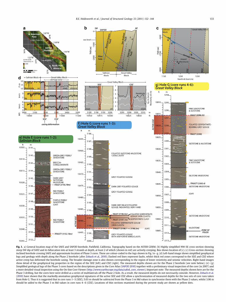
Fig. 1. a) General location map of the SAFZ and SAFOD borehole, Parkfield, California. Topography based on the ASTER GDEM. (b) Highly simplified NW-SE cross-section showingsteep SW dip of SAFZ and its bifurcation into at least 3 strands at depth, at least 2 of which (shown in red) are actively creeping. Box shows location of (c). (c) Cross-section showinginclined borehole crossing SAFZ and approximate location of Phase 3 cores. These are colour-coded to the logs shown in Fig. 1eeg. (d) Left-hand image shows simplified geophysicallogs and geology with depth along the Phase 2 borehole (after Zoback et al., 2010). Dashed red lines represent faults, whilst thick red zones correspond to the SDZ and CDZ whereactive creep has deformed the borehole casing. The broader damage zone is also shown corresponding to the region of lower resistivity and seismic velocities. Right-hand imagesshow detail of the geophysical log properties in the region of the SDZ (left) and CDZ (right). The measured depths shown are for the Phase 2 borehole (see note below). (e)e(g)Simplified geological logs of the Phase 3 cores based on the descriptions given in the Core Atlas (SAFOD 2010) together with a preliminary visual inspection of the core (in 2007) anda more detailed visual inspection using the On-line Core Viewer (http://www.earthscope.org/data/safod_core_viewer). Important note: The measured depths shown here are for thePhase 3 drilling, but the cores here were drilled as a series of multilaterals off the Phase 2 hole. As a result, the measured depths do not necessarily coincide. However, Zoback et al.(2010) have shown that the markedly anomalous geophysical signatures of the active SDZ and CDZ allow a synchronization of measured depths for the two sets of core runs takenfrom Hole G. Thus it is suggested that in core runs 1e3 (SDZ), 5.03 m should be subtracted from the Phase 3 m Md values to synchronise themwith the Phase 2 values, whilst 3.96 mshould be added to the Phase 3 m Md values in core runs 4e6 (CDZ). Locations of thin sections examined during the present study are shown as yellow dots.
R.E. Holdsworth et al. / Journal of Structural Geology 33 (2011) 132e144 133

R.E. Holdsworth et al. / Journal of Structural Geology 33 (2011) 132e144134
out by other geoscientists focussed on individual samples andshort sections of the core material.
2. SAFOD: geological setting and location of borehole
The San Andreas Fault forms the steeply dipping to sub-verticaldextral transcurrent boundary between the Pacific plate to thewestand the North American plate to the east (Fig. 1a and b). The faultzone is over 1000 km long, extends at depth to at least 15 km, and ismanifested at the surface by a complex zone of linked faults andassociated brittle deformation ranging from a few hundred metresto several kilometres wide (Allen, 1981). Geophysical data haverepeatedly demonstrated that the direction of maximumhorizontalstress in the crust lies at a high angle to the San Andreas Fault tractthroughout central California and remains at a high angle to within200 m of the active fault traces within the SAFOD boreholes (e.g.Hickman and Zoback, 2004; Zoback and Hickman, 2005; Bonessand Zoback, 2006). This evidence, together with the absence ofany measureable heat flow anomaly, either regionally or in any ofthe SAFOD boreholes (e.g. Sass et al., 1997; Williams et al., 2005)strongly suggests that active creep (at w2.5 cm/year; Titus et al.,2006) along the Parkfield segment of the San Andreas Fault(Fig. 1a) occurs at very low values of resolved shear stress.Following the drilling of the main SAFOD borehole, it becameapparent that two narrow (1e2 mwide) sections were undergoingactive deformation by creep due to localised fault movements at3192 m and 3302 m Md (¼ Measured depth, in this case along thelength of the Phase 2 borehole). Following Zoback et al. (2010),these active regions are referred to here as the southwest deformingzone (SDZ) and the central deforming zone (CDZ) (Fig. 1b and c).During the final stage of drilling, Phase 3, a series of multilateralswere cored off from and adjacent to the Phase 2 hole in order tosample the rocks lying close to the trace of the geological SanAndreas Fault and across the SDZ and CDZ (Fig. 1c).
In Central California, the San Andreas Fault separates rockslocated to thewest belonging to the Salinian block from rocks locatedto the east referred to here as theGreat Valley block, comprising unitsbelonging to both the highly deformed, subduction-related Fran-ciscan Complex and a Cretaceous forearc sedimentary sequenceknown as the Great Valley Group (Wakabayashi, 1999; Draper-Springer et al., 2009 and references therein). Close to the SAFZ atdepth, the NE-dipping Phase 2 borehole cuts a thick sequence ofarkosic sandstones and conglomerates inferred from detailedpetrological, zircon fission track analyses and regional geologicalstudies by Draper-Springer et al. (2009) to be of Paleocene-Eoceneage. At 3157mMd (as measured during Phase 2), an abrupt lithologychange occurs as the borehole passes into a sequence of fine grainedshales and siltstones (Bradbury et al., 2007), and at greater depths(below ca 3400 m Md) it passes into a siltstone-claystone sequencepreserving Late Cretaceous fossils consistent with these being rocksbelonging to the Great Valley Sequence (Draper-Springer et al.,2009). Most authors agree that the abrupt lithology change at3157 m Md marks the location of the presently inactive (non-creeping) ‘geological’ San Andreas Fault that forms the eastern limitof the Salinian Block. However, the protolith affinities of the shale-rich rocks located between 3157 m and (at least) 3400 m Md areless certain. They coincide with an approximately 240 m wideregion of low seismic velocities and resistivity interpreted to be the‘damage zone’ of the SAFZ (Fig. 1d, left-hand image; Zoback et al.,2010; Jeppson et al., 2010). Three localised (metre-wide) zoneslocated in the Phase 2 borehole at 3192 m (SDZ), 3302 m (CDZ) and3413 m (NDZ ¼ ‘Northeast deformed zone’) Md display even moremarkedly anomalous physical properties (Fig. 1d, right-hand image)and are thought to be active creeping and/or microseismicallyactive faults.
3. The Phase 3 core
Approximately 40 m of 10 cm diameter rock core was recoveredfrom ca 2.7 km vertical depth, sampling three key sections of thefault zone (Fig. 1c). The shallowest section of core comes from theSalinian Block (SB) wall rocks close to the trace of the geological SanAndreas Fault (Hole E, core runs 1 and 2, with a length of w11 m),whilst sections from the Great Valley Block (GVB) include the twoactively creeping fault segments (Hole G, core runs 1e3, w13 mlong, including the SDZ; and Hole G, core runs 4e6, w16 m long,including the CDZ) (SAFOD, 2010). The geological San Andreas Faultwas not cored due to operational difficulties during drilling (Zobackpers. comm. 2007). Simplified summary logs of these three rela-tively continuous sections of core are presented in Fig. 1eeg. Notethat as explained in the figure caption, the measured depths foreach of the Phase 3 cores differ slightly from those recorded duringPhase 2.
The lithological subdivision of the Phase 3 cores provides thegeological and spatial context for the microstructural observationsmade from the 38 thin sections (for location see yellow dots inFig. 1eeg) that form the main part of the paper. The cores can bemost conveniently divided into three domain types:
1) Relatively undeformed host rocks (Fig. 2aeb; all of the corefrom Hole E [SB], most of the core from the deeper part of HoleG (part of core run 4, all of core runs 5e6 [GVB]);
2) Pervasively sheared regions of presently ‘inactive’ (not creeping)fault rocks (Fig. 2cee; parts of core run 2 and of all core runs 1and 3, Hole G [GVB]);
3) Narrow, pervasively sheared regions of actively creeping faultrocks, the SDZ (lower part of core run 2, Hole G, Fig. 2f) and theCDZ (part of core run 4, Hole G).
The SDZ and CDZ in the core are both bounded by brittle faults.The other domain boundaries are not sampled by the existingcore sections. Finally, it should be noted that the thin sectionsstudied here were generally not oriented relative to the core, soit has not been possible to reconstruct either the directions ofyounging (e.g. Fig. 2b) or shear sense (e.g. Fig. 2c) observed inmany samples.
3.1. Host rock domains: lithologies, mesostructure andmicrostructure
The Salinian block rocks sampled in core runs 1 and 2, Hole E, lieclose to the projected trace of the geological San Andreas Fault atdepth. The core materials comprise a sequence of green-grey,purple and red pebbly arkosic sandstones, together with a prom-inent, 1 m thick unit of dark grey siltstone-mudstone bounded at itsbase by a well defined fault (Fig. 1e). Bedding, defined by grainsizeand compositional variations, iron oxide staining and by a crudealignment of pebble clasts, lies in a range of orientations relative tothe axis of the core. Bedding laminations are offset by networks ofminor faults arranged in a wide variety of orientations that carrydark red-brown, iron-stained zones of cataclasite up to 1 cm thick.
In thin section, the sandstones are predominantly (85e95%)composed of K-feldspar, plagioclase, and quartz, with subordinategrains of mica, ore, epidote and sphene, together with variable, butgenerally small (5e15%), amounts of illitic clay-rich matrix. Thesandstone conglomerates are typically clast-supported, coarse tovery coarse grained, with subrounded to subangular grain shapesand abundant pebble clasts (mainly feldspathic) locally up to 3 cmacross (Fig. 2a). Individual sedimentary clasts are derived primarilyfromweakly deformed granitic protoliths as they preserve primaryigneous textures and deformation features such as myrmekites and

Fig. 2. Optical micrographs of typical host rock and fault zone rocks (with mMd given in metres) from the Phase 3 cores, all in plane polarised light. (a) Typical example of a coarse-grained arkosic sandstone that dominates the Salinian Block lithologies. Grain-scale microfracturing and minor faulting are widespread (e.g. Fig. 3a), but pervasive deformation isgenerally absent. (b) Laminated siltstone-mudstone host rock typical of the found in the Great Valley Block. Primary structures such as graded bedding (G), bioturbation (B), cross-lamination (CL) and convolute bedding (CB) give way up (see younging arrow). Microfossils (e.g. inset, with longest dimension of 200 mm) and carbonaceous materials arewidespread. (c)e(e) Features of fault gouges in the inactive parts of the SAFZ from core runs 1e3, Hole G. (c) Mechanical shredding by folding and the development of Riedel-typeshears deforming gouge materials derived from mudstones (brown) and subordinate sandstone lenses (pale). The mechanical comminution leads to the development of dark-brown-black gouge forming and interlinked network. Note that the sense of shear indicated by the Riedel shears and the folds are consistent throughout the thin section. (d) Blackgouge similar to those seen in (c) hosted in fractures cutting a mudstone clast (?) e such features suggest that the gouges must have locally become fluidised and injected,presumably during periodic overpressuring events. (e) Clast of light brown mudstone enclosed within darker uniform gouge which is itself enclosed as a clast within a still darkerfoliated gouge. This sample comes from just outside the actively creeping region in core run 3, Hole G. Such features suggest multiple phases of shearing and gouge formation. Theveins comprise intergrown fibrous calcite and anhydrite and are likely indicative of fluid-pressure-induced tensile fracturing events. They cut the two earlier gouges and are foundas clasts in the youngest gouge. (f) Foliated gouge with clasts of sandstone (Sst) and serpentinite (Serp) from the active SDZ in core run 2, Hole G.
R.E. Holdsworth et al. / Journal of Structural Geology 33 (2011) 132e144 135
dynamic recrystallization of quartz. The siltstoneemudstone unitpreserves fine-grained clay-rich matrix (95%) with isolated clasts ofquartz, feldspar and chlorite (after biotite?).
Individual feldspar grains in sandstones are often weakly frac-tured, possibly due to the effects of tectonic compaction, but for themost part the sedimentary rocks lack pervasive deformation. Inthe sandstones, minor faults mostly display narrow (<mm-wide)zones of cataclasite, with local pressure solution seams (e.g.Fig. 3a). These give way in the lower part of the core from Hole E tobroader (cm wide) diffuse zones of crushing, irregularly veinedwith calcite and ore; fibrous phyllosilicate (illite-smectite) alsoforms a minor, texturally early vein fill. Fluid-related alterationpreferentially affects plagioclase grains which display highlysutured, curvilinear grain boundaries and internal alteration
patches that host the growth of fine grained, irregular aggregatesof phyllosilicate (illite-smectite). Aligned, fine- to ultrafine-grainedaggregates (with individual grain basal lengths of mainly<1 mm) ofsmectitic phyllosilicate define the isolated solution seamspreserved in fault-related sandstone-derived cataclasites and formmuch more extensive interconnected networks (up to 30 mm thick)in siltstoneemudstone host rocks (e.g. Fig. 4a). Here, BSE images(e.g. Fig. 4a inset) show that the strongly aligned smectitic phases(mainly illite-smectite based on EDX analyses, Fig. 5a) are prefer-entially developed along fracture surfaces, forming by theprogressive replacement of existing matrix grains of phyllosilicate,as well as forming new fibrous overgrowths around host rockclasts. Host rock clasts of quartz and feldspar are noticeably rare inthese aligned networks of phyllosilicate and are often sharply

Fig. 3. Illustrative examples of textures consistent with the operation of stress-induced solution-precipitation and diffusive mass transfer processes in the SAFOD fault rocks (withMd given in metres). (a)e(d) are optical images in polarised light. (e) is a BSE image from the SEM. (a) Discontinuous, dark pressure solution seams (labelled ‘P’) associated with
R.E. Holdsworth et al. / Journal of Structural Geology 33 (2011) 132e144136
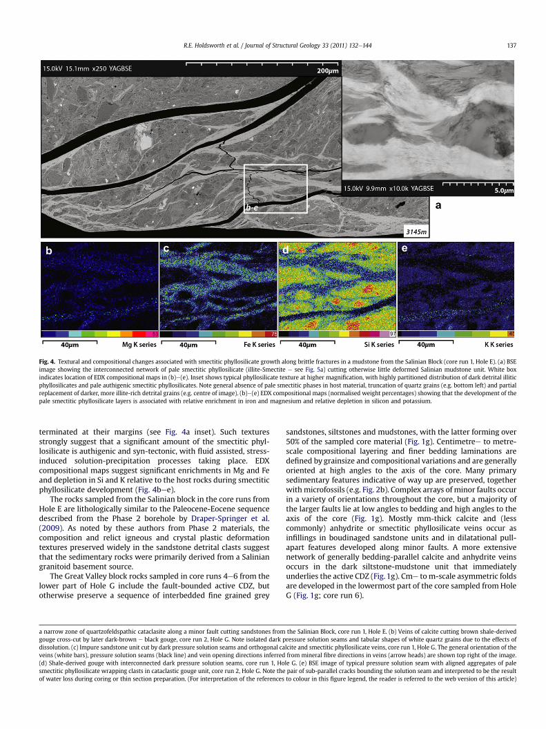
Fig. 4. Textural and compositional changes associated with smectitic phyllosilicate growth along brittle fractures in a mudstone from the Salinian Block (core run 1, Hole E). (a) BSEimage showing the interconnected network of pale smectitic phyllosilicate (illite-Smectite e see Fig. 5a) cutting otherwise little deformed Salinian mudstone unit. White boxindicates location of EDX compositional maps in (b)e(e). Inset shows typical phyllosilicate texture at higher magnification, with highly partitioned distribution of dark detrital illiticphyllosilicates and pale authigenic smectitic phyllosilicates. Note general absence of pale smectitic phases in host material, truncation of quartz grains (e.g. bottom left) and partialreplacement of darker, more illite-rich detrital grains (e.g. centre of image). (b)e(e) EDX compositional maps (normalised weight percentages) showing that the development of thepale smectitic phyllosilicate layers is associated with relative enrichment in iron and magnesium and relative depletion in silicon and potassium.
R.E. Holdsworth et al. / Journal of Structural Geology 33 (2011) 132e144 137
terminated at their margins (see Fig. 4a inset). Such texturesstrongly suggest that a significant amount of the smectitic phyl-losilicate is authigenic and syn-tectonic, with fluid assisted, stress-induced solution-precipitation processes taking place. EDXcompositional maps suggest significant enrichments in Mg and Feand depletion in Si and K relative to the host rocks during smectiticphyllosilicate development (Fig. 4bee).
The rocks sampled from the Salinian block in the core runs fromHole E are lithologically similar to the Paleocene-Eocene sequencedescribed from the Phase 2 borehole by Draper-Springer et al.(2009). As noted by these authors from Phase 2 materials, thecomposition and relict igneous and crystal plastic deformationtextures preserved widely in the sandstone detrital clasts suggestthat the sedimentary rocks were primarily derived from a Saliniangranitoid basement source.
The Great Valley block rocks sampled in core runs 4e6 from thelower part of Hole G include the fault-bounded active CDZ, butotherwise preserve a sequence of interbedded fine grained grey
a narrow zone of quartzofeldspathic cataclasite along a minor fault cutting sandstones fromgouge cross-cut by later dark-brown e black gouge, core run 2, Hole G. Note isolated dark pdissolution. (c) Impure sandstone unit cut by dark pressure solution seams and orthogonal caveins (white bars), pressure solution seams (black line) and vein opening directions inferred(d) Shale-derived gouge with interconnected dark pressure solution seams, core run 1, Hosmectitic phyllosilicate wrapping clasts in cataclastic gouge unit, core run 2, Hole G. Note theof water loss during coring or thin section preparation. (For interpretation of the references
sandstones, siltstones and mudstones, with the latter forming over50% of the sampled core material (Fig. 1g). Centimetree to metre-scale compositional layering and finer bedding laminations aredefined by grainsize and compositional variations and are generallyoriented at high angles to the axis of the core. Many primarysedimentary features indicative of way up are preserved, togetherwithmicrofossils (e.g. Fig. 2b). Complex arrays of minor faults occurin a variety of orientations throughout the core, but a majority ofthe larger faults lie at low angles to bedding and high angles to theaxis of the core (Fig. 1g). Mostly mm-thick calcite and (lesscommonly) anhydrite or smectitic phyllosilicate veins occur asinfillings in boudinaged sandstone units and in dilatational pull-apart features developed along minor faults. A more extensivenetwork of generally bedding-parallel calcite and anhydrite veinsoccurs in the dark siltstone-mudstone unit that immediatelyunderlies the active CDZ (Fig. 1g). Cme to m-scale asymmetric foldsare developed in the lowermost part of the core sampled fromHoleG (Fig. 1g; core run 6).
the Salinian Block, core run 1, Hole E. (b) Veins of calcite cutting brown shale-derivedressure solution seams and tabular shapes of white quartz grains due to the effects oflcite and smectitic phyllosilicate veins, core run 1, Hole G. The general orientation of thefrom mineral fibre directions in veins (arrow heads) are shown top right of the image.le G. (e) BSE image of typical pressure solution seam with aligned aggregates of palepair of sub-parallel cracks bounding the solution seam and interpreted to be the resultto colour in this figure legend, the reader is referred to the web version of this article)
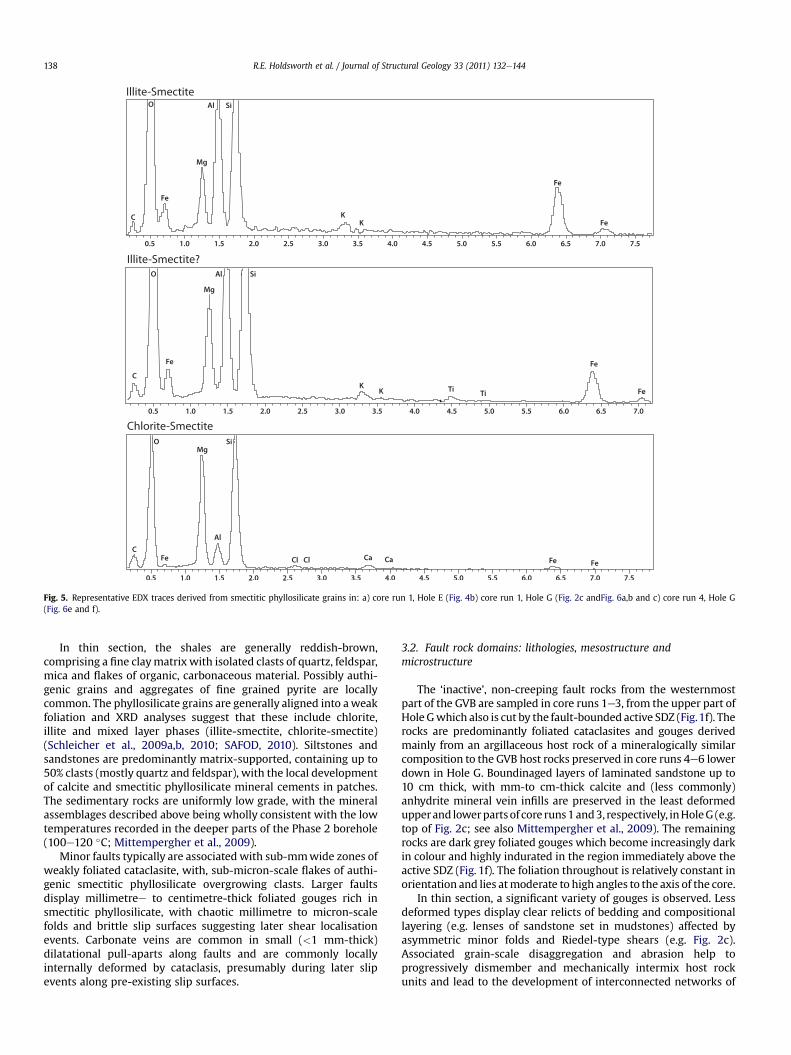
Fig. 5. Representative EDX traces derived from smectitic phyllosilicate grains in: a) core run 1, Hole E (Fig. 4b) core run 1, Hole G (Fig. 2c andFig. 6a,b and c) core run 4, Hole G(Fig. 6e and f).
R.E. Holdsworth et al. / Journal of Structural Geology 33 (2011) 132e144138
In thin section, the shales are generally reddish-brown,comprising a fine claymatrix with isolated clasts of quartz, feldspar,mica and flakes of organic, carbonaceous material. Possibly authi-genic grains and aggregates of fine grained pyrite are locallycommon. The phyllosilicate grains are generally aligned into aweakfoliation and XRD analyses suggest that these include chlorite,illite and mixed layer phases (illite-smectite, chlorite-smectite)(Schleicher et al., 2009a,b, 2010; SAFOD, 2010). Siltstones andsandstones are predominantly matrix-supported, containing up to50% clasts (mostly quartz and feldspar), with the local developmentof calcite and smectitic phyllosilicate mineral cements in patches.The sedimentary rocks are uniformly low grade, with the mineralassemblages described above being wholly consistent with the lowtemperatures recorded in the deeper parts of the Phase 2 borehole(100e120 �C; Mittempergher et al., 2009).
Minor faults typically are associated with sub-mmwide zones ofweakly foliated cataclasite, with, sub-micron-scale flakes of authi-genic smectitic phyllosilicate overgrowing clasts. Larger faultsdisplay millimetree to centimetre-thick foliated gouges rich insmectitic phyllosilicate, with chaotic millimetre to micron-scalefolds and brittle slip surfaces suggesting later shear localisationevents. Carbonate veins are common in small (<1 mm-thick)dilatational pull-aparts along faults and are commonly locallyinternally deformed by cataclasis, presumably during later slipevents along pre-existing slip surfaces.
3.2. Fault rock domains: lithologies, mesostructure andmicrostructure
The ‘inactive’, non-creeping fault rocks from the westernmostpart of the GVB are sampled in core runs 1e3, from the upper part ofHoleGwhich also is cut by the fault-bounded active SDZ (Fig.1f). Therocks are predominantly foliated cataclasites and gouges derivedmainly from an argillaceous host rock of a mineralogically similarcomposition to the GVB host rocks preserved in core runs 4e6 lowerdown in Hole G. Boundinaged layers of laminated sandstone up to10 cm thick, with mm-to cm-thick calcite and (less commonly)anhydrite mineral vein infills are preserved in the least deformedupperand lowerpartsof core runs1and3, respectively, inHoleG (e.g.top of Fig. 2c; see also Mittempergher et al., 2009). The remainingrocks are dark grey foliated gouges which become increasingly darkin colour and highly indurated in the region immediately above theactive SDZ (Fig. 1f). The foliation throughout is relatively constant inorientation and lies atmoderate to high angles to the axis of the core.
In thin section, a significant variety of gouges is observed. Lessdeformed types display clear relicts of bedding and compositionallayering (e.g. lenses of sandstone set in mudstones) affected byasymmetric minor folds and Riedel-type shears (e.g. Fig. 2c).Associated grain-scale disaggregation and abrasion help toprogressively dismember and mechanically intermix host rockunits and lead to the development of interconnected networks of
R.E. Holdsworth et al. / Journal of Structural Geology 33 (2011) 132e144 139
dark-brown black gouge (e.g. Fig. 2c). Compositionally similar unitsof black gouge are seen to locally infill irregular fracture networkscutting more intact regions of shale (e.g. Fig. 2d) and appear to havebeen injected, presumably under enhanced fluid pressures. Sub-mm to cm-scale networks of mainly calcite and subordinateanhydrite veins are preserved that formed prior to, during and afterlocal gouge forming events (e.g. Fig. 3b). More evolved gouges canappear rather more texturally homogeneous on first inspection, butthe localised preservation of clasts within clasts (e.g. Fig. 2e) pointsto a protracted history of multiple brecciation and re-brecciation.
There is widespread textural evidence for the operation of grain-scale fluid-assisted diffusive mass transfer processes. Dark pressuresolution seams are preserved in both sandstones and shales (Fig. 3cand d, respectively), and in the former lithology, are associatedwithcalcite veins filling intergranular fractures oriented orthogonally tothepressure-solution seams (Fig. 3c). The solution seamsaredefinedby the growth of aligned, fibrous aggregates of ultrafine-grainedsmectitic phyllosilicates that wrap around pre-existing clasts(Fig. 3e). Thedevelopmentof thebrown-blackgougesbycataclasis isalso intimately associated with a volumetrically more pervasivegrowth of fine- to ultrafine-grained interconnected networks ofsmectitic phyllosilicate (Fig. 6a and b;mainly FeeMg illite-smectite,Fig. 5b). These observations demonstrate that during gouge devel-opment, stress-induced solution-precipitation creep processes areclosely associated with cataclasis and grain-scale fluid pressure-induced fracturing, as speculated by Schleicher et al. (2009b, 2010).Many of the inactive, non-creeping fault gougese and especially theblackest types e are additionally characterised by the widespreadgrowth of fine disseminated grains of relatively late-stage authi-genic pyrite (e.g. Figs 3e,6aec).
The active creeping fault rocks sampled in core runs 2 and 4,Hole G, are 1e2 mwide, fault-bounded units that are quite distinctfrom the other fault rocks on both lithological and textural grounds.The rocks are dark grey-green foliated gouges with a highlydistinctive scaly fabric with numerous polished and striated folia-tion surfaces (e.g. SAFOD, 2010). They contain a wide variety ofrounded clasts, some up to several tens of cm across, most parti-cularly of green serpentinite cut by numerous calcite veins, a clasttype not found out with of the active shear zones (Figs. 1f and g, 2f).Other clast types include sandstones, siltstones and mudstonessimilar to the adjacent GVB lithologies, crystalline carbonate andsome possible granitic units. In sharp contrast to the inactivegouges, where mineral veins are intergranular and continuous, inactive gouges mineral veins only occur as individual clasts or insideclasts of other lithologies, including serpentinite. Sills et al. (2009)have used X-ray Computed Tomography imaging to investigate themesoscale structure of the active gouge core samples. They haveshown that the clasts in the gouge have a strong shape preferredorientation, with long axes oriented sub-parallel to the SAFZ andthat the observed uniformity in porphyroclast shapes and sizes isconsistent with distributed deformation during aseismic creep.
In optically imaged thin sections and under the SEM, samples ofthese foliated gouge units are particularly distinct due to thewidespread development of foliation-parallel, curviplanar inter-linked networks of micron-scale cracks (e.g. the black features seenin the SEM images shown in Fig. 6d and e), features likely formedfollowing coring and possibly during thin section preparation (seebelow). The foliation is typically phacoidal, with asymmetrictextures (shear bands, sigma-porphyroclasts) and often dishar-monic folds on centimetre to micron-scales (e.g. Fig. 6e and f). Thegougematrix is completely dominated by the development of fineeto ultrafine-grained aligned aggregates of Mg-rich smectitic phyl-losilicate (chlorite-smectites, possibly corrensite and/or saponite,Fig. 5c; see also SAFOD, 2010) which now forms over 50% ofthe total rock volume. Locally, the development of multiple
generations of smectitic phyllosilicate is evident from the breccia-tion of earlier grains and their overgrowth by new fibrous grainssuggesting cyclic alternations in solution-precipitation creepprocesses and cataclasis.
Given the widespread presence of smectitic phases in theactive gouges, it is suggested that the curviplanar crack networkslikely reflect dewatering and volume loss in the clays during coresampling and thin section preparation. The rocks tend to breakalong these surfaces which display the characteristic polishedand striated appearance. Contrary to the views expressed bysome authors (e.g. Schleicher et al., 2010), there is nothingparticularly unusual about the presence of such features in rocksof this composition. Analogous features are seen, for example,along shear fractures developed in smectite-rich clay soilsformed due to seasonally controlled swelling and shrinkingbehaviour (Van Breemen and Buurman, 2002). Similar, but lessintensely developed cracks are also associated with smectiticphyllosilicate-rich rocks in both the inactive gouges and alongsome minor faults cutting host rock units (e.g. see Figs. 3e and 4a,respectively).
The textural and mineralogical differences between the inactiveand active gouge domains are strikingly emphasised by the resultsof EDX compositional mapping (Fig. 7). The active gouges aremarkedly enriched in Mg and depleted in Si compared to theimmediately adjacent unit of inactive gouge that is located less thanhalf a metre away. Relative enrichments in iron and depletion inpotassium (as seen in smectite-rich gouges in the inactivesegments, e.g. Fig. 4c and e) are not observed in the activelycreeping gouges. Further detailed X-ray diffraction analyses, TEMand microprobe analyses are clearly required in order to properlycharacterise the mineralogy and compositional distribution of thesmectitic phyllosilicate phases present within both inactive andactive fault gouges from the Phase 3 SAFOD core.
4. Discussion
In the absence of a comprehensive microstructural, microana-lytical and geochronological study of all of the Phase 3 SAFOD corematerials, it is important to recognise that at present, only defor-mation features seen in the actively creeping shear zones can beattributed to SAFZ movements with reasonable certainty. Theresults of 40Ar/39Ar dating of illites in SAFOD samples carried outby Schleicher et al. (2010) have yielded Miocene (8 � 1.3 Ma) toPliocene (4 � 4.9) ages consistent with earlier phases of faultmovement. Nevertheless, it is still conceivable that some of thedeformation features seen in the host rocks and inactive, non-creeping gouges may entirely pre-date the development of theSAFZ, particularly if deformed rocks derived from the subduction-related melanges of the Franciscan Formation are entrained withinthe fault zone (e.g. Evans et al., 2009; Bradbury and Evans, 2009). Inour opinion, the observed textural and mineralogical continuity ofthe GVB host rocks and gouges argues against such a possibility, asdoes the absence of relict high pressure metamorphic mineralssuch as jadeite, pumpellyite or glaucophane which typify rocks ofthe Franciscan Formation (e.g. Bailey et al., 1964; Ernst, 1973). In thefollowing discussion, we will therefore assume that all the defor-mational andmineralogical processes observed in all the fault rocksare related to fault movements during the history of the SAFZ.
Previous studies carried out during Phases 1 and 2 of the SAFODdrilling have shown that high pore fluid pressures are not currentlydeveloped in the fault zone (e.g. Zoback et al., 2010), whilst Heliumgas isotopic analyses from within the borehole reveal significantdifferences in the 3He/4He ratios either side of the fault core sug-gesting that it acts as a regional fluid seal (Wiersberg and Erzinger,2008). This seems consistent with the observed clay-rich nature of
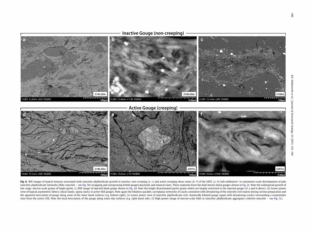
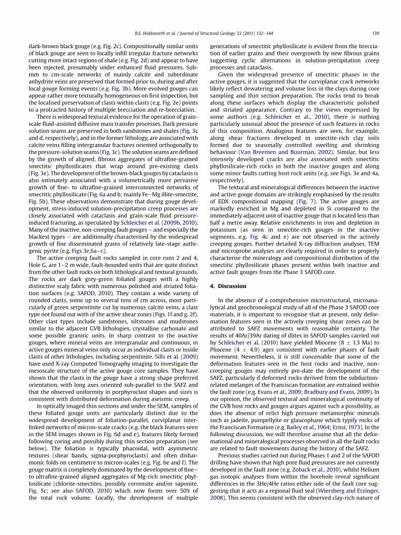
Fig. 6. BSE images of typical textures associated with smectitic phyllosilicate growth in inactive, non-creeping (aec) and active creeping shear zones (def) of the SAFZ. (aeb) Sub-millimetre- to nanometre-scale development of palesmectitic phyllosilicate networks (illite-smectite e see Fig. 5b) wrapping and overgrowing brittle gouge/cataclasite and mineral clasts. These materials form the dark-brown-black gouges shown in Fig. 2c. Note the widespread growth oflate stage, micron-scale grains of bright pyrite. (c) BSE image of injected black gouge shown in Fig. 2d. Note the bright disseminated pyrite grains which are largely restricted to the injected gouge (cf. a and b above). (d) Lower powerview of typical asymmetric fabrics (shear bands, sigma clasts) in active SDZ gouges. Note again the foliation-parallel, curviplanar networks of cracks consistent with dewatering of the smectite-rich matrix during section preparation andthe apparent brecciation of gouge along some of the shear band surfaces (e.g. bottom right). (e) Lower power view of smectitic phyllosilicate-rich, chaotically foliated gouge (again with dewatering cracks) surrounding a serpentiniteclast from the active CDZ. Note the local brecciation of the gouge along some slip surfaces (e.g. right-hand side). (f) High power image of micron-scale folds in smectitic phyllosilicate aggregates (chlorite-smectite e see Fig. 5c).
R.E.Holdsw
orthet
al./Journal
ofStructural
Geology
33(2011)
132e144
140
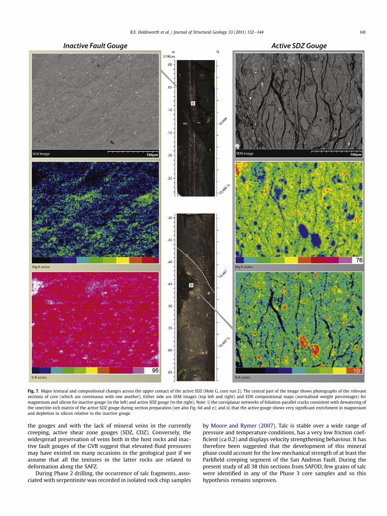
Fig. 7. Major textural and compositional changes across the upper contact of the active SDZ (Hole G, core run 2). The central part of the image shows photographs of the relevantsections of core (which are continuous with one another). Either side are SEM images (top left and right) and EDX compositional maps (normalised weight percentages) formagnesium and silicon for inactive gouge (to the left) and active SDZ gouge (to the right). Note: i) the curviplanar networks of foliation-parallel cracks consistent with dewatering ofthe smectite-rich matrix of the active SDZ gouge during section preparation (see also Fig. 6d and e); and ii) that the active gouge shows very significant enrichment in magnesiumand depletion in silicon relative to the inactive gouge.
R.E. Holdsworth et al. / Journal of Structural Geology 33 (2011) 132e144 141
the gouges and with the lack of mineral veins in the currentlycreeping, active shear zone gouges (SDZ, CDZ). Conversely, thewidespread preservation of veins both in the host rocks and inac-tive fault gouges of the GVB suggest that elevated fluid pressuresmay have existed on many occasions in the geological past if weassume that all the textures in the latter rocks are related todeformation along the SAFZ.
During Phase 2 drilling, the occurrence of talc fragments, asso-ciated with serpentinite was recorded in isolated rock chip samples
by Moore and Rymer (2007). Talc is stable over a wide range ofpressure and temperature conditions, has a very low friction coef-ficient (ca 0.2) and displays velocity strengthening behaviour. It hastherefore been suggested that the development of this mineralphase could account for the lowmechanical strength of at least theParkfield creeping segment of the San Andreas Fault. During thepresent study of all 38 thin sections from SAFOD, few grains of talcwere identified in any of the Phase 3 core samples and so thishypothesis remains unproven.

R.E. Holdsworth et al. / Journal of Structural Geology 33 (2011) 132e144142
A range of other, potentially weak minerals were identified inrock chippings recovered during the Phase 2 drilling, including illiteand chlorite, together with illite-smectite and chlorite-smectitemixed layer clays, including possibly both corrensite and saponite(e.g. Solum et al., 2006; Schleicher et al., 2009a,b 2010; SAFOD,2010). The mixed layer smectitic phases are particularly signifi-cant as numerous experimental studies have shown that thepresence of such hydrous mineral phases can substantially reducethe shear strength of rocks (e.g. Wang, 1984; Saffer et al., 2001;Saffer and Marone, 2003; Morrow et al., 2007).
Based on analyses of fault rock chips recovered during drillingand coring, Schleicher et al. (2006, 2010) refer to the presence anddevelopment of thin so-called ‘nanocoatings’ of smectite along slipsurfaces. Our analysis of the thin sections taken from the intact core(e.g. Fig. 5aef) demonstrates that the development of smectiticphyllosilicates is far more widespread than is implied by theseauthors and that in the actively creeping gouges, they form thedominantmatrix minerals. Deformation experiments carried out onpowdered samples rich in these minerals consistently showreduced friction coefficients, in some cases as low as 0.3 (Tembeet al., 2006; Morrow et al., 2007; Carpenter et al., 2009). Theobserved pervasive development of interconnected networks ofstrongly aligned phyllosilicate phases is particularly important asthis can significantly enhance the upscale transfer of grain-scaleweakening effects (Wintsch et al., 1995; Holdsworth, 2004). Inlaboratory-based deformation studies carried out in talc-rich faultrocks, Collettini et al. (2010) have shown that experiments carriedout on intact fault rock wafers, where the interconnected networkof weak phyllosilicates is preserved, yield significantly lower fric-tion coefficients compared to powdered samples of the same faultrocks. On this basis, it is reasonable to propose that futuremeasurements of friction carried out on intact rock wafers of thesmectite-rich SAFZ fault gouges will probably yield friction coeffi-cients lower than 0.2, the value predicted by existing stress andheat flow data (e.g. Moore and Rymer, 2007). The apparent weak-ness of the SAFZ gouges is more generally attested to by theobservation that deformation e including the current creepdisplacements e has clearly localised into the relatively narrowregions of gouge that contain the highest proportions of smectiticphyllosilicates, especially Mg-rich varieties.
Theobserved textural relationships andcompositionalmaps (e.g.Figs. 3e7), together with the geochemical studies of Schleicher et al.(2009a,b) suggest that the development of the phyllosilicate-richfault rocks is associated with the widespread operation of stress-induced solution-precipitation and mass transfer processes. Thismakes it possible that processes other than frictional sliding (sensustricto) have contributed to fault weakening and creep along theSAFZ. There is abundant evidence fromtheoretical andexperimentalstudies (e.g. Mares and Kronenberg, 1993; Bos and Spiers, 2000,2002; Bos et al., 2000a,b; Niemeijer and Spiers, 2005; Jefferieset al., 2006b) that the onset of diffusive mass transfer mechanismsin phyllosilicate-rich fault rocks can lead to profound weakening infault zones. The closely associated processes of cataclasis and thegrowth of finee to ultrafine-grained aggregates of authigenic phyl-losilicates in the gouges will help to facilitate the operation ofgrainsize-sensitive diffusive mass transfer mechanisms at strainrates that will make a significant contribution to the active creep of2.5 cm/year observed along the Parkfield segment of the SAFZ.
Recent geological studies of the exhumed deeper parts of oldcrustal-scale structures elsewhere in the world, such as repeatedlyreactivated faults and low angle normal faults, suggest that weak-ening in narrow fault cores is also related to the development offoliated, phyllosilicate-rich fault rocks following cataclasis (e.g.Wintsch et al., 1995; Imber et al., 1997; Gueydan et al., 2003;Collettini and Holdsworth, 2004; Jefferies et al., 2006a,b). In
several examples, the growth of Mg-rich phyllosilicates can bedirectly related to weakening (e.g. Mg-chlorite in the MTL, Japan,Jefferies et al., 2006a; talc in the Zuccale Fault, Italy, Collettini et al.,2009, 2010). This suggests that the processes recognised along theSAFZ in the SAFOD borehole are of direct relevance to a moregeneral understanding of weakening in all crustal-scale fault zones.
5. Conclusions
Based on our microstructural study of 38 thin sections from thePhase 3 SAFOD core, we conclude that the SAFZ preserves a suite offault rocks showing evidence for the operation of upper crustalfluid-related fault weakening and chemical alteration processes.Minor faults cutting the host rocks display classical brittle defor-mation processes involving repeated cycles of cataclasis, pressuresolution and fluid pressure-induced fracturing. The resultingmineral veins (calcite, anhydrite) formed prior to, during and afterlocal fault rock-forming deformation episodes.
The ‘signature’ fault zone process in the larger displacementfaults associated with the SAFZ is the development of foliatedcataclasites and gouges comprising interconnected networks of lowfriction smectitic phyllosilicates (m likely <0.3). Talc is largelyabsent in the thin sections examined during the present study.Outwith of the actively creeping shear zones, the smectite-enrichment is most likely related to fluiderock interactions, withmarked enrichments in Mg, Fe and depletions in Si and K observed.Along more minor faults in host rocks, there is a strong composi-tional control on the intensity of smectitic phyllosilicate develop-ment, but alteration becomes more widespread in largerdisplacement fault gouges. The development of smectitic phyllo-silicate becomes ubiquitous in the actively deforming serpentiniteclast-bearing gouges. Here the chemical alteration associated withsmectite growth is significantly different, displaying amoremarkedenrichment in Mg and depletion in Si compared to the adjacentinactive gouges. The enrichment in disseminated pyrite observed inthe wall rocks immediately above the SDZ in core run 2, Hole G(Fig. 1f) may also indicate some loss in Fe from the actively creepingshear zones. The close spatial association between the presence ofserpentinite clasts and the ubiquitous growth of markedly Mg-richsmectites may indicate a genetic link between these two features.Speculatively, the weakening required in order to develop theactively creeping shear zones may have been triggered by a rela-tively recent influx of Mg-rich fluids that have interacted with theserpentinite bodies entrained within the SAFZ (cf. Moore andRymer, 2007). The lack of mineral veins in the gouge matrix ofthe shear zones implies that any such influx was localised, gradualand was not obviously facilitated by the widespread developmentof fluid-induced fracture systems.
It is important to end with a note of caution: the developmentof smectitic phyllosilicate-rich fault rocks on its own does notprovide an explanation for the overall weakness of crustal-scalefaults such as the SAFZ which extend down to depths of 15 km ormore. It is generally agreed that smectitic low friction clays such assaponite will break down at temperatures not much greater thanthose encountered close to the bottom of the SAFOD borehole (ca.100e120 �C) where they are likely to be replaced by minerals withhigher friction coefficients, e.g. Mg-chlorite (Frey and Robinson,1999). Thus the development of such clays only representsa plausible weakening mechanism for faults in the uppermost partof the crust (0e5 km depth). At greater depths and highertemperatures, other processes, such as stress-induced solution-precipitation creep may become more important leading to so-called ‘frictional-viscous flow’ (e.g. Bos and Spiers, 2000,2002;Jefferies et al., 2006a,b). More generally, geological studies ofcrustal-scale weak faults have shown that the growth of

R.E. Holdsworth et al. / Journal of Structural Geology 33 (2011) 132e144 143
interconnected networks of weak phyllosilicates reflectsa complex and protracted interaction between fluid-assisteddeformation processes such as hydrofracture, cataclasis, stress-induced solution-precipitation and frictional sliding. Each maylead to weakening effects operating on different timescales, but itis their combination that ultimately leads to the development offaults that are weak in an absolute sense.
Acknowledgements
The authors would particularly like to thank the following fortheir help and discussions during the preparation of this paper: JimEvans, Kelly Bradbury, Anja Schleicher, Steve Smith, André Nie-meijer, Silvia Mittempergher, Mark Zoback, and Chris Marone.Steve Hickman is due special thanks for numerous discussions andhelp that go well beyond what might reasonably be expected. Weare also grateful for the constructive and informative reviewsprovided by Diane Moore and an anonymous reviewer, togetherwith the editorial guidance of Cees Passchier. The views expressedhere are, however, entirely the responsibility of the authors. REHgratefully acknowledges the receipt of a Leverhulme ResearchFellowship during the preparation of this paper.
References
Allen, C.R., 1981. The modern San Andreas fault. A Symposium in Honour of, In:Rubey, W.W., Ernst, W.G. (Eds.), The Geotectonic Development of California.Prentice Hall, Englewood Cliffs, New Jersey, pp. 511e534.
Bailey, E.H., Irwin, W.P., Jones, D.L., 1964. Franciscan and related rocks, and theirsignificance in the geology of western California. California Division of MinesGeological Bulletin 183, 171.
Boness, N.L., Zoback, M.D., 2006. A multi-scale study of the mechanisms controllingshear velocity anisotropy in the San Andreas Fault Observatory at depth.Geophysics 7 (5), F131eF146.
Bos, B., Peach, C.J., Spiers, C.J., 2000a. Frictional-viscous flow of simulated faultgouge caused by the combined effects of phyllosilicates and pressure solution.Tectonophysics 327, 173e194.
Bos, B., Peach, C.J., Spiers, C.J., 2000b. Slip behaviour of simulated gouge-bearingfaults under conditions favoring pressure solution. Journal of GeophysicalResearch 105, 16699e16717.
Bos, B., Spiers, C.J., 2000. Effect of phyllosilicates on fluid-assisted healing of gouge-bearing faults. Earth and Planetary Science Letters 184, 199e210.
Bos, B., Spiers, C.J., 2002. Frictional-viscous flow of phyllosilicate-bearing fault rock:microphysical model and implications for crustal strength profiles. Journal ofGeophysical Research 107, 2028. doi:10.1029/2001JB000301.
Bradbury, K.K., Barton, D.C., Solum, J.G., Draper, S.D., Evans, J.P., 2007. Mineralogic andtextural analyses of drill cuttings from the San Andreas Fault Observatory at Depth(SAFOD)boreholes: initial interpretationsof fault zonecompositionandconstraintson geologic models. Geosphere 3 (5), 299e318. doi:10.1130/GES00076.1.
Bradbury, K.K., Evans, J.P., 2009. Franciscan formation within the SAFOD borehole,near Parkfield, CA. In: Geological Society of America, Abstracts and Programs,vol. 41, p. 404.
Brune, J.N., Henyey, T.L., Roy, R.F., 1969. Heat flow, stress, and rate of slip along theSan Andreas fault, California. Journal of Geophysical Research 74, 3821e3827.
Carpenter, B.M., Marone, C., Saffer, D.M., 2009. Frictional behavior of materials inthe 3D SAFOD volume. Geophysical Research Letters 36. doi:10.1029/2008GL036660.
Collettini, C., Holdsworth, R.E., 2004. Fault zone weakening and character of slipalong low-angle normal faults: insights from the Zuccale fault, Isle of Elba, Italy.Journal of the Geological Society of London 161, 1039e1051.
Collettini, C., Niemeijer, A.R., Viti, C., Marone, C., 2009. Fault zone fabric and faultweakness. Nature 462, 907e910.
Collettini, C., Niemeijer, A.R., Viti, C., Marone, C., 2010. Mechanical behaviour ofphyllosilicate-rich faults. Geophysical Research Abstracts 12 (EGU 2010e10139).
Draper-Springer, S., Evans, J.P., Garver, J.I., Kirschner, D., Janecke, S.U., 2009. Arkosicrocks from the San Andreas fault Observatory at depth (SAFOD) borehole,central California; implications for the structure and tectonics of the SanAndreas fault zone. Lithosphere 1, 206e226.
Ernst, W.G., 1973. Blueschist metamorphism and PT regimes in active subductionzones. Tectonophysics 17, 255e272.
Evans, J.P., Jeppson, T.N., Bradbury, K.K., Lowry, A.R., 2009. Evaluation of fault zonestructure and properties at depth, with insights into deformation and alterationof the San Andreas Fault at SAFOD. Eos Transactions of the AmericanGeophysical Union 90 (52) Fall Meeting Supplement, Abstract T14B-03.
Frey, M., Robinson, D., 1999. Low-grade Metamorphism. Blackwell Science, Cam-bridge, p. 313.
Gueydan, F., Leroy, Y.M., Jolivet, L., Agard, P., 2003. Analysis of continental mid-crustal strain localization induced by microfracturing and reaction-softening.Journal of Geophysical Research 108. doi:10.1029/2001JB000611.
Hickman, S., Zoback, M.D., 2004. Stress orientations and magnitudes in theSAFOD pilot hole. Geophysical Research Letters 31 (L15S12). doi:10.1029/2004GL020043.
Holdsworth, R.E., 2004. Weak faults e rotten cores. Science 303, 181e182.Imber, J., Holdsworth, R.E., Butler, C.A., Lloyd, G.E., 1997. Fault-zone weakening
processes along the reactivated outer hebrides fault zone, Scotland. Journal ofthe Geological Society of London 154, 105e109.
Jefferies, S.P., Holdsworth, R.E., Shimamoto, T., Takagi, H., Lloyd, G.E., Spiers, C.J.,2006a. Origin and mechanical significance of foliated cataclastic rocks in thecores of crustal-scale faults: examples from the Median Tectonic Line, Japan.Journal of Geophysical Research 111. doi:10.1029/2005JB004205.
Jefferies, S.P., Holdsworth, R.E., Wibberley, C.A.J., Shimamoto, T., Spiers, C.J.,Niemeijer, A.R., Lloyd, G.E., 2006b. The nature and importance of phyllonitedevelopment in crustal-scale fault cores: an example from the Median TectonicLine, Japan. Journal of Structural Geology 28, 220e235.
Jeppson, T.N., Bradbury, K.K., Evans, J.P., 2010. Geophysical properties within the SanAndreas fault zone at the San Andreas fault observatory at depth (SAFOD), andtheir relationships to rock properties and fault zone structure. Journal ofGeophysical Research. doi:10.1029/2010JB007563 in press.
Lachenbruch, A.H., Sass, J.H., 1980. Heat flow and energetic of the San Andreas faultzone. Journal of Geophysical Research 85, 6185e6223.
Mares, V.M., Kronenberg, A.K., 1993. Experimental deformation of muscovite.Journal of Structural Geology 15, 1061e1075.
Mittempergher, S.,DiToro,G.,Gratier, J., Hadizadeh, J., Smith, S.A.,Desbois,G., Spiess,R.,2009. Evidences of transient increase of fluid pressure in isolated patches of theactive SanAndreas Fault in SAFODphase 3 cores. Eos Transactions of theAmericanGeophysical Union 90 (52) Fall Meeting Supplement, Abstract T52Be04.
Moore, D.E., Rymer, M.J., 2007. Talc-bearing serpentinite and the creeping section ofthe San Andreas fault. Nature 448, 795e797.
Morrow, C., Solum, J., Tembe, S., Lockner, D., Wong, T.F., 2007. Using drill cuttingseparates to estimate the strength of narrow shear zones at SAFOD. GeophysicalResearch Letters 34 (L11301). doi:10.1029/2007GL029665.
Mount, V.S., Suppe, J., 1987. State of stress near the San Andreas fault: implicationsfor wrench tectonics. Geology 15, 1143e1146.
Niemeijer, A.R., Spiers, C.J., 2005. Influence of phyllosilicates on fault strength in thebrittle-ductile transition: insights from rock analogue experiments. In:Bruhn, D., Burlini, L. (Eds.), High Strain Zones: Structure and Physical Properties.Geological Society of London, Special Publication, vol. 245, pp. 303e327.
SAFOD, 2010. The core atlas (version 4) available from. http://www.earthscope.org/es_doc/data/safod/Core%20Photo%20Atlas%20v4.pdf.
Saffer, D.M., Frye, K.M., Marone, C., Mair, K., 2001. Laboratory results indicatingcomplex and potentially unstable frictional behavior of smectite clay.Geophysical Research Letters 28, 12. doi:10.1029/2001GL012869.
Saffer, D.M., Marone, C., 2003. Comparison of smectite- and illite-rich gouge fric-tional properties: application to the updip limit of the seismogenic zone alongsubduction megathrusts. Earth and Planetary Science Letters 215, 219e235.
Sass, J., Williams, C., Lachenbruch, A., Galanis, S., Grubb, F., 1997. Thermal regime ofthe San Andreas fault near Parkfield, California. Journal of Geophysical Research102 (B12). doi:10.1029/JB102iB12p27575.
Schleicher, A.M., van der Pluijm, B.A., Warr, L.N., 2006. Origin and significance ofclay-coated fractures in mudrock fragments of the SAFOD borehole (Parkfield,California). Geophysical Research Letters 33 (L16313eL16317). doi:10.1029/2006GL026505.
Schleicher, A.M., Tourscher, S.N., van der Pluijm, B.A., Warr, L.N., 2009a. Constraintson mineralization, fluid-rock interaction, and mass transfer during faulting at2e3 km depth from the SAFOD drill hole. Journal of Geophysical Research 114.doi:10.1029/2008JB006092.
Schleicher, A.M., Warr, L.N., van der Pluijm, B.A., 2009b. On the origin of mix-edlayered clay minerals from the San Andreas Fault at 2.5e3 km vertical depth(SAFOD drillhole at Parkfield, California). Contributions to Mineralogy andPetrology 157, 173e187. doi:10.1007/s00410-008-0328-7.
Schleicher, A.M., van der Pluijm, B.A., Warr, L.N., 2010. Nanocoatings of clay andcreep of the San Andreas fault at Parkfield, California. Geology 38, 667e670.doi:10.1130/G31091.1.
Scholz, C.H., 2000. Evidence for a strong San Andreas fault. Geology 28, 163e166.Sills, D.W., Chester, J.S., Chester, F.M., 2009. Shape-preferred orientation of por-
phyroclasts in the active gouge zones of the San Andreas Fault at SAFOD. EosTransactions AGU 90 (52) Fall Meeting Supplement, abstract T43A-2057.
Solum, J.G., Hickman, S.H., Lockner, D.A., Moore, D.E., van der Pluijm, B.A.,Schleicher, A.M., Evans, J.P., 2006. Mineralogical characterization of protolithand fault rocks from the SAFOD Main Hole. Geophysical Research Letters 33(L21314eL21318). doi:10.1029/2006GL027285.
Tembe, S., Lockner, D.A., Solum, J.G., Morrow, C.A., Wong, T.-F., Moore, D.E., 2006.Frictional strength of cuttings and core from SAFOD drillhole phases 1 and 2.Geophysical Research Letters 33. doi:10.1029/2006GL027626.
Titus, S.J., DeMets, C., Tikoff, B., 2006. Thirty-five-year creep rates for the creepingsegment of the San Andreas Fault and the effects of the 2004 Parkfield earth-quake: constraints from alignement arrays, continuous global positioningsystem, and creepmeter. Bulletin of the Seismological Society of America 96,S250eS268. doi:10.1785/0120050811.
Van Breemen, N., Buurman, P., 2002. Soil Formation. Kluwer Academic Publishers,Dordrecht, Netherlands, p. 404.

R.E. Holdsworth et al. / Journal of Structural Geology 33 (2011) 132e144144
Wakabayashi, J., 1999. The Franciscan Complex, San Francisco Bay area: a record ofsubduction complex processes. In: Wagner, D.L., Graham, S.A. (Eds.), GeologicField Trips in Northern California, vol. 119. California Division of Mines andGeology, Special Publication, pp. 1e21.
Wang, C.-Y., 1984. On the constitution of the San Andreas fault zone in CentralCalifornia. Journal of Geophysical Research 89, 5858e5866.
Wiersberg, T., Erzinger, J., 2008. On the origin and spatial distribution of gas atseismogenic depths of the San Andreas Fault from drill mud gas analysis.Applied Geochemistry 23, 1675e1690.
Williams, C.F., D’Alessio, M.A., Grubb, F.V., Galanis, S.P., 2005. Heat flow in theSAFOD main hole. Eos Transactions of the American Geophysical Union 86 (52)Fall Meeting Supplement, Abstract T23E-07.
Wintsch, R.P., Christoffersen, R., Kronenberg, A.K., 1995. Fluid-rock reaction weak-ening of fault zones. Journal of Geophysical Research 100, 13021e13032.
Zoback, M.D., 2000. Strength of the San Andreas. Nature 405, 31e32.
Zoback, M.D., Hickman, S.H., 2005. Preliminary observations of stress and fluidpressure in and near the San Andreas Fault at depth in the SAFOD boreholes.Eos: Transactions of the American Geophysical Union 86 (52) Fall MeetingSupplement, Abstract T21A-0438.
Zoback, M.D., Hickman, S.H., Ellsworth, B., 2010. Scientific drilling into the San Andreasfault zone. Eos: Transactions of the American Geophysical Union 91 (22),197e199.
Zoback, M.D., Hickman, S.H., Ellsworth, W., Kirschner, D., Pennell, N.B., Chery, J.,Sobolev, S., 2007. Preliminary Results from SAFOD Phase 3: implications for thestate of stress and shear localization in and near the San Andreas Fault at depthin central California. Eos Transactions of the American Geophysical Union 88(52) Fall Meet. Suppl. Abstract T13 G-03.
Zoback, M.D., Zoback, M.L., Mount, V.S., Suppe, J., Eaton, J.P., Healy, J.H.,Oppenheimer, D., Reasenberg, P., Jones, L., Rayleigh, C.B., Wong, I.G., Scotti, O.,Wentworth, C., 1987. New evidence on the state of stress of the San Andreasfault system. Science 238, 1105e1111.