joint research centre progress on thermal propagation testing
TRANSCRIPT
1
Akos Kriston, Andreas Pfrang,
Vanesa Ruiz, Rene van der Aat, Lois Brett
June 2019
Progress on thermal propagation testing
The European Commission’s
science and knowledge service
Joint Research Centre
2
Outline
• JRC experimental TP activity
• Initiation tests: Experimental description and results
• Assessment of initiation tests
• Next step: Short stack tests

3
Cell & material
Short stack
Module
Pack, Vehicle
Comparison of initiation techniques • Trigger energy/ energy
release • Repeatability + ARC, DSC
Analyse influential factors on the outcome • Temperature, SOC… • Cell configuration • Spark source
Evaluate repeatability, reproducibility • Check proposed test
descriptions (also with testing bodies)
• Round robin tests • Define pass/fail criteria
Verification and finalization of method • Round robin tests • Practical aspects • Define robust evaluation
methods (e.g. gas analysis)
Refine test description Narrow down init. methods Select equivalent test(s)
JRC experimental TP activity

4
Cell & material
Short stack
Module
Pack, Vehicle
Comparison of initiation techniques • Trigger energy/ energy
release • Repeatability + ARC, DSC
Analyse influential factors on the outcome • Temperature, SOC… • Cell configuration • Spark source
Evaluate repeatability, reproducibility • Check proposed test
descriptions (also with testing bodies)
• Round robin tests • Define pass/fail criteria
Verification and finalization of method • Round robin tests • Practical aspects • Define robust evaluation
methods (e.g. gas analysis)
Refine test description Narrow down init. methods Select equivalent test(s)
JRC experimental TP activity

5
Recap of previous results
• Review of relevant literature and experiments shared at JRC
workshop showed that the currently proposed descriptions of
initiation techniques in the GTR are not fully suitable for TP
assessment
• Simulation of thermal runaway showed that the resistance
ratio and the surface-to-volume ratio have the highest
impact on thermal runaway probability
• Inductive heating test showed, that minimal energy input
(~1%) was needed to initiate TR. Local initiation is sufficient
to trigger TR

6
Outline
• JRC experimental TP activity
• Initiation tests: Experimental description and results
• Assessment of initiation tests
• Next step: Short stack tests

7
Screening test of initiation methods
• Initiation methods (4):
• Heating, Nail, Rapid heating (Canada), Ceramic nail (IEC TR 62660-4)
• Overcharge has been removed
• Battery type (4):
• graphite/NMC: 21700 4 Ah, BEV 96 Ah, Pouch 39 Ah, Pouch 40 Ah
• Assessment of test description: (2)
• Assess impact of un-defined/poorly-defined testing conditions
Monitor: cell surface temperature, voltage evolution (drop), heating
rate, venting (y/n) and occurrence of TR (y/n), mass loss (%)

8
Assessment of test methods currently
described in GTR-phase I and TRIM method
Test Low severity High severity Comment
Nail Stop nail at a certain voltage drop (mV)
Penetrate until event
Every cell has different voltage drop
Ceramic nail
Heating 1 heater 2 heaters The heating power per heater kept constant. Increasing the energy intake.
TRIM Lowest possible e.g. 250 C for pouch
600 C until event
Varying soaking temperature and time

9
Summary of initiation test matrix
Initiation method
Automotive battery type
Cell type 21700 4 Ah BEV 96 Ah Pouch 39 Ah Pouch 40 Ah Total
Heating 3 4 4 4 15
Nail 4 3 4 4 15
Ceramic nail 4 4 3 4 15
TRIM method 4 4 4 3 15
Total 15 15 15 15 60

10
Detailed test matrix (part of it) #Test Cell type High-low severity Method
5 21700
Low - stop at 50mV Ceramic nail
6 21700
High - until event Ceramic nail
7 21700
High - until event Ceramic nail
8 21700
Low - stop at 50mV Ceramic nail
9 21700
Low - less wire in the middle wire 1/3 of cell surface
Heating
10 21700
High - more wire wire over all cell surface
Heating
11 21700
Low - less wire in the middle
Heating
12 21700
High - until event
Nail
13 21700
Low - stop at 50 mV
Nail
14 21700
Low - stop at 50 mV Nail
15 21700
High - until event Nail

11
Analysis of randomized test matrix
The design of experiments is
powerful enough to capture
the main effects with
interactions

12
Tested cells
40 Ah pouch 39 Ah pouch 96 Ah prismatic 21700
Removed from automotive packs
Purchased from
commercial
source

13
Testing preparation 96Ah prismatic
• Cell’s side is fully covered by the heater
• Heating power: 2*2 kW (cell’s energy
400Wh)
Heating plate (1) Heating plate (2)
Side (+) Side (-)
Terminal (+) Terminal (-)
Opposite side
Metal holder + gypsum plate
Side (+)
Side (-)
Terminal (+)
Terminal (-) Ceramic nail
Metal holder + gypsum plate
Heating method Ceramic and steel
nail penetration
• 3 mm diameter 30 ceramic nail
• 0.1 mms-1, stopping at 5 mV voltage
drop
Between cell&plate
TC at the center of the cells

14
Testing preparation of 96 Ah for TRIM 26 cm
15 c
m
4 cm
4 cm
Depth
0.7
5-1
mm
TRIM + TC
TC element
TC rear
TC positive TC negative
Thermally conducting
paste is used

15
Testing preparation of pouch cells for
heating tests
2 plates
1 plate • Heating power: 1.6kW/heater (cell’s energy 160Wh)
Heating plate (1) Heating plate (2)
TC Side (+) TC Side (-)
Terminal (+) Terminal (-)
Metal holder + gypsum plate
Between cell&plate

16
Testing preparation of pouch cells
Steen Nail TRIM
Nail
Small hole on the
gypsum + holder
TC above the nail hole
Additional TCs
TRIM + TC
TC element
TC rear
TC positive TC negative

17
Testing preparation of 21700 for heating
Half cover
Power: 150 W (5A)
Full cover (after event)
Power: 150 W (3.5A)
TC on the heater
TC on the surface (+)

18
Testing preparation of 21700
Steel Nail
TC on positive
terminal
Nail touching the
surface.
TC near the nail hole
TRIM More force was
needed to
attach the cells
(for single cell
tests)
TRIM+TC
TC on positive
TC near on
surface (-)
19
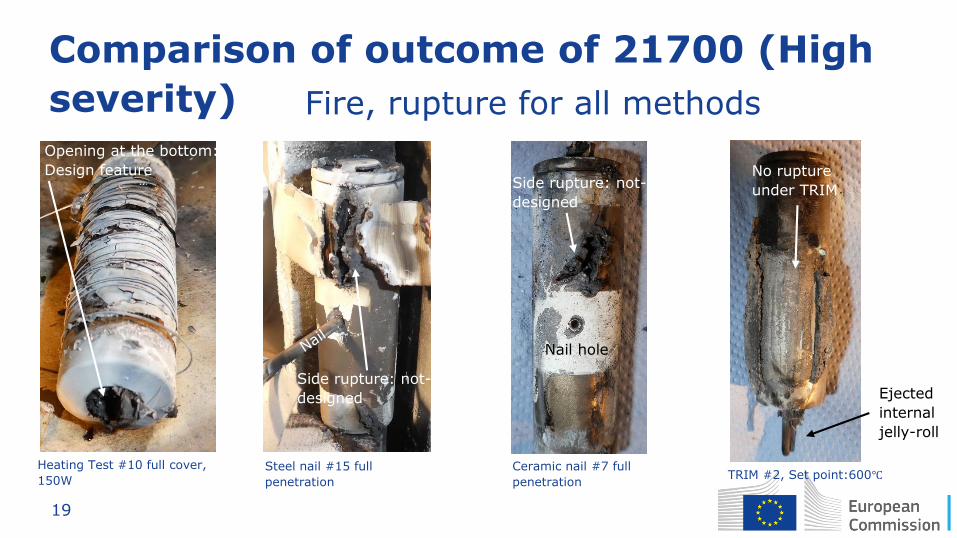
Comparison of outcome of 21700 (High
severity)
Heating Test #10 full cover,
150W Steel nail #15 full
penetration
Ceramic nail #7 full
penetration TRIM #2, Set point:600℃
Fire, rupture for all methods
Opening at the bottom:
Design feature
Side rupture: not-
designed
Side rupture: not-
designed
Nail hole
No rupture
under TRIM
Ejected
internal
jelly-roll

20
Comparison of outcome of pouch cells 2-plate heating Steel nail Ceramic nail TRIM, SP:600℃
39 A
h
Test#41
Test#43
Test#37
Test#34
40 A
h
Test#54
Test#59
Test#49
Test#46

21
Comparison of 96 Ah
2-plate heating test, 4.7 kW,
#24
Ceramic nail, #23, full penetration
Steel nail, #28, full penetration
TRIM, SP:600℃, #19
Side of the case
melted almost for
all heating tests
No major visual difference
between steal, ceramic nail
and TRIM

22
Global characterization – Mass loss
• Mass loss can be the sign
of the severity of TR
• A more determinant factor
is the cell type
• Initiation method used has
no significant influence on
severity
Factors Prob > F
Cell type <.0001
High-low resistance 0.0663
Method 0.0142
Cell type*High-low resistance 0.1802
Cell type*Method 0.3002
High-low resistance*Method 0.1742

23
Max surface temperature
Method type does not show
significant influence on surface
temperature
TR happened
No TR

24
Pass / Fail : Fire
No significant difference between methods
21
70
0
96
Ah
pris
mati
c
39
Ah
pou
ch
40
Ah
pou
ch
red:
fire
grey:
no
fire

25
Heating tests Energy input does not
influence significantly the
heating time to TR and
the max temperature.
The cooling may be
influenced by the bigger
heat mass of the 2-plate
heater.
0 500 1000 1500 2000
0
100
200
300
400
Temperature 2 plates
Energy 2 plates
Temperature 1 plate
Energy 1 plate
Tem
pera
ture
, E
nerg
y / o
C, W
h
Time / s
0
2
4
6
8
10
Vo
lta
ge
/ V
Cell voltage 2 plates
Cell voltage 1 plate
39Ah pouch Tests #10 (2 plates) and 11 (1 plate)

26
Nail Penetration
• No significant difference found
between ceramic and steel nail
• Stopping of nail significantly
influenced TR
• Cell type has significant
influence on TR
• Even though TR happened
when the nail was stopped, it
was delayed by several
minutes
• Discharge before TR was minor
(voltage drop is <50 mV)
100 150 200 250 1800 1820 1840
0
200
400
600
800
1000
Voltage drop
Temperature rear
Tem
pera
ture
, V
oltage d
rop / o
C, m
V
time / s
4
5
6
Displacement
Nail
dis
pla
cem
ent / m
m

27
TRIM Method Effect of Set point
• TR was triggered
successfully on all cell
types
• The energy input has no
significant influence on TR
• The set temperature has
minor influence on TR
• TR upon TRIM lead to
opening of safety device
• 1 out of 16 test, TRIM did
not heat up (reason not
clear)
45 60 75
0
1
2
3
4
Energy TP 300oC
Voltage TP 300oC
Energy TP 600oC
Voltage TP 600oC
Trigger
energ
y, C
ell
Voltage / W
h, V
time / s
0
300
600
Heating element 300oC
Surface (+) 300oC
Heating element 600oC
Surface (+) 600oC
Tem
pera
ture
/ o
C

28
Comparison of Dynamics
Video
0 2 4 6 8 10
-50
0
50
100
150
1000
2000
3000
4000
White smoke
Vo
lta
ge
dro
p / m
V
time / min
Voltage drop
Nail stopped
Smoke from
nailhole
Opening of CID
and vent
Intensive
venting
0
200
400
600
800
Te
mp
era
ture
/ o
C
Terminal (-)
Terminal (+)
Side (-)
Side (+)
Nail hole
Opposite side
Heating method Ceramic nail penetration
ISC
development TR
Damage
separator Heater becomes a
heat sink!
0 2 4 6 8 10
-50
0
50
100
150
1000
2000
3000
4000
Vo
lta
ge
dro
p / m
V
time / min
Voltage Drop
0
200
400
600
800
Te
mp
era
ture
/ o
C
Intensive venting ended
Venting started
Terminal (-)
Terminal (+)
Between cell&plate
Heating plate (1)
Side (-)
Side (+)
Heating plate (2)
Heating stopped
Despite similar final outcome (e.g. maximum
temperature and venting), the development of the
chain of failure is different!

29
Outline
• JRC experimental TP activity
• Initiation tests: Experimental description and results
• Assessment of initiation tests
• Next step: Short stack tests

30
Evaluation of initiation method
Still on-going

31
Evaluation of methods: if the purpose of
the method is to develop TR Initiation method
Indicators
Cell type Influence of parameters
Energy insert
Locality Readiness Manipulation Score
Heating Low High No Yes High 2
Nail High Low Yes Yes High 3
Ceramic nail High Low Yes Yes High 3
TRIM method Low Low Yes Yes Low 5
Inductive heating
Low Low Yes No TBC 3

32
Summary, findings
• All methods are able to trigger TR, no significant difference
was found between their effects
• The triggering energy has no significant influence on TR (it
may have an influence at pack level)
• All investigated methods seem applicable on pack level (with
limitation of initiation cell location for nail penetration)
• Nail penetration: • TR can be significantly influenced by parameters such as stopping the nail
• No difference between ceramic and steel nail
• TRIM method is easy to use and stable
• The chain of failure of local heating can be different than
global heating and can be considered closer to a realistic ISC

33
Ideal initiation method
Goal: Imitate realistic internal short circuit and simulate the
dynamics of internal and external failures
Properties:
• No significant discharge before trigger (i.e >95% SOC)
• Damaging the separator locally
• No major damage to the cell case
• Controllable and minimal energy input to avoid overheating
of adjacent cells and unwanted side reactions
• Minimal manipulation at pack level (manipulation is needed,
though)

34
Draft short stack test matrix
Initiation method
Automotive 39 Ah? pouch cells/stacks/modules
Test type Cell initiation Short stack Module Total
Heating?
Ceramic nail
TRIM method
Total 5 16 2 23
?

35
Further steps
• Improve understanding of the different failure mechanism
caused by different methods (e.g. local and global effects)
• Further complementary experimental work at material
level (e.g. thermal analysis) and cell level
• Procurement of stack-level TP testing almost complete
(contract signature expected June 2019)
• Further collaboration with Canada on TRIM method on short
stack and module initiation (together with other methods)
• Regular discussions with other parties are appreciated

36
Natalia Lebedeva, Franco Di Persio, Georgios Karaiskakis,
Ricardo Da Costa Barata, Theodora Kosmidou, Denis Dams,
Andreas Pfrang, Algirdas Kersys, Lois Brett
June 2019
Electrolyte leakage/venting verification
The European Commission’s
science and knowledge service
Joint Research Centre

37
Electrolyte leakage/venting verification - Current state of the art "…visual inspection without disassembling any part of the Tested-
Device" is adopted in Phase 1 as a method for verification of the occurrence of
electrolyte leakage and venting.
JRC concerns:
• Due to high volatility of some electrolyte components and limited release volume, electrolyte leakage and venting may not always be easily detectable, while potentially creating hazardous environment.
• Special measures may be required to ensure safety of inspecting personnel.
• Release of other substances, e.g. coolant, is currently treated equally to release of electrolyte.
• JRC work will focus on the development of more robust method(s) to first verify the occurrence of the electrolyte release and/or venting and, if possible, to quantify such release.

38
Free liquid electrolyte - amount
JRC has finalised research to quantify the amount of free liquid electrolyte in Li-ion battery (LIB) cells
3.6 ± 0.8 g (< 5 ml)
none
31.7 ± 8.5 g (ca. 30 ml)
35.8 ± 7.8 g (ca. 35 ml)
18.4 ± 0.6 g (15 to 20 ml)
none
N. P. Lebedeva, F. Di Persio, T. Kosmidou, D. Dams, A. Pfrang, A. Kersys, L. Boon-Brett, Amount of Free Liquid Electrolyte in Commercial Large Format Prismatic Li-Ion Battery Cells, Journal of the Electrochemical Society 166 (2019) A779-A786.

39
Free liquid electrolyte - amount
3.6 ± 0.8 g (< 5 ml)
none
18.4 ± 0.6 g (15 to 20 ml)
none
EU sales: 100.000 among top-10 most sold PHEVs in the EU
EU sales: 28.000 among top-10 most sold BEVs in the EU
World sales: 30.000
EU sales: 80.000 among top-10 most sold BEVs in the EU
N. P. Lebedeva, F. Di Persio, T. Kosmidou, D. Dams, A. Pfrang, A. Kersys, L. Boon-Brett, Amount of Free Liquid Electrolyte in Commercial Large Format Prismatic Li-Ion Battery Cells, Journal of the Electrochemical Society 166 (2019) A779-A786.

40
Free liquid electrolyte - composition
• Investigated cells contained the following compounds in their electrolytes*:
- Ethylene carbonate (EC)
- Dimethyl carbonate (DMC)
- Diethyl carbonate (DEC)
- Ethyl methyl (EMC)
- Ethyl acetate (EA)
- LiPF6
10001500200025003000
0.0
0.5
1.0
1.5
2.0
2.5
3.0
3.5
Type 3
Type 6 (x 20)
IR A
bsor
ptio
n
Wavenumber, cm-1
n (C=O)
d (-CH2-, -CH3)
n (C-H)
n (O-C-O)
* Based on information contained in MSDS and/or information sheets provided with the cells and JRC FTIR analysis of retrieved electrolytes For (experimental) details please see: N. P. Lebedeva, F. Di Persio, T. Kosmidou, D. Dams, A. Pfrang, A. Kersys, L. Boon-Brett, Amount of Free Liquid Electrolyte in Commercial Large Format Prismatic Li-Ion Battery Cells, Journal of the Electrochemical Society 166 (2019) A779-A786.

41
Free liquid electrolyte -toxicity
Solvent Volume of evaporated solvent*, ml
PAC-2 level PAC-3 level
Diethyl carbonate (DEC), CAS # 105-58-8
1.4 21.5
Dimethyl carbonate (DMC), CAS # 616-38-6
25 149
Acetonitrile (AN), CAS # 75-05-8
42 86
* Volume, solvent evaporates into, is defined as vehicle + 1-m clearance; 61.5 m3 in this study
N.P. Lebedeva, L. Boon-Brett, Considerations on the Chemical Toxicity of Contemporary Li-Ion Battery Electrolytes and Their Components, Journal of the Electrochemical Society 163 (2016) A821
PAC stands for Protective Action Criteria PAC-2: Irreversible or other serious health effects that could impair the ability to take protective action PAC-3: Life-threatening health effects
Can be achieved from
1 cell only

42
Free liquid electrolyte - conclusions
• Li-ion battery cells can contain free liquid electrolyte in amounts sufficient for the formation of potentially toxic atmosphere in enclosed spaces after a release of electrolyte from a single battery cell.
• It is especially alarming that Li-ion cells containing appreciable amount of free liquid electrolyte are used in mass-production PHEVs and BEVs, which are on the EU market since 2013 and 2010, and which belong to the top-10 most sold electric vehicle models in the EU.
• Release of the contained free liquid electrolyte represents the best case scenario as its amount corresponds to the minimum amount of electrolyte that can be released from a battery cell when the integrity of the cell casing is compromised.

43
time
1 Solid(-liquid) electrolyte residue
2 Vapours from released liquid electrolyte
3 Vented gases
Work in progress
1 Detection of Li-ion presence 2 3 + Gas detection
Possible approaches for detection of electrolyte release
1 Liquid electrolyte release
2 Vapours from released liquid electrolyte
3 Vented gases

44
Acknowledgement • BATTEST group
Akos Kriston (now JRC Ispra)
Franco Di Persio
Natalia Lebedeva
Vanesa Ruiz Andreas Pfrang
Denis Dams
Ibtissam Adanouj Lois Brett
Marek Bielewski
Emilio Napolitano
Ricardo Da Costa Barata
Special Thanks to:
• Harry Döring (ZSW)
• Michael Wörz (ZSW)
• Sebastian Trischler (ZSW)
• Dean MacNeil (NRC)
• Steven Recoskie (NRC)

45
•EU Science Hub: ec.europa.eu/jrc
•Twitter: @EU_ScienceHub
•Facebook: EU Science Hub - Joint Research Centre
•LinkedIn: Joint Research Centre
•YouTube: EU Science Hub
Stay in touch